Abstract
A key direction of the development of modern power systems is the application of a continuously increasing number of grid-forming power converters to provide various system services. One of the possible strategies for the implementation of grid-forming control is a control algorithm based on a virtual synchronous generator (VSG). However, at present, the problem of VSG operation under abnormal conditions associated with an increase in output current remains unsolved. Existing current saturation algorithms (CSAs) lead to the degradation of grid-forming properties during overcurrent limiting or reduce the possible range of current output. In this regard, this paper proposes to use the structure of modified current-controlled VSG (CC-VSG) instead of traditional voltage-controlled VSG. A current vector amplitude limiter is used to limit the output current in the CC-VSG structure. At the same time, the angle of the current reference vector continues to be regulated based on the emerging operating conditions due to the voltage feedback in the used VSG equations. The presented simulation results have shown that it was possible to achieve a wide operating range for the current phase from 0° to 180° in comparison with a traditional VSG algorithm. At the same time, the properties of the grid-forming inverter, such as power synchronization without phase-locked loop controller, voltage, and frequency control, are preserved. In addition, in order to avoid saturation of the voltage controller, it is proposed to use a simple algorithm of blocking and switching the reference signal from the setpoint to the current voltage level. Due to this structure, it was possible to prevent saturation of integrators in the control loops and to provide a guaranteed exit from the limiting mode. The results of adding this structure showed a five-second reduction in the overvoltage that occurs when it is absent. A comparison with conditional integration also showed that it prevented lock-up in the limiting mode. The results of experimental verification of the developed prototype of the inverter with CC-VSG control and CSA are also given, including a comparison with the serial model of the hybrid inverter. The results obtained showed that the developed algorithm excludes both the dead time and the load current loss when the external grid is disconnected. In addition, there is no tripping during overload, unlike a hybrid inverter.
Keywords:
virtual synchronous generator; grid-forming (GFM) inverter; current limiting; power converter; overcurrent; transient stability MSC:
93C10
1. Introduction
At present, the introduction and application of various generating units based on power converters continues in the power systems of various countries. Most of them operate as the grid-following current source, which follows the grid voltage measured by the phase-locked loop (PLL) controller [1,2,3]. As a result of the increasing number and capacity of such grid-following inverters, as well as the reduction in fossil-fuel-powered generation sources, the probability of various failures is increasing. This is because historically power systems have been designed based on the properties and capabilities of traditional synchronous generators [4]. This transformation has led to increased interest in the industry community in the new technology of grid-forming control for power converters [5]. Such control provides the opportunity for power converters to contribute system services in order to improve the reliability and stability of the power systems. In recent years, leading energy companies and international consortiums have been considering the grid-forming inverters as an effective means for safe and sustainable development of modern power systems [6,7,8]. One of the promising technologies for implementing the grid-forming control is an algorithm based on a virtual synchronous generator (VSG) [9]. However, in order to effectively apply the VSG concept, a number of fundamental problems need to be solved [10]. One of them is related to the operation of VSGs in abnormal conditions. Physically, this problem is caused by limitations of the maximum current through the power semiconductor switches. The increase in the power converter capacity and thermostatic accuracy allow it to withstand a higher current ratio but sufficiently increase the cost of the device. Consequently, as a rule, the power converters are designed for maximum allowable currents slightly exceeding their nominal values.
The technology of power converter protection against overcurrent is usually implemented as software with the help of the current saturation algorithm (CSA) as part of the VSG control. In case of disturbances in the grid (short circuits, overloads, voltage and frequency changes, etc.), the power converter switches to the current-limiting mode, and the main control loops of the VSG algorithm are blocked. This fundamentally changes the dynamics of the power converter operation and affects the processes in the power grid. In particular, the functions of formation of reference voltage for the grid, synchronization, etc., are blocked, which is unacceptable for the grid-forming inverters. At the same time, the number and importance of system services performed by the grid-forming inverters increase, for the power system stability. In this regard, it is necessary to take into account their ensuring in the current-limiting mode; however, at the same time, it is also necessary to maintain the response speed and accuracy of the CSA for the protection of the power converter itself. Observance of this trade-off is a difficult task, which is illustrated in Figure 1 [11].
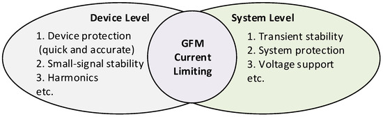
Figure 1.
Schematic interpretation of the CSA impact on various processes in power converters and power systems.
There are various strategies for limiting the output current of the VSG-based power converters. In general, they can be divided into two major groups: direct and indirect methods [12]. Direct methods limit the output current by generating appropriate reference signals for the inner current control loop [13] or, less frequently, for the pulse-width modulation [14,15]. For this purpose, instantaneous current values [16,17], only its amplitude [18,19], or its vector [20] are used. Among these three methods, instantaneous value limitation is the simplest and fastest way to protect power switches. However, due to the ‘clipping’ of the upper part of the reference signal, the output currents are no longer sinusoidal [19]. Amplitude limitation allows ensuring sinusoidal output current; however, the phase of the current (the angle between the current vector and the d-axis) remains undefined, which requires additional measures to ensure VSG stable operation [21]. In this regard, simultaneous limitation of amplitude and setting of a specific phase of current is effective, but the latter depends on the parameters of the grid and outer control loops of the VSG. As a result, the current phase is usually set to zero [22,23]. On the contrary, in [24] it is shown that a large value of the angle is necessary to maintain stability. As a result, a trade-off is required to set the current phase, which, given its multifactor dependence, becomes a non-trivial task and requires complex approaches [25,26]. There are also solutions to use a PLL controller for the current phase generation [20,27], but this leads to well-known problems of the power converter operation in weak grids [28,29]. In general, the approaches are summarized by setting a specific value for the current phase, which allows ensuring strict control of the output current. However, because of this, the properties of the grid-forming inverter are almost completely lost, which fundamentally raises the question of the applicability of such a CSA [11]. Direct methods also include approaches to limit power reference values in outer control loops [12]. However, these controllers are relatively slow—their response speed can be up to ten periods of the industrial frequency.
The indirect methods include limiting the use of virtual impedance [30,31] and voltage reference for the outer controllers [32]. The use of virtual impedance is an extremely effective method, and the properties of the grid-forming inverter are preserved, unlike current signal limiters. But on the other hand, the virtual impedance values are selected for the most severe possible disturbance, which results in limiting the usable range of the output current [33]. In this regard, the efficiency of the system services provided by the grid-forming inverter is significantly reduced.
As a result, both direct and indirect methods have their pros and cons. Therefore, in recent years, hybrid methods combining the benefits of different methods have been proposed [34,35]. A combination of using virtual impedance to control the phase of the output current and a current reference amplitude limiter seems to be quite effective [33,35]. This allows us to extend the range of the output current in the limiting mode. However, in this case the process dynamics in the limiting mode become fully dependent on the ratio of virtual impedance Rv/Xv. Its setting remains an outstanding challenge, given the need for a trade-off between impedance values to ensure the VSG stability. In addition, all CSAs are characterized by two main problems. First is the integrator saturation in outer control loops, and second is the lock-up problem (or ‘freezing’) in the current-limiting mode. Both of them prevent a return to the normal operation [16,36]. The problem of integrator saturation is solved using known methods, e.g., conditional integration [37,38]. At the same time, the return to normal operation is a much more complicated task. The implementation of the solution depends on the used structure of the VSG algorithm, the CSA, and on the value of voltage nadir or zenith in the grid. Furthermore, it is often very difficult to fulfill this for the small disturbances. Table 1 summarizes the results of a comparison of the main properties of existing current-limiting methods. Thus, the direct limiting methods are fast, while the indirect methods preserve the properties of the grid-forming source; however, the effective hybrid approaches that combine these advantages and have efficient and robust algorithms for exiting the limiting mode under any type of disturbance have not yet been proposed.

Table 1.
Features of direct, indirect, and hybrid methods.
The contribution of the paper is as follows:
- A novel structure of the current-controlled VSG (CC-VSG) with feedforward control has been proposed, which is a current source with virtual impedance. In this case, the reference signal for the inner current control loop is formed taking into account the dynamics of the virtual synchronous machine, which has no current limiting. Due to the presence of the inner current control loop in the CC-VSG, only the amplitude of the reference current vector is directly limited. The phase of the output current remains regulated due to the continuous formation of virtual currents based on the known equations of the synchronous machine. Thus, the properties of the grid-forming source (power synchronization without the PLL, voltage, and frequency control) are preserved.
- To avoid saturation of the voltage controller, a blocking algorithm is proposed, which is activated by a signal from the current limiter. The resetting of the blocking signal and exit from the limiting mode occur naturally due to continuous regulation of the output current phase (demonstrated by saving the voltage feedback). In this way, an extremely simple and reliable way to prevent saturation and lock-up of the control system in the current-limiting mode is implemented.
The rest of the paper is organized as follows. Section 2 discusses the considered system of nonlinear equations with a traditional voltage-controlled VSG algorithm and a modified CC-VSG algorithm. The analysis of power-angle curves for normal operation and current-limiting mode is also performed. Section 3 presents the results of time-domain simulation of the test system with VSG-based inverters under different disturbances. Section 4 verifies the properties of the proposed CC-VSG with CSA using the developed prototype of the inverter, as well as presents its comparison with existing solutions. Section 5 concludes the paper.
2. Challenges of VSG Current Limiting
2.1. Traditional VC-VSG with Current Reference Saturation and Fixed Angle
Figure 2 shows the overall structure of the grid-connected power converter with an output LC filter with parameters Lf and Cf. An ideal DC voltage source Udc is used as the primary source. The controlled parameters of the VSG are icv is the output current of the inverter, and uo and io, the voltage and current at the point of common coupling (PCC) behind an LC filter. The pulse width modulation (PWM) is used to control the power switches, for which uabc,m is the reference voltage signal. The power grid is represented as an ideal AC voltage source with the following parameters: ug and ωg are the grid voltage and frequency, and Lg and Rg are the equivalent inductance and resistance from the PCC to the grid.
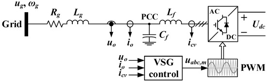
Figure 2.
Structural diagram of the studied network with a grid-forming inverter.
For the analysis of the processes emerging during current-limiting mode within the VSG algorithm, a generic large-signal model corresponding to the diagram in Figure 2 is formed. A traditional voltage-controlled VSG (VC-VSG) algorithm consists of outer and inner control loops operating in the dq reference frame (Figure 3) [39]. The outer ones include the active power controller (APC) and the AC voltage controller (VC). The first one is based on the known swing equation and forms the internal angle θVSG to perform Park transformations. The voltage controller forms the reference signal EVSG for the inner cascaded voltage and current controllers (CVC and CCC). The CVC and CCC are the basis for the VC-VSG structure. The CCC is the output part of the whole control system and forms the voltage reference signals udq,m for PWM. The direct CSA described earlier can be realized between the inner control loops. Figure 3 shows a generalized representation of the control scheme without detailed reflection of the control loops, which can be found in [10].
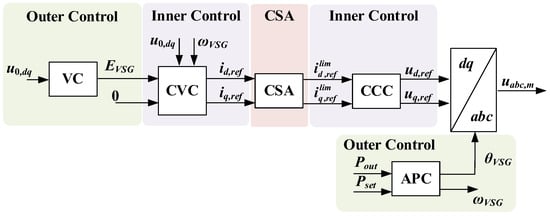
Figure 3.
Structural diagram of a traditional VC-VSG with the addition of CSA.
Typically, the dynamics of the outer active power control loop are more than ten times slower than the dynamics of the inner control loops [40]. Therefore, for analyzing the processes in the current-limiting mode, the inner control loops can be neglected due to their much faster response [41]. On this basis, the VC-VSG can be represented as a voltage source (Figure 4a), whose output active power Pout in the normal operation (without current limiting) is described by the well-known Equation (1) under the assumption of zero active resistance of the grid [42]:
where Ug is the root mean square (RMS) grid voltage in pu, δ is the angle between the phases of VSG and grid voltages, Lg is the equivalent inductance of the grid in pu, which includes Lf, and Imax is the maximum allowable current reference for the CSA.
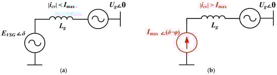
Figure 4.
Equivalent circuit of the traditional VC-VSG structure: (a) during normal operation, (b) in current-limiting mode.
Under various disturbances, the output current icv may exceed the maximum allowable value Imax. In this case, the VSG switches to the current-limiting mode with the set amplitude Imax. The internal EMF vector EVSG is no longer regulated, and the voltage at the PCC is formed depending on the operating conditions. In this case, the output power of the inverter is limited by the current Imax and varies similarly to the grid voltage. In this case, the equation for power calculation has the form (2) and is characteristic of the current source, which can represent a traditional VC-VSG in the current-limiting mode (Figure 4b) [43]:
where is the maximum active power in the current-limiting mode.
Based on Equations (1) and (2), a nonlinear model can be formed that describes the behavior of the traditional VC-VSG during normal operation and in current-limiting mode (Figure 5). It can be seen that the current phase φ is a freely set value and is not included in the continuous control loop.
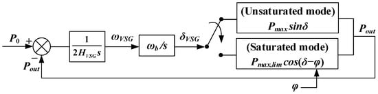
Figure 5.
Structural diagram of APC for a traditional VC-VSG.
With the help of the obtained nonlinear model, the power-angle P-δ curves for different operating modes of the VC-VSG were plotted. The unsaturated power-angle P-δ curves are based on Equation (1). The saturated power-angle P-δ curves are based on Equation (2). Figure 6 shows the power-angle curves corresponding to normal operation and current-limiting mode due to overload occurrence with different values of the angle φ = (0°, 45°, 90°) [44]. In normal operation, the VC-VSG operates at the equilibrium operating point A on the curve that corresponds to the voltage source (Figure 6a). When a disturbance leading to a current-limiting mode occurs, e.g., as a result of a voltage sag in the grid, the operating point is moved to point B. Next, under the accelerating power P0, the operating point moves to point C, where a transition to the P-δ curve for the current-limiting mode occurs. At the same time, the accelerating power P0 is still greater than the decelerating power Pout, which leads to a further increase in the angle towards point D, causing instability of the VC-VSG. The situation is improved by shifting the P-δ curve in the current-limiting mode by the angle φ = 45° (Figure 6b). In this case, the power balance and the inverter stability at point C are achieved. When the grid voltage is restored, there is a transition to point D on the shifted curve. At this point, the decelerating power Pout exceeds P0, which contributes to the reduction in the angle δ and the movement of the operating point to point E. Then, the inverter exits the current-limiting mode at point A. Thus, the shift in the P-δ curve in the current-limiting mode contributes to the stability improvement. However, the situation changes if the shift is even greater with φ = 90° (Figure 6c). When the grid voltage is restored, the operating point under the decelerating power Pout will move from point C to D and then to E, at which the power balance will be achieved. As a result, there will be a VC-VSG algorithm lock-up in the current-limiting mode under normal operating conditions.
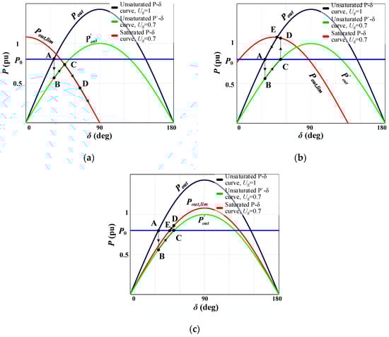
Figure 6.
Power-angle curves reflecting the mechanisms of the traditional VC-VSG operation in the current-limiting mode at different phases of the output current: (a) φ = 0°, (b) φ = 45°, (c) φ = 90°.
Thus, from the three cases considered, it follows that the stable operation in the current-limiting mode and return to normal operation depend on the angle φ. The value of this angle determines the position of the curve Pout,lim(δ + φ). The boundary conditions for the angle φlim are defined by Equation (3). To prevent instability in the current-limiting mode, the descending part of the Pout,lim(δ + φ) curve must be to the right of the P′out(δ) curve at the point of intersection with P0. This condition corresponds to the left side of Equation (3). To return to normal operation and prevent lock-up in the current-limiting mode, the ascending part of the Pout,lim(δ + φ) curve must be to the left of the Pout(δ) curve at the point of intersection with P0. This condition corresponds to the right side of Equation (3). For the considered case, according to Equation (3), the boundary values of the angle φ will be as follows: 9.8° < φlim < 77.4°.
Based on the presented theoretical analysis, it follows that the selection of a specific angle for the output current phase φ is a difficult task. However, this is necessary to ensure inverter stability in the current-limiting mode and successful return to the normal operation. This is due to the dependence on the operating conditions of the external grid. Therefore, the most effective way is to continuously adjust the current phase φ to shift the power-angle curve depending on the emerging operating conditions.
2.2. Proposed CC-VSG with Current Saturation Algorithm
As a result, it is necessary to ensure the inverter’s stability in the current-limiting mode under various disturbances and the reliable transition to the normal operation. Therefore, this paper proposes to modify the previously developed structure of CC-VSG with angular frequency deviation feedforward control [45]. The concept of CC-VSG is based on the use of virtual impedance Zv to form the reference current icv,ref as the difference between the internal EMF EVSG and the voltage U0 at the PCC according to Equation (4):
Based on Equation (4), the equivalent circuit of the CC-VSG has the form of a current source connected to the grid through a virtual impedance (Figure 7) [46]. This algorithm was described in detail earlier in [47], where it was also compared with various analogs. However, the behavior of its operation in the current-limiting mode has not been considered so far.
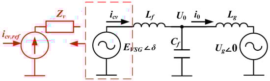
Figure 7.
Equivalent circuit of the developed CC-VSG.
The structural diagram of the modified CC-VSG, including the CSA, is shown in Figure 8a. The main feature of this structure is the way of forming reference values for the inner current control loop. For this purpose, two parallel control loops are used. The first of them is responsible for the formation of active and reactive power reference values (Pset and Qset). The second loop reproduces the dynamics of the virtual synchronous machine and forms the virtual output powers PVSG and QVSG (Figure 8b), which are then added to the reference values. From the resulting reference power values Pref and Qref, the reference current values icvdq,ref are calculated, which are already provided to the CSA. A fast and efficient direct method of limiting the amplitude of the reference current vector [48,49] is used for the CSA. The basis of the CSA used is Equation (5):
where , .
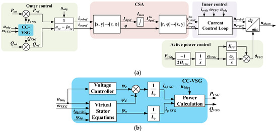
Figure 8.
Structural diagrams of the (a) proposed CC-VSG, including the CSA, and (b) control loops reproducing the dynamics of the virtual synchronous machine.
Due to such separation, the currents of the virtual synchronous machine continue to change continuously due to the PCC voltage feedback, including in the current-limiting mode. This ensures the formation of the required current phase φ. It should also be noted that the proposed structure of CC-VSG does not need a PLL controller. The synchronization in the current-limiting mode continues to be carried out using the swing equation, which operates with zero active power reference. This guarantees the stable operation of the CC-VSG.
Similarly to the previous Section 2.1, the APC for the proposed CC-VSG structure is further considered (Figure 9). A number of assumptions are made including the following: (i) the active resistances are excluded, (ii) the steady-state operation is considered, (iii) the inner current control loop is excluded, and (iv) the current from the filter capacitor is neglected, which allows us to consider i0 = icv. The exclusion of active resistance and capacitive reactance definitely leads to some errors. However, taking them into account significantly complicates the analytical dependencies, which contradicts the purpose of this study. The main aim of this study is to provide a qualitative analysis of the processes occurring. In particular, excluding the filter capacitive reactance in the P-δ analysis presented below leads to an error of about 6%. It is also assumed that the q-axis leads the d-axis by 90°, and phase A current coincides with the q-axis; then uod = U0sinδVSG and uoq = U0cosδVSG. In Figure 9, the transfer function G(s)P/δ describes the APC and is formed based on its structural diagram shown in Figure 8a.
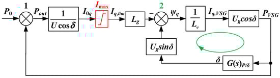
Figure 9.
Structural diagram of the APC for the CC-VSG.
Based on the instantaneous power theory [50], taking into account the assumed conditions during normal operation, the CC-VSG power output is described by Equation (6):
In order to find the output current, Equation (4) is used, and the voltages from the well-known grid equations in the rotating reference frame [51] are substituted into it. As a result, the equation for the output power takes the following form (7):
The power-angle curve for the normal operation corresponding to Equation (7) is shown in Figure 10 (red curve). This curve is shifted along the horizontal axis by the value (P0 · Lv)/(Lg + Lv). It can also be seen that the obtained curve differs from the curve for a classical current source shown earlier and is very similar to the curve for a voltage source.
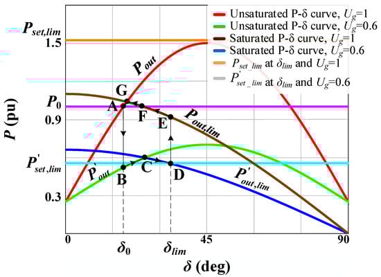
Figure 10.
Power-angle curves reflecting the mechanisms of the proposed CC-VSG operation in the current-limiting mode.
The current-limiting mode in the structural diagram is taken into account by the limiter shown in Figure 9 (highlighted in red). For this mode, considering the given structure, it is possible to find the output current I0q (8), which is formed before the limiter:
Substituting Equation (8) into the equation of output power after the limiter, Equation (9) is obtained:
Thus, for the proposed CC-VSG structure, a simple power-angle curve in the current-limiting mode is obtained (brown curve in Figure 10), which is identical to the curve of a current source given earlier.
The fundamental difference lies in the formation of the angle δ. As follows from the structural diagram (Figure 9), there are two negative feedbacks: (i) for adder ‘1’ by power and (ii) for adder ‘2’ by voltage. In the current-limiting mode, the feedback for adder ‘1’ is no longer operating, in the same way as for the traditional VC-VSG structure. However, unlike the latter, the angle δ continues to be controlled by the second feedback (highlighted in green) until zero is formed at adder ‘2’. Physically, this corresponds to the achievement of both PVSG = 0 and the power balance. On this basis, Equation (10) can be formed, which reflects the steady-state value of the angle δlim in the current-limiting mode.
As follows from Equation (10), the angle value in the limiting mode depends on the current limiter reference and the grid impedance. The voltage signal provides continuous regulation and the necessary δlim value to ensure stable operation of the CC-VSG in the current-limiting mode. Therefore, in the current-limiting mode, the inverter stability will be maintained when Lg∙Imax < Ug. The operating range for the developed algorithm depends on both the voltage sag Ug and the specified value of Imax. Figure 10 shows the case with Ug = 0.6 pu, Imax = 1.1 pu, and Lg = 0.3 pu. Consequently, the permissible grid impedance is Lg = 0.545 pu, which can be accepted as the operating range limit in this case. A grid with such impedance is classified as a weak grid, and, therefore, the developed algorithm is suitable for use in such grids. However, in practice, a voltage sag up to Ug = 0.8 pu should be considered more realistic during the overload case. Under more severe voltage sags, the low voltage ride-through (LVRT) logic begins to operate. Taking into account the assumed value of Ug for the limiting mode, the grid impedance is 0.727 pu. The modification of the proposed algorithm for its application in ultra-weak grids with Lg = 1 pu is a future work.
When a similar disturbance occurs (Section 2.1), the operating point moves from the normal state A to B, which is located on the P-δ curve, corresponding to the reduced grid voltage (green curve in Figure 10). Then there is a movement to point C under the accelerating power P0 and a transition to the P-δ curve in the current-limiting mode (blue curve in Figure 10). As can be seen earlier for the traditional VC-VSG, the movement to point D occurs under the accelerating power P0 with further inverter instability. However, for the developed CC-VSG structure, the movement to point D will occur until the moment of reaching a new power balance at a specific angle δlim, which is determined by Equation (10). At point D, the new value of the reference power is described by Equation (11) and depends not only on the grid parameters, but also on the controlled angle δlim:
Thus, in case of disturbances leading to the current-limiting mode and the blocking of the feedback on adder ‘1’, the feedback on adder ‘2’ will continue to operate until a new power balance is formed between and Pout,lim at angle δlim. When the grid voltage is restored, the operating point moves to point E, but the reference power also takes a new value, Pset,lim, which is significantly higher than the output power at this point. As a consequence, the operating point moves further to point F, and the value of Pset,lim decreases. But at point F, the power balance is not achieved. This causes further movement to point G and eliminates the lock-up in the current-limiting mode in comparison with a traditional VC-VSG algorithm for this point on the P-δ curve. The power balance is achieved at point G, where there is a crossing of two curves for normal operation and the current-limiting mode. This guarantees the transition to the normal P-δ curve with further movement to the initial point A under the decelerating power Pout.
It should be noted that achieving balance at point G due to the features of the developed CC-VSG structure may cause the algorithm lock-up in the current-limiting mode at this point. To prevent this phenomenon, the following is proposed. As for any structure of the direct CSA, it is necessary to block the VC to exclude the integrator saturation in its structure. The latter can cause either an overvoltage during the restoration or even the CC-VSG instability. Moreover, the existing various approaches provide a reliable solution to this challenge only in the grid-connected operating mode of the grid-forming inverter [16]. In the stand-alone mode, there is no external source with the help of which the grid voltage will be restored after removing the disturbance. This makes it difficult to identify the restoration of the normal operation and may cause the VSG algorithm lock-up in the current-limiting mode. Therefore, the VC structure shown in Figure 11 is proposed to provide a reliable transition from one curve to another at point G. The principle of the algorithm is to block the VC in the current-limiting mode by switching the reference signal Uset to the directly controlled signal U0. Moreover, a limiter with an upper limit equal to Uset is also used, which ensures the return to normal operation when the grid voltage is restored. In this structure, a comparison of the output current amplitude Icv with the reference Imax via the relay block is used as a control signal. The relay block has a hysteresis function. The relay is on when the input signal reaches the value Imax. On the contrary, the relay is off only when the input signal becomes less than 98% of the value Imax. The latter provides some noise immunity. When the relay is off, the switch is in position 1, and the voltage controller is in normal operation. When the relay is on, the switch moves to position 2, which enables VC blocking in the current-limiting mode. This structure is the only way to ensure a guaranteed exit from the limiting mode and subsequent continuous voltage regulation according to the reference value, regardless of the voltage restoration and the severity of the disturbance.
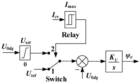
Figure 11.
Proposed VC structure with blocking algorithm in the current-limiting mode.
Therefore, the following conclusions can be drawn from Figure 8 and Figure 11. The current vector amplitude limiter used in the proposed CC-VSG structure can be easily applied to other typical grid-forming control methods (droop control, other VSG topologies, dispatchable virtual oscillator control, or matching control), which have an inner current control loop in their structure [11,52]. However, in other grid-forming control structures, in the case of transition to the current-limiting mode, it is infeasible to ensure the preservation of the properties of the grid-forming source without additional solutions. For the considered CC-VSG, the addition of only a current limiter does not lead to the loss of the grid-forming source properties. However, the issue of eliminating lock-up in the current-limiting mode under various CC-VSG operating conditions remains. The latter is solved by introducing a blocking algorithm for the AC voltage controller. The blocking algorithm proposed in this paper can also be successfully applied in other grid-forming control methods with an outer AC voltage control loop. This is possible since the excitation flux linkage ψe of the virtual excitation winding within the CC-VSG algorithm is similar to the formation of the voltage amplitude reference in other VSG topologies. A qualitative comparison of the developed method with other current limiting strategies is given in Table 2.
Table 2.
Performance comparison of different current-limiting control methods.
3. Comparative Analysis of Traditional VC-VSG and Proposed CC-VSG During Overcurrent Limiting
In this section, the results of time-domain simulation of the proposed CC-VSG structure with CSAs are presented in comparison with a traditional VC-VSG algorithm by using MATLAB/Simulink R2024b software. The developed structure was verified in case of current limiting due to various factors. In addition, the grid-connected operation and stand-alone operation with different load characteristics were considered. The latter is extremely important, as it allows us to demonstrate the preservation of the properties of the grid-forming inverter during the transition to the stand-alone mode. In this mode, the grid-forming inverter must continue to form the reference parameters for the grid under the CSA operation. Considering these circumstances, the power system model shown in Figure 12 was simulated. The main system parameters are given in Table A1 in Appendix A. During grid-connected operation, changes in the grid voltage and inverter active power reference were reproduced, which led to overcurrent and CSA operation. Switching to the stand-alone mode is performed via switch S. In stand-alone mode, the R-load provides the inverter’s active power load, and the RLC-load represents a different combination of loads [53], the change in which causes the CSA operation.
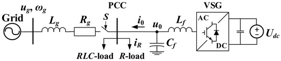
Figure 12.
Schematic diagram of the test scheme.
3.1. Simulation Test #1: A Voltage Sag During Grid-Connected Operation for the Traditional VC-VSG
For a traditional VC-VSG algorithm, the grid-connected operation with active power reference P0 = 0.6 pu was considered. As a disturbance, a voltage sag to Ug = 0.7 pu at time t1 = 2 s and subsequent recovery at t2 = 5 s was reproduced. Under this disturbance, the current limiter is operated with the reference value Imax = 0.9 pu. As can be seen from Figure 13, the process dynamics in the limiting mode and after the disturbance removal differ depending on the set angle for the output current phase φ.
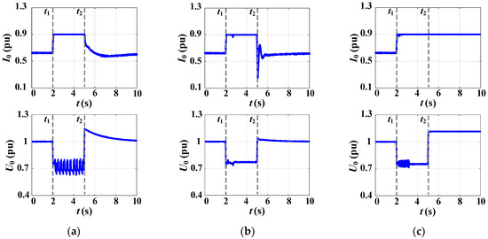
Figure 13.
Waveforms of RMS currents and voltages of the traditional VC-VSG in the case of grid voltage sag and different phases of output current: (a) φ = 0°, (b) φ = 45°, (c) φ = 90°.
When φ = 0°, instability in the current-limiting mode occurs, which is expressed in the form of undamped voltage oscillations (Figure 13a). This characteristic of the process is caused by the infeasibility of achieving the power balance in the existing operating conditions due to the selected angle φ. At the same time, the normal operation occurs after the voltage is restored. When the angle is increased up to φ = 45°, inverter stability in the current-limiting mode and a successful transition out of it are obtained (Figure 13b). Consequently, the specified value of the angle is suitable for ensuring stable operation of the VC-VSG under the considered disturbance and grid parameters. If the angle is increased up to φ = 90°, the stable operation in the current-limiting mode is also obtained. However, after voltage restoration, the VC-VSG continues to operate in the limiting mode with the maximum allowable current Imax, which leads to the overvoltage (Figure 13c). Such a value of the angle φ turns out to be excessive for the emerging operating condition. In summary, the obtained simulation results confirmed the theoretical conclusions made in Section 2.1 about the necessity of continuous control of the output current phase for the VC-VSG inverter.
3.2. Simulation Test #2: A Voltage Sag During Grid-Connected Operation for the Proposed CC-VSG with the CSA
A similar disturbance was reproduced using the proposed CC-VSG with the CSA (Figure 14). During modeling, there is also a voltage sag at the PCC at t1 = 2 s (Figure 14a). At the same time, the inverter output current increases and is limited by the reference value Imax = 0.9 pu (Figure 14b). As it was noted earlier, in the developed control structure in the current-limiting mode, the voltage feedback through the virtual stator equations is preserved. Due to this feature, even when the VC is blocked in the current-limiting mode, the current phase control continues. This is clearly seen by the change in the VSG currents idq,VSG (Figure 14c). Since the disturbance is caused by the grid voltage sag, there is an increase in the id,VSG component, which in the considered structure is responsible for regulating the output reactive power. Thus, as can be seen from Figure 14d, the reactive power increases and the active power decreases accordingly. At the same time, it is clearly seen that the virtual currents idq,VSG are not limited and exceed the maximum allowable current Imax. This demonstrates the process of parameter regulation even in the current-limiting mode. The return to normal operation at t2 = 5 s demonstrates a reliable transition from the limiting mode. Moreover, all waveforms do not contain oscillations, which confirms the CC-VSG stability in this case.
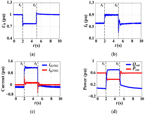
Figure 14.
Simulation results for the proposed CC-VSG with the CSA under grid voltage sag: (a) RMS voltage at the PCC, (b) RMS output inverter current, (c) VSG currents, and (d) output active and reactive power.
3.3. Simulation Test #3: A Change in the Active Power Reference During Grid-Connected Operation for the Proposed CC-VSG with the CSA
As the second disturbance for the developed CC-VSG structure, a change in the active power reference Pset from 0.6 pu to 1 pu is considered at t1 = 2 s. The resulting change in the inverter active power has a small effect on the grid voltage and frequency, as follows from Figure 15a. This is due to the presence of an equivalent of the external grid in the test scheme. At the same time, the inverter current changes to the maximum allowable current, Imax = 0.9 pu (Figure 15b). At the same time, due to insignificant changes in the controlled signals (grid voltage and frequency), the inner virtual currents idq,VSG formed by outer controllers also change insignificantly (Figure 15c). In addition, despite the change in the active power reference to Pset = 1 pu, the inverter output power does not exceed the value Pout = 0.9 pu. This confirms the effective operation of the proposed CSA. At t2 = 5 s there is a transition to the initial operation. Throughout the whole process, the stable operation of the CC-VSG is maintained without oscillations and significant deviation of the frequency ωVSG. Consequently, the results of test #3 prove that in the current-limiting mode, the synchronization continues without PLL using a swing equation that operates with zero active power reference.
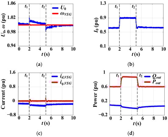
Figure 15.
Simulation results for the proposed CC-VSG with the CSA under active power reference change: (a) RMS voltage at the PCC and VSG frequency, (b) RMS output inverter current, (c) VSG currents, and (d) output active and reactive power.
It follows from the above results that regardless of the outer controller that caused the output current increase (APC corresponds to the q-axis component or VC corresponds to the d-axis component), the proposed CSA is effectively operated. At the same time, further reliable transition from the limiting mode without negative consequences is ensured. It is worth noting that during grid-connected operation, the proposed algorithm of the VC blocking in the current-limiting mode has no impact. In particular, when using the well-known conditional integration [54], the transient process has a similar character as with the developed blocking algorithm.
3.4. Simulation Test #4: A Step Change in Load During Stand-Alone Mode for the Proposed CC-VSG with the CSA
In the stand-alone mode, the step and gradual separate changes in parameters R, L, and C for the RLC-load are carried out as the disturbances. This allows us to evaluate the performance of the proposed CSA for the CC-VSG under various changes in the inverter output current. In all cases, there is always a constant R-load, as can be seen in Figure 12, which provides an initial current I0 ≈ 0.8 pu for the CC-VSG. At the same time, the CC-VSG tends to maintain the grid voltage and frequency close to the specified references. The latter leads to the operation of outer voltage and frequency controllers and, accordingly, to the increase in the inverter output current. Figure 16 shows a step change in RLC-load at t1 = 2 s with subsequent return to the initial value at t2 = 5 s. The waveforms in Figure 16 show that, irrespective of the nature of the load being varied (active, inductive, or capacitive), there is a decrease in the current phase and the grid voltage at the PCC. The change in the current phase clearly shows the change in the ratio between the active and reactive components of the inverter current. At the same time, the frequency changes gradually, returning to the initial value due to the secondary frequency control. In all three cases, the inverter output current is limited by the CSA reference, where Imax = 0.9 pu.
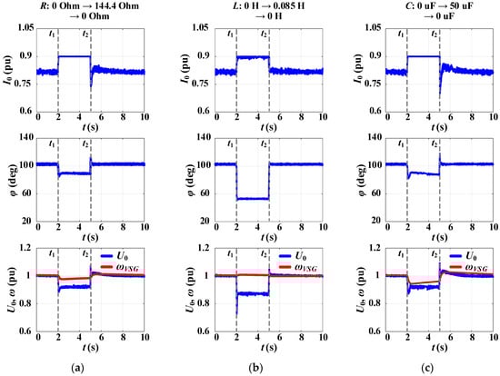
Figure 16.
Simulation results for the proposed CC-VSG with the CSA under step change in RLC-load: (a) R-load, (b) L-load, (c) C-load.
3.5. Simulation Test #5: A Gradual Change in Load During Stand-Alone Mode for the Proposed CC-VSG with the CSA
A gradual change in RLC-load (Figure 17) is performed by its connection at t1 = 2 s and subsequent change from t2 = 4 s to t3 = 6 s. From t4 = 8 s to t5 = 10 s, there is a return to the initial value of the load. From the obtained waveforms in Figure 17, it follows that there is a reliable operation and transition from the current-limiting mode. At the same time, the frequency control and voltage formation at the PCC continue without any oscillations.
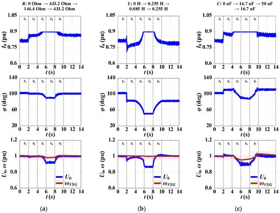
Figure 17.
Simulation results for the proposed CC-VSG with the CSA under gradual change in RLC-load: (a) R-load, (b) L-load, (c) C-load.
The results of tests #4 and #5 show that within a wide range of changes in the RLC-load, R = 0–433.2 Ohm, L = 0–0.255 H, and C = 0–50 μF, the required values of grid voltage and frequency are maintained. Consequently, the proposed CC-VSG algorithm in the current-limiting mode preserves the properties of the grid-forming inverter. At the same time, in the case of gradual load change, the continuing change in the current phase in the limiting mode in accordance with the emerging operating conditions is clearly seen. This confirms the maintenance of the grid parameters control due to the presence of the second voltage feedback (Figure 9).
3.6. Simulation Test #6: Different Approaches to VC Blocking Within CC-VSG Structure Under Gradual Change in C-Load and Stand-Alone Mode
Figure 18 shows the simulation results comparing different approaches to the VC blocking: (i) without blocking algorithm, (ii) conditional integration, and (iii) the proposed algorithm (Figure 11). As a disturbance, the C-load is connected at t1 = 2 s, followed by a gradual increase in capacitance from t2 = 4 s to t3 = 6 s. From t4 = 8 s to t5 = 10 s, there is a return to the initial capacitance. In this case, the absence of a VC blocking algorithm only leads to the transition to the current-limiting mode after the start of a gradual increase in C-load (red dashed line in Figure 18a). Due to the current limiting, the VC is unable to regulate the voltage level. Thus, a continuous error is formed at the integrator input (Figure 11), leading to its saturation. This causes an increase in the output value ψe throughout the entire load variation interval. At t = 9 s, the error sign changes and the value of ψe begins to decrease. However, due to the accumulated error value, it takes almost 5 s for ψe to decrease to its initial value, with obvious overvoltage. In addition, the time interval from t = 9 s to t = 14 s is characterized by an increased output current exceeding the reference value Imax. As a result, the CC-VSG exits the limiting mode only at t ≈ 14.7 s, which is highlighted by the green dashed line in Figure 18a.
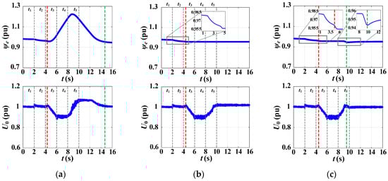
Figure 18.
Simulation results for the proposed CC-VSG with the CSA and different VC blocking algorithms: (a) without blocking algorithm, (b) conditional integration, and (c) proposed algorithm.
The addition of conditional integration solves the problem of integrator saturation (Figure 18b). The start of the process is similar to the previous case. However, the transition to the current-limiting mode and the VC blocking occur simultaneously, as highlighted by the red dashed line in Figure 18b. During load changes that occur up to t5 = 10 s, there is no change in ψe due to the VC blocking. However, the absence of voltage regulation when the C-load is decreased at t5 leads to an overvoltage. The latter leads again to the CC-VSG operating with an increased output current more than Imax. Thus, the control system is locked-up in the limiting mode without the ability to regulate the voltage.
When the proposed VC blocking algorithm is used, it also eliminates the integrator saturation (Figure 18c). The curves of ψe and U0 are similar to those presented in the previous experiment up to t = 9 s. The transition to the current-limiting mode and the VC blocking are highlighted by the red dashed line in Figure 18c. Despite the VC blocking, when the input voltage signal exceeds the Uset reference, an error is formed at the integrator input (Figure 11). This triggers the voltage controller and causes a change in the output value ψe (at t ≈ 9 s). The output current also returns to its normal value. The control system exits the current limiting and VC blocking modes, which is highlighted by the green dashed line in Figure 18c. Thus, the current limiting lock-up is excluded, and the correct operation of the developed CC-VSG algorithm in various operating conditions is ensured.
Based on the results of the analytical analysis and the time-domain simulation, a summary table was formed (Table 3). Table 3 reflects a qualitative and quantitative assessment of the proposed solution and the VSG structure widely used in the literature.
Table 3.
Comparative assessment of the traditional VC-VSG and proposed CC-VSG with the CSA.
4. Experimental Verification
To confirm the effectiveness of the developed CSA as a part of the CC-VSG, its verification was also performed using the developed experimental prototype of a three-phase inverter. The rated parameters of the prototype are as follows: Sb = 6 kVA, Udc,b = 650 V, and Uac,b = 380 V (Figure 19). In this case, the rated capacity is limited by the AC and DC sources used for the testing, although the inherent technical characteristics with a double current overload allow the inverter to be used up to 35 kVA. Parameters of the output filter and settings of the CC-VSG correspond to the values given in Appendix A. The scheme for testing corresponds to Figure 12. To simulate the external grid impedance, inductors and resistors with nominal parameters corresponding to the values given in Table A1 were used. The inverter control and setting of the CC-VSG with the CSA are carried out via the developed software. The external grid is reproduced using a regenerative AC source (IT7906P-350-90). The DC voltage is supplied by a bidirectional DC source (IT6006B-800-25). The RLC-load is represented by an appropriate simulator (IT8206-350-90). The experimental results are recorded using a portable digital fault recorder (DFR) (PARMA, Saint Petersburg, Russia) with a sampling rate of 1600 Hz (32 samples per cycle at 50 Hz) and processed in a tabular editor. The DFR monitors the voltage u0abc at the PCC and the output current i0abc of the inverter. According to the DFR technical passport, the relative error limits for voltage and current measurements are no more than ±0.5% and ±1%, respectively. The active and reactive power curves are calculated based on the instantaneous power theory.
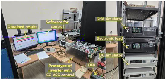
Figure 19.
Experimental platform based on the developed prototype with CC-VSG control.
In addition, the comparison of the obtained results with the commercial hybrid inverter (Sb = 5 kVA) was performed (Figure 20). A hybrid inverter has two inputs: one for photovoltaic (PV) modules and one for a battery. In addition, these two inputs must be connected simultaneously for the hybrid inverter to operate in stand-alone mode. This inverter allows us to combine PV source and battery source on a single DC bus, which in the test scheme are reproduced with the corresponding DC sources. At the same time, the hybrid inverter during the grid-connected mode operates as a grid-following (grid-tie) inverter, and when the external grid is disconnected, it operates as a stand-alone inverter. The stand-alone inverter is widely known in practice and is the simplest approach to the implementation of the grid-forming inverter. It can provide the voltage and frequency references for an isolated microgrid, but without the possibility of their flexible regulation. As disturbances leading to an increase in the inverter output current, a voltage sag at the PCC during grid-connected operation and an increase in the load in the stand-alone mode are considered. Moreover, to confirm the properties of the grid-forming inverter of the modified CC-VSG algorithm in comparison with the commercial hybrid inverter, the transition to the stand-alone operation was additionally considered.
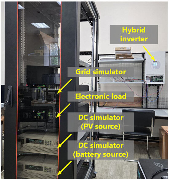
Figure 20.
Experimental platform based on the commercial hybrid inverter.
4.1. Experimental Test #1: A Voltage Sag During Grid-Connected Operation for the Proposed CC-VSG with the CSA
Only the developed experimental prototype of the inverter with the CC-VSG and the CSA is considered during the grid-connected operation. This is due to the fact that the hybrid inverter in the stand-alone mode with standard settings does not assume the operation of a VC in its control system. Therefore, the hybrid inverter does not respond to grid voltage changes until the disconnection from the protection algorithms. A voltage sag is reproduced by changing the setpoint of the RMS phase voltage on the grid simulator from 220 V to 200 V. The experimental results are shown in Figure 21.
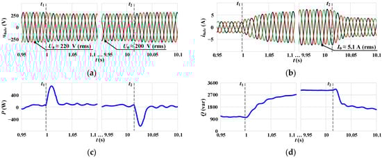
Figure 21.
Waveforms for the developed prototype with CC-VSG control under grid voltage changes: (a) instantaneous three-phase voltages at the PCC, (b) instantaneous three-phase output currents, (c) inverter output active power, and (d) inverter output reactive power.
As can be seen from the obtained waveforms, during voltage sag at t1 = 1 s (Figure 21a), there is an increase in the output current and CSA operation (Figure 21b). Moreover, the current has a sinusoidal form and predominantly reactive character, which follows from the waveform of reactive power (Figure 21d). The CSA reference value in this experiment is set equal to Imax = 0.35 pu, which corresponds to the RMS output current of the inverter equal to 3.2 A. The capacitor current of the output LC filter at the obtained voltage level is ICf = ωb · Cf · U0 = 1.9 A. Summing up the RMS inverter output current should be about 5.1 A, which coincides with the obtained waveforms. When the grid voltage is restored at t2 = 10 s, there is a gradual transition from the current-limiting mode. Thus, the obtained results confirm the stable synchronous operation of the CC-VSG with the grid in the current-limiting mode and when transitioning out of it without negative effects.
4.2. Experimental Test #2: A Voltage Sag During Grid-Connected Operation and Specified Active Power Reference for the Proposed CC-VSG with the CSA
In order to confirm the compliance of the experimental verification results for the developed prototype with the analytical curves obtained in Section 2.2, an additional experiment was performed. In this experiment, a grid voltage sag from 220 V to 187 V (from 1 pu to 0.85 pu) was reproduced with specified Pref = 0.34 pu and Imax = 0.35 pu for the developed experimental prototype. To obtain the power angle δ using DFR, the waveforms of instantaneous values for three-phase voltages of the grid simulator were also recorded. The following assumptions were made: (1) Rg and Rv were excluded, (2) Lv = 0.1 pu was set, and (3) a voltage controller (Figure 11) was changed to a reactive power controller [9]. This allows us to obtain the most reliable results necessary only for the correct comparison with analytical curves, where certain assumptions are also made, as described in detail earlier in Section 2. The experimental results for the inverter output active power and the power angle are shown in Figure 22.
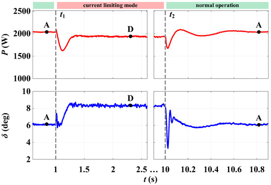
Figure 22.
Waveforms for the developed prototype with CC-VSG control during voltage sag at t1 = 1 s and voltage restoration at t2 = 10 s.
The results of the experimental and analytical data can be most accurately compared during normal steady-state operation (point A in Figure 22, by analogy with the curves in Figure 10) and steady state in the current-limiting mode (point D in Figure 22). The values obtained, taking into account the specified parameters of the test scheme, control algorithm settings, and the disturbance magnitude, are given in Table 4. As can be seen from Table 4, the results obtained coincide closely. Differences in the values of the output active power and the power angle are due to the assumptions made and measurement errors.
Table 4.
Comparison of experimental and analytical data.
4.3. Experimental Test #3: Synchronization and Transition to Stand-Alone Mode for the CC-VSG Prototype and the Hybrid Inverter
A sequence of events including (1) synchronization of the inverter with the grid, (2) inverter transition to the stand-alone operation with load supply, (3) load disconnection, and (4) load connection is considered as the next experiment. The obtained results for the developed inverter with the CC-VSG and CSA are shown in Figure 23a, and for the hybrid inverter—in Figure 23b.
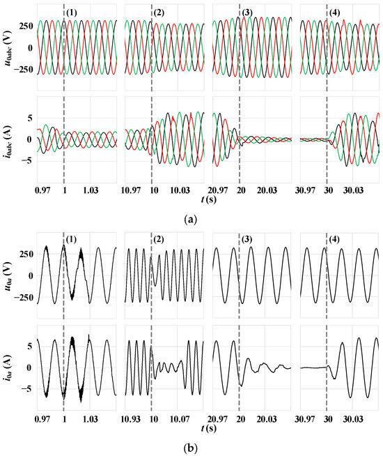
Figure 23.
Waveforms of instantaneous voltages and currents for (a) the developed inverter with the CC-VSG and CSA, and (b) the hybrid inverter.
The synchronization process (event (1) in Figure 23) of the developed and hybrid inverters is based on different mechanisms. In the first case the swing equation is used, and in the second case the PLL controller is used. Despite the quantitative differences in the obtained waveforms, in general the transient process is without negative phenomena in both cases. The transients for both inverters at events (3) and (4) also have quantitative differences, but qualitatively the process is similar. Thus, the developed CC-VSG algorithm provides reliable synchronization with the external grid and forms voltage and frequency references in the stand-alone mode similarly to a traditional hybrid inverter. The fundamental difference occurs at event (2) in the case of the external grid disconnection and transition to the stand-alone operation of the microgrid. In this case, the hybrid inverter switches from a grid-following inverter to a stand-alone inverter, resulting in the dead time and the load current loss. On the contrary, the inverter with the CC-VSG operates only as a grid-forming inverter, regardless of external operating conditions. This ensures a seamless transition to the stand-alone mode while maintaining the load power supply.
4.4. Experimental Test #4: Change in R-Load During Stand-Alone Mode for the Proposed CC-VSG with the CSA and the Hybrid Inverter
In the last experiment, the stand-alone operation is considered, in which there is a step increase in the resistive load in the grid from 150 Ohms to 80 Ohms and then a return to the initial value. The obtained waveforms for the developed inverter and hybrid inverter are shown in Figure 24. When the load increases at t1 = 1 s, the CSA within the CC-VSG operates and current limiting occurs, followed by a voltage sag up to 200 V (Figure 24a). The CSA reference in this case is also set equal to Imax = 0.35 pu, which corresponds to 3.2 A. The capacitor current is also ICf = 1.9 A. At the same time, the current right at the inverter terminals has a predominantly active character, which can be seen from the waveform of active power (Figure 24a). Taking into account this fact, already by vector addition the resulting RMS current I0 = 2.6 A is obtained, which coincides with the value obtained in the waveform of three-phase currents (Figure 24a). At t2 = 1 s, the load returns to the initial value, and there is a transition out of the limiting mode and restoration of the grid voltage to the VC reference (equal to 220 V for phase voltages). As a result, throughout the experiment, the inverter with the CC-VSG and the CSA provided stable operation of the microgrid and a reliable supply to the load. The latter confirms the efficiency and reliability of the proposed modified CC-VSG structure with the CSA.
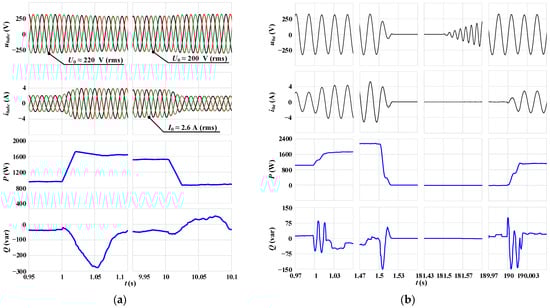
Figure 24.
Experimental results obtained under load changes in stand-alone operation for (a) developed inverter with the CC-VSG and CSA, and (b) hybrid inverter.
In the case of a commercial hybrid inverter, the situation is different. As the load increases, the inverter output current also increases (Figure 24b). However, the hybrid inverter as a stand-alone inverter has the behavior of an ideal voltage source. Therefore, the inverter tends to maintain the grid voltage according to the reference value without the possibility of regulating it. When the current increases, the voltage level does not change. The inability to maintain voltage level leads to the hybrid inverter disconnection and loss of load power supply after 0.5 s. Analysis of the algorithms for the hybrid inverter shows that it is infeasible to prevent its tripping during overload in the stand-alone mode and switch to the current-limiting mode. At the same time, depending on the value of the overload, the hybrid inverter may trip with a delay. Nevertheless, this is not acceptable due to the increasing importance of system services assigned to the grid-forming inverters in modern power systems. After a load decrease and a programmed pause (about 180 s), the hybrid inverter is restarted and the load power supply is restored (Figure 24b).
5. Conclusions
This paper presents the results of the CSA development for a modified CC-VSG structure. Taken together, the proposed algorithm refers to hybrid current limiting methods. Using a simple limiter as part of the inner current control loop, the amplitude of the reference signal is limited. The current phase is controlled by the output signals of the virtual synchronous machine equations due to the preservation of the voltage feedback in the current-limiting mode.
Theoretical analysis and simulation results have proven the effectiveness of the developed approach compared to the traditional VSG with the CSA. It has been found that the traditional VSG with the CSA has a stable operating range between 9.8° < φlim < 77.4°. For the developed algorithm, the current phase φ is not limited—up to 0–180°. At the same time, both algorithms ensure stable operation with a voltage sag up to 0.75 pu. More severe voltage sags were not considered, since in this case LVRT logic should operate. This is a topic for a future work. It should be noted that for the developed algorithm, the stability in the current-limiting mode is determined by the voltage sag, the grid impedance, and the Imax setting (Lg∙Imax < Ug). The modification of the proposed algorithm for its application in ultra-weak grids with Lg = 1 pu is a future work.
To prevent saturation of the VC in the current-limiting mode and ensure reliable exit from it, it is proposed to use a simple blocking algorithm. This algorithm blocks the VC based on a signal from the current limiter. The results of adding the proposed algorithm demonstrated a five-second reduction in the overvoltage, which occurs due to integrator saturation. A comparison with conditional integration also showed that the use of a limiter for the input voltage signal prevents lock-up in the limiting mode.
Experimental verification is carried out for the developed prototype of the inverter with the proposed CC-VSG algorithm and CSA. A commercial hybrid inverter was also used to compare and assess the performance of the CC-VSG. The results showed that the developed algorithm eliminates the dead time when the external grid is disconnected. At the same time, the dead time for the hybrid inverter was about 7 ms. Furthermore, when the resistive load was changed to 80 Ohms, the hybrid inverter tripped after 0.5 s due to overload. In contrast, the developed prototype continued to operate and supply power to the load.
Author Contributions
Conceptualization, A.A.; Methodology, A.A. and A.S.; Formal analysis, P.I.; Software, I.G. and Y.B.; Investigation, P.R. and V.K.; Validation, Y.B. and V.K.; Resources, A.S.; Supervision, P.I. and A.S.; Funding acquisition, A.S.; Writing—original draft, A.A. and A.S.; Writing—review and editing, P.R. and P.I. All authors have read and agreed to the published version of the manuscript.
Funding
The reported study was funded by the Russian Science Foundation, project number 24-29-00004.
Data Availability Statement
The data presented in this study are available on request from the corresponding author. The data are not publicly available due to privacy restrictions.
Conflicts of Interest
The authors declare no conflicts of interest.
Appendix A
Table A1.
Main grid and inverter parameters.
Table A1.
Main grid and inverter parameters.
| Parameter | Value | Parameter | Value | Parameter | Value |
|---|---|---|---|---|---|
| Uac,b | 380 V | Rg | 0.06 pu | KFF | 10 pu |
| Udc,b | 700 V | Lg | 0.2 pu | Uset | 1 pu |
| Sb | 6 kW | Lv | 0.2 pu | KU | 1 pu |
| fb | 50 Hz | Rv | 0.1 pu | fsw | 4 kHz |
| Lf | 0.16 pu | Kw | 25 pu | Imax | 0.9 pu |
| Cf | 0.2268 pu | HVSG | 2 s | Rload | 30.723 Ohm |
References
- Kroposki, B.; Johnson, B.; Zhang, Y.; Gevorgian, V.; Denholm, P.; Hodge, B.-M.; Hannegan, B. Achieving a 100% Renewable Grid: Operating Electric Power Systems with Extremely High Levels of Variable Renewable Energy. IEEE Power Energy Mag. 2017, 15, 61–73. [Google Scholar] [CrossRef]
- Baier, C.R.; Melin, P.E.; Torres, M.A.; Ramirez, R.O.; Muñoz, C.; Quinteros, A. Developing and Evaluating the Operating Region of a Grid-Connected Current Source Inverter from Its Mathematical Model. Mathematics 2024, 12, 1775. [Google Scholar] [CrossRef]
- Ilyushin, P.V.; Shepovalova, O.V.; Filippov, S.P.; Nekrasov, A.A. Calculating the Sequence of Stationary Modes in Power Distribution Networks of Russia for Wide-Scale Integration of Renewable Energy Based Installations. Energy Rep. 2021, 7, 308–327. [Google Scholar] [CrossRef]
- Hatziargyriou, N.; Milanovic, J.; Rahmann, C.; Ajjarapu, V.; Canizares, C.; Erlich, I.; Hill, D.; Hiskens, I.; Kamwa, I.; Pal, B.; et al. Definition and Classification of Power System Stability—Revisited & Extended. IEEE Trans. Power Syst. 2021, 36, 3271–3281. [Google Scholar] [CrossRef]
- Wang, J.; Ganguly, S.; Kroposki, B. Performance Evaluation of Multi-Vendor Grid-Forming Inverters for Grid-Connected Operation Through Hardware Experimentation. In Proceedings of the 2024 IEEE/PES Transmission and Distribution Conference and Exposition (T&D), Anaheim, CA, USA, 6–9 May 2024; pp. 1–5. [Google Scholar] [CrossRef]
- Tozak, M.; Taskin, S.; Sengor, I.; Hayes, B.P. Modeling and Control of Grid Forming Converters: A Systematic Review. IEEE Access 2024, 12, 107818–107843. [Google Scholar] [CrossRef]
- Wang, Y.; Ji, H.; Luo, R.; Liu, B.; Wu, Y. Energy Optimization Strategy for Wind–Solar–Storage Systems with a Storage Battery Configuration. Mathematics 2025, 13, 1755. [Google Scholar] [CrossRef]
- Milano, F.; Dörfler, F.; Hug, G.; Hill, D.J.; Verbič, G. Foundations and Challenges of Low-Inertia Systems (Invited Paper). In Proceedings of the 2018 Power Systems Computation Conference (PSCC), Dublin, Ireland, 11–15 June 2018; pp. 1–25. [Google Scholar] [CrossRef]
- Suvorov, A.; Askarov, A.; Kievets, A. A Freely Configurable Structure of Virtual Synchronous Generator for Grid-Forming Converters. Electr. Eng. 2023, 105, 1331–1345. [Google Scholar] [CrossRef]
- Rathnayake, D.B.; Akrami, M.; Phurailatpam, C.; Me, S.P.; Hadavi, S.; Jayasinghe, G.; Zabihi, S.; Bahrani, B. Grid Forming Inverter Modeling, Control, and Applications. IEEE Access 2021, 9, 114781–114807. [Google Scholar] [CrossRef]
- Baeckeland, N.; Chatterjee, D.; Lu, M.; Johnson, B.; Seo, G.-S. Overcurrent Limiting in Grid-Forming Inverters: A Comprehensive Review and Discussion. IEEE Trans. Power Electron. 2024, 39, 14493–14517. [Google Scholar] [CrossRef]
- Fan, B.; Liu, T.; Zhao, F.; Wu, H.; Wang, X. A Review of Current-Limiting Control of Grid-Forming Inverters Under Symmetrical Disturbances. IEEE Open J. Power Electron. 2022, 3, 955–969. [Google Scholar] [CrossRef]
- Lu, M.; Mallik, R.; Johnson, B.; Dhople, S. Dispatchable Virtual-Oscillator-Controlled Inverters with Current-Limiting and MPPT Capabilities. In Proceedings of the 2021 IEEE Energy Conversion Congress and Exposition (ECCE), Vancouver, BC, Canada, 10–14 October 2021; pp. 3316–3323. [Google Scholar] [CrossRef]
- Du, W.; Nguyen, Q.; Liu, Y.; Mohiuddin, S.M. A Current Limiting Control Strategy for Single-Loop Droop-Controlled Grid-Forming Inverters Under Balanced and Unbalanced Faults. In Proceedings of the 2022 IEEE Energy Conversion Congress and Exposition (ECCE), Detroit, MI, USA, 9–13 October 2022; pp. 1–7. [Google Scholar] [CrossRef]
- Du, W.; Mohiuddin, S.M. A Two-Stage Current Limiting Control Strategy for Improved Low-Voltage Ride-Through Capability of Direct-Droop-Controlled, Grid-Forming Inverters. In Proceedings of the 2023 IEEE Energy Conversion Congress and Exposition (ECCE), Nashville, TN, USA, 29 October–2 November 2023; pp. 2886–2890. [Google Scholar] [CrossRef]
- Bottrell, N.; Green, T.C. Comparison of Current-Limiting Strategies During Fault Ride-Through of Inverters to Prevent Latch-Up and Wind-Up. IEEE Trans. Power Electron. 2014, 29, 3786–3797. [Google Scholar] [CrossRef]
- Brucoli, M.; Green, T.C.; McDonald, J.D.F. Modelling and Analysis of Fault Behaviour of Inverter Microgrids to Aid Future Fault Detection. In Proceedings of the 2007 IEEE International Conference on System of Systems Engineering, San Antonio, TX, USA, 16–18 April 2007; pp. 1–6. [Google Scholar] [CrossRef]
- Baghaee, H.R.; Mirsalim, M.; Gharehpetian, G.B.; Talebi, H.A. A New Current Limiting Strategy and Fault Model to Improve Fault Ride-through Capability of Inverter Interfaced DERs in Autonomous Microgrids. Sustain. Energy Technol. Assess. 2017, 24, 71–81. [Google Scholar] [CrossRef]
- Sadeghkhani, I.; Hamedani Golshan, M.E.; Guerrero, J.M.; Mehrizi-Sani, A. A Current Limiting Strategy to Improve Fault Ride-Through of Inverter Interfaced Autonomous Microgrids. IEEE Trans. Smart Grid 2017, 8, 2138–2148. [Google Scholar] [CrossRef]
- Zhang, L.; Harnefors, L.; Nee, H.-P. Power-Synchronization Control of Grid-Connected Voltage-Source Converters. IEEE Trans. Power Syst. 2010, 25, 809–820. [Google Scholar] [CrossRef]
- Khayat, Y.; Chen, P.; Bongiorno, M.; Johansson, B.; Majumder, R. FRT Capability of Grid-Forming Power Converters: An Antiwindup Scheme. IEEE Trans. Power Electron. 2024, 39, 12842–12855. [Google Scholar] [CrossRef]
- Barsali, S.; Ceraolo, M.; Pelacchi, P.; Poli, D. Control Techniques of Dispersed Generators to Improve the Continuity of Electricity Supply. In Proceedings of the 2002 IEEE Power Engineering Society Winter Meeting, New York, NY, USA, 27–31 January 2002; Volume 2, pp. 789–794. [Google Scholar] [CrossRef]
- Huang, L.; Xin, H.; Wang, Z.; Wu, K.; Wang, H.; Hu, J.; Lu, C. A Virtual Synchronous Control for Voltage-Source Converters Utilizing Dynamics of DC-Link Capacitor to Realize Self-Synchronization. IEEE J. Emerg. Sel. Top. Power Electron. 2017, 5, 1565–1577. [Google Scholar] [CrossRef]
- Saffar, K.G.; Driss, S.; Ajaei, F.B. Impacts of Current Limiting on the Transient Stability of the Virtual Synchronous Generator. IEEE Trans. Power Electron. 2023, 38, 1509–1521. [Google Scholar] [CrossRef]
- Rokrok, E.; Qoria, T.; Bruyere, A.; Francois, B.; Guillaud, X. Transient Stability Assessment and Enhancement of Grid-Forming Converters Embedding Current Reference Saturation as Current Limiting Strategy. IEEE Trans. Power Syst. 2022, 37, 1519–1531. [Google Scholar] [CrossRef]
- Zhao, X.; Flynn, D. Freezing Grid-Forming Converter Virtual Angular Speed to Enhance Transient Stability Under Current Reference Limiting. In Proceedings of the 2020 IEEE 21st Workshop on Control and Modeling for Power Electronics (COMPEL), Aalborg, Denmark, 9–12 November 2020; pp. 1–7. [Google Scholar] [CrossRef]
- Chen, J.; Prystupczuk, F.; O’Donnell, T. Use of Voltage Limits for Current Limitations in Grid-Forming Converters. CSEE J. Power Energy Syst. 2020, 6, 259–269. [Google Scholar] [CrossRef]
- Zhou, J.Z.; Ding, H.; Fan, S.; Zhang, Y.; Gole, A.M. Impact of Short-Circuit Ratio and Phase-Locked-Loop Parameters on the Small-Signal Behavior of a VSC-HVDC Converter. IEEE Trans. Power Deliv. 2014, 29, 2287–2296. [Google Scholar] [CrossRef]
- Askarov, A.; Bay, Y.; Ufa, R.; Radko, P.; Ilyushin, P.; Suvorov, A. Signatures and Mechanism Analysis of Converter-Grid Subsynchronous Oscillations. Mathematics 2024, 12, 3884. [Google Scholar] [CrossRef]
- Li, Z.; Hu, J.; Chan, K.W. A New Current Limiting and Overload Protection Scheme for Distributed Inverters in Microgrids Under Grid Faults. IEEE Trans. Ind. Appl. 2021, 57, 6362–6374. [Google Scholar] [CrossRef]
- Lu, X.; Wang, J.; Guerrero, J.M.; Zhao, D. Virtual-Impedance-Based Fault Current Limiters for Inverter Dominated AC Microgrids. IEEE Trans. Smart Grid 2018, 9, 1599–1612. [Google Scholar] [CrossRef]
- Erdocia, J.; Urtasun, A.; Marroyo, L. Dual Voltage–Current Control to Provide Grid-Forming Inverters With Current Limiting Capability. IEEE J. Emerg. Sel. Top. Power Electron. 2022, 10, 3950–3962. [Google Scholar] [CrossRef]
- Baeckeland, N.; Seo, G.-S. Novel Hybrid Current Limiter for Grid-Forming Inverter Control During Unbalanced Faults. In Proceedings of the 2023 11th International Conference on Power Electronics and ECCE Asia (ICPE 2023—ECCE Asia), Jeju Island, Republic of Korea, 22–25 May 2023; pp. 1517–1522. [Google Scholar] [CrossRef]
- Rosso, R.; Engelken, S.; Liserre, M. On The Implementation of an FRT Strategy for Grid-Forming Converters Under Symmetrical and Asymmetrical Grid Faults. IEEE Trans. Ind. Appl. 2021, 57, 4385–4397. [Google Scholar] [CrossRef]
- Qoria, T.; Gruson, F.; Colas, F.; Kestelyn, X.; Guillaud, X. Current Limiting Algorithms and Transient Stability Analysis of Grid-Forming VSCs. Electr. Power Syst. Res. 2020, 189, 106726. [Google Scholar] [CrossRef]
- Lyu, X.; Du, W.; Mohiuddin, S.M.; Nandanoori, S.P.; Elizondo, M. Criteria for Grid-Forming Inverters Transitioning Between Current Limiting Mode and Normal Operation. IEEE Trans. Power Syst. 2024, 39, 6107–6110. [Google Scholar] [CrossRef]
- Ghoshal, A.; John, V. Anti-windup schemes for proportional integral and proportional resonant controller. In Proceedings of the National Power Electronic Conference, Roorkee, India, 10–13 June 2010; pp. 1–6. [Google Scholar]
- Teodorescu, R.; Blaabjerg, F.; Borup, U.; Liserre, M. A New Control Structure for Grid-Connected LCL PV Inverters with Zero Steady-State Error and Selective Harmonic Compensation. In Proceedings of the Nineteenth Annual IEEE Applied Power Electronics Conference and Exposition, APEC’04, Anaheim, CA, USA, 22–26 February 2004; Volume 1, pp. 580–586. [Google Scholar] [CrossRef]
- D’Arco, S.; Suul, J.A.; Fosso, O.B. Control System Tuning and Stability Analysis of Virtual Synchronous Machines. In Proceedings of the 2013 IEEE Energy Conversion Congress and Exposition, Denver, CO, USA, 15–19 September 2013; pp. 2664–2671. [Google Scholar] [CrossRef]
- Yuan, H.; Yuan, X.; Hu, J. Modeling of Grid-Connected VSCs for Power System Small-Signal Stability Analysis in DC-Link Voltage Control Timescale. IEEE Trans. Power Syst. 2017, 32, 3981–3991. [Google Scholar] [CrossRef]
- Wu, H.; Wang, X. Design-Oriented Transient Stability Analysis of Grid-Connected Converters With Power Synchronization Control. IEEE Trans. Ind. Electron. 2019, 66, 6473–6482. [Google Scholar] [CrossRef]
- Kkuni, K.V.; Yang, G. Effects of Current Limit for Grid Forming Converters on Transient Stability: Analysis and Solution. Int. J. Electr. Power Energy Syst. 2024, 158, 109919. [Google Scholar] [CrossRef]
- Xin, H.; Huang, L.; Zhang, L.; Wang, Z.; Hu, J. Synchronous Instability Mechanism of P-f Droop-Controlled Voltage Source Converter Caused by Current Saturation. IEEE Trans. Power Syst. 2016, 31, 5206–5207. [Google Scholar] [CrossRef]
- Orihara, D.; Taoka, H.; Kikusato, H.; Hashimoto, J.; Otani, K.; Khaliqur, R.; Ustun, T.S. Theoretical Comparison of Current Limiting Algorithms in Grid-Forming Inverter in Terms of Transient Stability. IEEE Open J. Power Electron. 2025, 6, 109–119. [Google Scholar] [CrossRef]
- Askarov, A.; Rudnik, V.; Ruban, N.; Radko, P.; Ilyushin, P.; Suvorov, A. Enhanced Virtual Synchronous Generator with Angular Frequency Deviation Feedforward and Energy Recovery Control for Energy Storage System. Mathematics 2024, 12, 2691. [Google Scholar] [CrossRef]
- Mallemaci, V.; Mandrile, F.; Carpaneto, E.; Bojoi, R. Simplified Virtual Synchronous Compensator With Grid–Forming Capability. IEEE Trans. Ind. Appl. 2023, 59, 6203–6219. [Google Scholar] [CrossRef]
- Askarov, A.; Ruban, N.; Bay, Y.; Ufa, R.; Malkova, Y.; Suvorov, A. A Feedforward Control for Increasing the Damping Effect of Enhanced Current-Controlled Virtual Synchronous Generator. Electr. Power Syst. Res. 2024, 234, 110659. [Google Scholar] [CrossRef]
- Gkountaras, A.; Dieckerhoff, S.; Sezi, T. Evaluation of Current Limiting Methods for Grid Forming Inverters in Medium Voltage Microgrids. In Proceedings of the 2015 IEEE Energy Conversion Congress and Exposition (ECCE), Montreal, QC, Canada, 20–24 September 2015; pp. 1223–1230. [Google Scholar] [CrossRef]
- He, X.; Desai, M.A.; Huang, L.; Dörfler, F. Cross-Forming Control and Fault Current Limiting for Grid-Forming Inverters. IEEE Trans. Power Electron. 2025, 40, 3980–4007. [Google Scholar] [CrossRef]
- Akagi, H.; Watanabe, E.H.; Aredes, M. Instantaneous Power Theory and Applications to Power Conditioning; Wiley IEEE Press: Hoboken, NJ, USA, 2007. [Google Scholar]
- Suvorov, A.; Askarov, A.; Ruban, N.; Rudnik, V.; Radko, P.; Achitaev, A.; Suslov, K. An Adaptive Inertia and Damping Control Strategy Based on Enhanced Virtual Synchronous Generator Model. Mathematics 2023, 11, 3938. [Google Scholar] [CrossRef]
- Aragon, D.; Unamuno, E.; Ceballos, S.; Barrena, J. Comparative small-signal evaluation of advanced grid-forming control techniques. Electr. Power Syst. Res. 2022, 211, 108154. [Google Scholar] [CrossRef]
- Ilyushin, P.V.; Shepovalova, O.V.; Filippov, S.P.; Nekrasov, A.A. The Effect of Complex Load on the Reliable Operation of Solar Photovoltaic and Wind Power Stations Integrated into Energy Systems and into Off-Grid Energy Areas. Energy Rep. 2022, 8, 1515–1529. [Google Scholar] [CrossRef]
- Yuan, M.; Chen, L.; Min, Y.; Gao, P.; Tan, B.; Wang, M. Lock-Up Problem in the Current-Limiting Mode of the Grid-Forming Converter with Priority-Based Limiter and Its Solution. IET Gener. Transm. Distrib. 2025, 19, e70052. [Google Scholar] [CrossRef]


Disclaimer/Publisher’s Note: The statements, opinions and data contained in all publications are solely those of the individual author(s) and contributor(s) and not of MDPI and/or the editor(s). MDPI and/or the editor(s) disclaim responsibility for any injury to people or property resulting from any ideas, methods, instructions or products referred to in the content. |
© 2025 by the authors. Licensee MDPI, Basel, Switzerland. This article is an open access article distributed under the terms and conditions of the Creative Commons Attribution (CC BY) license (https://creativecommons.org/licenses/by/4.0/).