1. Mathematical Formulation of Resonance Self-Shielding
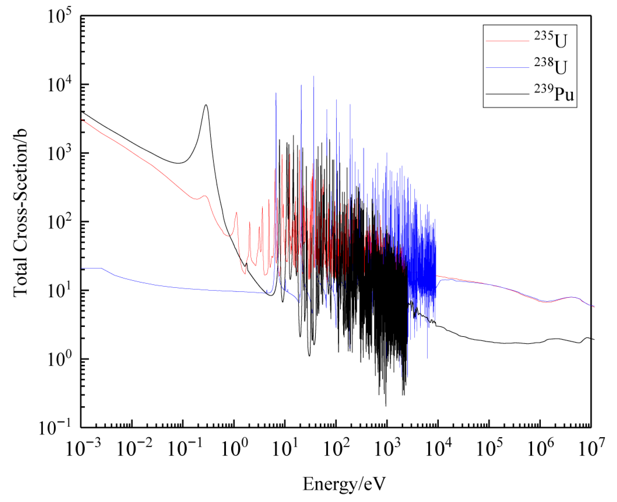
The neutron transport equation, fundamentally an integro-differential equation describing the spatial, energy, and angular distribution of neutrons in a medium, stands as the mathematical cornerstone of nuclear reactor physics. Its solution is pivotal for determining key physical quantities such as neutron flux, power distribution, and reactivity, which are critical for reactor design and safety assessment. However, solving this equation poses immense computational challenges: spatially, a reactor core may involve millions of discrete regions, while energetically, the continuous neutron energy spectrum (spanning from MeV to meV) requires fine discretization to capture nuclide-specific reaction characteristics, which is shown in
Figure 1. This high-dimensionality (space + energy + angle) and the need for precision make direct rigorous solutions computationally prohibitive, necessitating approximated deterministic methods with trade-offs between accuracy and efficiency [
1].
Within the resonance energy range (typically 1 eV to 10 keV), the mathematical complexity intensifies due to the highly nonlinear behavior of microscopic cross-sections. For heavy nuclides such as
235U and
238U, cross-sections exhibit sharp, discontinuous resonance peaks—manifestations of metastable compound nucleus formation—leading to orders-of-magnitude variations over narrow energy intervals. This extreme nonlinearity induces corresponding “valleys” in the neutron flux spectrum (resonance self-shielding in energy) and spatial flux depression (spatial self-shielding), both reflecting the strong coupling between cross-sections and flux in the transport equation. Such behavior renders conventional multi-group approximations inadequate, as equivalent cross-sections become strongly spectrum dependent, as shown in Equation (1), demanding more sophisticated mathematical treatments.
where σ
g(E) is the micro cross-section of group g for energy E, ϕ is the neutron flux, Ω represents the angle, and r represents the region.
A further critical challenge arises in multi-resonant-nuclide systems (e.g., MOX fuels containing U and Pu isotopes), where overlapping resonance peaks of different nuclides induce resonance interference. Mathematically, this interference transforms the total cross-section into a coupled function: Σt(E) = Σr1(E) + Σr2(E) + … + Σm, where each Σrj(E) is a nonlinear function of energy. Consequently, the calculation of effective resonance cross-sections evolves from a problem of independent single-nuclide approximation to a complex multivariate function fitting task: σeff,x = f(σb, {Nr}, {σr(E)}), where σb is the background cross-section, Nr are nuclide densities, and σr(E) are nuclide-specific resonance cross-sections. Traditional methods, such as the Bondarenko iteration method (BIM) or resonance interference factor method (RIFM), struggle here: BIM relies on iterative updates of nuclide cross-sections, leading to time-consuming convergence issues and limited accuracy in capturing strong couplings; RIFM introduces empirical correction factors, compromising efficiency and generality.
Due to the presence of numerous heavy nuclei with resonance cross-sections, the neutron flux distribution in reactors exhibits complex resonance self-shielding phenomena in both energy and spatial dimensions. Therefore, the calculation of equivalent multi-group cross-sections for resonant nuclides in the resonance energy range, or resonance calculation, is a challenge in reactor physics calculations. The accuracy of resonance calculations directly affects the solution of the neutron transport equation, thereby impacting the entire reactor physics calculation process. With the development of nuclear energy utilization, the material composition and structural design within reactors are becoming increasingly complex. As the foundation of reactor physics calculations, equivalent multi-group cross-sections are becoming increasingly important. Consequently, how to perform resonance calculations efficiently and with high precision has become a major focus in the international reactor physics calculation field. Resonance calculation theory was proposed in the 1960s. After more than fifty years of development, numerous methods have been studied and applied in engineering practice. Overall, these methods can be divided into the following three categories: (1) The ultra-fine group method [
2,
3]: It is broadly defined as using ultra-fine energy group structures in multi-group transport calculations to make multi-group cross-sections approximate continuous-energy cross-sections. This was actually the commonly used method in the early stages of reactor physics calculation research to obtain benchmark solutions for multi-group transport calculations. The disadvantage of the ultra-fine group method is its unsuitability for complex geometries, as calculating the first collision probability for neutrons in complex geometries is highly time-consuming [
4]. Therefore, the ultra-fine group method used in current reactor physics calculation programs is only applied to homogeneous problems and simple cell problems. (2) The equivalence theory method [
5,
6,
7]: This method is based on the Bondarenko model, and the calculation of multi-group cross-sections relies on the narrow resonance assumption. Neutrons within the resonance peak come from scattering outside the peak, making the spectrum in the resonance energy region approximately a 1/E spectrum. In homogeneous problems, the resonance intensity of resonant nuclides under different moderating conditions can be simulated using this approximate spectrum, and then the resonance cross-sections of resonant nuclides are obtained according to Formula (1). However, with the expansion of the two-step method application, i.e., performing one-time calculations at the assembly level, equivalence theory faces many limitations in geometric processing capability and accuracy. (3) The subgroup method [
8,
9,
10]: Generally, neutron flux density is inversely proportional to the macroscopic total cross-section of the material. In energy ranges where cross-sections exhibit resonance peaks, corresponding “valleys” in flux exist. This phenomenon indicates that the division of energy groups in the neutron transport equation need not follow the energy dimension. Instead, it can be divided based on the amplitude of the cross-section peaks. Dividing subgroups in this way ensures that the variation in neutron flux within a subgroup is smaller than in traditional energy-based group division. Simultaneously, the resonance intensity within subgroups is smaller, ensuring the stability of the subgroup method. Typically, dividing into several subgroups can yield sufficiently accurate results. Due to its strong geometric adaptability and high computational accuracy, the subgroup method has developed rapidly in recent years and is widely used in high-fidelity full-core calculation programs using the one-step method [
11,
12,
13].
However, the derivation process of the subgroup method is based on the assumption that only one resonant nuclide exists in the calculation system. In actual reactor fuel, the coexistence of multiple resonant nuclides causes resonance peaks to overlap, forming resonance interference effects. The spectral fluctuations under resonance interference conditions are more complex, and effective resonance cross-section calculations become more difficult. The most classical approach for handling resonance interference is the Bondarenko iteration method (BIM) [
14]. When calculating the current resonant nuclide, this method uses assumed initial values for the cross-sections of other resonant nuclides, then updates the original initial cross-sections using the calculated resonance cross-sections. This process is repeated for all resonant nuclides, updating the effective resonance cross-sections of all resonant nuclides until convergence. The Bondarenko iteration method is widely used in subgroup methods and equivalence theory methods, but it cannot accurately consider the flux depression caused by overlapping resonance peaks of multiple nuclides, resulting in low computational accuracy. Simultaneously, the background iteration method requires multiple iterative calculations for all resonant nuclides, leading to low computational efficiency. To improve the computational efficiency of the background iteration method, the HELIOS program [
15] proposed the resonance classification concept. This method categorizes resonant nuclides into several types based on the shape of their resonance peaks, and resonance calculations are performed for each category’s representative nuclide. Resonance classification increases calculation speed but further reduces accuracy.
Sohail et al. [
16] and William [
17] proposed an interference treatment method based on correction factors, called the resonance interference factor method (RIFM). This method establishes a correspondence between multi-resonant-nuclide coexistence and single-resonant-nuclide problems based on ultra-fine-group methods or Monte Carlo methods. The interference factor is the ratio of the resonance cross-section considering the resonance interference effect to the single-resonant-nuclide cross-section. Multiplying the resonance cross-section directly calculated by the subgroup method by the interference factor corrects for the resonance interference effect. However, calculating the interference factor requires calling ultra-fine-group or Monte Carlo programs, making the process complex and inefficient. Peng et al. [
18] improved the RIFM by proposing a rapid method for generating interference factor tables. Takeda et al. [
19] proposed the conditional probability method, which analyzes resonance peak variation curves to find the overlap probability of subgroup cross-section energy intervals for different resonant nuclides and generates subgroup parameters based on this probability. The conditional probability method requires graphical calculation of probability values, resulting in low computational efficiency. Huang et al. [
20] proposed the stochastic interference approximation method to approximately solve the conditional probability, avoiding the graphical process. Hébert et al. [
21] proposed an extended Ribon subgroup calculation model using a correlation model approach to handle resonance interference effects. This method solves the slowing-down equation under two resonant nuclide conditions, solving the interference effect matrix between resonant nuclides while defining cross-section moments, and then uses this matrix to account for interference effects during subgroup calculations. The core idea of both the conditional probability method and the correlation model method is to find overlapping energy intervals of subgroups for different nuclides, making the calculation complex and difficult to apply to situations with a large number of coexisting resonant nuclides. Kim et al. [
22] and Zhang et al. [
23] proposed resonance integral tables considering resonance interference, equating multiple resonant nuclides to a “pseudo-nuclide”. In recent years, He et al. [
24] and Liu et al. [
25,
26] proposed the subgroup pseudo-nuclide method to handle resonance interference effects. The core idea of this method is to shift the treatment of resonance interference to the subgroup parameter generation process. By solving multi-nuclide resonance problems using ultra-fine groups, it combines the effective resonance self-shielded cross-sections considering resonance interference with background cross-sections and regenerates resonance integral tables. The subgroup parameters calculated via the pseudo-nuclide resonance integral table already incorporate the influence of resonance interference, thus eliminating the need for additional correction. However, the applicability of pseudo-nuclide subgroup parameters is related to the resonance integrals. For different problems, it requires calling ultra-fine-group programs for online resonance integral calculations and considering different nuclide density ratios, temperatures, or position information, making the calculation process relatively complex.
To address these limitations, this work turns to Padé approximation, a powerful mathematical tool in rational function approximation. Unlike polynomial approximations, Padé approximants—ratios of two polynomials—excel in capturing functions with singularities, rapid variations, or sharp peaks, making them well-suited for modeling resonance cross-sections. Their success in scientific computing, from approximating nuclear data libraries to fitting response functions, motivates their application here. The core mathematical idea of this study is to explicitly model the functional relationship between fuel-equivalent cross-sections (or individual nuclide cross-sections) and background cross-sections using Padé rational functions. Based on this model, a novel subgroup parameter generation algorithm is developed, which inherently incorporates resonance interference during parameter construction, thereby avoiding the need for iterative coupling treatments.
Another process for subgroup calculation is the combining solution method for the neutron transport equation. The subgroup transport equation is consistent in format with the multigroup transport equation, so it can be coupled with any transport solution method, which has great advantages in geometric processing. The HELIOS code [
27] adopted a coupling of the subgroup method and the collision probability method in its early versions, showing high computational efficiency. Tekeda et al. [
28] also proposed a calculation strategy combining the subgroup method and the collision probability method and applied it to the core calculation of KUCA. With the development of high-fidelity calculations, the disadvantages of the collision probability method in complex geometry handling gradually emerged. Yamamoto et al. [
29] combined the subgroup method with the discrete ordinate method, mainly applied to resonance calculations of fast reactors. With the development of transport calculations, the MOC (method of characteristics) has gradually become the mainstream method for international transport calculations due to its powerful geometric processing capability, and the subgroup method is increasingly coupled with the MOC. The HELIOS-2 version [
30] uses the MOC to replace the collision probability method for solving the subgroup fixed-source equation and the multigroup transport equation. Other commonly used international commercial core calculation software, such as DeCART [
31,
32], MPACT [
33,
34,
35], and APOLLO [
36,
37], also adopt the coupled calculation of the subgroup method and the MOC. To improve the computational efficiency of the subgroup transport equation, Stimpson [
38] proposed the concept of the integrated MOC, solving the multigroup fixed-source equation simultaneously and simplifying the subgroup transport equation. Park et al. [
39] proposed an interpolation calculation method for the subgroup macroscopic removal term, reducing the number of transport solutions by interpolating the subgroup flux. Therefore, this paper employs a coupled calculation of the method of characteristics (MOC) and the subgroup method since the MOC is utilized to track particle trajectories for solving subgroup transport equations, enabling space-angle-dependent transport calculations in complex geometries. The rationale for this coupling lies in the following: MOC’s efficient handling of complex geometries and balancing calculation accuracy and engineering practicality for multi-scenario applications from engineering-level core analysis to scientific high-fidelity simulations.
The remainder of this paper is structured as follows:
Section 2 presents the mathematical formulation of the improved subgroup method, including the derivation of Padé-based cross-section models and the algorithm for solving subgroup parameters.
Section 3 details numerical experiments to validate the mathematical robustness and efficiency of the proposed method. Finally,
Section 4 and
Section 5 summarizes the conclusions and highlights the broader implications of the developed mathematical framework.
2. Padé-Based Approximation Framework for Coupled Resonance Systems
2.1. Conventional Subgroup Parameterization and Its Mathematical Limitations
In the traditional subgroup method, the process of generating subgroup parameters is based on the condition of a single resonant nuclide in a homogeneous medium. Assuming that the constituent components include the resonant nuclide R and the moderator H, the flux density spectrum of a specific resonance energy group g can be analytically derived by directly solving the slowing-down equation as follows:
where λ is the intermediate resonance factor; Σ
a and σ
a are the macro and micro absorption cross-sections, respectively; Σ
s and σ
s are the macro and micro scattering cross-sections, respectively; Σ
p and σ
p are the macro and micro potential scattering cross-sections, respectively; and σ
b is the background cross-section, which is defined as follows:
where
NR is the nuclide density of the resonant nuclide
R.
Specifically, In Equations (2) and (3), the IR approximation is based on the traditional narrow resonance (NR) approximation and Narrow Resonance Infinite Mass (NRIM) approximation: the NR approximation assumes that resonances are extremely narrow, and neutrons with energy within the resonance range that undergo scattering reactions will lose sufficient energy to escape the resonance range; the NRIM approximation only treats light scattering nuclides as narrow resonances, assuming that heavy nuclides have infinite mass, so neutrons do not lose energy when scattering with heavy nuclides; in the IR approximation, when neutrons within the resonance range scatter with nuclide i, only a fraction λi of these neutrons will escape the resonance range, and the remaining fraction 1 − λi of neutrons are assumed to lose no energy. The value of the λi parameter depends on the resonance width and the average energy loss from a single scattering reaction (related to the atomic weight of the scattering nuclide); in practical applications, all resonances of hydrogen nuclides are regarded as narrow resonances, so their λ factor is 1, and the λ factors of non-hydrogen scattering nuclides are obtained by comparing the solutions of mixtures of resonant nuclides with those of mixtures where hydrogen is partially replaced by other nuclides, converting λ into a hydrogen-equivalence parameter. When the neutron spectrum deviates significantly from the 1/E distribution, the calculation accuracy of the resonance self-shielding effect will be affected. In addition, σb is not merely a mathematical variable; in the manuscript, it represents the average neutron shielding experienced by a resonant nuclide due to all other surrounding nuclei (moderators and other absorbers), and this physical connotation indeed requires further reinforcement and elaboration. Specifically, in homogeneous problem calculations, the background cross-section equals the sum of the potential scattering cross-sections of all nuclides; in heterogeneous problem calculations, due to the complexity of geometry and nuclide distribution, the background cross-section must be derived by inverting the neutron flux density. In terms of influencing factors, the background cross-section is most significantly affected by moderating materials, because moderators typically have large potential scattering cross-sections, which play a dominant role in the neutron shielding effect of resonant nuclides. Meanwhile, the background cross-section also reflects, to a certain extent, the spectral characteristics of the location where the resonant nuclide is situated—differences in the neutron spectrum are manifested through changes in the background cross-section, which in turn affects the calculation accuracy of the resonance self-shielding effect.
After obtaining the flux spectrum, combined with the definition of subgroup parameters, the effective cross-section of the resonance energy group g can be expressed as follows:
where
σi is subgroup cross-section.
pi is the subgroup weight, which represents the probability of the neutron located in the corresponding subgroup
i of group
g. The combination of subgroup cross-sections and subgroup weights are called the subgroup parameters. By the definition by the quadrature of subgroup parameters, the integration of energy is replaced by summation of subgroups. Moreover,
I represents the number of subgroups,
Eg is the energy range of group g, and Δ
Ei is the corresponding energy range of subgroup
i.
ϕi is the flux of subgroup i, which is calculated by the following equation:
Equation (3) establishes the relationship between the effective cross-section of the resonance group, the background cross-section, subgroup cross-sections, and subgroup weights through the expression of the energy-group-averaged resonance cross-section in the form of subgroups. It can be seen that the only unknowns in Equation (4) are the subgroup cross-sections and subgroup weights. With the number of subgroups being I, the number of unknowns is 2I. The basic solution process for subgroup parameters is as follows:
- (1)
Design an infinite homogeneous problem where a single resonant nuclide is mixed with hydrogen nuclei. The background cross-section in this problem can be directly solved using Equation (3).
- (2)
Obtain the effective resonance cross-section of the single resonant nuclide under this background cross-section by interpolating the multigroup cross-section database or directly calculating it using an ultra-fine group program or a Monte Carlo program.
- (3)
Change the hydrogen nucleus density to establish infinite homogeneous problems of a single nuclide under different background cross-sections, and generate a corresponding relationship table between background cross-sections and the effective resonance cross-sections of the resonant nuclide.
- (4)
Combined with Equation (4), select 2I background cross-section points from the background cross-section table, and directly solve for the 2I subgroup parameters using numerical methods.
- (5)
Repeat the above process for different resonant nuclides to obtain the subgroup parameters of all resonant nuclides [
40].
2.2. Covariant Formalism for Multi-Nuclide Systems
Physically, the cross-section of an isolated neutron resonance is described by the Breit–Wigner formula, whose Lorentzian functional form inherently corresponds to rational function characteristics. However, in practical engineering calculations, the single-peak approximation of the Breit–Wigner formula is insufficiently accurate for handling complex resonance interferences. Under the broad energy spectrum conditions of different reactor types, significant calculation deviations arise due to resonance interference effect and multi-nuclide coupling effects. The Padé rational approximation, through order adjustment of numerator and denominator polynomials, accurately captures physical features of resonance cross-sections.
Section 2.1 illustrates the basic process of the conventional subgroup method. However, it could be found that only one resonant nuclide exists in the system in the calculating process, which is different from the actual reactor fuel with multi-nuclides. This section presents an improved subgroup method that aims to overcome the limitation of the traditional subgroup method.
Focusing on the resonance interference problem caused by the coexistence of multiple resonant nuclides in actual fuels, this method constructs an infinite homogeneous model of multiple resonant nuclides mixed with hydrogen nuclei that is consistent with the actual fuel composition, setting the nuclide density ratio to match the real problem and ensuring model consistency with the actual scenario. On this basis, the fuel-equivalent density is innovatively defined as the sum of the densities of each resonant nuclide, and the fuel-equivalent cross-section is defined as the weighted combination of the corresponding cross-sections of each nuclide. Through this equivalent treatment, the flux spectrum equation of multiple nuclides is reconstructed into an expression formally similar to that of a single resonant nuclide, achieving dimensionality reduction for complex multi-nuclide problems. In specific implementation, an ultra-fine group program or Monte Carlo program is used to calculate the system under this homogeneous model with different hydrogen nucleus densities, obtain the effective resonance cross-sections of each nuclide considering the resonance interference effect, and generate a correspondence table between the background cross-section and the effective cross-section of each nuclide according to the equivalent cross-section definition. Further combining with the basic definition of subgroup parameters, multiple background cross-section points are selected from the relationship table to directly solve the subgroup parameters of the fuel-equivalent cross-section, making the generated parameters naturally include the coupling effect of resonance interference without the need for additional iterative correction. Finally, the calculated subgroup parameters are substituted into the steady-state neutron transport equation, the subgroup fixed-source equation is solved to obtain the subgroup flux, and the effective self-shielded cross-sections of each nuclide can be calculated in conjunction with the subgroup parameters, providing a more accurate and efficient theoretical framework for resonance self-shielding calculations in multi-resonant nuclide systems. The detailed principle is as follows.
Under the condition of multi-resonant nuclides, by designing an infinite homogeneous problem where resonant nuclides are mixed with
H nuclei, the flux density spectrum of the resonance energy group g can be obtained as follows:
In the equation,
K is the number of resonant nuclides, M is the number of the resonant nuclides except the nuclide
R. Define the fuel-equivalent density as
, and define the fuel-equivalent cross-section as follows:
Then, similar to Equation (3), Equation (6) can be simplified to the following form:
In the equation,
λmix is the fuel-equivalent intermediate resonance approximation factor, σ
b, is the is the fuel-equivalent background cross-section, and σ
mix is the fuel-equivalent approximation cross-section, which are, respectively, calculated by Equations (9)–(11).
At this time, similar to Equation (5), the corresponding relationship between the background cross-section and the subgroup parameters of the fuel-equivalent cross-section can be established. The basic solution process for the equivalent cross-section subgroup parameters is as follows.
According to the actual problem, design an infinite homogeneous problem where multi-resonant nuclides are mixed with H nuclei. The nucleon density ratio of each resonant nuclide should be the same as that in the actual problem, and the background cross-section can be directly solved using Equation (10).
By using an ultra-fine group program or a Monte Carlo program to calculate this homogeneous problem, the effective resonance cross-sections of each resonant nuclide under this background cross-section can be obtained. At this time, the effective cross-sections of each resonant nuclide have already considered the influence of resonance interference.
Change the H nucleus density to establish infinite homogeneous problems of multi-resonant nuclides under different background cross-sections, calculate the cross-sections of each nuclide in the fuel, and solve the fuel-equivalent cross-section under each background cross-section as defined in Equation (5) at the same time, so as to generate a corresponding relationship table between background cross-sections and the effective cross-sections of each resonant nuclide.
Combined with Equation (3), select 2I background cross-section points from the background cross-section table, and directly solve for the 2I subgroup parameters of the fuel-equivalent cross-section using numerical methods.
Keep the flux and subgroup weights in Equation (3) unchanged, change the type of subgroup cross-section, and by selecting different background cross-section points, the subgroup parameters of different types of cross-sections for different nuclides in the fuel can be fitted. (The numerical solution process of steps 4–5 will be elaborated in
Section 2.3).
Substitute the calculated subgroup parameters of the fuel-equivalent cross-section into the steady-state neutron transport equation, ignoring the fission source term and the up-scattering term, and the subgroup fixed-source equation of the fuel-equivalent cross-section can be obtained:
In the equation, is the sum of the potential scattering cross-sections of all non-resonant nuclides. is the macro total cross-section of group g, subgroup i, and region r.
By solving Equation (12) with a transport solver to obtain the subgroup flux, and combining with the subgroup parameters, the effective self-shielded cross-sections of the constituent nuclides can be calculated using Equation (4).
2.3. Algebraic Extraction of Subgroup Parameters via Padé Approximants
For a specific resonance group, taking the selection of three subgroups as an example, the process of generating subgroup parameters for the fuel-equivalent cross-section is as follows:
Substitute (8) into Equation (4), make the cross-sections and flux in Equation (4) be replaced by the fuel-equivalent cross-section and fuel-equivalent flux, respectively. Take
as the cross−section type to be solved, and under the condition that the background cross−section is
σb, the fuel-equivalent resonance cross−section
of this resonance group can be obtained as follows:
In Equation (13), the numerator and denominator contain multiple fractional terms with the background cross-section as the variable, and the different denominator structures of these fractional terms directly make the equation difficult to solve further. To eliminate the fractional structures in the denominators, a common denominator operation is required, that is, finding the least common multiple of all denominator terms and multiplying both the numerator and denominator by this multiple to unify the denominators of all fractional terms into the same polynomial form. Therefore, the numerator and denominator of the original fraction are first multiplied by the product of all denominator terms to eliminate the fractional structures in the denominators, followed by expanding the polynomials in the numerator and denominator, combining terms with the same degree of the background cross-section, then re-expressing the coefficients of the expanded polynomial terms with parameters such as subgroup weights and subgroup cross-sections; these coefficients are assigned new symbols through definition, and finally the numerator and denominator are sorted into polynomial forms of the background cross-section, so as to obtain Equation (14) expressed as a ratio of polynomials. This process systematically simplifies the original complex expression containing multiple subgroup terms into a clear rational function model through algebraic arrangement, which is convenient for subsequent solving of subgroup parameters by linear equation systems. Therefore, according to the theory above, by multiplying the numerator and denominator of Formula (13) by
simultaneously, Equation (14) could be deduced:
where
Arrange the above formula into a polynomial form with
as the variable, and we can achieve the following:
It can be known from the definition of subgroup parameters that
. At this time, the following conditions must be met: the background cross-section
, the corresponding fuel-equivalent cross-section
, and the corresponding fuel-equivalent cross-section (namely
~
). Therefore, it is necessary to select five groups of background cross-sections and use Equation (21) to establish a system of linear equations, whose form is as follows:
The system of Equation (22) is essentially a positive definite system constituted by an overdetermined linear system, where the positive definiteness of the coefficient matrix mathematically guarantees the existence of a unique solution. However, due to the non-unique selection of background cross-section points (such as value range, sampling density, or distribution strategy), multiple forms of System (22) can be constructed. Although each system corresponds to a unique solution, the parameter values may differ. In practical applications, effective solutions consistent with reactor physics must be screened from multiple mathematical solutions through physical constraints (such as non-negativity of subgroup cross-sections and weight normalization) combined with validation by ultra-fine group calculation data, ensuring the physical validity and calculation accuracy of subgroup parameters. Solve this system of linear equations by numerical methods to obtain the values of
~
. In practical problems, the background cross-section
is always positive, but from the perspective of numerical analysis, the value range of the independent variable
in Formula (9) is
, in Formula (9)
, then in Formula (9), all items with I ≠ 1 are 0, so the fuel-equivalent cross-section at this time is as follows:
Therefore, if
in Equation (10), then in the equation
, Equation (21) is simplified to the following:
where
and
~
are all known. Similarly, the cases of
and
also satisfy Equation (24), so the subgroup cross-sections
can be obtained by directly finding the three roots of Equation (24). Equation (24) is derived from the solution process of System 22, essentially simplified under specific background cross-section conditions. Since the coefficient matrix of System 22 originates from real-valued data of ultra-fine group calculations, and its positive definiteness ensures the solved subgroup parameters are real numbers, all coefficients of Equation (24) are real.
At this time, in the denominator of Equation (14), when
, the following equation can be obtained:
Therefore, the value of can be directly found. Similarly, the values of and can also be found through the same process.
The solution method for subgroup parameters of other reactions in the fuel and various reactions of each constituent nuclide of the fuel is consistent. Taking UO2 fuel as an example, the fuel is composed of nuclides 235U and 238U, and the calculation process of subgroup parameters for each nuclide is as follows:
Taking the total cross-section
of
238U as the cross-section type to be solved, under the condition that the background cross-section is
, the effective total cross-section
of
238U in this resonance group can be obtained as follows:
Multiply the numerator and denominator of the above formula by
simultaneously, and simplify it to achieve the following:
That is,
where
are all constants related to the subgroup cross-section and subgroup weight of the total cross-section of
238U, and
can be calculated by the method introduced above. Under the condition that the background cross-section
and the corresponding
are known, the unknown quantity in the formula is
. Therefore, select a sufficient number of
and
from the generated fuel-equivalent background cross-section table, and then perform a least-squares fitting on the polynomial (28) directly to obtain the value of
. At this time, we can achieve the following:
where
, and the three roots of Equation (29) can be directly found to obtain the subgroup cross-sections
. It can be known from Formulas (26) and (27) that in this calculation process, the subgroup weight of
238U is equal to the subgroup weight calculated by Formula (25). Similarly, the subgroup parameters of other reactions in the fuel and various reactions of each constituent nuclide can be found. The rationality of assuming identical subgroup probability distributions for mixed and constituent nuclides is justified by mathematical constraints: the joint characterization of subgroup cross-sections and subgroup weights follows the effective cross-section equation (Equations (4) and (13)), which admits infinitely many solutions in the parameter space. By imposing shared subgroup weights for mixed and constituent nuclides, the high-dimensional parameter space is reduced to a solvable equation, where partial subgroup cross-sections can be determined via least-squares fitting. By fixing the subgroup weights, subgroup cross-sections are optimized against ultra-fine group resonance integral data, satisfying the well-posedness condition of linear systems.
When selecting different numbers of subgroups, the calculation method is the same as the above process. So far, the subgroup parameters of all energy groups can be found.
2.4. Conservation-Preserving Homogenization with SPH Factors
In the actual eigenvalue calculation process, a single set of effective resonance cross-sections is usually used for the entire fuel region. In this case, it is necessary to introduce an equivalent homogenization method to ensure the conservation of reaction rates before and after homogenization. SPH method is one of the most widely used homogenization techniques in neutron transport calculations due to its good applicability and low memory consumption. It fundamentally corrects homogenized group constants via SPH factors calculated by enforcing conservation of nuclear reaction rates for each energy group. This mechanism preserves key parameters (group fluxes, resonance cross-sections, etc.) from transport calculations during homogenization, particularly suitable for maintaining fidelity in lower-order transport methods. In heterogeneous geometries like fuel pins, SPH factors compensate for spectral biases from geometric heterogeneity, significantly reducing calculation errors in reactor criticality, power distribution, etc. The calculation process is as follows:
- (1)
Perform a conventional subgroup fixed-source calculation to generate the equivalent resonance cross-sections of the resonance energy group g:
- (2)
Solve the single-group fixed-source problem in the same geometry using the cross-sections generated in step 1:
- (3)
When generating the macroscopic cross-sections for the next single-group fixed-source calculation, multiply the resonance cross-sections obtained by the flux-volume weighting method by the ratio of the fluxes from steps 1 and 2. The numerator of this coefficient is obtained from step 1, and the denominator is obtained from step 2.
- (4)
Repeat steps 2 and 3 until convergence. The convergence criterion of the flux change threshold is set to be 10
−5, as shown in Equation (33). The final
is the SPH factor.
- (5)
All of the above fixed-source calculations use the subgroup parameters of the fuel-equivalent cross-sections, and the calculated SPH factors are uniformly applied to all nuclides in the fuel.
To intuitively illustrate the entire parameter generation process of the aforementioned improved subgroup method (ISM), the core steps (modeling, ultra-fine group calculation, Padé fitting, parameter screening, and SPH factor coupling) are summarized in the following flowchart, which is shown in
Figure 2.
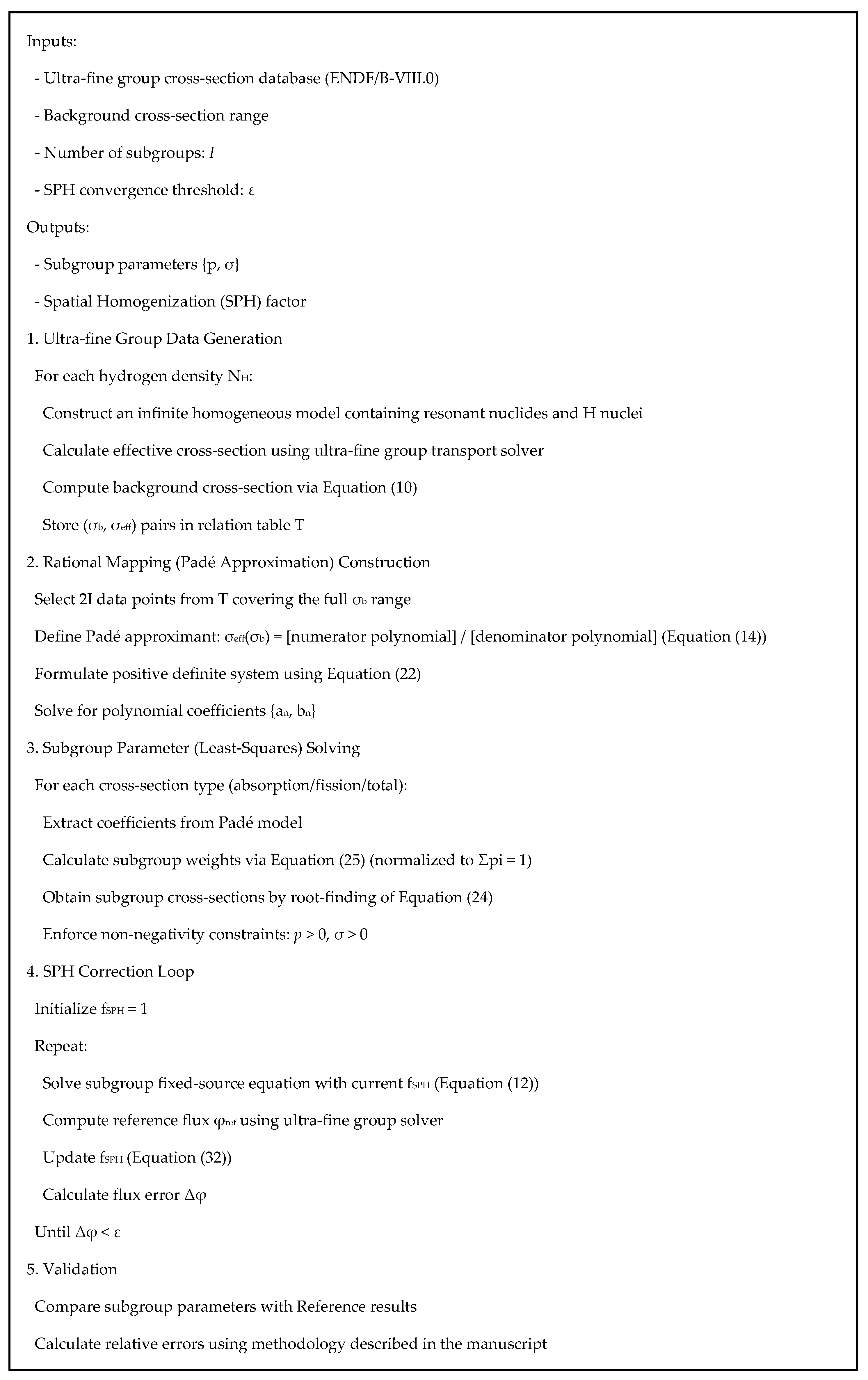
To better describe the whole process,
Figure 3 displays the pseudocode which systematically outlines the key steps of the improved subgroup method. The pseudocode includes the input of ultra-fine group data, construction of the rational mapping via Padé approximation, least-squares solution for subgroup cross-sections, and the iterative SPH correction loop, with clear references to the corresponding equations in the text.
3. Numerical Analysis of Approximation Accuracy
This paper adopts the 47-group structure provided by the HELIOS-1.11 program [
30], with resonance energy groups being groups 10 to 25. The continuous energy database used for generating the resonance cross-section table is ENDF/B-VIII.0. The detailed 47-group energy structure is shown in
Table 1. With the specific energy boundaries of each group clearly labeled (e.g., fast neutron region: Groups 1–9, resonance-concentrated region: Groups 10–25, and thermal region: Groups 26–47), we can clearly judge the applicability of each method in different energy ranges.
The reference solution for the calculation problems in this paper is obtained from the OpenMC program [
41]. As a typical representative of the Monte Carlo method, OpenMC is the “gold standard” in reactor physics calculations. It solves the neutron transport equation stochastically and can restore physical processes with nearly exact representation in the form of continuous energy and complex geometry. This high-fidelity characterization of physical essence makes it an ideal reference for verifying various approximate assumptions of deterministic methods. Therefore, the Monte Carlo method is chosen as the control instead of other deterministic methods, to verify the credibility of verification results and the advantages of the proposed method [
42,
43,
44].
3.1. Accuracy and Convergence Analysis of Parameter Fitting
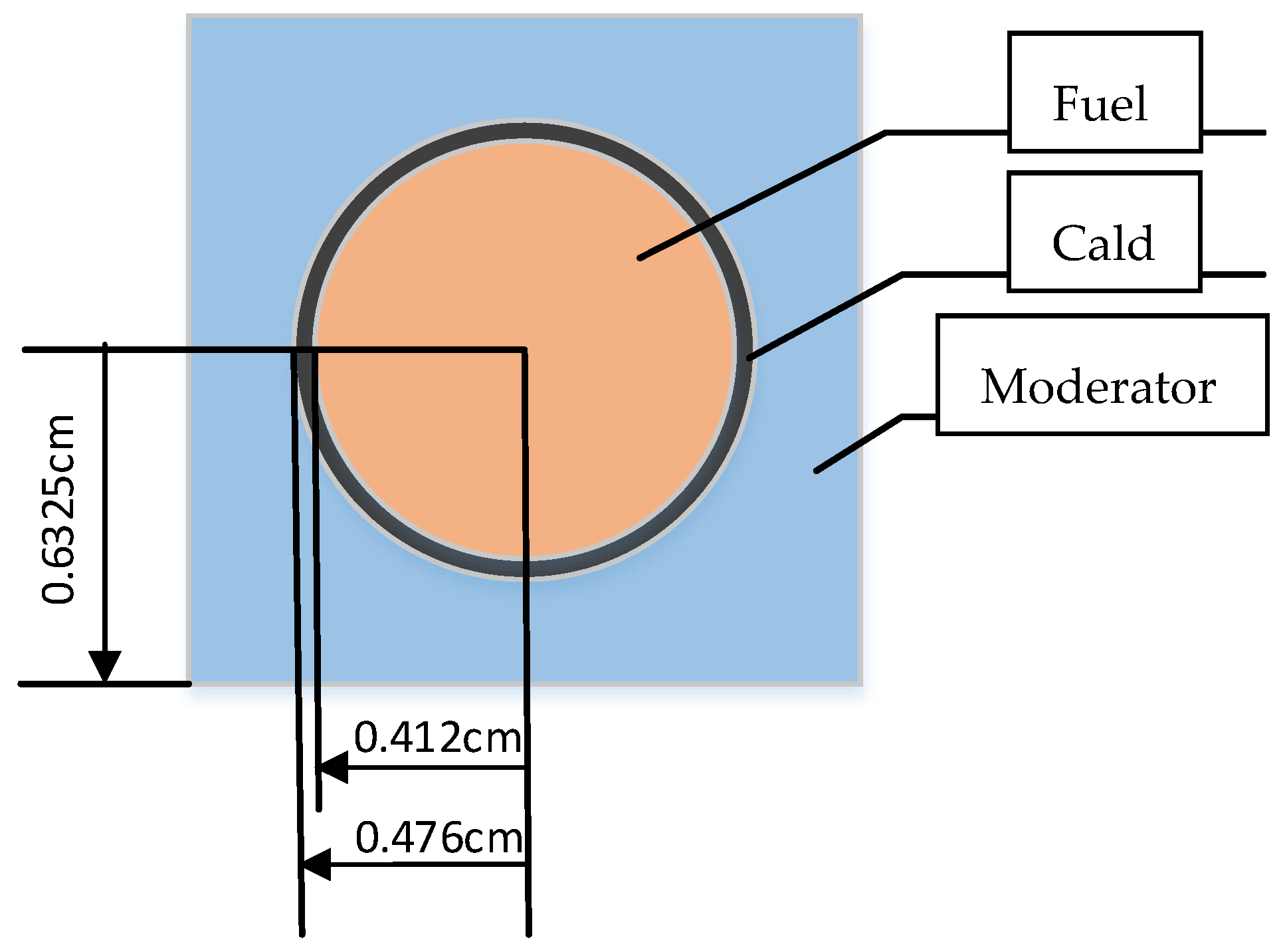
In the process of generating subgroup parameters, to improve the fitting accuracy, more subgroups should be selected for energy groups where the resonance cross-section changes drastically; for energy groups with insignificant resonance phenomena, where the cross-section varies slowly with energy, fewer subgroups are sufficient to meet the calculation requirements. Taking UO
2 fuel as an example, its geometric dimensions and fuel composition are shown in
Figure 4 and
Table 2 [
45]. The resonance phenomenon in the 19th energy group of UO
2 fuel is relatively significant, while that in the 22nd resonance group is weak. Taking these two groups as examples, the generation process and results of subgroup parameters are analyzed.
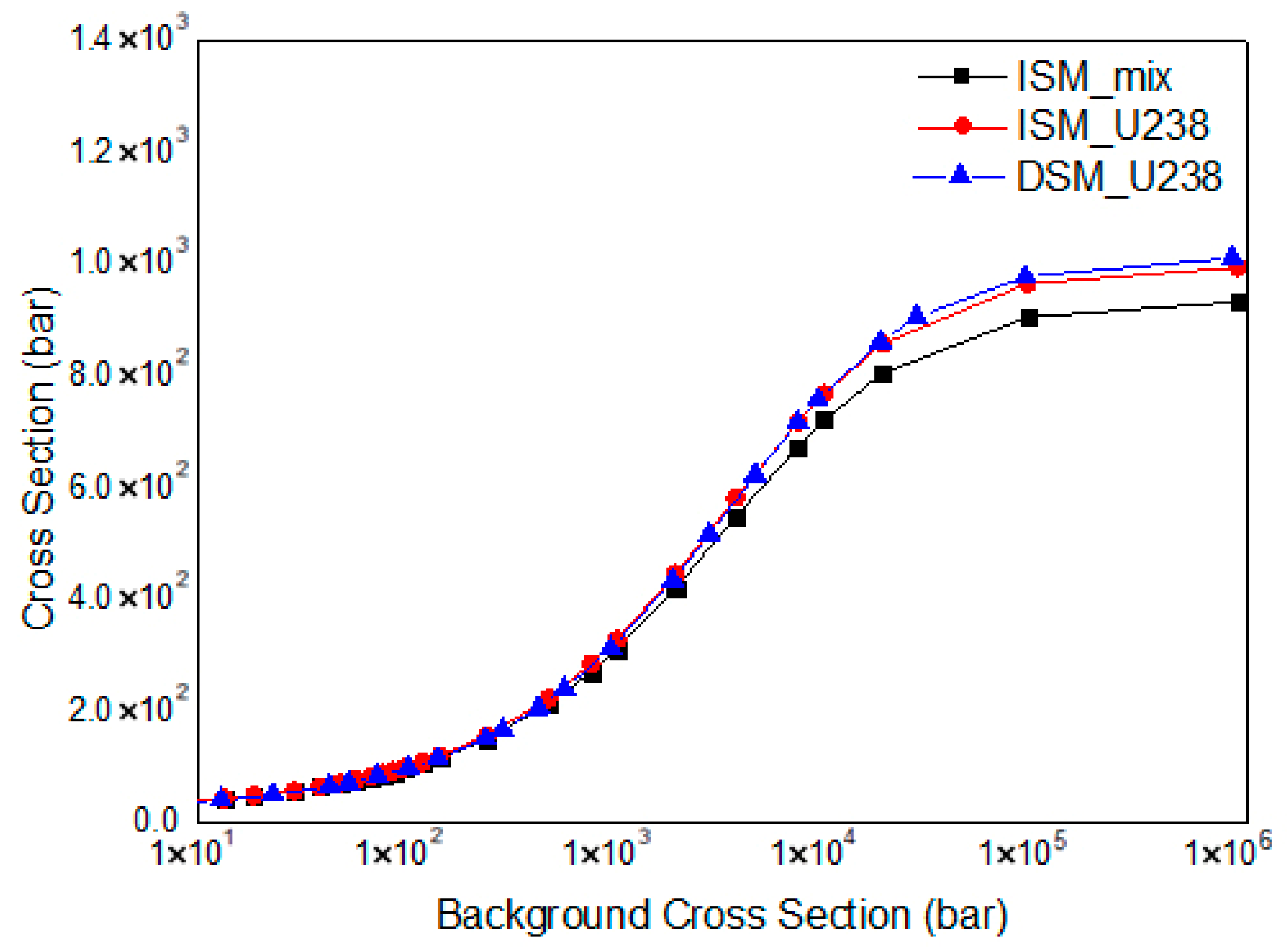
Figure 5 shows the variation law of the
238U absorption cross-section with the background cross-section in the current fuel background cross-section table. Among them, DSM refers to the absorption cross-section of
238U, a single nuclide, in the traditional subgroup parameter generation method; ISM refers to the
238U absorption cross-section considering resonance interference and the fuel-equivalent absorption cross-section in the method used in this paper. It can be seen that ISM takes the resonance interference effect into account during the generation of the background cross-section table, and the subgroup parameters generated based on this table are consistent with the actual situation of multiple resonant nuclides in the fuel. In the two resonance cross-section tables, the absorption cross-section of
238U changes with the background cross-section in the same trend. Therefore, according to this cross-section table, the subgroup parameters of each nuclide in the fuel considering resonance interference can be solved using the same numerical method as that for calculating traditional subgroup parameters in
Section 2.1.
In the 19th energy group, due to the large overall variation range, a larger number of subgroups should be selected; here five subgroups are chosen. As can be seen from
Section 2.3, nine groups of background cross-section points are needed to establish the equation system at this time. It can be seen from
Figure 5 that the variation range is larger when the background cross-section is small, and the value tends to be stable when the background cross-section is greater than 10
5 barn. In addition, in UO
2 fuel rods, the variation range of the fuel-equivalent background cross-section is generally between 10 and 100. Therefore, when establishing the equation system, under the premise of covering the overall variation trend, more points with small background cross-sections should be selected. Thus, the background cross-sections selected in this calculation process are 20, 40, 50, 70, 90, 150, 1000, 4000, and 20,000 (unit: 10
24 atom/cm
3) in sequence. The calculation results of some subgroup parameters of the fuel and its constituent nuclides are shown in
Table 3, where
and
indicate for the subgroup absorption and total cross-section of the mixture, respectively,
and
are for the subgroup absorption and total cross-section of
238U, respectively;
and
are for the subgroup absorption and total cross-section of
235U, respectively.
After calculating the subgroup parameters, the fuel-equivalent cross-sections and the cross-sections of each nuclide under different background cross-sections can be calculated according to Equations (14) and (26). Meanwhile, using the ultra-fine group program, an infinite homogeneous problem where the resonant nuclides contained in UO
2 fuel are mixed with nuclei is constructed. By adjusting the nucleus density, the fuel-equivalent background cross-section is calculated the same as that used in the calculation with Equations (14) and (26). The cross-sections of the fuel and each nuclide are calculated to verify the fitting accuracy of the subgroup parameters, and a comparison is made with the accuracy of the subgroup parameters fitted by the traditional method (DSM). The calculation results are shown in
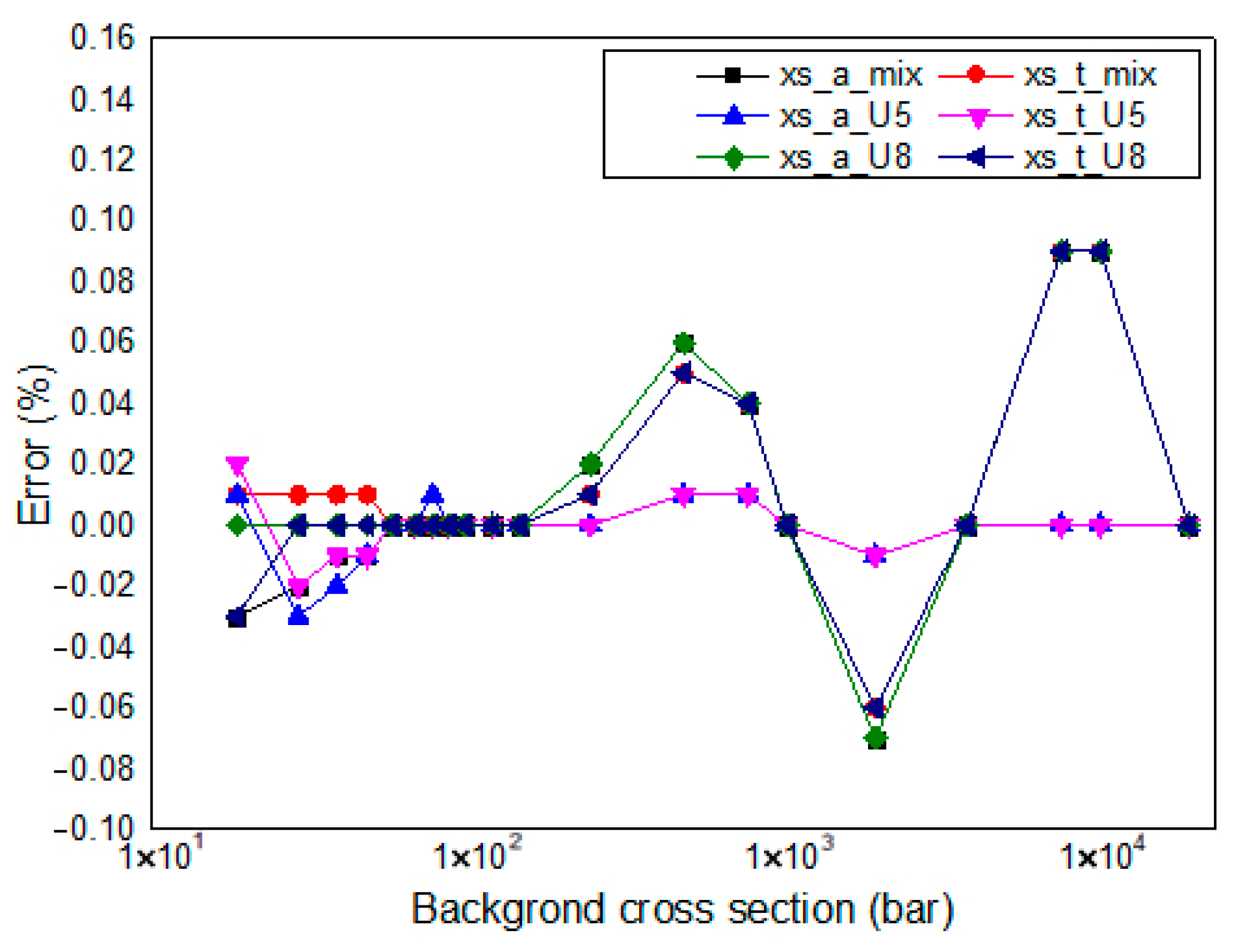
Figure 6, where the relative error (RE) is calculated by Equation (34), with all error plots annotated accordingly to ensure transparency in accuracy evaluations.
It can be seen from
Figure 6 that in the 19th energy group, the relative error between the cross-sections of each type calculated using the subgroup parameters under different background cross-sections and those directly calculated by the ultra-fine group program is small, with the maximum error within 0.1%. Among them, the error of
238U is relatively higher under a higher background cross-section. This is because
238U has a significant resonance peak in the 19th energy group, and its cross-section increases sharply with the increase in the background cross-section, resulting in a larger error at the higher resonance peak.
In this work,
235U and
238U share the same set of subgroup weights in 19th group, which is different from conventional method. To analyze the influence of the identical subgroup weights, the independent subgroup weights are also calculated for this problem. However, since the independent subgroup parameters are no longer suitable for the equations introduced in
Section 2.3, the accuracy of the reproduction of the resonance integrals by different set of subgroup parameters is compared in this part. Therefore, the subgroup parameters of 238U is calculated by conventional subgroup method again in this part, and the results are shown in
Table 4. To analyze the influence of subgroup number,
Table 4 displays two sets of subgroup parameters at the same time.
Similar with
Figure 6, the precision of independent subgroup parameters of
238U are verified and the results are shown in
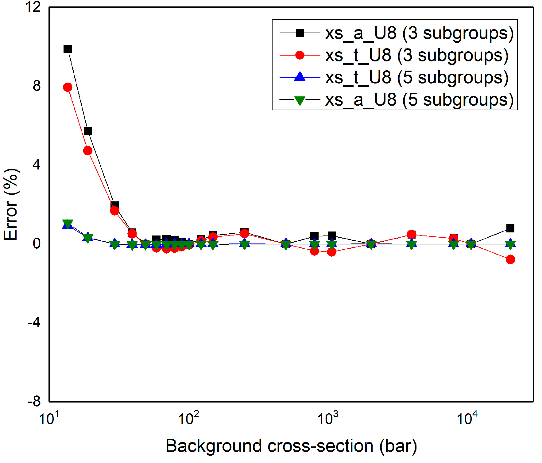
Figure 7. It could be seen that for the same subgroup numbers, the independent subgroup parameters have similar accuracy compared with subgroup parameters with identical subgroup weights. This is because the fitting process of both types of subgroup parameters all obey the rules required for the accuracy of reproducing the resonance integrals. However, for subgroup parameters with different subgroup numbers, dramatic errors could be found. For the 19th group, the resonance peak of
238U is sharp and variation in the effective cross-section along with the background cross-section changes greatly. For this condition, it is suggested to have a larger subgroup number, and it is obvious that the accuracy of subgroup parameters with five subgroups is much higher than that of three subgroups. Therefore, the calculating process proposed in this work maintains the accuracy of the conventional method with independent subgroup parameters and is suitable to handle the resonance interference condition.
The error of 235U is relatively higher under a lower background cross-section. The reason is that the resonance phenomenon of 235U in the 19th energy group is not significant, and its cross-section varies in a small range with the change in the background cross-section, so a smaller number of subgroups should be adopted. In the method of this paper, the number of subgroups for the fuel and each of its constituent nuclides in a specific energy group are the same. Since the resonance phenomenon of 238U has a more significant impact on the calculation results, the selection of the number of subgroups should focus on the fitting accuracy of the 238U cross-section, which thus has a certain impact on the fitting accuracy of 235U.
The energy range of the 22nd energy group is 4.45 eV to 5.04 eV. Within this energy range, the resonance effects of both
238U and
235U are insignificant, so the variation range of the fuel-equivalent cross-section with the background cross-section is small, as shown in
Figure 8.
In the 22nd energy group, the overall variation range is small, so a smaller number of subgroups should be selected; here, two subgroups are chosen. It can be known from
Section 2.3 that three groups of background cross-section points are needed to establish the equation system at this time. As can be seen from
Figure 8, the variation range is larger when the background cross-section is small, and the value tends to be stable when the background cross-section is greater than 10
3 barn. Since only three groups of background cross-section points are selected, and the selected points should be sufficient to describe the variation trend of the curve, the background cross-sections selected in the calculation process are 15, 150, and 20,000 (unit: 10
24 atom/cm
3) in sequence. The calculation results of some subgroup parameters of the fuel and its constituent nuclides are shown as
Table 5.
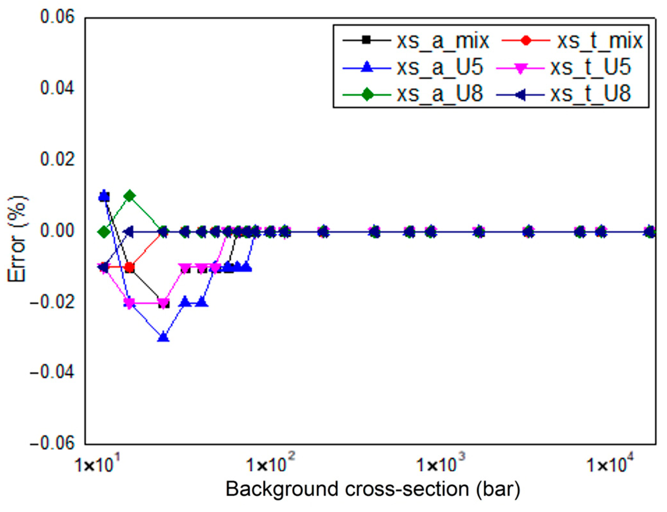
After obtaining the subgroup parameters, the fuel-equivalent cross-sections and the cross-sections of each nuclide under different background cross-sections can be calculated according to Equations (8) and (15). Meanwhile, using the ultra-fine group program, an infinite homogeneous problem where the resonant nuclides contained in UO
2 fuel are mixed with nuclei is constructed. By adjusting the nucleus density, the fuel-equivalent background cross-section is calculated the same as that used in the calculation with Equations (8) and (15). The cross-sections of the fuel and each nuclide are calculated to verify the fitting accuracy of the subgroup parameters. The fitting results of some subgroup parameters in the 22nd energy group are shown in
Figure 9.
It can be seen from
Figure 9 that in the 22nd energy group, the relative error between the cross-sections of each type calculated using the subgroup parameters under different background cross-sections and those directly calculated by the ultra-fine group program is small, with the maximum error within 0.03%. Among them, the errors of each nuclide are mainly distributed in the range of background cross-sections from 10 to 100. It can be seen from
Figure 8 that the cross-section of the 22nd energy group varies greatly in this interval, thus affecting the fitting accuracy. For higher background cross-section points, due to the rapid reduction in the variation range of each nuclide’s cross-section, the fitting accuracy is significantly improved.
For other resonance groups, subgroup parameters are generated in accordance with the above steps. In the generation process, the following principles are followed: the more significant the resonance effect in an energy group, the more subgroups are selected. However, an excessive number of subgroups will lead to numerical calculation instability, resulting in complex subgroup parameters. Therefore, this paper limits the maximum number of subgroups to five, and the number of subgroups will be selected within the range of two to five. While meeting the fitting accuracy of subgroup parameters, all items of the subgroup parameters should be positive.
3.2. Computational Benchmarks for Multi-Nuclide Resonance Systems
In this section, the UO2 and MOX cases are selected for numerical analysis. As the standard reactor fuel, UO2 features the key resonance phenomenon of interference between the fertile absorber 238U and the fissile nuclide 235U, which is the most fundamental and typical scenario of multi-resonant nuclide interaction in reactor neutronics and a critical carrier for verifying the basic effectiveness of the method; MOX fuel, however, contains multiple plutonium isotopes such as 239Pu, 240Pu, and 241Pu, and its resonance peaks not only overlap among the isotopes themselves but also intersect with those of 238U, forming a more complex resonance environment. This complexity can just test the robustness of the method in highly challenging scenarios. Based on this, we have carried out special verification cases for UO2 and MOX fuel, and by comparing the calculation errors of the fission cross-section and absorption cross-section of different resonance isotopes between traditional methods and the proposed method, we further prove the advantages of the proposed method in handling complex resonance interference of multiple isotopes.
3.2.1. Binary Resonance System: UO2 Case
The cell dimensions and material information of the UO
2 problem are shown in
Figure 3 and
Table 2. The subgroup parameters generated by the traditional method and the improved subgroup method are used for calculation, respectively. For the resonance interference effect, the traditional subgroup method provides the results calculated directly using subgroup parameters (DSM), as well as the results corrected by the iterative method (BIM, or Bondarenko iteration method) and the interference factor method (RIFM, or resonance interference factor method). These results are compared with the effective resonance self-shielding cross-sections of each nuclide in the fuel region calculated by the improved subgroup method (ISM, or improved subgroup method) introduced in this paper. The transport calculation module uniformly uses the method of characteristics for calculation [
46]. The calculation results of UO
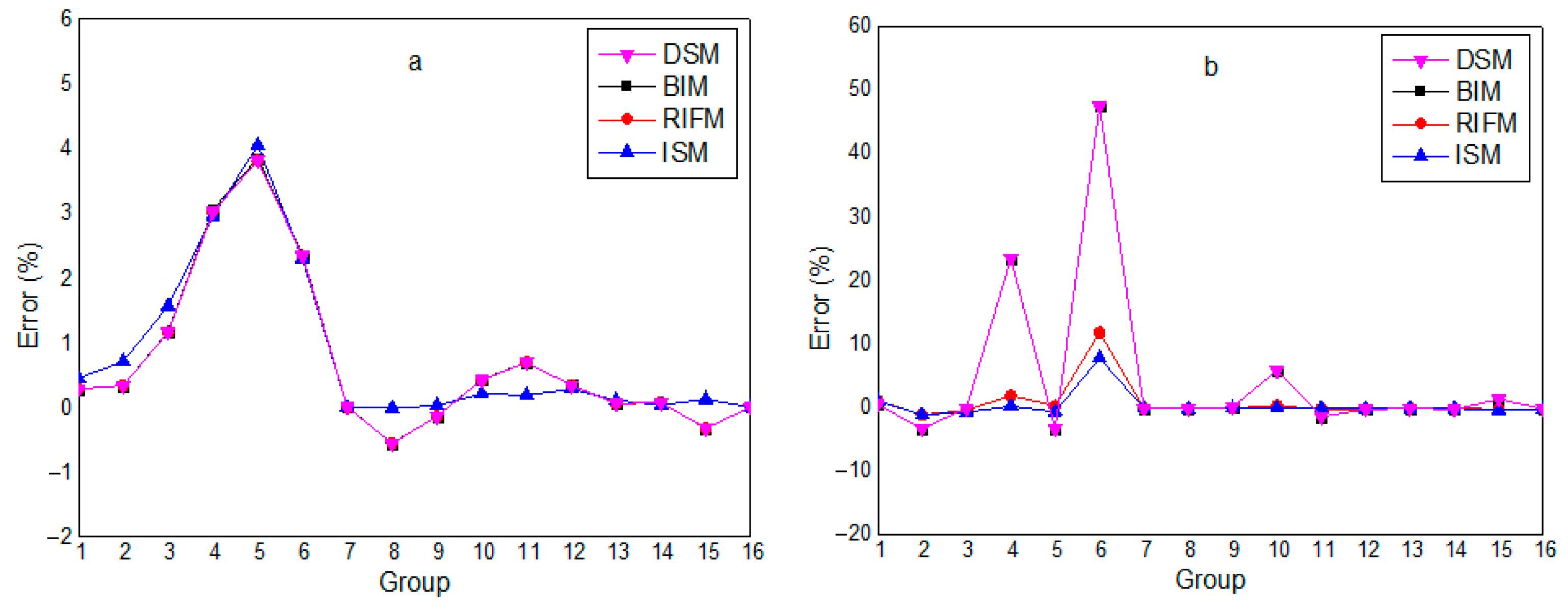
2 fuel cross-sections are shown in
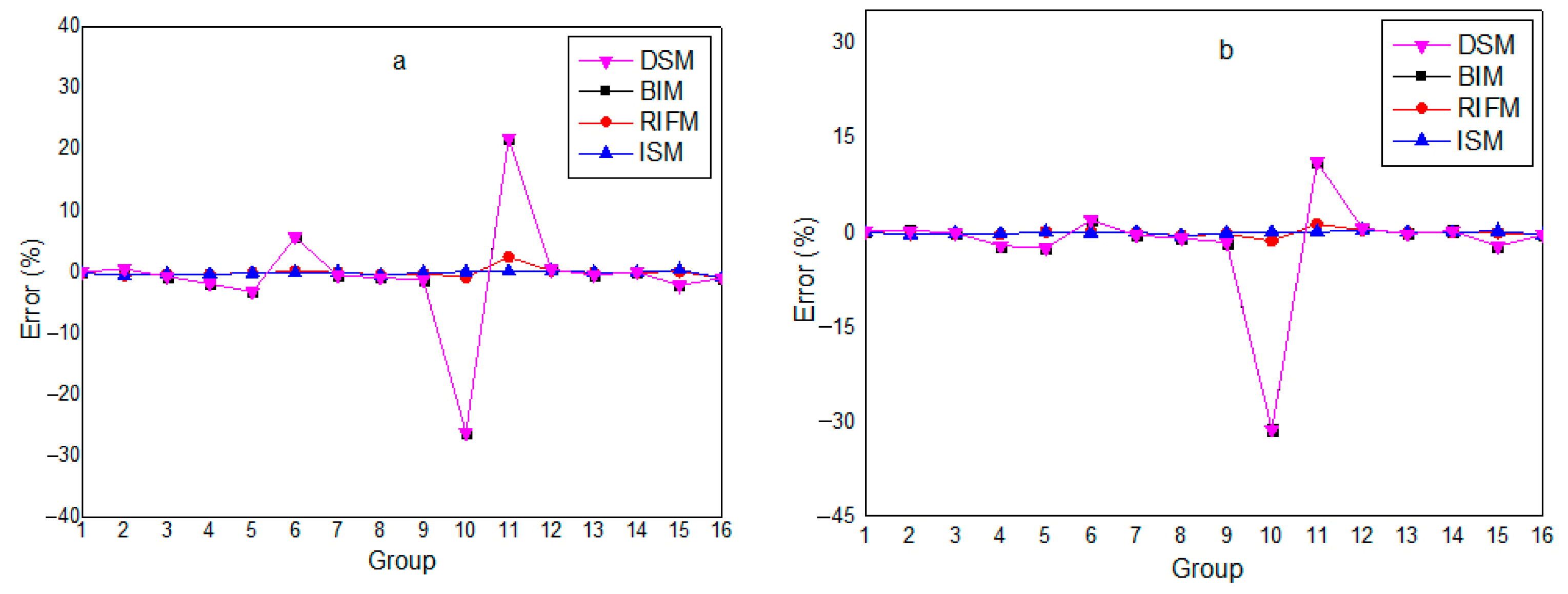
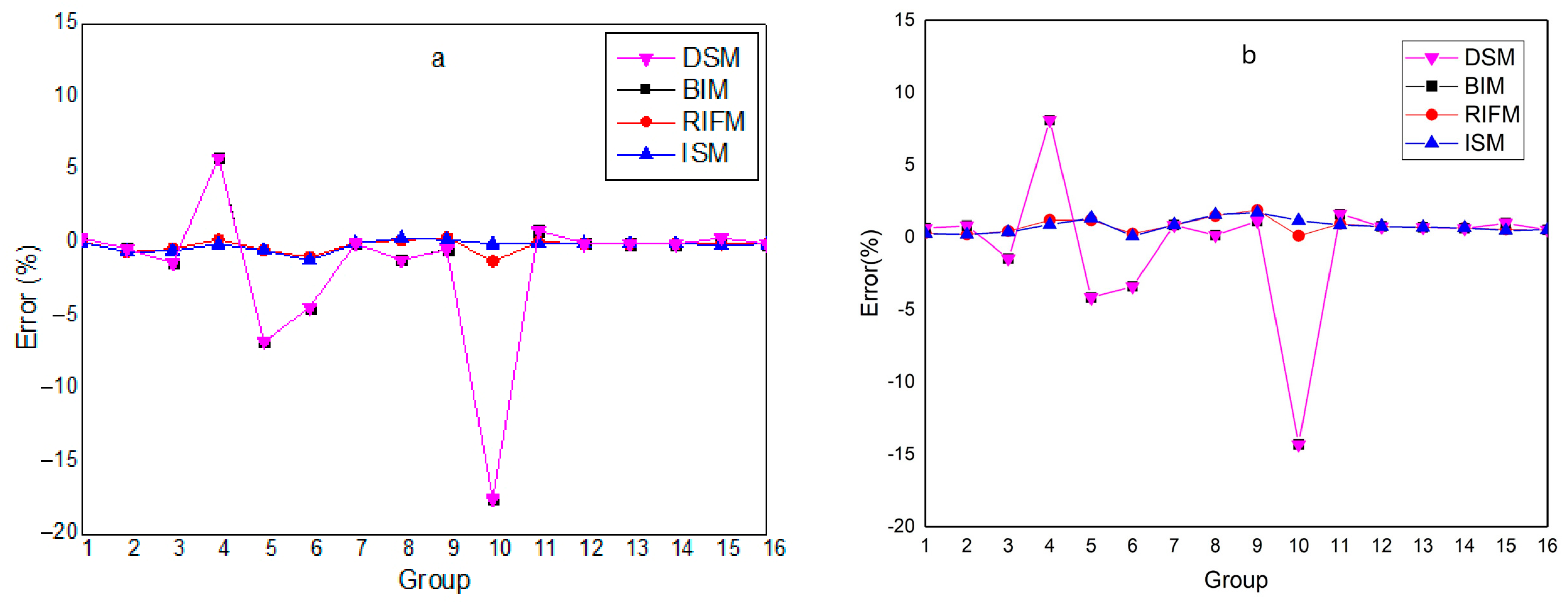
Figure 10 and
Figure 11.
Compared with directly using traditional subgroup parameters (DSM), the improved subgroup method (ISM) has higher overall accuracy in calculating the cross-sections of the two resonant nuclides in the fuel. For
238U, the calculation error of DSM is not large. After correction using BIM, the error basically remains unchanged, and the two curves almost overlap; after correction using RIFM, the cross-section errors in some energy groups are significantly reduced. The calculation error of using ISM subgroup parameters is similar to the error range after RIFM correction. For
235U, the calculation error of DSM is extremely large, which can no longer meet the calculation requirements. After correcting DSM with BIM, the error of the absorption cross-section does not change significantly, and the error of the fission cross-section is significantly reduced, but the maximum error still exceeds −10%, which does not meet the calculation requirements. This is because the resonance interference phenomenon is mainly caused by the
238U nuclide affecting other resonant nuclides, and neither DSM nor BIM can accurately handle the resonance interference effect, so the calculation accuracy of DSM and BIM for other resonant nuclides is low. After correcting DSM with RIFM, the errors of the absorption and fission cross-sections of
235U are significantly reduced. Since there are only two resonant nuclides at this time, the cost of generating interference factors is low. Compared with the above three calculation results, the cross-section calculation error of ISM is the smallest overall.
Table 6 presents the k
∞ errors of UO
2 fuel pin cells calculated using different resonance treatment methods, with OpenMC results as the benchmark. The error is shown by pcm and is calculated by (Calculated value—OpenMC reference value) × 10
5, where 1 pcm = 10
−5. DSM yields an error of −708 pcm, which is reduced to −608 pcm after BIM correction. RIFM further narrows the error to −253 pcm. ISM optimizes the error to −228 pcm through multi-nuclide equivalent cross-section mapping, and when combined with the SPH factor, the error is minimized to only 5 pcm, approaching the benchmark value. In reactor design, safety margins are usually measured in hundreds of pcm, and an error of −708 pcm is far beyond the engineering acceptable range. If core design is based on this method, it will directly cause core parameters such as criticality and power distribution to deviate from safety standards, thereby triggering the risk of design failure. In sharp contrast, the ISM + SPH method significantly reduces this error to 5 pcm, which is the most physically meaningful achievement of this paper. It not only verifies the key role of the SPH factor in reaction rate conservation but also ensures the reliability of the method in the calculation of core reactor parameters. Overall, the numerical results validate the method’s accurate capture of resonance interference effects and the effectiveness of the SPH factor in maintaining reaction rate conservation.
Moreover, the proposed method in this study achieves high computational efficiency by preprocessing resonance interference effects during the construction of the subgroup parameter database. This means that no additional processing of resonance interference is required during actual engineering calculations, significantly reducing runtime in practical applications.
To quantify the computational performance, all calculations in this study were performed using an AMD Ryzen 7 4800H processor (2.90 GHz, LENOVO, Beijing, China). For a single pin-cell UO
2 problem, the total time required for subgroup resonance calculations is less than 1 s. This efficiency makes the method well suited for integration into reactor design codes, as it maintains high precision while meeting the computational speed requirements of engineering practice. For DSM and BIM, since DSM also does not have any treatment for resonance interference effect, the time consumption would be less than RIFM, but with much worse accuracy. BIM and RIFM would have greater times for repeated calculations. ISM + SPH have slightly more time than BIM, but the accuracy has been improved noticeably. Overall, ISM + SPH compromise regarding time and accuracy. The detailed CPU time consumed by subgroup resonance calculation for the UO
2 Case is shown in
Table 7.
3.2.2. High-Dimensional Coupling System: MOX Case
The lattice dimensions and material information of the MOX problem are shown in
Figure 3 and
Table 8. The subgroup parameters generated by the traditional method and the improved subgroup method are used for calculation, respectively. For the resonance interference effect, the traditional subgroup method provides the results calculated directly using subgroup parameters (DSM), as well as the results corrected by the iterative method (BIM) and the interference factor method (RIFM). These results are compared with the effective resonance self-shielding cross-sections of each nuclide in the fuel region calculated by the improved subgroup method (ISM) introduced in this paper. The transport calculation module uniformly uses the method of characteristics for calculation. The calculation results of MOX fuel cross-sections are shown in
Figure 12,
Figure 13 and
Figure 14.
Compared with the direct calculation using traditional subgroup parameters (DSM), the improved subgroup method (ISM) has higher overall accuracy in calculating the cross-sections of each resonant nuclide in MOX fuel. For 238U, DSM has small errors in high-energy groups and large errors in low-energy groups. After correction with BIM, the error basically remains unchanged, and the two curves almost overlap; after correction with RIFM, the error is relatively reduced in high-energy groups but tends to increase in low-energy groups. The calculation error of using ISM subgroup parameters is similar to that after RIFM correction, and the two curves almost overlap, showing better accuracy than DSM and BIM.
For
235U,
239Pu, and
240Pu, the calculation errors of DSM are extremely large, which can no longer meet the calculation requirements. After correcting DSM with BIM, the errors of absorption and fission cross-sections do not change significantly, and there is no correction effect on resonance interference, which does not meet the calculation requirements. After correction with RIFM, the cross-section errors of
235U,
239Pu, and
240Pu are all reduced to a large extent, but there are still high errors in some energy groups. The calculation results of ISM are the best. Compared with the above results of DSM, BIM correction, and RIFM correction, ISM has the smallest calculation errors for each nuclide’s cross-sections. The calculation accuracy of ISM combined with the SPH method is the highest.
Table 9 shows that the errors of DSM and BIM are −269 pcm and −271 pcm, respectively, reflecting the complexity of multi-nuclide resonance interference. ISM controls the error at −212 pcm, and when combined with the SPH factor, the error shifts to 45 pcm. Although slightly higher than the UO
2 Case due to Pu isotope coupling effects, it still outperforms traditional methods significantly. This demonstrates that the method maintains computational stability in high-dimensional resonance systems and meets the engineering accuracy requirements for complex fuel design.
To analyze the contribution of SPH correction, an ablation table and corresponding analysis comparing ISM with and without SPH on benchmark fuel systems is shown in
Table 10. For UO
2 fuel, the k
∞ error reduces from −228 pcm (ISM without SPH) to +5 pcm (ISM + SPH), with 97.9% of the total error reduction attributed to SPH; for MOX fuel with
239Pu, the error decreases from −212 pcm to +45 pcm, where SPH accounts for 79.7% of the improvement. This confirms that while the Padé-based subgroup method handles resonance interference (contributing ~20–25% error reduction), SPH specifically corrects spatial flux mismatch. The results demonstrate that SPH is indispensable for achieving reaction rate conservation in heterogeneous systems.
3.2.3. Depletion Case with Rim Effect Along the Radial Direction
To further validate the capability of the proposed method in capturing spatial self-shielding effects and its robustness under burnup conditions (where isotopic composition changes dynamically), a JAEA single-cell burnup MOX problem was selected. The geometric dimensions of this problem are consistent with those in
Figure 3. In this calculation, the fuel rod was divided into 10 annular sub-regions with equal volume centered at the fuel rod’s center. The nuclide composition and nucleon density of each sub-region are detailed in
Table 11. The BIM, RIFM, and the ISM introduced in this paper were, respectively, used to calculate the effective resonance self-shielding cross-sections of each nuclide in each fuel region. Due to the edge effect, nuclear reactions are mainly concentrated in the periphery of the fuel rod, significantly affecting the spatial distribution of cross-sections along the radial direction of the fuel rod.
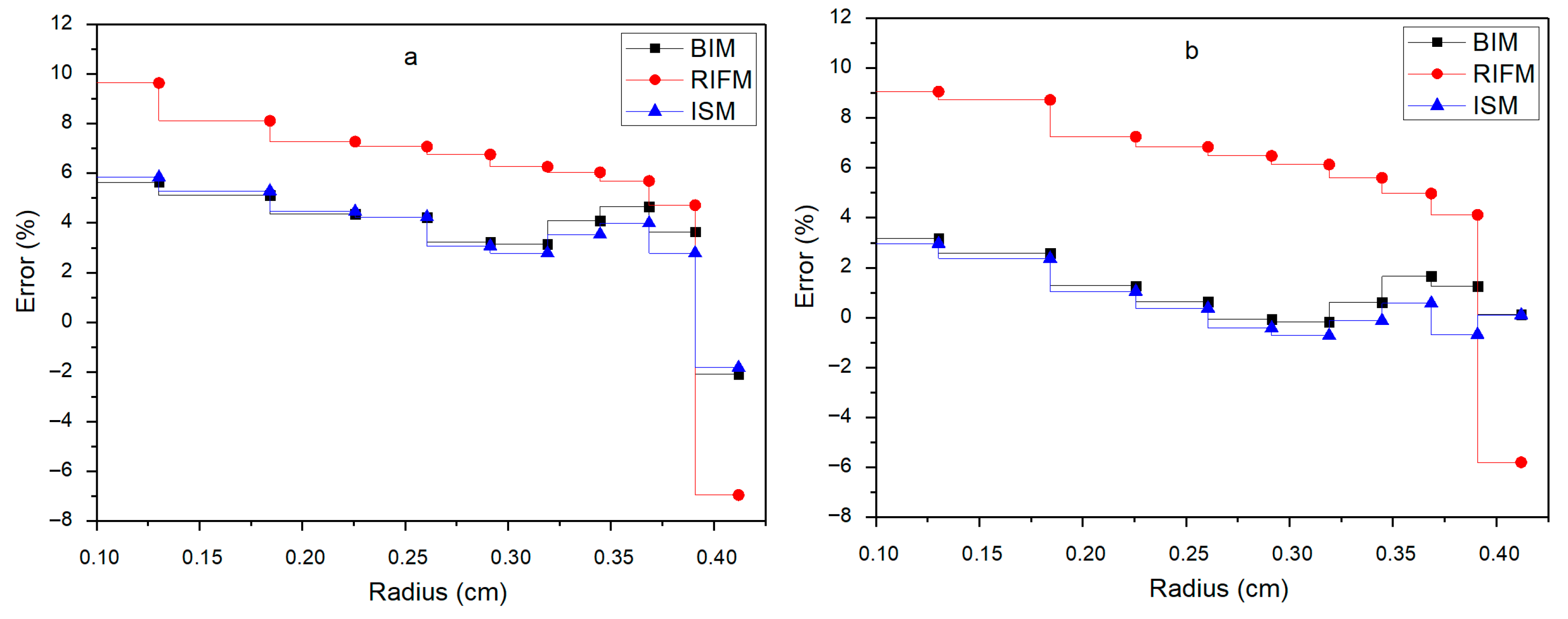
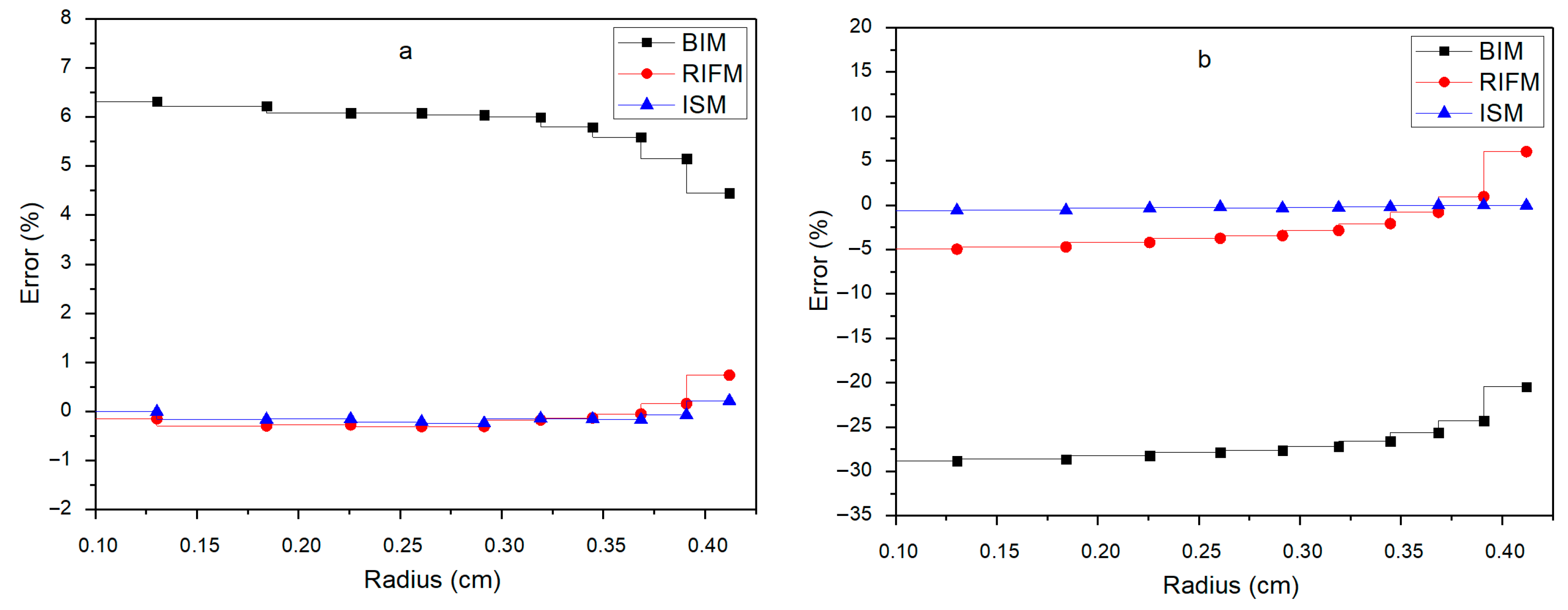
Figure 15 and
Figure 16 illustrate the spatial distribution of relative errors of absorption cross-sections for the key nuclides
238U and
235U in the 15th and 19th energy groups along the radial direction of the fuel rod. For
238U in the 15th and 19th energy groups, the BIM shows relatively large errors, with the error at the outer radius reaching about 10% and 9%, respectively. The RIFM reduces the error to approximately 6% and 5% at the same positions, while the ISM further controls the error within about 6% and 0%, respectively, and the error shows a decreasing trend with the increase in radius. For
235U in the 15th and 19th energy groups, the BIM has significant errors, with the error in the 19th energy group even reaching about—30%. The RIFM improves the accuracy, with errors of about—1% and—8%, respectively, and the ISM achieves the best accuracy, with errors nearly around 0% in both energy groups. Compared with BIM and RIFM, the ISM has smaller errors in the radial distribution of fuel cross-sections. In the 15th and 19th energy groups of
238U, due to the high energy range and dense resonance peaks in these groups, the results of the BIM are relatively accurate compared to the RIFM, and the overall accuracy of ISM is better than that of BIM and RIFM. The error of ISM in the inner region comes from the inherent error of subgroup parameters, which also exists in the case of single-resonance nuclides. Therefore, the applicability of subgroup parameters in the inner region of the fuel rod needs to be improved. Among the results of
235U, the calculation accuracy of ISM is the best. Since the cross-section of
235U is strongly interfered with by
238U, the calculation error of BIM is large; compared with
238U, the calculation accuracy of RIFM for
235U is improved.
The reference solution for keff in this problem is 1.12813. The resonance self-shielding cross-sections obtained by the above three methods were used in a unified characteristic line transport solver to calculate k∞ and compared with the benchmark solution of the Monte Carlo program. The calculation deviations of BIM, RIFM, ISM, and ISM + SPH are 509 pcm, −383 pcm, −217 pcm, and −84 pcm, respectively, indicating that the calculation method proposed in this paper has high calculation accuracy. Moreover, this problem involves the dynamic change in isotopic composition during burnup (239Pu accumulates and 235U is consumed). Even though the subgroup parameters are generated for the initial composition, the ISM still maintains good accuracy, and the ISM + SPH method further improves the accuracy, meeting the strict requirements of nuclear safety analysis for high precision.
To comprehensively measure the physical performance, we also verified the calculation deviation of reaction rates. The formula for calculating the relative error of the absorption reaction rate is shown as Equation (35):
In Equation (35), cal represents the calculated value, ref represents the referenced value, x is the reaction type, r is the resonance nuclide number, k is the flat source region number, g is the energy group number, σ is the effective resonance cross-section, ϕ is the effective scalar flux, N is the nucleon number density, V is the area of the flat source region, G is the total number of energy groups, and K is the number of flat source regions in the fuel rod.
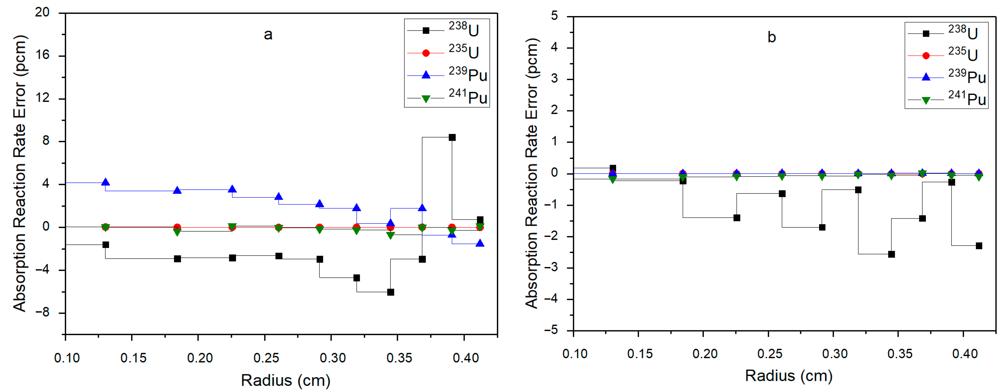
The radial distribution of the absorption reaction rate deviation for each nuclide in the 15th and 19th energy groups is shown in
Figure 17. For the 15th energy group, both
238U and
239Pu have strong resonance peaks, and the cross-sections of these two nuclides show an obvious increasing trend along the radial direction. The maximum radial deviations of
238U and
239Pu in this energy segment are 8 pcm and 4 pcm, respectively, while the deviations of
235U and
241Pu are within ±1 pcm, indicating high calculation accuracy. For the 19th energy group,
238U has a very significant resonance peak in this range, thus producing a strong spatial self-shielding effect. It can be seen from
Figure 17 that the absorption cross-section of
238U gradually increases outward along the fuel rod, especially in the outermost region. The improved subgroup method can accurately describe this phenomenon, and the maximum deviation of the radial absorption reaction rate of
238U is −3 pcm. The resonance phenomenon of
235U,
239Pu, and
241Pu in this energy segment is not obvious, and only
241Pu has a small-amplitude cross-section change along the radial direction. Therefore, the absorption reaction rate deviations of these three nuclides in this energy group are very small, basically within ±0.5 pcm.
3.2.4. Comparison of Different Temperatures, Boron Concentrations and Moderator Densities
To verify the calculation accuracy of the ISM under different operating conditions, this section selects the VERA core physics benchmark problems published by the Oak Ridge National Laboratory (ORNL) of the United States to carry out a multi-condition comparative analysis for typical single pin-cell problems in pressurized water reactors. During reactor operation, fluctuations in fuel temperature and moderator parameters directly affect the neutron energy spectrum and resonance self-shielding effect, thereby changing the critical characteristics of the core. Therefore, it is necessary to verify the universality of the method through differentiated working conditions. The single pin-cell series (VERA 1A~1D) in the VERA benchmark provides standardized geometric and material conditions, with a uniform fuel enrichment of 3.1 wt% and a moderator boron concentration of 1300 ppm. A verification system covering typical operating ranges is constructed by setting different fuel temperatures, moderator temperatures, and density parameters.
Specific cases cover four groups of working conditions: fuel temperature and moderator temperature are 565 K/565 K, 600 K/600 K, 900 K/600 K, and 1200 K/600 K, respectively, corresponding to different degrees of Doppler effect; boric acid solubility; and moderator density. The geometric structure, material composition, and benchmark values of each problem are provided in reference [
47]. The single pin-cell problems select the VERA 1A~1D benchmark problems for calculation verification. The fuel enrichment of this series of problems is 3.1 wt%, and the moderator boron concentration is 1300 ppm. The four problems have different fuel temperatures, moderator temperatures, and densities, so the method in this work can be verified for single pin-cell problems under different working conditions. The information of each case and the effective multiplication factor deviation calculated for the selected VERA single pin-cells are shown in
Table 12. The maximum deviation of
k∞ calculation for the four cases is −103 pcm, indicating high calculation accuracy.
To further demonstrate the ability of the ISM + SPH method proposed in this study to accurately characterize spectra and reaction kinetics in resonance self-shielding calculations,
Figure 18 and
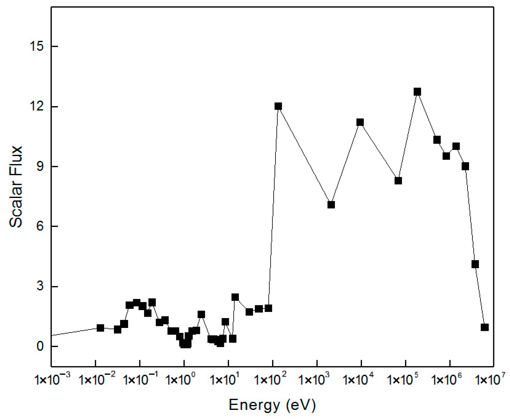
Figure 19 present the calculated neutron flux spectrum and macroscopic reaction rate of the fuel region for the VERA 1A case, respectively.
Figure 18 shows the neutron flux spectrum of the fuel region for the VERA 1A case, covering an energy range from 10
−3 eV to 10
7 eV. In the thermal neutron region (10
−3 eV–1 eV), the flux decreases slowly with increasing energy, and the ISM + SPH method accurately captures the energy distribution law of thermal neutrons. In the resonance energy range (1–10 keV), the flux shows alternating “fluctuation-plateau” characteristics, corresponding to resonance peaks. At the resonance peak positions of nuclides like
235U and
238U (e.g., the 19th energy group at 7.34 eV and the 22nd energy group at 4.45–5.04 eV), the flux presents local valleys due to resonance absorption. The depth of these valleys matches well with resonance intensity. This demonstrates the method’s accurate simulation of flux distortion caused by resonance self-shielding. In the fast neutron region (>10 keV), the flux decays rapidly with increasing energy, and the spectrum shape is smooth, indicating the method’s good stability in calculating neutron transport in non-resonance regions. The overall spectrum fully reproduces the neutron distribution law across all energy segments, verifying the method’s ability to accurately capture resonance physics processes.
Figure 19 shows the macroscopic reaction rates (including fission and absorption reactions) in the fuel region for the VERA 1A case. The fission reaction rate curve exhibits a “peak clustering” characteristic in the resonance energy range. At the energy positions corresponding to the fission resonance peaks of
235U and
239Pu, the reaction rate rises significantly, and the peak intensity is consistent with the fission cross-section characteristics of the nuclides. In the thermal neutron region (10
−3 eV–1 eV), the fission reaction rate remains at a high level, which conforms to the physical law that thermal neutrons easily induce fission. The absorption reaction rate curve shows strong peaks. These peaks are in the energy range dominated by
238U resonance capture. One example is the 19th energy group at 7.34 eV. The peak positions correspond exactly to the valley positions in the flux spectrum. This is consistent with the physical nature of resonance self-shielding. This figure demonstrates the method’s ability to accurately calculate the kinetic characteristics of different nuclear reactions and confirms its effective handling of resonance interference effects.
4. Theoretical Implications and Computational Advancements
This study has established a rigorous mathematical framework for addressing the longstanding challenge of resonance interference in multi-nuclide systems through the novel integration of Padé rational approximation theory with subgroup methodology. The core theoretical advancement lies in the development of a covariant formalism that preserves coupling information between resonant nuclides via equivalent cross-section mapping, effectively transforming the high-dimensional approximation problem into a mathematically tractable rational function representation. This method constructs an infinite homogeneous model of multiple resonant nuclides consistent with the actual fuel composition, uses an ultra-fine group program to calculate effective resonance cross-sections under different background cross-sections and creates a corresponding relationship table, solves subgroup parameters by combining Padé approximation and numerical methods, integrating the handling of resonance interference effects into the process of generating subgroup parameters, while introducing the SPH super-homogenization factor to ensure reaction rate conservation. Numerical validation results show that, for both UO2 and MOX fuels, the improved method (ISM) significantly outperforms the traditional subgroup method (DSM) and its modified versions (BIM, RIFM) in calculating effective resonance self-shielded cross-sections, with smaller calculation errors for the cross-sections of nuclides such as 238U, 235U, 239Pu, and 240Pu. Moreover, when combined with the SPH method, the calculation error of k∞ can be controlled within an extremely small range, effectively improving the accuracy and reliability in reactor physics calculations when considering resonance interference effects. Overall, this mathematical architecture provides a paradigm for coupled nonlinear systems beyond reactor physics, particularly where spectral covariance must be preserved. Future extensions will address spatial self-shielding through integrated transport-rational formulations.
However, the current model’s treatment of geometry remains simplified, focusing primarily on the idealized scenario of “pin-cell,” and has not directly incorporated the effect of neutron leakage in finite systems. This is because the current research prioritizes verifying the core algorithm accuracy of resonance self-shielding for multi-resonant nuclides; in the future, it will be further extended to practical finite core scenarios by coupling neutron leakage correction factors. Second, we have emphasized that the improvement of the Padé rational approximation method proposed in this paper is not merely a theoretical optimization, but directly translates into an enhanced ability to model the physics of neutron transport in highly challenging systems by more accurately capturing resonance interference effects, the model can make more reliable and safer predictions of key reactor behaviors
Furthermore, the Padé rational function framework in this study has expansion potential: it can be coupled with the solution process of neutron transport equations to calculate spatial self-shielding effect, thereby providing high-precision calculation methods for burnup effects, rim effects, etc. Meanwhile, this method also demonstrates good applicability to other reactor types, such as heavy water reactors, graphite reactors, fast reactors, high-temperature gas-cooled reactors, etc. Follow-up studies can further carry out verification calculations for different reactor types. In the future, exploring the combination with deep learning can also be pursued to enhance the parameter identification efficiency of high-dimensional systems.
