Abstract
A high-precision coal seam model is crucial to improving the adaptability of unmanned mining technology to geological conditions. However, the accuracy of a coal seam model constructed with boreholes and geophysical data is far from the required accuracy of unmanned mining (sub-decimeter level). Therefore, it is necessary to collect geological data revealed by mining and to update the coal seam model dynamically. As a solution to this problem, this paper proposes a new method for conducting off-site geological surveying of longwall faces by integrating multi-source monitoring data. The spatial attitudes of hydraulic supports are monitored to estimate the local dip angles of longwall face. A roof line calculation model was established, which integrates the local inclination angle of the longwall face, the number of hydraulic supports, and the roof elevation of the two roadways. Meanwhile, the local coal–rock columns at the camera observation point are extracted automatically using image segmentation and a proportional relationship between the picture and the actual scene. Coal and rock walls and a support guarding plate in the longwall face image are identified accurately using the coal-rock support segmentation model trained with U-net. Then, the height of the coal (or rock) wall above the coal–rock interface is estimated automatically according to the image segmentation and the similar proportion equation of actual longwall face and longwall face image. Combined with mining height information, the local coal–rock column can be extracted. Finally, the geological surveying profile of longwall face can be obtained by integrating the estimated roof line and local coal–rock columns. The field test demonstrated the efficacy of the method. This study helps to address a long-standing limitation of insufficient geological adaptability of intelligent mining technology.
Keywords:
coal seam model update; geological survey; multi-data fusion; longwall face image segmentation; intelligent coal mining MSC:
00A71
1. Introduction
Geological surveying of longwall face is essential in underground coal mine geology. A geological technician can analyze the formation occurrence of coal seams (thickness, roof or floor level, and geological structure) in the area to be mined on the basis of longwall face profiles [1,2,3]. With accurate geological surveying, geological forecasting has enhanced the safety level and production efficiency of coal mines [4,5]. For instance, advanced geological exploration in a coal mine in Inner Mongolia, China, issues warnings for a reverse fault 30 days in advance, which buys crucial time for adjusting the cutting parameters of the shearer and avoids equipment damage and production halts [6]. The significance of the geological profile extends beyond safety management. As the most reliable input for coal seam modeling, it fundamentally guarantees the reliable operation of an intelligent mining system. High-precision 3D models of coal seams can optimize three key parameters in real time: the drum height and advancement sequence of the coal shearer, and the inclination angle of the scraper conveyor. Field tests show that model-oriented dynamic adjustments can increase the coal recovery rate by 3–5% and reduce rock cutting by 18–22% simultaneously [7]. The longwall face profile is the most reliable data type for constructing an accurate coal seam model. Meanwhile, a high-precision coal seam model can guide the dynamic adjustment of the mining height and advancing direction of the shearer, thereby enhancing the adaptability of intelligent mining technology to geological conditions. Currently, efficient and accurate geological measurement of longwall working faces is a research hotspot in the coal mining industry [8].
Traditionally, the surveying of longwall face mainly relies on manual mapping with an optical level. This method requires technicians to measure the elevation point-by-point along the longwall face and simultaneously record various geological elements, including lithological changes, structural features, and stratigraphic contact relationships [9]. Due to the complex and harsh working environment of longwall face, manual surveying is often of low frequency and the data reliability is not strong. Therefore, lots of researchers have carried out a series of intelligent perception studies on the geological information of longwall face. The following paper discusses the current research status in terms of intelligent perception of spatial information and image recognition of coal and rock information on the longwall face.
Currently, there are mainly three intelligent perception methods for longwall face space information. The first one is to utilize high-precision pose sensors installed on fully mechanized coal mine mining equipment to sense the slope and height of the longwall face. Liu et al. [10] used multiple sensors to monitor the pose of the shearer in real time, calculated the three-dimensional coordinates and cutting drum trajectory, and obtained the top and bottom plate curves of the longwall face. The JOY Company collected relevant data on the longwall face by integrating various pose sensors on the fully mechanized mining equipment. And the bottom line of the longwall face was calculated by fusing the elevations of the two roadways and monitoring data. The LASC research team in Australia integrated multi-source sensor data, including inertial navigation and coal and rock detectors, to construct a dynamic cutting model to guide shearer operations [11,12,13,14]. The second method is to use three-dimensional LiDAR to scan the spatial contour of the longwall face. Jiang et al. [15] proposed a point cloud slicing technique and a feature point extraction algorithm based on 3D LiDAR point cloud data, which automatically extracts the coal cutting roof line. Wang et al. [16] utilized a mobile 3D laser scanning system to quickly reconstruct the 3D scene of the roadway and longwall face. CSIRO of Australia developed an explosion-proof laser radar, which can efficiently scan the contour of the longwall face and the fully mechanized mining equipment [17,18]. The third method is to perceive the undulating shape of the coal seam from the geological marker layer. Jonathon and Andrew [19] used a thermal infrared camera installed on the shearer to automatically track geological marker zones closely related to the horizontal orientation of coal seams. The geological marker layers in infrared images were extracted by using the line segment detection algorithm and the Kalman filtering algorithm, and the coal seam dip angle was determined by the geological marker layers. Wang et al. [20] found that the lithological indicators of coal seams exhibit different optical characteristics due to differences in composition and structure, and explored their potential application in the intelligent mining of coal and rock identification. Zhu et al. [21] proposed an iterative modeling method based on drilling constraints along coal seams. This method effectively solves the problem of insufficient accuracy caused by sparse drilling in traditional modeling.
The intelligent perception of coal and rock information is generally achieved through the recognition of the longwall face. Wu et al. [22] proposed various coal and rock image recognition methods, including local constraint self-learning, Curvelet transform and compressive sensing, and dictionary learning. Sun and Chen [23] used an asymmetric generalized Gaussian model in the wavelet domain to characterize the texture features of coal and rock images. Si et al. [24] proposed a coal and rock image recognition method based on an improved U-net network model, which improves recognition accuracy and efficiency. Zhang et al. [25] improved the accuracy of coal and rock infrared image recognition by actively stimulating the coal and rock walls in the longwall face and using a temperature gradient model to divide the isotherms of the infrared image. Wu et al. [26] proposed a coal and rock interface recognition method based on a boundary tracking algorithm and artificial neural network. Gao et al. [27] constructed a coal and rock segmentation tower network using tower pooling architecture and convolutional neural networks to enhance the global information representation of feature maps. Yang et al. [28] conducted a study on hyperspectral identification of coal and rock interfaces by utilizing the differences in the mineral content of Al-OH vibration structures in coal and rock layers. Wei et al. [29] also created hyperspectral identification methods for coal and rock walls in the Huainan mining area of China.
In summary, the current research on geological information perception in mining sites generally suffers from the lack of synchronous perception of spatial morphology and coal rock attributes. Traditional coal rock identification techniques struggle to support dynamic geological model updates. Therefore, an off-site geological survey method for long-wall working faces that integrates a longwall face image and the pose perception data of the hydraulic support is proposed. Firstly, multiple cameras installed on the hydraulic support collect longwall face images, and the tilt angle detection sensors collect the tilt angle of the hydraulic support. Then, the convolutional neural network (CNN) is adopted to extract the distribution information of coal and rock, and the local coal and rock columns are obtained by fusing the mining height. Then, a top line calculation model is constructed by integrating data such as the measurements of the roadways on both sides, the inclination angle, and the position of the hydraulic supports. Finally, profiles of the longwall face are generated based on the roof line and the local coal–rock columns. This method greatly improves the surveying efficiency of longwall faces.
2. Demand for High-Precision Coal Seam Model
Since the end of the 12th Five-Year Plan, China has developed a memory cutting intelligent mining technology in a longwall panel with simple geological conditions [30]. The technical bottleneck in the real-time identification of coal–rock interface has restricted the application of the memory intelligent cutting system in longwall panels with complex geological condition. Therefore, domestic scholars have successively put forward academic concepts such as precise coal mining [31], transparent mining [32], and autonomous navigation cutting [33]. The core ideas involve exploring longwall panel geological conditions, establishing high-precision coal seam geological models, then digitally simulating mining operations to plan shearer cutting trajectories, and ultimately achieving autonomous coal mining through the coordinated control of fully mechanized mining machinery. The static coal seam geological model constructed using pre-mining geologic survey data such as well logging [34] and in-seam survey [35] has an overall accuracy at the meter-level due to the limitations of geological exploration resolution and exploration grid. However, the accuracy is still of centimeter-level accuracy when using collaborative control with comprehensive mining machinery. This precision gap has been identified as the critical bottleneck in autonomous mining systems [36].
Chinese scholars have proposed a dynamic geological modeling framework to deal with the challenge of high-precision longwall panel modeling. That is, the geological information of the longwall face is dynamically surveyed, and the static longwall panel geological model is modified accordingly during the mining process, ensuring the accuracy of the geological model of the area to be mined meets the requirements of autonomous planning and mining (Figure 1). The practices of cascade construction for a geological model of a longwall panel for autonomous planning coal mining based on manual surveying have been implemented in mines such as Yangquan Xinyuan Coal Mine and Huang ling Coal Mine. By dynamically updating the geological model of the longwall face using the geological information revealed during mining, the modeling error of roof, floor, and thickness of ab un-mined coal seam within 8–15 m in front of the longwall face is less than 30 cm, which basically meets the accuracy requirements of autonomous planning coal mining. The prediction error of the top and bottom plates and thickness changes in the coal seam within the range of 8 to 15 m in front of the working face is less than 30 cm [37]. In addition, the LASC (Longwall Automation Steering Committee) research team of the Australian CSIRO uses multiple sensors to perceive geological information revealed during mining and updates the cutting model for unmanned coal mining [38]. Therefore, intelligent geological information surveying of longwall panels is a key breakthrough in high-precision geological modeling, which is of great significance for the development of autonomous planning coal mining.
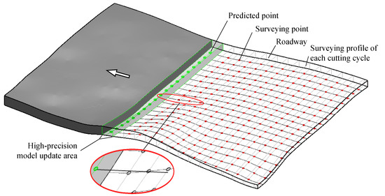
Figure 1.
Dynamic modification of the geological model of the longwall panel using the geological information revealed during mining.
3. Geological Surveying Method of Longwall Face Profile
3.1. Geological Surveying Principle
3.1.1. Layout of Hydraulic Supports on the Longwall Face
As is shown in Figure 2, hydraulic supports are arranged in the longwall face to support the roof and maintain the safety of the working space. The hydraulic support is one of the most important pieces of equipment in the longwall face. The other main equipment includes the shearer, scraper conveyor, etc. To achieve unmanned operation in the longwall face, one high-definition camera is installed for every 4 to 6 hydraulic supports to monitor the working conditions of the longwall face in real time, replacing personnel inspection. In addition, the hydraulic support is also integrated with a variety of other sensors, including a height sensor for monitoring the mining height and an inclinometer for monitoring the spatial attitude of the hydraulic support. The key point of this paper lies in how to utilize the multi-source monitoring data obtained from these sensors to acquire the geological information of the longwall face.
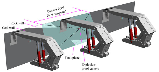
Figure 2.
Layout of hydraulic supports on the longwall face.
3.1.2. Geological Surveying Principle of Longwall Face
Figure 3 shows the geological surveying principle of the longwall face. The geological surveying of the longwall face consists of three parts: the calculation of the top and bottom plate lines of the longwall face, the extraction coal–rock columnar, and geological surveying. (1) Calculation of the top and bottom plate lines of the longwall face. The local slopes αi (1≤ ≤ n) of the longwall face can be estimated according to the spatial posture of the hydraulic supports. The slope lengths li (1≤ ≤ n) are calculated by the distance from each support to the roadway. The bottom plate line of the longwall face is calculated by taking the elevation of the bottom plates on both sides of the roadways and high-precision geological data such as drilling and logging as hard constraints. Based on the bottom plate line, the top plate line of the longwall face can be obtained by integrating the mining height data recorded by the hydraulic support and the top plate elevations of the two side roadways. (2) Range of coal and rock walls. The image intelligent segmentation algorithm is adopted to automatically identify the distribution of coal and rock wall in the longwall face image. The coal–rock columnar at the video observation point can be constructed by combination with the geological exploration information of the longwall face, markers (such as hydraulic support face guard), mining height, and other information. (3) Fusion of the longwall face geological profile. The longwall face geological profile is generated by integrating the top and bottom plate lines and the coal–rock columns at each observation point. The updated geological profile can serve as the key dynamic data for the update of the longwall face geological model.
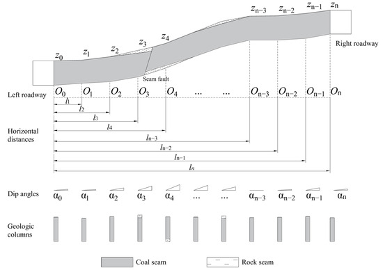
Figure 3.
Geological surveying principle of longwall face.
3.2. Roof Line Calculation Model
It is necessary to set some assumptions and simplify the actual problem for the purpose of estimating the roof line of longwall face. Therefore, the following three assumptions are made:
- The undulating shape of the longwall face changes continuously and gently, without abrupt change;
- All of the longwall face images are taken under the condition that the cameras are level and the optical axes is vertical to the longwall face;
- The longwall face is photographed with a certain horizontal spacer.
A simplified roof line calculating model, as shown in Figure 3, was constructed on the basis of the above assumptions. The relevant variables are defined as follows:
The roof heights at (n + 1) observation points are as follows:
The local dip angles at (n + 1) observation points are as follows:
When longwall face extends upward, set the dip angle to positive; otherwise, set the dip angle to negative.
The horizontal distances from (n + 1) observation points to the left roadway wall are as follows:
= 0 and = n in Equations (1)–(3) denote the left and right roadway observation points, respectively. = 1, 2, …, n − 1 denote the ordinal camera observation points from left to right in the longwall face. The dip angles αi ( = 1, 2, …, n − 1) are determined according to the spatial posture of the hydraulic supports. The horizontal distances li ( = 1, 2, …, n − 1) are determined through the serial number of the corresponding supports.
Thus, the following variables are known:
The following variables are unknown:
The dip angle of the longwall face is generally small and changes gently. Meanwhile, one camera is mounted for every 2~6 supports in the intelligent longwall face. The horizontal distance of adjacent observation points is less than 9 m (li − li−1 < 9 m) given that the supporting space of a support is general about 1.5 m. Therefore, the red broken line in Figure 3 can be used to approximate the roof line of the longwall face (green line in Figure 3).
The quantitative relationship of the roof heights at adjacent observation points can be given by the following:
The definition of variable, , is shown as Equation (7),
Equation (4) applied to Equation (7) leads to Equation (8):
Due to the simplification of the problem and the residuals of li and αi, Equation (8) is not valid. Therefore, Equation (8) can be modified to contain the residual ε.
ε can be averaged into ( = 1, 2, …, n) based on the surveying adjustment theory:
where ( = 1, …, n) is the error component adjusted to . The mathematical solution of is derived as follows
Equations (8) and (9) applied to Equation (6) leads to the following equation of zi ( = 1, …, n − 1):
The variable zi, li ( = 1, …, n − 1) determines the approximate roof line of the longwall face.
3.3. Local Coal–Rock Columnar Surveying
3.3.1. Coal–Rock Column Calculation Model
Figure 4 shows the imaging principle of the camera. When the optical axis of the camera is perpendicular to the longwall face, the image and the real scene of the longwall face satisfy Equation (13).
where , represent, respectively, the actual and image heights of rock or coal wall located above the coal–rock interface; a, b are the actual and image breadths of the support guarding plate; m is the magnification of the camera.

Figure 4.
Image-forming principle of the longwall face.
For the specific longwall face, the breadth of the support guarding plate is constant. In addition, the image breadth b of the support guarding plate can be determined automatically according to image segmentation. That is, magnification m is a known quantity. The bottom boundary of the longwall face is generally unclear due to accumulated loose coal. However, the distance h0 from the bottom of the support guarding plate to the longwall face roof is known for a specific support, as shown in Figure 5. Therefore, Hr can be represented as Equation (14).
where ∆h is the height difference between the coal–rock interface and the bottom of support guarding plate. ∆h can be calculated using Equation (15).
where and are the average Y-coordinates of the coal–rock interface and the bottom line of the support guarding plate in the longwall face image, which can be obtained automatically with image segmentation. When the coal–rock interface locates above the bottom of the support guarding plate, ∆h < 0; otherwise, ∆h > 0.
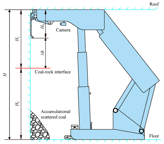
Figure 5.
Roof support dimension.
The height Hf of the rock or coal wall located below the coal–rock interface can be calculated using Equation (16).
where H is the mining height monitored by hydraulic pillars of the roof support or the clinometer mounted in shearer cutting drums.
Finally, the local coal–rock columns at the camera observation points can be determined according to Hr and Hf.
3.3.2. Coal–Rock–Support Image Segmentation Model
- Training data preparation
A total of 892 original coal wall images and 181 original rock wall images were collected as a basic experimental dataset. Typical coal and rock wall images are shown in Figure 6a and b, respectively. Coal walls are characterized by sporadic reflective surfaces and inky black color. Meanwhile, rock walls are off-white.

Figure 6.
Typical coal wall (a) and rock wall (b) images. (The area selected by the purple circle is the rock interface).
Data augmentation methods are used to expand the image training set. The selected data augmentation method should be in line with the actual situation. Otherwise, new data not only fail to improve the robustness of the training model but may also lead to the model not converging. Due to the lack of features such as up and down flipping, and complex noise in the longwall face image, data augmentation methods such as up and down flipping, adding noise, and filling are not applicable. Therefore, a data augmentation scheme suitable for the semantic segmentation of longwall face images has been proposed by integrating geometric transformations and multi-sample data augmentation methods (Figure 7).
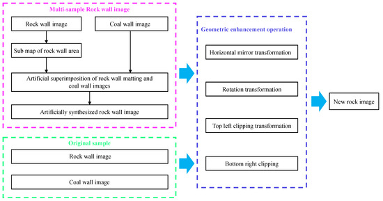
Figure 7.
Data augmentation scheme for longwall face.
Multi-sample rock wall data enhancement. Considering the scarcity of basic rock wall data, a multi-sample data enhancement method was adopted to artificially synthesize a large number of rock wall images. There are three steps in the specific process, as follows. Step 1: Using image editing software to extract the rock wall areas from the basic rock wall image. A typical rock wall area sub-graph is shown in Figure 8a. Step 2: For high-quality coal wall images (such as Figure 8b), selecting a suitable area (such as the coal wall area between adjacent guard plates) and removing the image (as shown in Figure 8c). Step 3: Selecting the sub image of the rock wall area and moving it to the bottom of the coal wall image where a portion of the area has been removed, generating a new rock wall image (as shown in Figure 8d). It should be noted that the transition at the coal–rock interface is natural and the stratum direction is nearly horizontal in the artificial rock wall image.
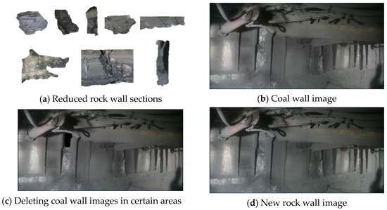
Figure 8.
Coal-rock Wall Area Images.
Geometry and color enhancement. The original coal wall images, rock wall images, and multi-sample enhanced rock wall images constitute a new basic training image set. Horizontal mirroring, central rotation, top-left cropping, and bottom-right cropping operations on each image in the new image set were, respectively, performed to increase the size of the training set by four times. A total of 3370 coal wall images and 3385 rock wall images were obtained through the data augmentation scheme shown in Figure 9. The masks of the longwall face images were labeled by technical personnel with rich on-site working experience using the open-source software package LabelMe (v4.5.13) [39,40]. White (RGB color value: (255, 255, 255)), gray (RGB color value: (130, 130, 130)), and black (RGB color value: (0, 0, 0)) areas in the mask images denote support guarding plate, rock wall, and coal wall, respectively. A case of longwall face image labeling is shown as Figure 9.

Figure 9.
Longwall face image (a) and the corresponding mask (b).
- 2.
- Training, validation, and testing sets
To train and evaluate the segmentation model of longwall face images, all images are randomly divided into training, validation, and testing sets. The functions of the training and testing sets are model fitting, model evaluation, and hyperparameter adjustment, respectively. The testing set is used to evaluate the generalization ability of the trained model. First of all, 50 coal wall images and 50 rock wall images are selected randomly, which comprised the testing set. The remaining coal and rock wall images are divided into training and testing sub-groups at a ratio of 9:1, as shown in Table 1.

Table 1.
Division of training, validation, and testing sets.
- 3.
- Model training strategies
The U-Net architecture has the advantages of high segmentation accuracy with only small training samples required. Therefore, a U-Net network was built to train coal–rock–support image segmentation model by using Kera’s deep learning frameworks. To obtain a better performance of coal–rock–support image segmentation, two different training strategies are designed and compared, as shown in Table 2.

Table 2.
Two kinds of model training strategies.
The learning curves of Strategy Ⅰ (Figure 10a,b) and Ⅱ (Figure 10c,d) are similar generally, such as in curvilinear trend, final IOU, and Loss. However, Strategy Ⅱ works better in terms of details, as is mainly reflected in the following two aspects:
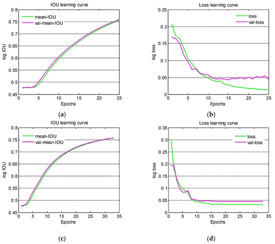
Figure 10.
Learning curves of Strategy Ⅰ (a,b) and Ⅱ (c,d).
Firstly, the loss and Val loss values of Strategy Ⅱ are stable at 0.0328 and 0.0460, respectively, after the 15th epoch. Meanwhile, the Val loss value fluctuates slightly around 0.05, and the loss value continue to decrease, indicating that the model is over-fitting.
Secondly, the IOU value of Strategy Ⅱ tends to be stable at 0.75 after the 25th epoch, with a significant decrease in the growth rate. Meanwhile, the IOU value of Strategy Ⅰ still maintains a high growth rate, showing a trend of overfitting.
Therefore, the coal–rock–support image segmentation model trained with Strategy Ⅱ was selected.
- 4.
- Model testing
Typical coal–rock–support image segmentation of the testing set is shown in Figure 11. In each sub-image, the left shows the original longwall face image, and the right shows the image segmentation. The grayscale segmentation images were converted into RGB color images for highlighting, where the blue, red, and green areas correspond to support guarding plate, coal wall, and rock wall, respectively. Both of the coal and rock wall image segmentation cases demonstrate the applicability of the trained coal–rock–support image segmentation model.
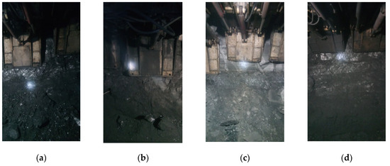
Figure 11.
Typical segmentation results of coal (a) and rock (b) wall images. Figures (c,d) show the images of the coal rock interface.
4. Field Test
4.1. Overview of the Surveyed Longwall Face
The No. 31004 Longwall Panel of Xinyuan Coal Mine was the surveying case with a geological structure. The coal seam thickness varies from 2.52 to 2.82 m, with an average of 2.72 m. The dip angle of the coal seam generally varies from 2 to 8°, with an average of 6°. There are 160 supports in the longwall face, with a width of 1.5 m per a support. One camera is mounted for every 10 supports from the No. 1 support to monitor the operation of the shearer and the roof supports. That is, the No. 1, No. 10, No. 20 …, No. 160 supports are mounted with cameras.
The surveyed longwall face was cut on 12 December 2020. The roof level, coal seam thickness, and dip angle of longwall face on the side of auxiliary intake airway were 504.82 m, 3.13 m, and 7.5°, respectively. The roof level, coal seam thickness, and dip angle of the longwall face on the side of the intake airway were 517.63 m, 2.55 m, and 0.4°, respectively. Typical longwall face images are shown in Figure 12. The whole images show that the area where the No. 65#~115# supports are located is the fault-affected area. Detailed information about the rock and coal walls in the fault-affected area is listed in Table 3.

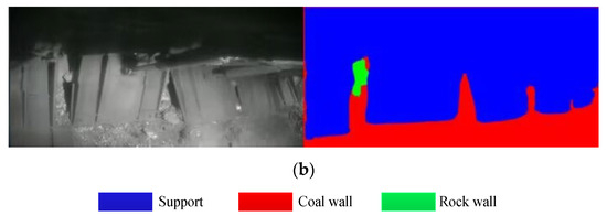
Figure 12.
Longwall face images from the No. 50# (a), 75# (b) supports.

Table 3.
Information on rocks and coal walls in the fault affected area.
4.2. Roof Line
Table 4 shows the local dip angles estimated from images and measured manually. The roof line coordinates calculated according to position monitoring and manual measuring were also illustrated. Two roof lines are calculated on the basis of the estimated and measured dip angles of longwall face, as shown in Figure 13. Compared with the measured roof line, the maximum and average absolute errors of the image-based roof line are 0.25 m and 0.12 m. Due to error accumulation, the error of the roof level gradually accumulates from the two side roadways to the middle of the longwall face.

Table 4.
Monitoring and measured dip angles.

Figure 13.
Longwall face roof lines estimated with support position monitoring and measured manually.
4.3. Coal–Rock Columns in Fault-Affected Area
Figure 14a shows the longwall face image at the No. 70# support. Here exists the footwall of a normal fault, with upper coal and lower rock. Figure 14b shows the image segmentation of Figure 14a using the trained CNN model. The blue, red, and green areas denote the support, coal wall and rock Wall, respectively. The support model of No. 31004 Longwall Panel is ZY8000/18/37D. The support dimension shows that the height difference between the guarding plate bottom and the longwall face roof is 1.25 m and the width of the guarding plate is 1.20 m. The magnification m is calculated to be 0.0045 on the basis of the actual width and image width (Figure 14b). The recorded mining height is 3.10 m. Figure 14c,d shows the coal–rock columns, which are estimated with a longwall face image and measured manually, respectively. The absolute error in the coal (rock) wall height estimated with the image is 0.08 m, and the relative errors of coal and rock wall height are 3.7% and 8.6%, respectively.
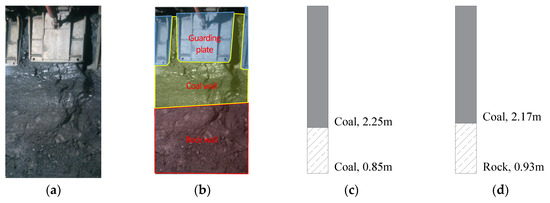
Figure 14.
Longwall face image at No. 70# support (a), the image segmentation (b), estimated coal-rock column (c), and manually measured coal–rock column (d).
Table 5 shows the detailed information of the coal–rock columns at the No. 100#, 110# supports extracted from the longwall face images. Figure 15a,b shows the extracted coal–rock columns at the No. 100# (a), 110# (b) supports, respectively.

Table 5.
Detailed information of coal and rock pillars at the No. 100#, 110# supports.
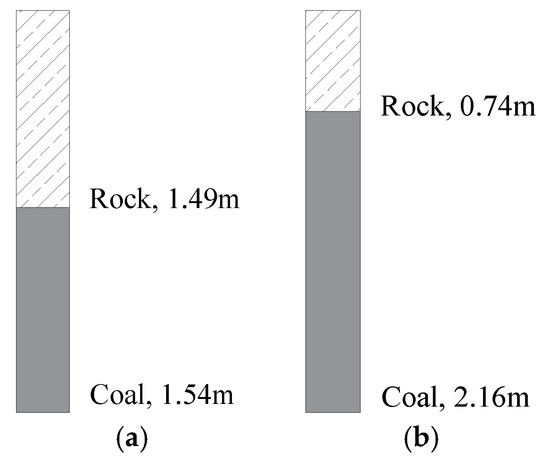
Figure 15.
Coal–rock columns at the No. 100# (a), 110# (b) supports, estimated with longwall face images.
4.4. Longwall Face Geological Profile
A longwall face geological profile can be drawn by integrating the roof line and coal–rock columns. Figure 16a,b shows the geological profiles are estimated with images and measured manually, respectively. Both the manual and image-based surveys utilize the mining height data to draw coal–rock columns. Therefore, the difference between the manual and image-based surveying profiles are mainly the roof line level and the coal/rock heights. The error analysis of the roof line and coal/rock wall heights are discussed in Section 3.2 and Section 3.3, respectively. The precision of the image-based surveying profiles mainly depends on the posture perception information of the hydraulic supports, which indicate the undulation form of the longwall face.

Figure 16.
Geology profiles based on longwall face images (a) and manual measurement (b).
4.5. Factors Influencing Geological Information Extraction
There is a lot of geological coal seam information in the longwall face images. However, there are also many negative factors that affect the identification and extraction of the geological information, mainly including the following three factors:
- Coal mining dust and spray. Dust and spray attached to the camera lens have a severe impact on imaging quality, that is, the longwall face images become blurred. On the other hand, coal walls, rock walls, and supports will become less recognizable when dust is attached to these objects, especially for the coal and rock walls. In this case, the extraction of local coal–rock columnar information may result in significant errors.
- High-precision measurement of the local roof/floor inclination angle. The field test shows that the accuracy of longwall face geological surveying mainly depends on the roof line estimated with the high-precision measurement of the local roof/floor inclination angle.
- Overlap of highlights, shearers, and workers. The geological information in the image data naturally decreases when these objects block out the longwall face.
The above discussions are useful for improving off-site geological surveying methods and indicate the applicable conditions of the proposed method. Further investigation needs to be undertaken to guarantee the stable operation of off-site geological surveying. The above discussions show that the image quality determines the accuracy of geological surveying of the longwall face. Therefore, obtaining high-quality longwall face images and high-precision local roof/floor inclination angles are the key to improving the accuracy of geological surveying. In the future, several measures can be taken to improve the image quality and efficiency of automatic surveying, including a standardized workflow, dark image enhancement, self-cleaning camera, and automatic measurement of support space attitude. Meanwhile, the development of this technology can effectively deliver accurate geological information, providing new ideas for the future development of intelligent mining technology.
5. Conclusions
- Longwall face images capture dynamic geological information, such as coal–rock distribution, seam fluctuations, and geological structures. Roof line estimation based on hydraulic support pose measurements, together with image-based coal–rock height extraction, enables the reconstruction of longwall geological profiles with reasonable accuracy. However, factors like dust, poor visibility, and interference from equipment and workers hinder the extraction of these data.
- A method to estimate the roof line based on the inclination angle of hydraulic supports, which reflect the undulating shape of the longwall face, has been developed. The derived mathematical model shows that the maximum and average errors in roof line estimation are 0.25 m and 0.12 m, respectively, compared to manual measurements.
- Automatic extraction of coal–rock columns is achieved through image segmentation and proportional relationships between the image and the actual scene. A U-net-based model accurately identifies coal, rock walls, and support guarding plates. The height of the coal or rock wall above the interface is estimated using proportional equations, while the height below the interface is calculated based on the mining height. The field test shows an absolute error of 0.08 m in height estimation.
- A geological survey map is generated by integrating the estimated roof line and local coal–rock columns, with the accuracy depending mainly on the roof line accuracy.
This study combines longwall face images and hydraulic support data to create a roof line model and a U-net coal–rock segmentation algorithm. The method enables automatic height estimation and dynamic geological profile generation, improving the efficiency of geological information measurement and facilitating real-time updates of geological models. Achieving dynamic updates of geological models is of great significance.
Although the proposed method shows encouraging performance, further improvements are required to enhance its robustness and extend its applicability. In future research, active lighting and optimized camera configurations can be introduced to reduce the adverse effects of dust, occlusion, and low-light environments, thereby improving the stability of image-based segmentation. The generated geological profiles will also be integrated with borehole and geophysical data to enable continuous updates of high-resolution coal seam models, which can provide stronger support for intelligent and adaptive mining operations. Moreover, because the shearer does not always strictly follow the natural undulation of the coal seam, future efforts will focus on recognizing geological marker layers within the seam (such as bedding planes and partings) to extract local undulation and refine seam geometry representation. Collectively, these efforts will advance the proposed workflow toward a more comprehensive and high-fidelity geological modeling framework for intelligent coal mining.
Author Contributions
Conceptualization, M.Z. and Z.L.; Data curation, R.R.; Funding acquisition, M.Z.; Methodology, X.Q.; Software, R.R. and X.Q.; Validation, M.Z. and Z.L.; Writing—original draft, M.Z. and R.R.; Writing—review and editing, M.Z., Z.L., H.Z., and S.K. All authors have read and agreed to the published version of the manuscript.
Funding
This work was financially supported by the National Natural Science Foundation of China (No. 52204175).
Data Availability Statement
The original contributions presented in this study are included in the article. Further inquiries can be directed to the corresponding author(s).
Acknowledgments
Special thanks to Shanxi Xinyuan Coal Co., Ltd. for providing the underground test conditions. Special thanks are given to the editors and anonymous reviewers for their valuable assistance, comments, and suggestions. All authors have read and agreed to the published version of the manuscript.
Conflicts of Interest
The authors declare no conflicts of interest.
References
- Álvarez-Fernández, M.I.; González-Nicieza, C.; Álvarez-Vigil, A.E.; García, G.H.; Torno, S. Numerical modelling and analysis of the influence of local variation in the thickness of a coal seam on surrounding stresses: Application to a practical case. Int. J. Coal Geol. 2009, 79, 157–166. [Google Scholar] [CrossRef]
- Li, X.; Li, P.; Zhu, H. Coal seam surface modeling and updating with multi-source data integration using Bayesian Geostatistics. Eng. Geol. 2013, 164, 208–221. [Google Scholar] [CrossRef]
- Wang, X.; Li, Y.; Chen, T.; Yan, Q.; Ma, L. Quantitative thickness prediction of tectonically deformed coal using Extreme Learning Machine and Principal Component Analysis: A case study. Comput. Geosci. 2017, 101, 38–47. [Google Scholar] [CrossRef]
- Wang, G.; Xu, Y.; Ren, H. Intelligent and ecological coal mining as well as clean utilization technology in China: Review and prospects. Int. J. Min. Sci. Technol. 2019, 29, 161–169. [Google Scholar] [CrossRef]
- Wang, J.; Huang, Z. The Recent Technological Development of Intelligent Mining in China. Engineering 2017, 3, 439–444. [Google Scholar] [CrossRef]
- Xu, F.; Nie, Z.; Sun, W.; Xiong, X. Theoretical and technological system for Highly efficient development of deep coalbed methane in the Eastern edge of Erdos Basin. J. China Coal Soc. 2024, 49, 528–544. [Google Scholar]
- Zhang, M.; Zhao, L.; Wang, Y.; Zhang, K. Construction and correction of a 3D digital twin for a complex gangue-bearing coal seam. Coal Geol. Explor. 2024, 52, 40–53. [Google Scholar]
- Wang, H.; Zhang, Q. Dynamic identification of coal-rock interface based on adaptive weight optimization and multi-sensor information fusion. Inf. Fusion 2019, 51, 114–128. [Google Scholar] [CrossRef]
- Yang, X.; Wang, R.; Wang, H.; Yang, Y. A novel method for measuring pose of hydraulic supports relative to inspection robot using LiDAR. Measurement 2020, 154, 107452. [Google Scholar] [CrossRef]
- Liu, W.; Zhang, X.; Wang, S. Modeling and dynamic correction technology of 3D coal seam model for coal-mining face. J. China Coal Soc. 2020, 45, 1973–1983. [Google Scholar]
- Einicke, G.A.; Ralston, J.C.; Hargrave, C.O.; Reid, D.C.; Hainsworth, D.W. Longwall mining automation an application of minimum-variance smoothing [Applications of Control]. IEEE Control Syst. 2008, 28, 28–37. [Google Scholar] [CrossRef]
- Ralston, J.C.; Hainsworth, D.W. Use of ground penetrating radar in underground coal mining. In Proceedings of the 8th International Conference on Ground Penetrating Radar (GPR 2000), Gold Coast, Australia, 23–26 May 2000; Volume 4084, pp. 731–736. [Google Scholar]
- Mundry, S.; Gajetzki, M.; Hoseinie, S.H. Longwall automation—Productivity and coal quality enhancement. Int. J. Min. Reclam. Environ. 2015, 29, 357–367. [Google Scholar]
- Ralston, J.C.; Strange, A.D. An Industrial Application of Ground Penetrating Radar for Coal Mining Horizon Sensing. In Proceedings of the 2015 International Symposium on Antennas and Propagation (ISAP), Hobart, Australia, 9–12 November 2015; Volume 37, pp. 1–4. [Google Scholar]
- Jiang, L.; Mao, S.; Li, M.; Liu, H.; Zhang, H. Research on extraction technology of coal wall and roof boundary based on laser point cloud. Coal Sci. Technol. 2022, 50, 286–291. [Google Scholar]
- Wang, H.; Liu, Z.; Lei, X.; Han, B.; Lu, Z. Key technologies and engineering practice of 3D laser scanning in coal mine roadways. Coal Geol. Explor. 2022, 50, 109–117. [Google Scholar]
- Ralston, J.C.; Hainsworth, D.W.; Reid, D.C. Recent advances in remote coal mining machine sensing, guidance, and teleoperation. Robotica 2001, 19, 513–526. [Google Scholar] [CrossRef]
- Ralston, J.C.; Reid, D.C.; Dunn, M.T.; Hainsworth, D.W. Longwall automation: Delivering enabling technology to achieve safer and more productive underground mining. Int. J. Min. Sci. Technol. 2015, 25, 865–876. [Google Scholar] [CrossRef]
- Ralston, J.C.; Strange, A.D. Developing selective mining capability for longwall shearers using thermal infrared-based seam tracking. Int. J. Min. Sci. Technol. 2013, 23, 47–53. [Google Scholar] [CrossRef]
- Wang, H.; Liu, S.; Ma, L.; Zhu, Y.; Shu, J.; Wang, X. Comprehensive correlation technology of coal and rock layers in mines for intelligent mining. Coal Geol. Explor. 2022, 50, 24–38. [Google Scholar]
- Yuan, L. Scientific conception of precision coal mining. J. China Coal Soc. 2017, 42, 1–7. [Google Scholar]
- Wu, Y.; Meng, X. Locality-constrained self-taught learning for coal-rock recognition. J. China Coal Soc. 2018, 43, 2639–2646. [Google Scholar]
- Sun, J.; Chen, B. A coal-rock recognition algorithm using wavelet-domain asymmetric generalized Gaussian models. J. China Coal Soc. 2015, 40, 568–575. [Google Scholar]
- Si, L.; Wang, Z.; Xiong, X.; Tang, C. Coal-rock recognition method of fully-mechanized coal mining face based on improved U-net network model. J. China Coal Soc. 2021, 46 (Suppl. S1), 578–589. [Google Scholar]
- Zhang, Q.; Sun, S.; Zhang, K.; Zhang, X.; Guo, T. Coal and rock interface identification based on active infrared excitation. J. China Coal Soc. 2020, 45, 3363–3370. [Google Scholar]
- Wu, D.; Liu, Q.; Huang, X.; Gao, F.; Ying, X. Coal-rock interface recognition method based on boundary tracking algorithm and artificial neural network. Coal Eng. 2021, 53, 140–146. [Google Scholar]
- Gao, F.; Ying, X. Coal-rock image recognition method for mining and heading face based on spatial pyramid pooling structure. J. China Coal Soc. 2021, 46, 4088–4102. [Google Scholar]
- Yang, E.; Wang, S.; Ge, S.; Zhang, H. Study on the principle of hyperspectral recognition of coal-rock interface. J. China Coal Soc. 2018, 43 (Suppl. S2), 646–653. [Google Scholar]
- Wei, R.; Xu, L.; Meng, X.; Wu, J.; Zhang, K. Coal and Rock Identification Method Based on Hyper Spectral Feature Absorption Peak. Spectrosc. Spectr. Anal. 2021, 41, 1942–1948. [Google Scholar]
- Wang, G.; Liu, F.; Meng, X.; Fan, J.; Wu, Q. Research and practice on intelligent coal mine construction (primary stage). Coal Sci. Technol. 2019, 47, 1–36. [Google Scholar]
- Wang, Z.; Bi, L.; Li, J.; Wu, Z.; Zhao, Z. Development Status and Trend of Mine Intelligent Mining Technology. Mathematics 2017, 13, 2217. [Google Scholar] [CrossRef]
- Wang, G.; Zhang, D. Innovation practice and development prospect of intelligent fully mechanized technology for coal mining. J. China Univ. Min. Technol. 2018, 47, 459–467. [Google Scholar]
- Ge, S.; Hao, X.; Tian, K. Principle and key technology of autonomous navigation cutting for deep coal seam. J. China Coal Soc. 2021, 46, 774–788. [Google Scholar]
- Zhu, M.; Cheng, J.; Qu, H.; Cui, W. Iterative refined model of coal seam in longwall panel with constraints of in-seam boreholes. J. Min. Saf. Eng. 2022, 39, 879–890. [Google Scholar]
- Cheng, S.; Yin, X.; Gao, F.; Pan, Y. Surrounding Rock Squeezing Classification in Underground Engineering Using a Hybrid Paradigm of Generative Artificial Intelligence and Deep Ensemble Learning. Mathematics 2024, 3832, 12–23. [Google Scholar] [CrossRef]
- Xiang, J.; Chen, J.; Zhang, A.; Zhao, X.; Zhuo, S.; Yang, S. Multi-Objective Ore Blending Optimization for Polymetallic Open-Pit Mines Based on Improved Matter-Element Extension Model and NSGA-II. Mathematics 2024, 13, 1843. [Google Scholar] [CrossRef]
- Cheng, J.; Liu, W.; Zhu, M.; Yu, B.; Zhang, Z. Experimental study on cascade optimization of geological models in intelligent mining transparency working face. Coal Sci. Technol. 2020, 48, 118–126. [Google Scholar]
- Jonathon, R.; David, R.; Chad, H.; David, H. Sensing for advancing mining automation capability: A review of underground automation technology development. Int. J. Min. Sci. Technol. 2014, 24, 305–310. [Google Scholar] [CrossRef]
- Russell, B.C.; Torralba, A.; Murphy, K.P.; Freeman, W.T. LabelMe: A Database and Web-Based Tool for Image Annotation. Int. J. Comput. Vis. 2008, 77, 157–173. [Google Scholar] [CrossRef]
- Li, H.; Dong, Q.; Li, X. Research on intelligent coal mining technology based on digital twin and planned coal discharge synergy. Coal Sci. Technol. 2025, 1–13. Available online: https://link.cnki.net/urlid/11.2402.TD.20250827.1108.003 (accessed on 1 September 2025).
Disclaimer/Publisher’s Note: The statements, opinions and data contained in all publications are solely those of the individual author(s) and contributor(s) and not of MDPI and/or the editor(s). MDPI and/or the editor(s) disclaim responsibility for any injury to people or property resulting from any ideas, methods, instructions or products referred to in the content. |
© 2025 by the authors. Licensee MDPI, Basel, Switzerland. This article is an open access article distributed under the terms and conditions of the Creative Commons Attribution (CC BY) license (https://creativecommons.org/licenses/by/4.0/).