Abstract
To address stability and safety issues in hydraulic support design under inclined–declined and large-dip-angle working conditions, this paper proposes a design-driven dynamic pose–load co-evolution solution method based on the physical entity of the ZFY12000/21/36D hydraulic support. The feasibility of the proposed method is demonstrated through theoretical analysis, spatial modeling, and experimental verification. First, a spatial coordinate system describing hydraulic support pose is established based on Denavit–Hartenberg (DH) theory, constructing a “physical space-geometric coordinate system-DH parameter space” pose mapping model via DH principles, matrix iteration, and kinematic simulation. Second, a load-bearing characteristic analytical method is developed through systematic coupling analysis of dip angle, pose, and load distribution. Finally, coal mine field data collection and hydraulic support test platform experiments analyze load-bearing characteristics under varying poses and loads. Results show Root Mean Square Error (RMSE) values of 0.836° for the front link inclination, 0.756° for the rear link, 0.114° for the balance ram, and 0.372° for the column; load-bearing state evolution under pose–load synergy aligns with theoretical models, confirming method feasibility. This approach fills a domain gap in hydraulic support dip–pose–load co-solving and provides critical references for designing hydraulic support products under extreme dip-angle operations.
Keywords:
hydraulic support design; dynamic pose and loads; inclined–declined and large-dip-angle working conditions MSC:
68; 93
1. Introduction
Coal serves as the cornerstone of energy autonomy and is a vital raw material for industrial development. As critical components in fully mechanized mining systems [1,2], hydraulic supports bear roof support loads in top coal caving faces while coordinating with shearers and conveyors to ensure safe coal extraction and transport [3]. However, harsh underground mining environments and dynamically changing working conditions [4], combined with geological structural variations and natural differences in coal seam occurrence [5], frequently subject hydraulic supports to scenarios involving inclined, declined, and large-dip-angle mining [6]. This leads to posture deviations and load-bearing instability of hydraulic supports, posing severe threats to coal mining safety.
Steeply dipping coal seams are extensively developed worldwide, with industrial-scale mining already implemented in multiple countries including China, France, the United States, Sweden, and Spain. Among these, China exhibits the most widespread distribution and active extraction activities for such coal seams [7]. Steeply dipping coal seams are widely distributed in the southwestern mining areas and deep parts of the eastern mining regions of China. The proven reserves range from 180 to 360 billion tons, with an annual production of 150 to 300 million tons. These account for 10–20% of the nation’s total reserves and 5–8% of its total coal production, respectively [8]. Due to the complexity and dynamic nature of underground environments, hydraulic supports face significant challenges including precise posture detection [9], investigation of load-bearing characteristics [10], and stability analysis of inclined supports [11]. To ensure safe coal mining operations, numerous scholars have conducted extensive research. For instance, Chen et al. [12] monitored hydraulic support posture using FBG pressure sensors and FBG tilt sensors; Jiang et al. [13] performed strength analysis on a 50,000 KN hydraulic support test bench by integrating virtual prototype rigid–flexible coupling theory with ADAMS multi-body dynamics simulation technology; Luo et al. [14] explored the influence of factors such as mining height, top beam loading, and load application points on hydraulic support stability in large-dip-angle coal seams. Therefore, research on dynamic posture and load-bearing characteristics of hydraulic supports under multi-condition scenarios—including inclined, declined, and large-dip-angle working conditions—is crucial for ensuring safe production in mining faces. This research addresses challenges related to support instability in complex geological occurrence conditions of coal resources.
The remainder of this paper is organized as follows. Section 2 reviews related past work and identifies the gaps in the literature that this paper addresses. Section 3 constructs the pose model of hydraulic supports and defines relevant concepts along with the relationships between components and poses. In Section 4, we propose a data association mapping model for hydraulic supports across “physical space-geometric coordinate system-DH parameter space.” Section 5 presents a load calculation method for hydraulic supports under factors such as inclination angle, height, and external loads. Section 6 conducts field data collection in coal mines and establishes an experimental platform for case validation testing. Finally, Section 7 provides the research conclusions and future directions.
2. State of the Art
2.1. Hydraulic Support Pose Detection and Solving
Precise detection and solving of hydraulic support pose serve as the foundation for accurately evaluating load-bearing characteristics, as the support’s tilt angle directly affects the distribution of roof loads across components such as the canopy, shield beam, and base. Research on hydraulic support pose primarily focuses on sensor perception technology [9,12,15], visual detection methods [16,17], pose-solving models [18,19], and digital twin construction [20,21,22]. For instance, Liang et al. [9,15] utilized FBG sensors to collect real-time data on key parameters (angles, displacements, and pressures) of the canopy and base, processing data via BP neural networks to establish prediction models; Chen et al. [16] proposed a vision-based method for measuring displacement and attitude angles of advanced hydraulic supports; and Hao et al. [21] constructed a digital twin model of hydraulic support pose by establishing a full-parameter matrix describing support posture. Concurrently, to evaluate coordinated control capabilities, He et al. [23] employed game theory to assess collaborative control performance in fully mechanized top coal caving operations; Pan et al. [24] developed a coal mining face hydraulic support relative position detection method using the Lightweight-Ghost-YOLO (LG-YOLO) algorithm to determine relative pose; and Zhang et al. [25] proposed an inspector-autonomous AR measurement method for solving spatial pose of hydraulic supports.
2.2. Investigation on Evolution Patterns of Load-Bearing Characteristics in Hydraulic Supports
As the core support equipment in fully mechanized mining faces, the load-bearing characteristics of hydraulic supports directly impact coal mining safety, with their stability and reliability decisively influencing the safety and efficiency of fully mechanized operations [26]. Research primarily focuses on mechanical behavior analysis [27,28,29], impact load response [30,31], and key component performance [32,33]. For instance, Lin et al. [28] established a mechanical analysis model for the four-bar linkage mechanism and applied composite simulation to analyze modal characteristics and dynamic stress; Cao et al. [30] investigated load-bearing characteristics under impact loads; and Hu et al. [33] analyzed effects of friction coefficients and balanced ram specifications on boundary loads and bearing areas. To enable real-time stress monitoring, Zhang et al. [34] built a column monitoring platform for stress detection, while Meng et al. [35] explored load-bearing characteristics of support groups in shallow-buried thin bedrock ultra-long working faces.
2.3. Interaction Mechanism of Support Pose and Load-Bearing Characteristics Under Inclined, Declined, and Large-Dip-Angle Mining Conditions
The non-uniform stress field in coal seams with varying dip angles—including inclined, declined, and large-dip-angle conditions—induces complex evolution patterns in hydraulic support pose and load distribution, critically impacting support safety and stability [36]. To investigate instability mechanisms, Hu et al. [37] established planar mechanical models of supports under unloaded and loaded states for both downdip and upcoming working faces. Szweda et al. [38] explored laboratory methods for verifying compliance of hydraulic support lateral correction forces with normative requirements. Ji et al. [11] analyzed hydraulic support stability along dip and strike directions in large-dip-angle coal seams. Cao et al. [39] examined top coal caving characteristics using ZF5600/16.5/26 hydraulic supports in large-dip-angle fully mechanized top coal caving faces. Bai et al. [40] perceived support posture and solved canopy pitch angles through posture modeling; Luo et al. [41] adopted field measurements, theoretical analysis, and numerical calculations to investigate spatiotemporal evolution characteristics of mining-induced stress transmission paths in roof strata and their dip-angle effects.
Undoubtedly, the aforementioned pioneering works are of great significance, providing an important foundation for research on hydraulic support pose perception and load-bearing mechanisms. However, regarding complex mining conditions such as inclined–declined and large-dip-angle operations, studies on the coupling mechanism between dynamic pose perception and load-bearing characteristic evolution of hydraulic supports remain insufficient, constraining in-depth investigations into support instability mechanisms and safety boundaries. To address this, this paper proposes a dynamic pose–load co-evolution solution method for hydraulic supports based on static geometric constraints. Specifically, a dynamic pose spatial model of hydraulic supports is established using Denavit–Hartenberg (DH) theory; a “physical space-geometric coordinate system-DH parameter space” data correlation mapping architecture is deployed through static geometric modeling and dynamic pose simulation; and a co-evolution solution framework for pose and load is constructed via matrix iterative transformation, incorporating multi-factor influences including dip angle, external loads, and height variations. This research aims to reveal co-evolution patterns of pose and load under such conditions, providing theoretical foundations for enhancing stability and safety assurance of hydraulic supports.
3. Establishment of D-H Spatial Pose Model for Hydraulic Supports
Two-leg shield-type fully mechanized top coal caving hydraulic supports have been progressively applied and promoted in multiple mining areas across China. They are now utilized in various coal seam conditions including large mining height, extra-large mining height, and steeply dipping seams. Under identical conditions, compared to four-leg-supported shield hydraulic supports, the two-leg shield type demonstrates higher support strength and superior adaptability [42]. The ZFY12000/21/36D hydraulic support designed by our team is currently in operation at both Wangjiashan Coal Mine and Jianxin Coal Mine. Therefore, this study selects the ZFY12000/21/36D hydraulic support as the physical model. As shown in Figure 1, its main structure consists of the following components: shield plate, telescopic beam, canopy, shield beam, front connecting rods, rear connecting rods, tail beam, spill plate, base, shield jack, upright column, balance jack, and tail beam jack.
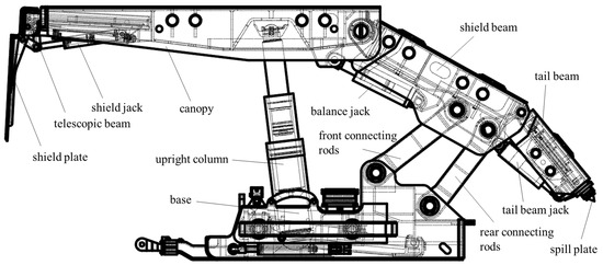
Figure 1.
The main structure of the hydraulic support.
The key technical parameters of the ZFY12000/21/36D hydraulic support are presented in Table 1.

Table 1.
Technical parameters of ZFY12000/21/36D hydraulic support.
To accurately detect the spatial position and orientation of hydraulic supports, a Denavit–Hartenberg (DH) coordinate system was established based on the main structural model of the hydraulic support, as illustrated in Figure 2 The key reference points and parameters are defined as follows:
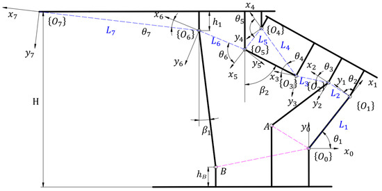
Figure 2.
Hydraulic support DH spatial coordinate system.
Point A: Hinge joint between the base and front connecting rod.
Point B: Hinge joint between the base and upright column.
Angle : Inclination angle between column centerline and vertical direction.
Angle : Deflection angle between column centerline and plumb line.
Distance : Vertical span from canopy upper plate to hinge joint (Point C) between column and canopy.
Distance : Vertical span from base lower plate to hinge joint (Point B) between column and base.
The parameter table of D-H joint coordinate systems is shown in Table 2. The axis direction of coordinate system is horizontally to the right. The xi axis directions of coordinate systems to all follow the distance between coordinate system and coordinate system , and point from coordinate system to coordinate system . The axis directions of the hinge points of hydraulic support to are the axis directions of each coordinate system. The axis directions of coordinate systems to are determined according to the right-handed Cartesian coordinate system rule.

Table 2.
D-H parameters table for joint coordinate systems.
The pose parameters of the DH spatial coordinate system of the hydraulic support are shown in Table 3. In DH theory, the link offset distance and twist angle represent the translational distance along the Z-axis and the rotational angle between adjacent links, respectively. However, in the kinematic operations of the hydraulic support examined in this study, the movements primarily occur within the XY plane without involving displacement or rotation along the Z-axis. Therefore, the corresponding DH parameters were set to zero. The joint angle is the angle between the axis and the axis about the axis. The link offset distance is the distance along the axis from the origin of the coordinate system to the axis. The link length is the distance between the axis and the axis along the axis. The twist angle is the angle between the axis and the axis about the axis.

Table 3.
Hydraulic support D-H spatial coordinate system pose parameter table.
The mapping relationship of coordinate system relative to the reference coordinate system is shown in Equation (1).
In the Equation: and represent the coordinates of the origin in the coordinate system relative to the base coordinate system .
The relationship between the angle formed by the centerline of the column and the vertical direction of the column, and the angle formed by the centerline of the balancing cylinder and the vertical direction of the balancing cylinder, is shown in Equation (2).
4. Orientation of the Fully Mechanized Hydraulic Support
4.1. Pose Transformation in DH Coordinate System
In the spatial coordinate system, the coordinate system can be made to coincide with the coordinate system by rotation and movement. As shown in Figure 3(1), in three-dimensional space, the spatial coordinate system is established, and the axis of the coordinate system is perpendicular and intersecting with the axis, the angle between the axis and the axis about the axis is , and the angle between the axis and the axis about the axis is . The distance from the origin of the coordinate system to the axis along the axis is , and the distance between the axis and the axis along the axis is . Based on this, the coordinate system is established, and the coordinate system is transformed into the coordinate system through rotation and translation. The matrix transformation steps are as follows:

Figure 3.
DH coordinate system matrix transformation.
The coordinate system rotates degrees around the axis, making the axis parallel to the axis, as shown in Figure 3(2).
The coordinate system is moved along the axis by a distance of , so that the axis coincides with the axis, as shown in Figure 3(3).
The coordinate system is moved along the axis by a distance of , so that the origin of the coordinate system coincides with the origin of the coordinate system , as shown in Figure 3(4).
The coordinate system rotates around the axis by degrees, so that the coordinate system coincides with the coordinate system , as shown in Figure 3(5).
The matrix transformation relationship between the coordinate system and the coordinate system is shown in Equation (3).
In the equation: is a 4th-order determinant, representing the transformation relationship between the coordinate system and the reference coordinate system regarding the posture and coordinates. represents the rotation of the coordinate system around the axis by an angle of , indicates the movement of the coordinate system along the axis by a distance of , indicates the movement of the coordinate system along the axis by a distance of , represents the rotation of the coordinate system around the axis by an angle of , is a 3rd-order determinant, representing the transformation relationship between the coordinate system and the reference coordinate system , and is a matrix, representing the transformation relationship between the coordinate system and the reference system .
4.2. Dynamic Positioning Space and Coordinate Solution of Hydraulic Supports
The spatial pose transformation relationship of the hydraulic support is shown in Figure 4. The spatial coordinates of the dynamic model of the hydraulic support are obtained by converting through the forward kinematic matrix, and the end pose of the dynamic model is obtained by converting through the inverse kinematic matrix. In the kinematic solution, is the homogeneous transformation matrix of the transformation joint relative to the transformation joint, and is the transformation matrix of the transformation joint relative to the reference joint. The reference joint is obtained by transforming through the multiple pose transformation matrix to the position of the end joint , and the position and posture of the end effector are solved to achieve the mapping from the joint space to the Cartesian space. In the inverse kinematic solution, is the homogeneous transformation matrix of the transformation joint relative to the transformation joint, and the posture of the reference joint is inversely solved by the spatial coordinates of the end coordinate system to achieve the mapping from the Cartesian space to the joint space.
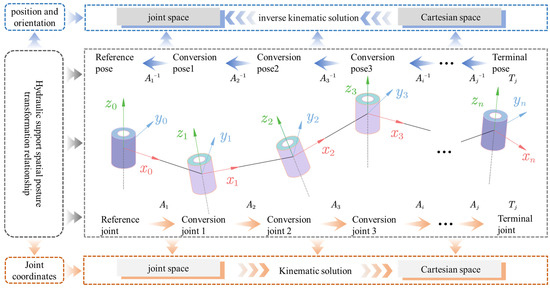
Figure 4.
Hydraulic support spatial position and orientation transformation relationship diagram.
Equation (4) defines the transformation matrix , which maps positions and orientations between joint coordinate system and reference coordinate systems .
In the Equation: is a 3rd-order determinant, representing the pose mapping relationship between the coordinate system and the reference coordinate system . is a matrix, indicating the coordinate mapping relationship between the coordinate system and the reference coordinate system . represents the three-dimensional coordinates of the origin of the coordinate system relative to the reference coordinate system .
The mapping relationship between the length H2 of the balancing cylinder and the height H1 of the column in the spatial coordinate system is shown by Equation (5).
In the Equation: and are the coordinates of the hinge point of the top beam and the balance jack in the base coordinate system . and are the coordinates of the hinge point of the shielding beam and the balance jack in the base coordinate system . and are the coordinates of the hinge point of the top beam and the column in the base coordinate system . and are the coordinates of the hinge point B of the base and the column in the base coordinate system .
The ZFY12000/21/36D hydraulic support has a designed height range of 2100–3600 mm, while in actual coal mining applications, it typically operates within a height range of 3000–3600 mm, which ensures optimal support performance and stability. Accordingly, this study focuses on analyzing the correlation characteristics between the support height and the lengths of the strut and balancing jack within this specified range. Figure 5a shows the analysis diagram of the parameter coupling characteristics among the balancing jack, strut, and support height during the operation of the ZFY12000/21/36D hydraulic support. The X-axis represents the support height of the hydraulic support, the Y-axis represents the height of the column, and the Z-axis represents the length of the balance jack. The red scattered points represent the mapping relationship between the support height and the column height, the green scattered points represent the mapping relationship between the support height and the length of the balance jack, and the blue scattered points represent the mapping relationship between the column height and the length of the balance jack. As the support height increases, the column height also increases. To maintain the balance of the top beam of the hydraulic support, the length of the balance jack decreases. During the lifting operation of the hydraulic support, the variation relationship of joint angle to in the hydraulic support is shown in Figure 5b Since joint angles 3, 4, 6, and 7 are internal joint angles, the number of joint angles remains unchanged during the lifting operation of the hydraulic support. While joint angles 1, 2, and 5 are external connecting joint angles, the degrees of joint angle 1, joint angle 2, and joint angle 5 increase during the lifting operation of the hydraulic support.
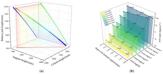
Figure 5.
Analysis diagram of the coupling characteristics of spatial position and orientation parameters of the hydraulic support. (a) The coupling characteristic analysis diagram of the balance jack-column-support height parameters. (b) The variation characteristics of joint angle to in the hydraulic support.
The mapping relationship between joint angles to of the hydraulic support and coordinate systems to is mathematically defined by Equation (6).
5. Analysis of Hydraulic Support Load-Bearing Behavior Under Inclined–Declined and Large-Dip-Angle Working Conditions
During support operations of hydraulic supports, the loads imposed on the structure are predominantly borne by upright columns and balance jacks. However, due to the complexity of underground coal mining conditions, hydraulic supports frequently operate at inclined–declined and large dip angles. The spatial relationship diagram illustrating hydraulic support positions under these multi-angle conditions is shown in Figure 6. Therefore, this section investigates the dynamic load-bearing characteristics of hydraulic supports under both standard working conditions and complex multi-angle scenarios, specifically examining the load response mechanisms of upright columns and balance jacks within angular ranges of 0° to 15° for inclined conditions, 0° to 15° for declined conditions, and 40° to 60° for large-dip-angle conditions.

Figure 6.
Spatial configuration diagram of hydraulic supports under inclined–declined and large dip conditions. (a) Inclined angle. (b) Declined angle. (c) Large dip angle.
5.1. Analysis of Hydraulic Support Load Characteristics Under Standard Pose Conditions
Under standard operating conditions, the hydraulic support canopy simultaneously sustains concentrated loads and supporting forces, with its free-body mechanical model illustrated in Figure 7 incorporating these critical parameters: denotes the concentrated load on the canopy, represents the frictional coefficient between canopy and overlying strata, marks the articulation point between canopy and shield beam, defines the horizontal distance from load to point , measures the horizontal distance between the canopy-column articulation point and canopy-balance jack articulation point, specifies the horizontal distance from balance jack articulation point to , indicates the vertical distance from column articulation point to canopy upper plate, signifies the vertical distance from balance jack articulation point to canopy upper plate, determines the vertical distance from to canopy upper plate, designates the load on upright column, denotes the load on balance jack, characterizes the angle between column centerline and its vertical direction, and defines the angle between balance jack centerline and its vertical direction.
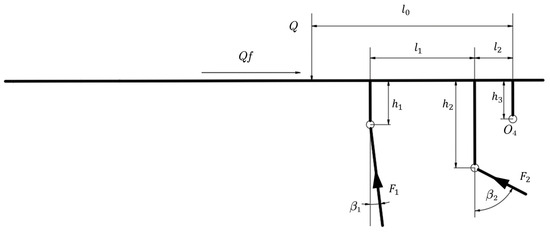
Figure 7.
Top beam force-bearing model.
The horizontal distance from the concentrated force acting point on the canopy to Point is set as 0.35 times the canopy length (0.35), as specified in the hydraulic support design manual. This acting point’s maximum offset was verified to be 19.5 mm through field measurements at the coal mine. The friction coefficient f between the canopy and the overlying rock ranges from 0.15 to 0.3. Given that both the strut load and the balancing jack load exhibit a positive correlation with the friction coefficient, this study adopts the maximum friction coefficient value of 0.3 to investigate the force states of the strut and balancing jack under extreme load conditions.
Equilibrium equations are formulated with respect to the canopy-shield beam articulation point O4 as expressed in Equation (7).
Employing the canopy and shield beam as isolated free bodies, the mechanical model illustrated in Figure 8 establishes these essential parameters: denotes the virtual hinge point formed by the intersection of front and rear connecting rod extensions, defines the spatial distance between articulation points and , represents the horizontal projection angle between these hinge points, while the coordinate–angle relationship at hinge node is governed by Equation (8).
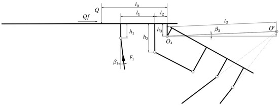
Figure 8.
Mechanical model of canopy and shield beam.
The symbols in the equations are defined as follows: and denote the coordinates of hinge point , and represent the coordinates of the hinge joint between the base and front connecting rod, and is the joint angle of Link 1.
Equilibrium equations are formulated with respect to articulation point O′ as expressed in Equation (9).
The relationship between balance jack load and upright column load is defined by Equation (10).
The hydraulic support studied in this paper is the ZFY12000/21/36D model currently deployed in Wangjiashan Coal Mine and Jianxin Coal Mine. Based on the operating conditions of the support, the canopy load range was determined as 4000–10,000 KN. Accordingly, the load-bearing characteristics of the hydraulic support under different working conditions were solved and analyzed. The three-dimensional force surface diagram of the balance cylinder and the column in the normal posture working condition of the hydraulic support is shown in Figure 9. The X-axis of the coordinate axis represents the load borne by the top beam, the Y-axis represents the support height of the hydraulic support, and the Z-axis represents the load characteristics of the balance cylinder or the column. For the balance jack shown in Figure 9a, its thrust demonstrates a negative correlation with support height, exhibiting a monotonically decreasing trend as height increases, while showing a positive correlation with canopy load, displaying a monotonically increasing trend under elevated loads; at the specific condition of 10,000 KN canopy load, the thrust ranges from 2430 to 2900 KN. Regarding the upright column illustrated in Figure 9b, its thrust maintains minimal correlation with support height, remaining essentially constant across height variations, yet exhibits a positive correlation with canopy load, increasing monotonically with higher loads; under the 10,000 KN canopy load condition, the thrust ranges from 10,580 to 10,700 KN.
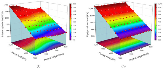
Figure 9.
Three-dimensional load-bearing surface plot of the balance jack and upright column assembly in hydraulic supports under standard pose conditions. (a) Three-dimensional load-bearing diagram of balance jack under standard working conditions. (b) Three-dimensional load-bearing diagram of upright column under standard working conditions.
5.2. Analysis of Load Characteristics of Hydraulic Supports Under Inclined Angle Conditions
During the operations of pushing the AFC (armored face conveyor) and shifting the support in hydraulic supports, the complex coal mining environment leads to base plate inclination. When the base plate tilts upward, inclined mining conditions occur. Based on the actual operating conditions and angle measurements of hydraulic supports at Wangjiashan Coal Mine, the inclination angle range during inclined mining was set to 0–15°. Under inclined angle conditions ranging from 0° to 15°, the concentrated load on the canopy of the hydraulic support generates a component force along the canopy direction, with both the canopy and base respectively bearing loads and supporting forces; establishing a mechanical model using the canopy as a free body as illustrated in Figure 10.
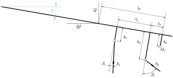
Figure 10.
Mechanical model of canopy under inclined angle conditions.
Equilibrium equations are formulated with respect to articulation point as expressed in Equation (11).
Taking both the canopy and shield beam as free bodies, a mechanical model is established as illustrated in Figure 11.
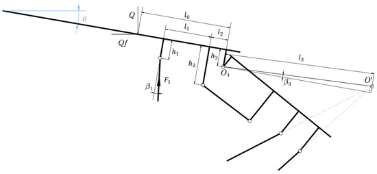
Figure 11.
Mechanical model of canopy-shield beam assembly under inclined angle conditions.
Equilibrium equations are formulated with respect to articulation point as expressed in Equation (12).
The relationship between balance jack load and upright column load is defined by Equation (13).
Figure 12 presents the three-dimensional load-bearing diagrams of the balance jack and upright column in hydraulic supports under inclined angle conditions, with the X-axis representing canopy load, the Y-axis indicating the inclined angle of the hydraulic support, and the Z-axis signifying the load characteristics of either component. For the balance jack shown in Figure 12a, under fixed inclination conditions, its load exhibits a monotonically decreasing trend with increasing canopy load; under fixed canopy load conditions, the balance jack load similarly decreases monotonically as the inclined angle increases. At the specific condition of 10,000 KN canopy load, the thrust ranges from 860 to 2650 KN, where the minimum thrust occurs at maximum declined angle conditions while the maximum thrust arises at minimum declined angle conditions. For the upright column illustrated in Figure 12b, under fixed inclination conditions, its load shows a monotonically decreasing trend with rising canopy load; under fixed canopy load conditions, the column load likewise decreases monotonically with increasing inclined angle. At 10,000 KN canopy load, the thrust ranges from 9280 to 10,620 KN, with its minimum occurring at maximum inclined angle conditions and the maximum emerging at minimum inclined angle conditions.
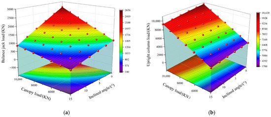
Figure 12.
Three-dimensional load-bearing diagram of balance jack and upright column assembly under inclined angle conditions. (a) Three-dimensional load-bearing diagram of balance jack under inclined angle conditions. (b) Three-dimensional load-bearing diagram of upright column under inclined angle conditions.
5.3. Analysis of Load Characteristics of Hydraulic Supports Under Declined Angle Conditions
During the operations of pushing the AFC (armored face conveyor) and shifting the support in hydraulic supports, the complex coal mining environment leads to base plate inclination. When the base plate tilts downward, declined mining conditions occur. Based on the actual operating conditions and angle measurements of hydraulic supports at Wangjiashan Coal Mine, the inclination angle range during declined mining was therefore set to 0° to 15°. Under declined angle conditions ranging from 0° to 15°, the canopy and base of the hydraulic support, respectively, bear loads and supporting forces, establishing a mechanical model using the canopy as a free body as depicted in Figure 13.
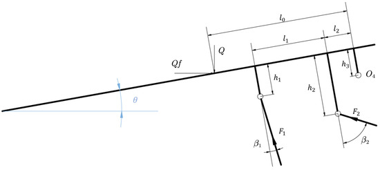
Figure 13.
Mechanical model of canopy under declined angle conditions.
Equilibrium equations are formulated with respect to the articulation point between canopy and shield beam as expressed in Equation (14).
Taking the canopy and shield beam as free bodies, a mechanical model is established as illustrated in Figure 14.
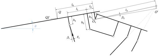
Figure 14.
Mechanical model of canopy-shield beam assembly under declined angle conditions.
Equilibrium equations are formulated with respect to articulation point O′ as expressed in Equation (15).
The relationship between balance jack load and upright column load is derived through simplification and solution, as expressed in Equation (16).
Figure 15 illustrates the three-dimensional load-bearing diagrams of the balance jack and upright column in hydraulic supports under declined angle conditions, with the X-axis representing canopy load, the Y-axis indicating the declined angle of the hydraulic support, and the Z-axis signifying the load characteristics of either component. For the balance jack shown in Figure 15a, under fixed conditions, its load exhibits a monotonically increasing trend with increasing canopy load; under fixed canopy load conditions, the balance jack load similarly increases monotonically as the declined angle increases. At the specific condition of 10,000 KN canopy load, the thrust ranges from 2650 to 4260 KN, where the minimum thrust occurs at minimum declined angle conditions while the maximum thrust arises at maximum declined angle conditions. For the upright column depicted in Figure 15b, under fixed inclination conditions, its load demonstrates a monotonically increasing trend with rising canopy load; under fixed canopy load conditions, the column load likewise increases monotonically with increasing declined angle; at 10,000 KN canopy load, the thrust ranges from 10,620 to 11,240 KN, with its minimum occurring at minimum declined angle conditions and the maximum emerging at maximum declined angle conditions.
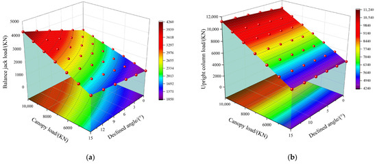
Figure 15.
Three-dimensional load-bearing diagram of balance jack and upright column assembly under declined angle conditions. (a) Three-dimensional load-bearing diagram of balance jack under declined angle conditions. (b) Three-dimensional load-bearing diagram of upright column under declined angle conditions.
5.4. Analysis of Load Characteristics of Hydraulic Supports Under Large-Dip-Angle Working Conditions
Under large-dip-angle loading conditions, hydraulic supports exhibit differential loads on opposing sides of their upright columns, with this load disparity intensifying as the support’s dip angle increases; the mechanical model for such scenarios is depicted in Figure 16, in which represents the load on the non-tilted side, denotes the distance from its action point to the x-axis, signifies the load on the tilted side, and indicates the eccentricity distance relative to the symmetric plane.
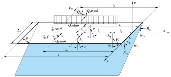
Figure 16.
Mechanical model under large-dip-angle working conditions.
The mechanical equations of hydraulic supports under large-dip-angle working conditions are expressed by Equation (17).
Assuming equal force components along the x-axis at the canopy-shield beam articulation pins, , a non-homogeneous system of linear equations is established for the solution as expressed in Equation (18). Here, matrix corresponds row-wise to each equation, column vector denotes the unknown variables, and constraint vector specifies the boundary conditions.
The relationship between upright column load and balance jack load under large-dip-angle conditions of hydraulic supports is given by Equation (19). To determine the load-bearing status of upright columns and balance jacks under extreme operating conditions, the distance from eccentric load to the central cross-section of the hydraulic support is set to its maximum value of 800 mm, with the loading span of eccentric load equaling the canopy length of 1650 mm.
Figure 17 presents the three-dimensional load-bearing characteristics of upright columns and balance jacks in hydraulic supports under large-dip-angle conditions, with the X-axis denoting total canopy load, the Y-axis indicating support dip angle, and the Z-axis representing load characteristics of respective components; for the balance jack shown in Figure 17a, thrust exhibits positive correlations with both total canopy load and dip angle, monotonically increasing with their augmentation, yielding a thrust range of 3020 to 3440 KN at 10,000 KN canopy load where minimum thrust occurs at minimum dip angle and maximum thrust at maximum dip angle; for the non-tilted side column depicted in Figure 17b, thrust demonstrates positive correlations with canopy load and dip angle, monotonically increasing with their growth, resulting in a thrust range of 6220 to 6280 KN at 10,000 KN canopy load and 60° dip angle with minimum thrust at minimum dip angle and maximum thrust at maximum dip angle; for the tilted side column illustrated in Figure 17c, load decreases significantly with increasing dip angle, transitioning from compression to tension, where at smaller dip angles, load increases with canopy load as compressive thrust, while at larger dip angles, load direction reverses from thrust to tension with tensile load amplifying under increased canopy load, specifically at 10,000 KN canopy load achieving peak thrust of 2780 KN at 40° dip angle and peak thrust of 980 KN at 60° dip angle.

Figure 17.
Three-dimensional load-bearing diagram of balance jack and column assembly under large-dip-angle working conditions. (a) Three-dimensional load-bearing diagram of balance jack under large-dip-angle working conditions. (b) Three-dimensional load-bearing diagram of non-tilted side column under large-dip-angle working conditions. (c) Three-dimensional load-bearing diagram of tilted side column under large-dip-angle working conditions.
6. Case Verification
The ZFY12000/21/36D hydraulic support has been deployed in multiple coal mines including Wangjiashan and Jianxin, with its operational status in coal mines illustrated in Figure 18. It uses inclinometers to measure the inclined, declined, and large-dip-angle positions of hydraulic supports along with link inclination angles; employs laser sensors to measure support height, column height, and balance ram stroke; utilizing pressure sensors to monitor working loads on columns and balance rams; and integrates pose and load data collected from laser sensors, inclination sensors, and pressure sensors via a signal expander.
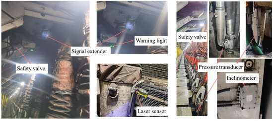
Figure 18.
Actual operational state diagram of hydraulic support in underground coal mine.
This study selects 200 sets of pose parameters of hydraulic supports at varying working heights and inclination angles, quantifying the error magnitude between measured and theoretically solved inclination values using Root Mean Square Error (RMSE) as expressed in Equation (20).
In this equation: denotes the actual measured value, and represents the theoretical solved value.
Figure 19 presents comparative diagrams of measured versus calculated data for hydraulic supports under varying poses. Specifically, Figure 19a illustrates the comparison between measured and calculated inclination angles at different working heights, while Figure 19b demonstrates the contrast between measured inclination angles and calculated poses under varying inclination conditions.
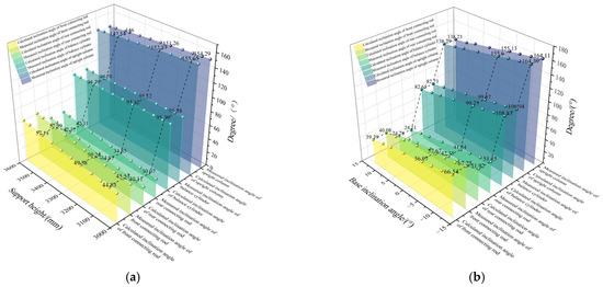
Figure 19.
Comparative diagram of measured versus calculated hydraulic dynamic pose data. (a) Variation comparison between measured and calculated inclination angles at different working heights. (b) Error comparison between measured and calculated inclination angles under varying inclination conditions.
The RMSE between measured and calculated inclination angles of the hydraulic support is presented in Table 4.

Table 4.
RMSE value between measured and calculated inclination angles of hydraulic supports.
Figure 20 depicts the hydraulic support test platform. Industrial electric thrusters from Boschart actuate load-bearing components including upright columns and balance jacks, while Boschart electric thrusters drive jacks for the shield plate, telescopic beam, and tail beam sections. SBT673 column-type tension–compression sensors installed at the base of both upright columns measure column loads, and SBT620 tension–compression sensors mounted at hinge points of the balance jack monitor its loads. BRT38-0.5M-R0M4096-RT1 wire-rope displacement sensors quantify support height along with stroke lengths of columns and balance jacks. HDA436VU-485-BIN-EV inclinometers measure the inclination angles of both the complete hydraulic support system and its individual components. Four lifting supports and tension–compression sensors installed on the upper canopy apply and measure loads on the canopy. Jacks positioned beneath the support base adjust the inclination angle of the hydraulic support baseplate.
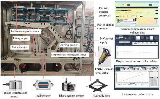
Figure 20.
Hydraulic support test platform.
The data correlation mapping model for hydraulic supports’ physical model–DH model and test platform is illustrated in Figure 21. Using the ZFY12000/21/36D hydraulic support as the physical entity, the DH model is established through key structural data extraction and simplification, while the hydraulic support test platform is constructed via 1:8 geometrically scaled reconstruction. This integrated model incorporates information parameters from displacement sensors, inclinometers, and tension–compression sensors, solving pose space and coordinate space data through matrix iteration and kinematic solving.
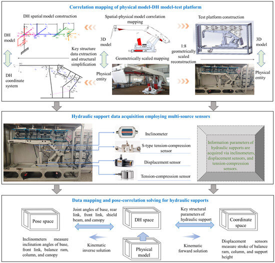
Figure 21.
The data correlation mapping model for hydraulic supports’ physical model–DH model and test platform.
The accuracy ranges and precision classes of sensors used in the hydraulic support test platform are listed in Table 5.

Table 5.
Parameters table of sensors used in the hydraulic support test platform.
Figure 22 illustrates the pose state diagram of the hydraulic support test platform under inclined–declined and large-dip-angle working conditions. The operational states under varying angular conditions are simulated by adjusting the height of jacks beneath the support base, while coal seam loads acting on the hydraulic support are replicated through lifting supports and tension–compression sensors installed on the canopy.
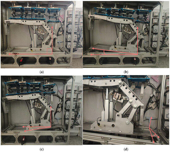
Figure 22.
The pose state diagram of the hydraulic support test platform. (a) Standard pose conditions. (b) Inclined angle conditions. (c) Declined angle conditions. (d) Large-dip-angle conditions.
Due to the limited variability of actual data on canopy loads, and inclined–declined and large-dip-angle conditions of hydraulic supports in underground coal mines, it is challenging to fully validate the accuracy and generalization capability of the proposed method. To address this, we independently constructed a hydraulic support test platform to systematically collect force data from struts and balancing jacks under various external loads and inclination angles, which were then compared with theoretical solutions. The comparison between experimental data and theoretical results is shown in Figure 23, where the surface represents the theoretical predictions and the blue scatter points correspond to the experimental data. The figure demonstrates strong consistency between the theoretical solutions and experimental data on the test platform.
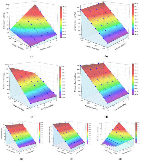
Figure 23.
Comparison diagram of theoretical solutions and experimental data. (a) Balance jack load under inclined angle conditions. (b) Upright column load under inclined angle conditions. (c) Balance jack load under declined angle conditions. (d) Upright column load under declined angle conditions. (e) Balance jack load under large-dip-angle conditions. (f) Non-tilted column load under declined angle conditions. (g) Upright column load under declined angle conditions.
Analysis indicates that the strut, with its small angle to the vertical direction, exhibits a clear linear relationship between its force and the canopy load. In contrast, the balancing jack, with its larger angle to the vertical direction combined with the load distribution offset caused by support inclination, demonstrates a relatively weaker linear relationship with the canopy load.
Due to factors such as the self-weight of the hydraulic support test platform and the center offset caused by the tilting of the hydraulic support, errors have occurred between the experimental results and the theoretical solutions. The RMSE values between the experimental results of the hydraulic support test platform and the theoretical solutions are shown in Table 6.

Table 6.
RMSE values between theoretical solutions and experimental data of the hydraulic support test platform.
7. Conclusions and Future Work
Aiming at the stability and safety issues of hydraulic supports caused by uneven evolution of pose and load under inclined–declined and large-dip-angle mining conditions, a mathematical model of pose–load coupling for hydraulic supports is proposed, providing a theoretical framework for identifying core safety support states. The model accurately describes the mechanical behavior of the supports under various working conditions. By comparing with real-time monitored load data from struts and balancing jacks, it enables dynamic assessment and early warning of the working face safety status, thereby significantly enhancing the safety controllability of the support system. The primary innovative contributions are as follows:
This study proposes a three-layer pose mapping method for hydraulic supports across physical space-geometric coordinate system-DH parameter space. Based on Denavit–Hartenberg (DH) theory, matrix iteration, and kinematic simulation, this method constructs a hydraulic support pose model that standardizes mapping relationships between spatial coordinate systems and joint parameters. It achieves unified modeling and precise geometric description of complex structures and movements in hydraulic supports.
This study proposes a load-bearing characteristic analytical approach for hydraulic supports operating under inclined, declined, and large-dip-angle mining conditions. Grounded in systematic coupling analysis of dip angle, pose, and load distribution, this method employs multi-source parameter fusion to resolve the dynamic evolution mechanisms of hydraulic supports under abnormal postures and load-bearing states, thereby elucidating co-evolution patterns of load-bearing performance in multi-source strong-disturbance mining scenarios.
Using the ZFY12000/21/36D hydraulic support as the physical entity, a 1:8 geometrically scaled test platform was constructed. Inclination, displacement, and tension–compression sensors were installed to collect pose and load data under multi-factor coupled dynamic conditions, validating the proposed method’s effectiveness. Results demonstrate substantial consistency between experimental outcomes and theoretical evolution patterns.
Despite the promising results demonstrated by the proposed dynamic pose–load co-evolution solution method for hydraulic supports under inclined, declined, and large-dip-angle mining conditions in both theoretical and experimental studies, further research is warranted. Future directions include (1) developing a visualization system for dynamically mapping stability boundaries during the pose–load co-evolution process; (2) the pose–load coupling relationships precisely quantified through our experiments that will serve as authentic data for training the LSTM model, thereby enabling the prediction of future states of hydraulic supports and the optimization of control strategies; (3) creating a hybrid decision-making framework combining knowledge reasoning and data-driven approaches to develop adaptive control strategies for hydraulic supports operating in high-disturbance mining scenarios.
Supplementary Materials
The following supporting information can be downloaded at: https://www.mdpi.com/article/10.3390/math13182945/s1, Complete accompanying data have been provided for the 18 figures and tables in the pa-per, which are included as Supplementary Materials, along with explanatory notes for some of the figures.
Author Contributions
Conceptualization, L.H.; Writing—original draft, L.S.; Writing—review & editing, Y.W., Z.Z., Z.Y., H.C., J.L., X.C. and X.Z. All authors have read and agreed to the published version of the manuscript.
Funding
This research was supported by the China National Natural Science Foundation 52204174, China Postdoctoral Science Foundation 2022MD723828, Shaanxi Postdoctoral Science Foundation 2023BSHTBZZ44, Shaanxi University Youth Innovation Team Foundation 23JP096.
Data Availability Statement
The original contributions presented in this study are included in the article/Supplementary Materials. Further inquiries can be directed to the corresponding authors.
Conflicts of Interest
The authors declare no conflict of interest.
References
- Ge, S.; Zhang, X.; Xue, G.; Ren, H.; Wang, H.; Pang, Y.; Fan, L. Development of intelligent technologies and machinery for coal mining in China’s underground coal mines. Strateg. Study CAE 2023, 25, 146–156. [Google Scholar] [CrossRef]
- Wang, G.; Xu, Y.; Ren, H.; Zhang, D.; Pang, Y. Development and innovation practice of China coal mining technology and equipment for 50 years: Commemorate the 50th anniversary of the publication of Coal Science and Technology. Coal Sci. Technol. 2023, 51, 1–18. [Google Scholar]
- Wang, G.; Pang, Y.; Xu, Y.; Meng, L.Y.; Han, H.J. Development of intelligent green and efficient mining technology and equipment for thick coal seam. J. Min. Saf. Eng. 2023, 40, 882–893. [Google Scholar]
- Li, W.; Sun, X. Key technologies and practices for safe, efficient, and intelligent mining of deep coal resources. Coal Sci. Technol. 2024, 52, 52–64. [Google Scholar]
- Wu, Y.; Lang, D.; Yun, D.; Xie, P.; Wang, H.; Gao, X.; Luo, S.; Zeng, Y.; Lyu, W.; Liu, B.; et al. Reform and prospects of mining technology for large inclined coal seam in China. Coal Sci. Technol. 2024, 52, 25–51. [Google Scholar]
- Dawid, S. Research on the Strain and Stress of Powered Roof Support Construction to Limit Damage. Machines 2024, 12, 940. [Google Scholar] [CrossRef]
- Rak, Z.; Stasica, J.; Burtan, Z.; Chlebowski, D. Technical Aspects of Mining Rate Improvement in Steeply Inclined Coal Seams: A Case Study. Resources 2020, 9, 138. [Google Scholar] [CrossRef]
- Jia, H.; Zhang, Z.; Liu, S.; Peng, B.; Yu, H.; Shao, S.; Wang, Y. Research on dissimilation characteristics and control method of failure of surrounding rock in the roadway with repeated mining of steep and ultra-close multiple coal seam. Coal Sci. Technol. 2025, 53, 68–80. [Google Scholar]
- Chen, H.; Chen, H.; Xu, Y.; Zhang, D.; Ma, Y.; Mao, J. Research on attitude monitoring method of advanced hydraulic support based on multi-sensor fusion. Measurement 2022, 187, 110341. [Google Scholar] [CrossRef]
- Zeng, Q.; Li, Z.; Wan, L.; Ma, D. Study on Roof Instability Effect and Bearing Characteristics of Hydraulic Support in Longwall Top Coal Caving. Appl. Sci. 2023, 13, 8102. [Google Scholar] [CrossRef]
- Ji, Y.; Zhang, Y.; Huang, Z.; Shao, Z.; Gao, Y. Theoretical Analysis of Support Stability in Large Dip Angle Coal Seam Mined with Fully-Mechanized Top Coal Caving. Min. Sci. 2020, 27, 73–87. [Google Scholar]
- Chen, N.; Fang, X.; Liang, M.; Xue, X.; Zhang, F.; Wu, G.; Qiao, F. Research on Hydraulic Support Attitude Monitoring Method Merging FBG Sensing Technology and AdaBoost Algorithm. Sustainability 2023, 15, 2239. [Google Scholar] [CrossRef]
- Jiang, B.; Han, L.; Zhao, L.; Pang, Q.; Gao, Q.; Du, N. Reliability analysis of 50000 kN hydraulic support test bench under shrinkage test conditions. J. Vibroeng. 2024, 26, 1699–1713. [Google Scholar] [CrossRef]
- Luo, S.; Wu, Y.; Xie, P.; Wang, H.; Zhang, H. Mechanical analysis of support stability in longwall mining of steeply Declined seam. J. China Coal Soc. 2019, 44, 2664–2672. [Google Scholar]
- Liang, M.; Li, K.; Fang, X.; Zheng, D.; Lu, X.; Wu, G.; Lu, H. Development of FBG Inclination Sensor: A Study on Attitude Monitoring of Hydraulic Supports in Coal Mines. Appl. Sci. 2025, 15, 3429. [Google Scholar] [CrossRef]
- Chen, H.; Chen, Q.; Chen, H.; Yang, X.; Wang, X. Measurement of displacement and top beam attitude angle of advanced hydraulic support based on visual detection. Measurement 2023, 219, 113264. [Google Scholar] [CrossRef]
- Chen, H.; Chen, Q.; Yang, X.; Wang, X.; Chen, H. Omni-directional attitude detection of advanced hydraulic support relative to roadway based on visual measurement principle. Opt. Laser Technol. 2024, 179, 111329. [Google Scholar] [CrossRef]
- Zhang, Y.; Zhang, H.; Gao, K.; Zeng, Q.; Meng, F.; Cheng, J. Research on Intelligent Control System of Hydraulic Support Based on Position and Posture Detection. Machines 2022, 11, 33. [Google Scholar] [CrossRef]
- Pang, Y.; Shi, Y. Intelligent control algorithms for posture and height control of four-leg hydraulic supports. Sci. Rep. 2025, 15, 3010. [Google Scholar] [CrossRef]
- Mei, Z.; Wang, X.; Xie, J.; Li, S.; Liu, J. A sensing system and solving method for dynamic detection of relative pose of hydraulic support group. Measurement 2025, 243, 116145. [Google Scholar] [CrossRef]
- Hao, X.; Zhu, C.; Zhang, J.; Ge, S.; Tian, K.; Gao, C. Position and attitude digital twin model of hydraulic supports in fully mechanized workface. J. Mech. Sci. Technol. 2024, 38, 3741. [Google Scholar] [CrossRef]
- Hao, Z.; Xie, J.; Wang, X.; Feng, Z.; Meng, H. A method for reconstructing the pose of hydraulic support group based on point cloud and digital twin. Measurement 2024, 225, 113977. [Google Scholar] [CrossRef]
- He, L.; Xu, T.; Wu, Y.; Gao, J.; Wang, Y.; Pan, R. A Framework of Distributed Hydraulic Support Control System Based on Multi-Agent Systems. In Proceedings of the 2024 IEEE International Conference on Control Science and Systems Engineering (ICCSSE), Beijing, China, 18–20 October 2024; pp. 267–274. [Google Scholar]
- Pan, L.; Duan, Y.; Zhang, Y.; Xie, B.; Zhang, R. A lightweight algorithm based on YOLOv5 for relative position detection of hydraulic support at coal mining faces. J. Real-Time Image Process. 2023, 20, 40. [Google Scholar] [CrossRef]
- Zhang, J.; Wang, X.; Du, R.; Zhao, J.; Liu, J.; Wang, X.; Shen, W.; Xie, J. Method for solving spatial pose of hydraulic support based on autonomous AR measurement by inspector. Proc. Inst. Mech. Eng. Part C J. Mech. Eng. Sci. 2025, 239, 6101–6123. [Google Scholar] [CrossRef]
- Xie, B.; Yang, Y. Study on Working Characteristics of 4-Column Hydraulic Support in Lifting–Lowering–Moving State Based on Microcontact Theory and Rigid–Flexible–Mechanical–Hydraulic Coupling Simulation Model. Actuators 2024, 13, 193. [Google Scholar] [CrossRef]
- Qin, Z.; Yuan, Y.; Mao, Z.; Xu, X.; Li, Y.; Li, L.; Chen, Z.; Li, B. Research on coal gangue transport and shield beam bearing pressure law based on FLAC3D-PFC3D coupled simulation and physical similar simulation. Comput. Part. Mech. 2025, 12, 1–21. [Google Scholar] [CrossRef]
- Lin, F.; Li, M. Dynamic characteristics simulation and optimization of hydraulic support based on CAE method. Vibroeng. Procedia 2024, 57, 39–45. [Google Scholar]
- Cao, L.; Xu, Y.; He, C.; Zhang, E.; Miao, Y. Analysis of the load--bearing characteristics of hydraulic supports for top--coal caving under the impact of coal and gangue. Energy Sci. Eng. 2024, 12, 4810–4822. [Google Scholar] [CrossRef]
- Cao, L.; Yan, P.; Xi, W.; Zhang, X.; Jin, X.; Yang, H. Study on the bearing characteristics of overrun hydraulic support under impact loading. Front. Earth Sci. 2023, 11, 1180389. [Google Scholar] [CrossRef]
- Meng, Z.; Ma, C.; Xie, Y. Influence of impact load form on dynamic response of chock-shield support. Eksploat. I Niezawodn. Maint. Reliab. 2023, 25, 168316. [Google Scholar] [CrossRef]
- Zeng, Q.; Li, Z.; Wan, L.; Ma, D.; Wang, J. Research on Dynamic Characteristics of Canopy and Column of Hydraulic Support under Impact Load. Energies 2022, 15, 4638. [Google Scholar] [CrossRef]
- Hu, X.; Liu, X. Design and analysis of one-degree statically indeterminate hydraulic support. J. Mech. Sci. Technol. 2021, 35, 5529–5539. [Google Scholar] [CrossRef]
- Zhang, J.; Wan, C.; Wang, J.; Chen, C.; Wang, T.; Xu, K. Research on the high precision hydraulic column stress monitoring method. Sci. Rep. 2025, 15, 832. [Google Scholar] [CrossRef]
- Meng, G.-H.; Zhang, J.-X.; Li, M.; Wang, C.-J.; Zhou, N.; Zhang, L.-B. Bearing characteristics and safety control of hydraulic support groups in shallow-buried thin bedrock ultra-long working faces. J. Cent. South Univ. 2023, 30, 1662–1674. [Google Scholar] [CrossRef]
- Xie, P.; Wu, S.; Luo, S.; Wu, Y.; Chen, J. Dynamic instability mechanism of support and its control in longwall mining of steeply Declined coal seam. Coal Sci. Technol. 2023, 51, 58–71. [Google Scholar]
- Hu, X.; Ji, X.; Liu, Y.; Du, Y. Study on instability mechanism of hydraulic support in downdip and updip coal face. Alex. Eng. J. 2023, 81, 304–318. [Google Scholar] [CrossRef]
- Szweda, S.; Szyguła, M.; Szelka, M.; Banaś, M.; Kołodziejczyk, K. Computational Methods for Verifying the Normative Requirements Regarding the Lateral Correction Force of a Powered Roof Support. Energies 2024, 17, 5433. [Google Scholar] [CrossRef]
- Cao, L.; Geng, M.; Shen, R.; Zhang, D.; Zhang, X. Research on Coal-Releasing Characteristics of Hydraulic Support for a Large Inclined-Angle Comprehensive Workface. Machines 2024, 12, 656. [Google Scholar] [CrossRef]
- Bai, S. Research on Attitude Perception of Hydraulic Support and Control of Top Beam Pitch Angle. Master’s Thesis, Taiyuan University of Technology, Taiyuan, China, 2021. [Google Scholar]
- Luo, S.H.; Wang, T.; Tian, C.Y.; Gao, X.C.; Lang, D.; Wang, H.W. Angle effect of the roof stress transmission path in longwall mining of steeply Declined coal seam. J. China Coal Soc. 2022, 47, 623–633. [Google Scholar]
- Xu, Y.; Zeng, M.; Cai, F.; Ding, W.; Liu, J.; Han, H. Investigation on adaptability of two-leg shielded LTCC hydraulic supports for ultra-thick and hard coal seam with super-large cutting height. J. Min. Saf. Eng. 2025, 42, 252–263. [Google Scholar]
Disclaimer/Publisher’s Note: The statements, opinions and data contained in all publications are solely those of the individual author(s) and contributor(s) and not of MDPI and/or the editor(s). MDPI and/or the editor(s) disclaim responsibility for any injury to people or property resulting from any ideas, methods, instructions or products referred to in the content. |
© 2025 by the authors. Licensee MDPI, Basel, Switzerland. This article is an open access article distributed under the terms and conditions of the Creative Commons Attribution (CC BY) license (https://creativecommons.org/licenses/by/4.0/).