Abstract
As MEMS design encounters growing challenges, particularly stiction between movable and stationary electrodes, dielectric charging, pull-in instability, and multi-valued response characteristics, the integration of dimple-equipped structures has emerged as a pivotal solution to mitigate these fundamental issues. Consequently, this study investigates the dynamic behavior of an electrostatically actuated double-clamped microbeam incorporating dimples and contact pads. While the dimples enhance the beam’s travel range, they may also induce an impact mode upon contact with the landing pads, leading to complex nonlinear dynamic phenomena. A reduced-order model was developed to numerically solve the governing equation of motion. The microbeam’s response was analyzed both with and without dimples using multiple analytical techniques, including bifurcation diagrams and discrete excitation procedures near the impacting regime. The findings demonstrate that the inclusion of dimples effectively suppresses stiction, pull-in instability, and multi-valued responses. The results indicate that upon contacting the landing pads, the beam exhibits pronounced nonlinear dynamic behaviors, manifesting as higher-period oscillations such as period-3, period-4 and period-5 and then fully developed chaotic attractors. Indeed, this specifically demonstrates the potential of using the dynamic transition from a steady-state to a chaotic response to build novel MEMS sensors.
MSC:
74H45
1. Introduction
Micro-Electro-Mechanical Systems (MEMS) refers to a production methodology for developing miniaturized structures that combine mechanical and electrical functionalities. These systems are fabricated via sophisticated processes similar to those used in integrated circuit (IC) production, resulting in devices on the scale of micrometers to millimeters. The applicability of MEMS has expanded significantly, becoming critical to sectors such as automotive electronics, medical technology, telecommunications, and defense systems [1,2,3]. MEMS sensors are designed to monitor environmental parameters, transduce these changes into quantifiable signals, and initiate appropriate physical actuation [4,5,6]. This actuation can be excited via electrostatic, electrothermal, or electromagnetic methods. Selecting a suitable actuation mechanism is paramount for operational reliability, since a significant number of device failures are attributed to manufacturing defects and performance-related stresses resulting from the fabrication process itself [7].
Resonance is a critical phenomenon in MEMS, profoundly impacting performance, power efficiency, and actuation frequency. There are two primary types: primary and secondary resonance [8]. Primary resonance arises when the excitation frequency nears a system’s natural frequency, significantly amplifying the actuator’s response [9,10]. Secondary resonance, a nonlinear effect, occurs at harmonic or subharmonic multiples of the drive frequency. This is especially relevant in MEMS, as it can induce complex vibrational modes and unexpected operational behaviors [11]. MEMS devices exhibit significant electromechanical nonlinearities, which introduce major operational challenges like pull-in instability. This critical failure mode occurs when electrostatic forces exceed the system’s mechanical restoring forces, causing the structure to collapse and adhere permanently. This contact between the actuator’s stationary and movable electrodes leads to stiction and dielectric charging, ultimately damaging the device [12]. Consequently, these issues significantly limit the practical use of electrostatic actuation.
To combat stiction, several strategies have been proposed. These include enhancing the structure’s restoring force, employing low-adhesion coatings and chemical surface treatments, and integrating dimples on movable electrodes or stoppers on fixed ones [13,14]. Among these, dimples have seen widespread adoption in MEMS to tackle key challenges. By creating controlled contact pads, strategically placed dimples minimize adhesion while preserving electrical contact. The nonlinearity of electrostatic forces intensifies with large displacements, causing significant deviations from linear behavior a well-known phenomenon in MEMS. In addition to traditional methods like curved beams, closed-loop control, mechanical magnification, and repulsive forces, dimple integration has emerged as an effective strategy to extend the stable operational range of electrostatic actuators [15,16,17]. However, dimples introduce their own dynamic challenges: the repeated impacts between the dimple and substrate can excite nonlinear vibrations that may escalate into chaos. This behavior, as shown in recent nonlinear analyses, poses critical risks to actuator reliability and performance predictability [18,19].
The study of chaos in MEMS is critically important for understanding nonlinear phenomena [20,21,22]. Researchers have developed various analytical and numerical approaches to predict chaotic behavior in MEMS resonators. The Melnikov technique has proven particularly valuable, offering an analytical criterion for homoclinic orbit through inequality-based predictions [23]. Alternative techniques include perturbation methods, multiple scales and delayed dynamics modeling [24].
Chaotic behavior has been discovered and reported for many physical systems. Such behavior could be beneficial feature in some cases. The transition to a chaotic regime in dynamical systems typically follows specific routes, including period doubling [25], intermittency [26], homoclinic tangles [27], and quasi-periodicity [28]. This behavior is often precipitated by strong nonlinearities. It has been reported across a wide range of devices including, but not limited to, micro-cantilevers for atomic force microscopy [29], comb-drive actuators, microfluidic mixers [30], and components for RF communications and filtering [31].
Researchers have studied the onset of homoclinic and heteroclinic chaos in double-sided actuated beams [32]. A symmetry-breaking bifurcation is one potential mechanism that can lead to this behavior [33]. At the micro-scale, the chaotic phenomena are well-established. For instance, numerical models have predicted and experimentally validated the appearance of the intermittency route to chaos in atomic force microscopy operating in tapping mode [34] and bistable actuators. Furthermore, another study indicates that the emergence of chaotic attractors can be initiated by a secondary resonance excitation mechanism [35]. The chaotic behavior of a micro-beam excited electrostatically by two distinct frequencies has been reported [36]. Their results showed that employing two frequencies enhances the complexity of the chaotic dynamics.
The size effect on chaotic behavior of a micro-electro-mechanical resonator excited electrostatically has been investigated [37]. Barceló et al. [38] studied the minimum requirement to obtain the cross-well chaotic phenomenon of an electrostatically driven in-plain motion-based beam. Their model suggested that tuning mechanical and electrical parameters is a must to achieve a cross-well chaotic motion. The nonlinear response and chaotic behaviors under a random disturbance and electrostatic excitation has been studied through a developed reduced-order model that accounts for the effect of the random disturbance and geometric and force nonlinearities [39].
Recent work has specifically examined chaos prediction in electrostatically actuated arch-shaped micro/nano resonators. These studies employ analytical methods to characterize the transition from periodic to chaotic motion, providing critical insights into the stability boundaries of such systems [40,41]. The development of reliable prediction methodologies enables more effective chaos control strategies, which are essential for ensuring the operational reliability of MEMS devices in practical applications.
The Galerkin method has been effectively employed to analyze nonlinear dynamics in MEMS resonators [42]. Recent studies have applied this methodology to examine chaotic dynamics in electrostatically actuated shallow arch microbeams [43]. Numerical simulations reveal that chaotic attractors emerge near the fundamental frequency, particularly when the curved beam is actuated from its initial counter-curved configuration. This phenomenon demonstrates the sensitive dependence of nonlinear MEMS structures to both initial conditions and excitation parameters. This research presents a microbeam actuator with a dimpled design and contact pads. Using a simplified computational model, the study found that the device can exhibit chaotic vibrations near its primary resonance frequency. This chaos is caused by the physical contact of the dimples with the electrode beneath them.
2. Design, Principle of Operation and Modeling
2.1. Actuator Design and Parameters
The actuator consists of a clamped–clamped beam that is electrostatically excited via an electrode setting underneath it as shown in Figure 1. The system incorporates two dimples integrated with the beam structure, functioning as mechanical stoppers that interact with corresponding substrate-separated contact pads. It has a length of µm, a width of µm, and a structural layer thickness of µm; the gap measured from the stationary substrate to the moving beam is set to µm. The Young’s modulus (E) is set to 129 GPa with its density () set to 2332 kg/m3, respectively. The dimple has a length and width of µm while its thickness is similar to the structural layer thickness. As a result, the available travel range is µm. The beam and contact pads are grounded while the excitation waveform is supplied to the substrate.
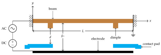
Figure 1.
2D drawing showing the electrostatically actuated double clamped microbeam equipped with dimples and contact pads.
This design prevents stiction and dielectric charging by ensuring that only the grounded dimples on the movable electrode make contact with the pads on the stationary electrode. This maintains a fixed separation gap, denoted as d, between the microbeam itself and the substrate, allowing it to move freely without sticking, as shown in Figure 1.
2.2. Mathematical Modeling
The transverse equation of motion for the beam’s mid-point deflection () is formulated to study the sensor’s dynamic behavior near its fundamental resonance and to investigate how the dimples influence its performance. Toward this, the governing equation of the beam subjected to a distributed electrostatic force can therefore be written as [8]:
The terms in the left-hand side of Equation (1) include three terms corresponding to the beam’s mechanical stiffness, inertial mass, and viscous damping . Meanwhile, the right-hand side consists of two terms: the first accounts for geometric nonlinearities, and the second represents the electrostatic force where () stands for the air permittivity. The area and moment of inertia are denoted by and , respectively. The beam is subjected to the following boundary conditions (BCs):
To model the dimple contact, we employ a restitution coefficient approach. In this model, the fundamental equation of motion remains similar to Equation (1). However, the system’s dynamics become subject to a velocity constraint. This constraint is activated when the dimples contact the pads, causing the velocity () to be reversed and scaled by a factor (e). This relationship can be expressed as follows:
where and denote the moments in time immediately prior to and following the impact event, respectively. When the displacement surpasses the maximum travel displacement demarcated by , the restitution coefficient e indicates the energy dissipation during the impact event. Subsequently, the spatial and time variables shown in the equation of motion are normalized with respect to the capacitor gap and , respectively. This can be peformed by introducing the following nondimensional variables [8]
Substituting these nondimensional variables back into Equation (1) to yield
Thus, multiplying both sides of Equation (3) by () results in
where the nondimensional coefficients are
and the nondimensional BCs are
To solve the governing equation of motion, an approximate method of solutions need to be utilized. Thus, a Galerkin approximation-based reduced-order model is employed to simulate the sensor’s static and dynamic behavior [44]. In this approach, the system’s equation is discretized to a finite number of degrees of freedom. Furthermore, the type and number of mode shapes utilized in the Galerkin expansion affect the solution fidelity. These must satisfy the BCs. Here, the straight beam mode shapes have been used; thus, the general solution of Equation (4) can be written as
where K is the number of modes kept during discretization, are the trial functions, and are the modal coordinates. Subsequently, we multiply both sides of Equation (4) by to reduce the computational time and to avoid singularity. Then, we substitute Equation (6) into the obtained results, multiply it by the mode shape and finally integrate it along the beam’s length. This leads to a set of the differential equations as follows:
3. Results and Discussion
First, a convergence analysis was performed to determine the minimum number of modes required for the Galerkin expansion. This was performed by comparing the static deflection results obtained using models with one, two, and three symmetrical modes. The analysis confirms that higher-mode approximations are necessary for accurate convergence at higher voltages, as models with only one or two modes introduce significant errors near the pull-in instability. However, at lower actuation voltages, a one-mode approximation is sufficient as shown in Figure 2a. Therefore, to optimize computational time while maintaining accuracy within the lower voltage regime of this study, a one-mode reduced-order model (ROM) was adopted for the dynamic analysis.
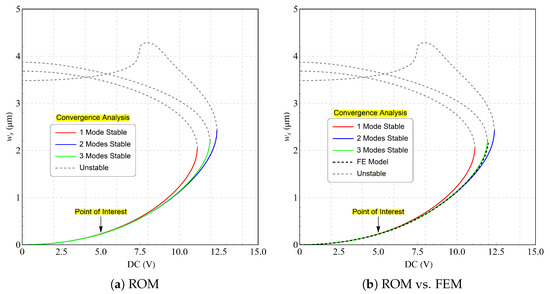
Figure 2.
A convergence analysis to determine the minimum number of modes required in the Galerkin expansion by comparing the static deflection obtained using (a) one-, two-, and three-mode approximation in the reduced-order mode and (b) comparison with FE model.
While convergence analysis typically recommends a five-mode expansion for accuracy near the pull-in threshold where nonlinearities are strong, this study operates under conditions where a one-mode approximation is sufficient [44]. Figure 2a shows a single solution branch with stable and unstable sections. The pull-in instability occurs at approximately 11.6 (V), corresponding to a maximum stable deflection of 2 µm. Beyond this point, the beam collapses and goes into contact the pad. A comparison with the FE model made using COMSOL 5.3 multiphysics shows that a good agreement is obtained through using a three symmetrical mode approximation, as illustrated in Figure 2b.
The dynamic response was characterized by frequency response curves (FRCs) generated near the beam’s first out-of-plane resonant mode. A frequency sweep was performed from 10 to 25 kHz under a constant bias voltage of 5 (V) and a quality factor (Q) of 20. The amplitude of the AC driving voltage was incremented from 1 to 4 (V) in 1 (V) steps. The FRCs were computed via Long-Time Integration (LTI) over a duration of 2000 periods.
Figure 3 illustrates the mid-point displacement as both the signal frequency and voltage increase. This indicates that the beam demonstrates a singular equilibrium and hardening response across all levels of excitation. This is anticipated and is a key trait of a double-clamped beam. The figure further illustrates that the response escalates until it approaches the primary resonance. It is observed that at (V) and (V), the response is entirely nonlinear, showing no evidence of interaction between the dimples and the contact pad, (—). It can also be noted that the mid-point displacement under this excitation condition is nearing the maximum stable allowable deflection.
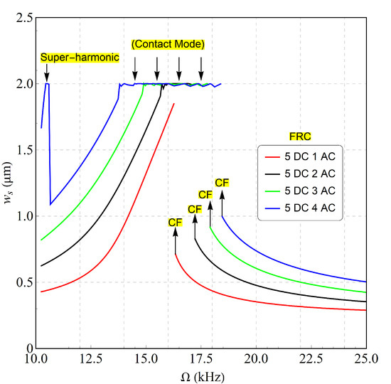
Figure 3.
The simulated FRCs of the beam equipped with the dimples mid-point displacement under different excitation voltage waveforms. The results obtained analytically showing one stable branch of solution for each set of excitation voltage where the maximum allowable stable deflection sets to 2 µm. The response is hardening and the bifurcation points are known as cyclic-folds and are marked as CF.
Similarly, increasing the AC drive voltage to 2 (V) produces a comparable nonlinear response. However, near the primary resonance, the amplified vibration exceeds the stable travel range of 2 µm, indicated by the black line (—). This causes the dimples to impact the contact pads. As a result, the beam enters a contact mode oscillating region within a rebound zone until it eventually exits this state. On the other hand, higher voltages such as 3 (V) and 4 (V) exhibit similar behavior but with an expanded contact band. Notably, the dimples serve as a first line of defense against stiction and dielectric charging. Additionally, when the beam makes contact with the pads, the dynamic response may exhibit chaotic behavior, and therefore this is worth investigating. It is worth noting that the beam jumps up through a cyclic-fold bifurcation at the same time as the frequency sweep-down, indicating that the the response shifts from lower range to a higher stable branch of solution.
To study the visibility of the chaotic behavior, we constructed a bifurcation diagram at an excitation voltage waveform of (V) and (V) in the presence and absence of dimples. The dimple-free scenario was included to compare dynamic responses and to highlight abrupt changes when the beam enters the tapping mode. Taking into account a frequency range of 12.5–27.5 for the case where the dimples are not included in the design and a frequency range of 22.5–24.5 for the case where the dimples are included, respectively, a stacking one-sided Poincaré section of the displacement v as the orbit crosses the velocity axis with a positive slope on the side of the equilibrium point closer to the electrode is obtained. This method is crucial for capturing and characterizing the dynamic response near the tapping mode. Notably, the analysis employs a nondimensional excitation frequency.
In Figure 4a, it can be seen that as the frequency rises and departs from the super-harmonic resonance, a single orbit defined by one period (P-1) is observed. As the frequency of the excitation signal approaches the primary resonance, a sudden alteration in the dynamic oscillation takes place. At this point, the beam physically touches the stationary electrode. The behavior in this region is recognized as a chaotic response, where the beam could not establish a stable equilibrium for its oscillations. Another indication that the beam is losing stability is when the displacement exceeds the maximum stable travel range, 2 µm. This behavior is depicted in the shaded gray area of the bifurcation diagram.
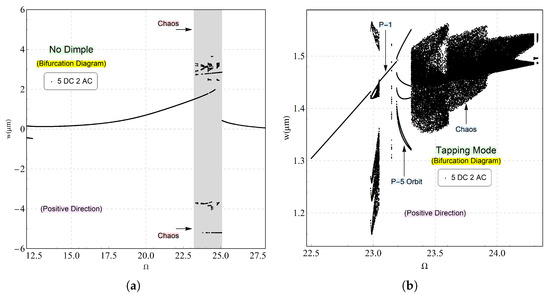
Figure 4.
The bifurcation diagram constructed for an excitation waveform of (V) and (V). It was generated using a one-sided Poincaré section, plotting the displacement v at instances where the velocity crosses zero with a positive slope. This analysis was performed near the fundamental frequency for two specific cases: (a) without dimples and (b) with dimples.
A procedure similar to that in Figure 4b was carried out in the presence of dimples, focusing on the contact mode illustrated in Figure 3. At lower frequencies, a single period-one (P-1) orbit emerges, corresponding to the smooth transition between super-harmonic oscillations and large-amplitude oscillations near primary resonance. However, as the frequency increases into the tapping mode, the dynamics become more complex. The response shifts from stable single-orbit oscillations to a chaotic behavior before returning to a single-orbit state upon exiting the chaotic region. This clearly indicates that the dimples on the beam make direct contact with the pads. The system transitions from stable single-orbit oscillations to chaos before reverting to a single-orbit state, confirming intermittent contact between the dimples and the pads. Additionally, the figure reveals a progression from single-orbit motion to period-five (P-5) orbits and eventually to fully chaotic dynamics as the frequency continues to increase.
To better understand the dynamic response near the tapping mode with dimples and to investigate the behavior of the beam, the equation of motion was numerically solved over a long duration to ensure stability and steady-state conditions. The Fast Fourier Transforms (FFT), and phase portraits were then analyzed at specific excitation frequencies corresponding to each regime in the bifurcation diagram; see Figure 4b. When the beam was excited at a frequency of , corresponding to the (P-1) zone shown in the bifurcation diagram, Figure 4b, the response exhibited a single periodic orbit (P-1), as illustrated in Figure 5a. The FFT spectrum, Figure 5b, confirmed this behavior with a dominant peak at the primary resonance frequency and other peaks at its integer multiples of , and . Additionally, the phase portrait displayed a single closed orbit as shown Figure 5c.
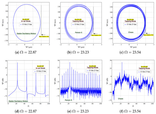
Figure 5.
The simulated FFTs and phase portraits for voltage waveform of (V) and (V) for an excitation frequency of corresponding to a single orbit oscillation, corresponding to a period-5 dynamic motion and corresponding to a full chaotic response. The FFTs of the mid-point velocity are measured in dB. The phase portraits show the threshold of the maximum allowable travel range which is limited at 2 µm.
A further increase in the excitation frequency to induces a classical impact mode, wherein the dimples engage in repeated contact with the pads while oscillating about the equilibrium position. The oscillation amplitude initially grows in a spiral trajectory until reaching the maximum stable displacement, after which the dynamics are changed due to physical contact interactions. This leads to a complex dynamic regime characterized by chaotic behavior. At this frequency, the beam exhibits a period-5 oscillation, as evidenced by the five distinct loops in the phase portrait, as shown in Figure 5b.
The corresponding Fast Fourier Transform (FFT) spectrum illustrated in Figure 5e further confirms this behavior, with an elevated noise floor providing additional evidence of chaotic dynamics. Furthermore, as the excitation frequency increases to , the system losses stability. At this point, the dynamic response no longer forms a closed orbit, as the oscillations intermittently impact the contact pads without converging to a stable trajectory. This behavior confirms a fully chaotic regime, as evidenced by the phase portraits in Figure 5c. Further validation is provided by the corresponding Fast Fourier Transform (FFT) spectrum, which exhibits a dominant peak at the excitation frequency accompanied by a pronounced elevation in the noise floor as shown in Figure 5f.
The dynamic response of the beam undergoes a significant change when the time-harmonic voltage reaches 3 (V). The bifurcation diagram reveals that the unstable regime expands considerably compared to lower AC voltage conditions, as demonstrated in Figure 6a for the dimple-free configuration. This behavior is anticipated since the increased forcing amplitude magnifies the dynamic motion which could lead to the interaction between the beam and stationary electrode. In contrast, the presence of dimples constrains the oscillation amplitude, confining the beam’s motion to a predetermined range that prevents direct contact with the electrode, as illustrated in Figure 6b. This design feature effectively mitigates stiction and dielectric charging phenomena. The system exhibits distinct dynamic regimes as the dimples engage with the contact pads, including period-4 (P-4) and period-3 (P-3) orbits, respectively. Notably, the contact zone under this excitation voltage exhibits a wider band compared to the lower voltage conditions, as clearly demonstrated by the frequency response characteristics in Figure 3.
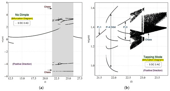
Figure 6.
The bifurcation diagram constructed for an excitation waveform of (V) and (V). It was generated using a one-sided Poincaré section, plotting the displacement v at instances where the velocity crosses zero with a positive slope. This analysis was performed near the fundamental frequency for two specific cases: (a) without dimples and (b) with dimples.
The beam was subsequently excited at discrete frequencies selected within each dynamic regime. A period-4 orbit was observed when the excitation frequency was set to , as shown in Figure 7a. This regime is characterized by significant impacts between the dimples and contact pad. The corresponding Fast Fourier Transform (FFT) spectrum, presented in Figure 7d, exhibits a dominant spectral peak at the excitation frequency . However, when the frequency was increased to , the system exhibited a period-3 oscillation pattern. The phase space trajectory demonstrates two complete non-impacting cycles followed by a third cycle involving a direct contact with the pads, which leads to a measurable increase in the noise floor of the FFT spectrum and indicates a significant increase in the energy dissipation during impact events; see Figure 7e. Finally, as the frequency reached , the system transitioned to fully chaotic behavior. In this state, the beam fails to establish a stable closed orbit, as evidenced by the phase portrait in Figure 7c. The corresponding FFT spectrum, Figure 7f, confirms this chaotic response through its characteristic broadband frequency content.
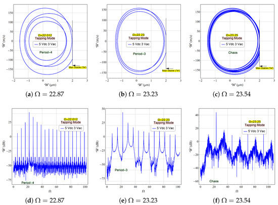
Figure 7.
The simulated FFTs and phase portraits for voltage waveform of (V) and (V) for an excitation frequency of corresponding to a period-4 orbit oscillation, corresponding to a period-3 dynamic motion and corresponding to a full chaotic response. The FFTs of the mid-point velocity are measured in the dB scale. The phase portraits show the threshold of the maximum allowable travel range which is limited at 2 µm.
A third case study was conducted, considering a higher voltage waveform. In this scenario, the DC voltage remains consistent with the previous two studies, while the AC voltage is increased to 4 (V). This configuration generates a stronger electrostatic field, which significantly influences the beam’s stiffness. As illustrated in Figure 3, the dynamic response under this excitation voltage exhibits pronounced nonlinear behavior, characterized by a hardening effect. Furthermore, the resulting impact event covers a broader range compared to lower actuation levels, suggesting the potential activation of rich nonlinear dynamic phenomena.
In the absence of dimples, the chaotic regime is significantly broader than those observed in Figure 4 and Figure 6, as demonstrated in Figure 8. This behavior is anticipated and attributed to the strength of the electrostatic force. Notably, a super-harmonic resonance emerges, followed by a period-3 orbit, before the system reverts to single-period oscillations. Subsequently, the beam undergoes collapse and loses stability upon contact with the substrate. A stable period-1 oscillation persists initially, followed by an extended regime of period-3 motion. As the frequency further increases, a chaotic attractor emerges, signifying that the dimples have come into contact with the pads.
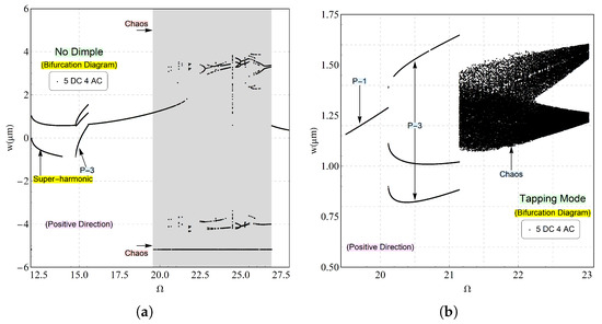
Figure 8.
The bifurcation diagram constructed for an excitation waveform of (V) and (V). It was generated using a one-sided Poincaré section, plotting the displacement v at instances where the velocity crosses zero with a positive slope. This analysis was performed near the fundamental frequency for two specific cases: (a) without dimples and (b) with dimples.
The beam was excited at discrete frequencies selected within each dynamic regime. A period-1 orbit was observed at an excitation frequency of , as depicted in Figure 9a. This regime indicates the absence of impact events. The corresponding Fast Fourier Transform (FFT) spectrum, presented in Figure 9d, displays a dominant peak at the excitation frequency along with harmonic peaks at integer multiples.
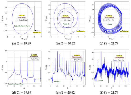
Figure 9.
The simulated FFTs and phase portraits for voltage waveform of (V) and (V) for an excitation frequency of corresponding to a period-4 orbit oscillation, corresponding to a period-3 dynamic motion and corresponding to a full chaotic response. The FFTs of the mid-point velocity are measured in the dB scale. The phase portraits show the threshold of the maximum allowable travel range which is limited at 2 µm.
Exciting the beam with a frequency located inside the period-3 regime, e.g., , the system exhibited period-3 oscillations accompanied by impact events, as illustrated in Figure 9b for the phase portrait and Figure 9e for the FFT spectrum. It is worth noting that, while the noise floor becomes elevated in this regime, it does not attain fully chaotic characteristics. Conversely, at , the system undergoes loss of stability due to direct contact between the dimples and landing pads, Figure 9c. The associated FFT spectrum, shown in Figure 9f, confirms the chaotic nature of the response through its broadband frequency content.
4. Conclusions
This study examines the dynamic response of an electrostatically actuated, double-clamped microbeam incorporating integrated contact pads and dimple structures. Although dimples serve to augment the beam’s travel range, their interaction with the underlying landing pads can precipitate an impact regime, giving rise to complex nonlinear dynamic phenomena. A reduced-order model was formulated to numerically solve the governing equation of motion. The microbeam’s response, both with and without dimples, was subsequently analyzed through the application of various analytical techniques, including bifurcation analysis and discrete excitation procedures proximal to the impacting regime. The findings indicate that the inclusion of dimples is effective in preventing stiction, pull-in instability, and the emergence of multi-valued responses. Furthermore, upon contact with the landing pads, the system exhibits pronounced nonlinear dynamics, manifesting as period-3, period-4, and period-5 oscillations, in addition to chaotic attractors. This phenomenon specifically demonstrates the potential for leveraging the dynamic transition from steady-state to chaotic regimes in the development of novel MEMS-based sensor by tracking the change in the FFTs or phase portraits, which in fact could lead to a high sensitive devices; this topic requires further investigation.
Funding
The author gratefully acknowledge the funding of the Deanship of Graduate Studies and Scientific Research, Jazan University, Saudi Arabia, through the following project number: (JU-20250271-DGSSR-RP-2025).
Data Availability Statement
The original contributions presented in this study are included in the article. Further inquiries can be directed to the corresponding author.
Acknowledgments
The author gratefully acknowledge the funding of the Deanship of Graduate Studies and Scientific Research, Jazan University, Saudi Arabia, through the following project number: (JU-20250271-DGSSR-RP-2025).
Conflicts of Interest
The author declare no conflict of interest.
References
- Maluf, N.; Williams, K. An Introduction to Microelectromechanical Systems Engineering; Artech House: Norwood, MA, USA, 2004. [Google Scholar]
- Madou, M.J. MEMS fabrication. In The MEMS Handbook; CRC: Boca Raton, FL, USA, 2002; Volume 16, pp. 1–183. [Google Scholar]
- Abdelbari, S.; Attia, A.; Bourada, F.; Bousahla, A.; Tounsi, A.; Ghazwani, M. Investigation of Dynamic Characteristics of Imperfect FG Beams on the Winkler–Pasternak Foundation under Thermal Loading. Phys. Mesomech. 2023, 26, 557–572. [Google Scholar] [CrossRef]
- Judy, J.W. Microelectromechanical systems (MEMS): Fabrication, design and applications. Smart Mater. Struct. 2001, 10, 1115. [Google Scholar] [CrossRef]
- Youzera, H.; Selim Saleh, M.M.; Ghazwani, M.H.; Meftah, S.A.; Tounsi, A.; Cuong-Le, T. Nonlinear damping and forced vibration analysis of sandwich functionally graded material beams with composite viscoelastic core layer. Mech. Based Des. Struct. Mach. 2023, 52, 4191–4210. [Google Scholar] [CrossRef]
- Fedder, G.K. MEMS fabrication. In Proceedings of the International Test Conference 2003 Proceedings ITC 2003, Charlotte, NC, USA, 30 September–2 October 2003; IEEE: Piscataway, NJ, USA, 2003; p. 691. [Google Scholar]
- Nguyen, N.T.; Huang, X.; Chuan, T.K. MEMS-micropumps: A review. J. Fluids Eng. 2002, 124, 384–392. [Google Scholar] [CrossRef]
- Nayfeh, A.H.; Younis, M.I. Dynamics of MEMS resonators under superharmonic and subharmonic excitations. J. Micromech. Microeng. 2005, 15, 1840. [Google Scholar] [CrossRef]
- Liu, X.; Fang, B.; Wan, S.; Li, X. Subharmonic resonance analysis of asymmetrical stiffness nonlinear systems with time delay. Appl. Math. Mech. 2025, 46, 1347–1364. [Google Scholar] [CrossRef]
- Ilyas, S.; Alfosail, F.K.; Bellaredj, M.L.; Younis, M.I. On the response of MEMS resonators under generic electrostatic loadings: Experiments and applications. Nonlinear Dyn. 2019, 95, 2263–2274. [Google Scholar] [CrossRef]
- Zhang, W.; Yang, D.; Guo, X. Low-frequency vibration suppression of meta-beam with softening nonlinearity. Appl. Math. Mech. 2025, 46, 1011–1028. [Google Scholar] [CrossRef]
- Shea, H.R.; Gasparyan, A.; Chan, H.B.; Arney, S.; Frahm, R.E.; López, D.; Jin, S.; McConnell, R.P. Effects of electrical leakage currents on MEMS reliability and performance. IEEE Trans. Device Mater. Reliab. 2004, 4, 198–207. [Google Scholar] [CrossRef]
- Maboudian, R. Antistiction coatings for surface micromachines. In Proceedings of the Micromachining and Microfabrication Process Technology IV, Santa Clara, CA, USA, 20–24 September 1998; SPIE: Bellingham, WA, USA, 1998; Volume 3511, pp. 108–113. [Google Scholar]
- Nishijima, N.; Hung, J.J.; Rebeiz, G.M. Parallel-contact metal-contact RF-MEMS switches for high power applications. In Proceedings of the 17th IEEE International Conference on Micro Electro Mechanical Systems, Maastricht MEMS 2004 Technical Digest, Maastricht, The Netherlands, 25–29 January 2004; IEEE: Piscataway, NJ, USA, 2004; pp. 781–784. [Google Scholar]
- He, S.; Mrad, R.B.; Chong, J. Repulsive-force out-of-plane large stroke translation micro electrostatic actuator. J. Micromech. Microeng. 2011, 21, 075002. [Google Scholar] [CrossRef]
- Chan, E.K.; Dutton, R.W. Electrostatic micromechanical actuator with extended range of travel. J. Micromech. Syst. 2000, 9, 321–328. [Google Scholar] [CrossRef]
- Alneamy, A.M. Symmetry breaking in an initially arch micro-resonator excited by a skewed electrostatic field. Microsyst. Technol. 2025, 31, 2517–2527. [Google Scholar] [CrossRef]
- Zhao, X.; Reddy, C.; Nayfeh, A. Nonlinear dynamics of an electrically driven impact microactuator. Nonlinear Dyn. 2005, 40, 227–239. [Google Scholar] [CrossRef]
- Alneamy, A.; Al-Ghamdi, M.; Park, S.; Khater, M.; Abdel-Rahman, E.; Heppler, G. Dimpled electrostatic MEMS actuators. J. Appl. Phys. 2019, 125, 024304. [Google Scholar] [CrossRef]
- Luo, A.C.; Wang, F.Y. Chaotic motion in a micro-electro–mechanical system with non-linearity from capacitors. Commun. Nonlinear Sci. Numer. Simul. 2002, 7, 31–49. [Google Scholar] [CrossRef]
- Chavarette, F.R.; Balthazar, J.M.; Felix, J.L.; Rafikov, M. A reducing of a chaotic movement to a periodic orbit, of a micro-electro-mechanical system, by using an optimal linear control design. Commun. Nonlinear Sci. Numer. Simul. 2009, 14, 1844–1853. [Google Scholar] [CrossRef]
- Gusso, A.; Viana, R.L.; Mathias, A.C.; Caldas, I.L. Nonlinear dynamics and chaos in micro/nanoelectromechanical beam resonators actuated by two-sided electrodes. Chaos Solitons Fractals 2019, 122, 6–16. [Google Scholar] [CrossRef]
- DeMartini, B.E.; Butterfield, H.E.; Moehlis, J.; Turner, K.L. Chaos for a microelectromechanical oscillator governed by the nonlinear Mathieu equation. J. Microelectromech. Syst. 2007, 16, 1314–1323. [Google Scholar] [CrossRef]
- Tajaddodianfar, F.; Pishkenari, H.N.; Yazdi, M.R.H. Prediction of chaos in electrostatically actuated arch micro-nano resonators: Analytical approach. Commun. Nonlinear Sci. Numer. Simul. 2016, 30, 182–195. [Google Scholar] [CrossRef]
- Alghamdi, M.S.; Khater, M.E.; Arabi, M.; Abdel-Rahman, E.M. Dynamics of large oscillations in electrostatic MEMS. Phys. Rep. 2024, 1094, 1–36. [Google Scholar] [CrossRef]
- Jamitzky, F.; Stark, R.W. Intermittency in amplitude modulated dynamic atomic force microscopy. Ultramicroscopy 2010, 110, 618–621. [Google Scholar] [CrossRef] [PubMed]
- Jamitzky, F.; Stark, M.; Bunk, W.; Heckl, W.M.; Stark, R.W. Chaos in dynamic atomic force microscopy. Nanotechnology 2006, 17, S213. [Google Scholar] [CrossRef] [PubMed][Green Version]
- Freire, E.; Rodriguez-Luis, A.; Gamero, E.; Ponce, E. A case study for homoclinic chaos in an autonomous electronic circuit: A trip from Takens-Bogdanov to Hopf-Šil’nikov. Phys. D Nonlinear Phenom. 1993, 62, 230–253. [Google Scholar] [CrossRef]
- Luo, A.C.; Wang, F.Y. Nonlinear dynamics of a micro-electro-mechanical system with time-varying capacitors. J. Vib. Acoust. 2004, 126, 77–83. [Google Scholar] [CrossRef]
- Lee, Y.K.; Deval, J.; Tabeling, P.; Ho, C.M. Chaotic mixing in electrokinetically and pressure driven micro flows. In Proceedings of the Technical Digest. MEMS 2001. 14th IEEE International Conference on Micro Electro Mechanical Systems (Cat. No. 01CH37090), Interlaken, Switzerland, 25 January 2001; IEEE: Piscataway, NJ, USA, 2001; pp. 483–486. [Google Scholar]
- Haghighi, H.S.; Markazi, A.H. Chaos prediction and control in MEMS resonators. Commun. Nonlinear Sci. Numer. Simul. 2010, 15, 3091–3099. [Google Scholar] [CrossRef]
- Siewe, M.S.; Hegazy, U.H. Homoclinic bifurcation and chaos control in MEMS resonators. Appl. Math. Model. 2011, 35, 5533–5552. [Google Scholar] [CrossRef]
- Peng, M. Symmetry breaking, bifurcations, periodicity and chaos in the Euler method for a class of delay differential equations. Chaos Solitons Fractals 2005, 24, 1287–1297. [Google Scholar] [CrossRef]
- Stark, R.W.; Heckl, W.M. Fourier transformed atomic force microscopy: Tapping mode atomic force microscopy beyond the Hookian approximation. Surf. Sci. 2000, 457, 219–228. [Google Scholar] [CrossRef]
- De, S.K.; Aluru, N.R. Complex Oscillations and Chaos in Electrostatic Microelectromechanical Systems under Superharmonic Excitations. Phys. Rev. Lett. 2005, 94, 204101. [Google Scholar] [CrossRef]
- Gusso, A.; Viana, R.L.; Ujevic, S. Enhanced complexity of chaos in micro/nanoelectromechanical beam resonators under two-frequency excitation. Commun. Nonlinear Sci. Numer. Simul. 2022, 114, 106683. [Google Scholar] [CrossRef]
- Alemansour, H.; Miandoab, E.M.; Pishkenari, H.N. Effect of size on the chaotic behavior of nano resonators. Commun. Nonlinear Sci. Numer. Simul. 2017, 44, 495–505. [Google Scholar] [CrossRef]
- Barceló, J.; Rosselló, J.; Bota, S.; Segura, J.; Verd, J. Electrostatically actuated microbeam resonators as chaotic signal generators: A practical perspective. Commun. Nonlinear Sci. Numer. Simul. 2016, 30, 316–327. [Google Scholar] [CrossRef]
- Zhang, W.M.; Tabata, O.; Tsuchiya, T.; Meng, G. Noise-induced chaos in the electrostatically actuated MEMS resonators. Phys. Lett. A 2011, 375, 2903–2910. [Google Scholar] [CrossRef]
- Polo, M.F.P.; Molina, M.P.; Chica, J.G. Chaotic dynamic and control for micro-electro-mechanical systems of massive storage with harmonic base excitation. Chaos Solitons Fractals 2009, 39, 1356–1370. [Google Scholar] [CrossRef]
- Ebrahimi, R. Chaos in coupled lateral-longitudinal vibration of electrostatically actuated microresonators. Chaos Solitons Fractals 2022, 156, 111828. [Google Scholar] [CrossRef]
- Tajaddodianfar, F.; Hairi Yazdi, M.R.; Pishkenari, H.N. On the chaotic vibrations of electrostatically actuated arch micro/nano resonators: A parametric study. Int. J. Bifurc. Chaos 2015, 25, 1550106. [Google Scholar] [CrossRef]
- Alneamy, A.M. Dynamic snap-through motion and chaotic attractor of electrostatic shallow arch micro-beams. Chaos Solitons Fractals 2024, 182, 114777. [Google Scholar] [CrossRef]
- Nayfeh, A.H.; Younis, M.I.; Abdel-Rahman, E.M. Reduced-order models for MEMS applications. Nonlinear Dyn. 2005, 41, 211–236. [Google Scholar] [CrossRef]
Disclaimer/Publisher’s Note: The statements, opinions and data contained in all publications are solely those of the individual author(s) and contributor(s) and not of MDPI and/or the editor(s). MDPI and/or the editor(s) disclaim responsibility for any injury to people or property resulting from any ideas, methods, instructions or products referred to in the content. |
© 2025 by the author. Licensee MDPI, Basel, Switzerland. This article is an open access article distributed under the terms and conditions of the Creative Commons Attribution (CC BY) license (https://creativecommons.org/licenses/by/4.0/).