Article

Design of Extended Dissipative Approach via Memory Sampled-Data Control for Stabilization and Its Application to Mixed Traffic System

by
Wimonnat Sukpol
1,
Vadivel Rajarathinam
1,*,
Porpattama Hammachukiattikul
1 and
Putsadee Pornphol
2
1
Department of Mathematics, Faculty of Science and Technology, Phuket Rajabhat University, Phuket 83000, Thailand
2
Department of Digital Technology, Faculty of Science and Technology, Phuket Rajabhat University, Phuket 83000, Thailand
*
Author to whom correspondence should be addressed.
Mathematics 2025, 13(15), 2449; https://doi.org/10.3390/math13152449 (registering DOI)
Submission received: 13 June 2025 / Revised: 24 July 2025 / Accepted: 25 July 2025 / Published: 29 July 2025
(This article belongs to the Special Issue Modeling, Control, and Optimization for Transportation Systems)

Abstract

This study examines the extended dissipativity analysis for newly designed mixed traffic systems (MTSs) utilizing the coupling memory sampled-data control (CMSDC) approach. The traffic flow creates a platoon, and the behavior of human-driven vehicles (HDVs) is presumed to adhere to the optimal velocity model, with the acceleration of a single-linked automated vehicle regulated directly by a suggested CMSDC. The ultimate objective of this work is to present a CMSDC approach for optimizing traffic flow amidst disruptions. The primary emphasis is on the proper design of the CMSDC to ensure that the closed-loop MTS is extended dissipative and quadratically stable. A more generalized CMSDC methodology incorporating a time delay effect is created using a Bernoulli-distributed sequence. The existing Lyapunov–Krasovskii functional (LKF) and enhanced integral inequality methods offer sufficient conditions for the suggested system to achieve an extended dissipative performance index. The suggested criteria provide a comprehensive dissipative study, evaluating L 2 L , H , passivity, and dissipativity performance. A simulation example illustrates the accuracy and superiority of the proposed controller architecture for the MTS.

1. Introduction

Because sensors, actuators, and computers are all linked by a communication network, networked control systems are very useful in robotics, automotive systems, and process control. This is because they make maintenance and debugging more flexible. A considerable revolution in transportation systems has occurred in recent decades as a result of breakthroughs in automation, which include the development of infrastructure and vehicles that are capable of driving themselves. In the process of transitioning from human-driven vehicles (HDVs) to fully connected and automated vehicles (CAVs), new challenges arise, which in turn encourage research on mixed traffic systems (MTSs) that include both HDVs and CAVs (for example, [1,2,3] and references). The rapid growth of automation has resulted in substantial changes to transportation systems, particularly with the rise of intelligent infrastructures and autonomous cars. These changes have been brought about by the rapid development of automation. The study of mixed traffic scenarios, in which both types of vehicles coexist, is of utmost importance due to the ongoing challenges that have arisen as a result of the transition from conventional HDVs to fully CAVs [4,5,6]. This move presents opportunities to take advantage of the capabilities of CAVs to enhance traffic management, decrease congestion, and contribute to an overall improvement in the efficiency and safety of transportation.
Since the beginning of time, the regulation of traffic flow has been accomplished through the utilization of fixed-location actuators, such as ramp metering (RMs) and variable speed limits (VSLs). In spite of the fact that they are successful, these systems usually have restricted flexibility and substantial expenses associated with their implementation. CAVs, on the other hand, provide a dynamic and cost-effective alternative by functioning as mobile actuators, which are also sometimes referred to as Lagrangian actuators [7,8,9]. This brings in more adaptability and responsiveness in traffic management. When all of the vehicles in the system are automated, advanced control methods such as cooperative adaptive cruise control (CACC) and adaptive cruise control (ACC) can be utilized to enhance the performance of the system and optimize the flow of traffic. Authors of the study [10] investigated the timing of traffic lights for mixed-flow networks that include pedestrians and vehicles. To be more specific, ref. [11] conducted research on the optimization model and traffic light control technique for heterogeneous traffic distribution systems. The topic of mixed-agent cooperative reinforcement learning for traffic light management has been investigated recently in a publication.
On the other hand, the traffic light model has been modified to incorporate a substantial number of other strategies (see Table 1). The concept of the extended dissipative performance index, which is both innovative and effective, was initially proposed in [12]. Since then, an increasing number of researchers have been working towards the application of this system performance index in order to evaluate and investigate both continuous- and discrete-time systems utilizing control strategies [13,14,15,16]. For instance, the convex incremental dissipativity analysis of nonlinear systems has been the subject of research. A study was conducted in [14] to investigate the quantized sampled-data control for extended dissipative analysis of the T–S fuzzy system. Recently, in [17], extended dissipative analysis and taxiing control of fuzzy-model-based aircraft-on-ground systems were investigated. Extended dissipativity may be transformed into common performance indices by modifying the weighting matrix in performance measures. These indices include L 2 L , H , passivity, and the dissipativity attribute [12,18]. Recently, extended dissipativity-based performance analysis has become a popular methodology for assessing dynamic system resilience, safety, and energy-like qualities. This architecture is especially useful in MTSs with CAVs and HDVs. It lets you study how the CAV regulates HDV interactions under shocks, delays, and nonlinearities. Control techniques may be designed to maintain smooth velocity tracking, inter-vehicle spacing, and string stability while accounting for uncertainties and various driver behaviors by modifying dissipativity indices, such as L 2 L , H , passivity, and ( Q , S , R ) . As a result, this is one of the primary objectives of this paper.
Multiple investigations in the literature create an appropriate control mechanism for an MTS [1,4,6]. The purpose of these studies is to improve the performance of the system at the system level, stabilize the flow of traffic, and eliminate disruptions that are not acceptable. Therefore, it is possible that the control methods that were outlined before have an effect on the nearest point stability of the traffic system. This is because these control schemes were developed expressly for the equilibrium condition. In the field of continuous-time system research, sampled-data control (SDC) has become a popular topic because of the several advantages it offers, including fast speed, high efficiency, and high dependability. Remarkable results have been reported up to this point in the works of [14,19,20], for example. Among the many SDC approaches, general dissipative control was investigated, and the linked memory sampled-data control (MSDC) was developed in the study cited in [21,22]. As a matter of fact, numerical control programming has consistently utilized the sample interval throughout its history. Because of the presence of external disturbances and the varied computational outputs that are produced by the constant sample duration, the application breadth is severely restricted. On the other hand, to the best of our knowledge, the issue of extended dissipative analysis for MTSs in comparison to MSDC has not been investigated.
In light of the above discussion, we consider the MTS and study the extended dissipative via the MSDC strategy. Compared with existing results (see Table 2), several contributions to our work are highlighted as follows:
(1)
According to the existing literature, the MSDC strategy is considered for the first time in the extended dissipative framework to examine the controllability and stabilization of an MTS with a single CAV and multiple heterogeneous HDVs.
(2)
We deal with the suggested integral terms by using the appropriate LKF and other inequality procedures, which results in the quadratically stable and extended dissipative condition.
(3)
The suggested MTS necessary condition, which makes the system more generic, was determined using the extended dissipative performance index framework, which includes L 2 L , H , passivity, and ( Q , S , R ) dissipativity, which makes the system more general.
Table 1. Comparison of key features in traffic system models.
Aspect[1][2][3][7][8][9]Our Paper
Sampled-data control
Extended dissipative
Traffic model
LMI method
Table 2. Summary of relevant research works.
ReferenceMain ContributionRelevance to Current Work
[23]Studied robust H stabilization for T-S fuzzy systems with time-varying delays and MSDC.Our work applies these to an MTS, emphasizing comprehensive extended dissipativity.
[24]Investigated nonfragile exponential synchronization of delayed complex dynamical networks with MSDC.Our work focuses on extended dissipativity stabilization for an MTS, a distinct control objective and practical application domain.
[25]Analyzed nonfragile consensus of multi-agent systems based on MSDC.Our focus is extended dissipativity stabilization for specific MTS platoons and traffic flow optimization, a different problem.
[22]Presented further results on stabilization of chaotic systems based on fuzzy MSDC.Our paper applies MSDC (without fuzzy logic) to stabilize a practical MTS.
[26]Conducted dissipativity analysis for T–S fuzzy systems under MSDC.Our work extends this to extended dissipativity for an MTS, offering a comprehensive performance evaluation.
[27]Explored finite-time stabilization of T–S fuzzy semi-Markov switching systems via coupling memory sampled-data control (CMSDC).Our paper employs CMSDC for extended dissipativity and quadratic stability of an MTS, a different objective and application.

2. Problem Formulation and Preliminaries

Consider the following system:
x ˙ ( t ) = A x ( t ) + B η x ( t τ ) + C u ( t ) + D w ( t ) , y ( t ) = E x ( t ) .
Let x ( t ) = [ x 1 T , x 2 T , , x n T ] T R 2 n 1 represent the system-state vector and define the control input as u ( t ) R . The system is subject to a constant delay τ . The system output is denoted by y ( t ) , while w ( t ) corresponds to an external disturbance, which belongs to L 2 [ 0 , ) . The matrices A , B η , C , D , and E are known and have suitable dimensions to conform to the system structure.

Design of Coupling Memory Sampled-Data Control (CMSDC)

The control input is applied via a zero-order hold (ZOH) mechanism to enable the development of the SDC strategy. The series of holding instants is represented as 0 < t 0 < t 1 < < t k < , with the condition that lim k t k = + . In accordance with this sequence, the control signal u ( t ) is defined within the framework of CMSDC as follows:
u ( t ) = α ( t ) K 1 x ( t k κ ) + ( 1 α ( t ) ) K 2 x ( t k ) , t [ t k , t k + 1 )
In this context, x ( t k ) signifies the system state x ( t ) that has been sampled at the specific sampling instant t k , while κ indicates a constant delay, and K 1 and K 2 are the sampled-data feedback control gain matrices with appropriate dimensions. The sampling intervals are specified as σ k = t k + 1 t k , with the condition that 0 < σ k σ , where σ > 0 represents a known upper limit applicable for all k 0 . The sampling instant t k is defined as t k = t σ ( t ) , where σ ( t ) = t t k adheres to the constraints 0 σ ( t ) σ and maintains the condition σ ˙ ( t ) = 1 for t t k . Additionally, α ( t ) is defined as a time-dependent stochastic function that delineates the relationship between the mode-switching sampled-data control framework and traditional sampled-data proportional control.
α ( t ) = 1 Signal was sent and received without any issues 0 else ,
where α ( t ) is a white sequence following a Bernoulli distribution with P r { α ( t ) = 1 } = ξ { α ( t ) } = α , and P r { α ( t ) = 0 } = 1 ξ { α ( t ) } = 1 α . Then,
u ( t ) = α ( t ) K 1 x ( t σ ( t ) κ ) + ( 1 α ( t ) ) K 2 x ( t σ ( t ) ) .
Combining (1) and (3), we get
x ˙ ( t ) = A x ( t ) + B η x ( t τ ) + C ( α ( t ) K 1 x ( t σ ( t ) κ ) + ( 1 α ( t ) ) K 2 x ( t σ ( t ) ) ) + D w ( t ) , y ( t ) = E x ( t ) .
Assumption 1. 
For given matrices ψ 1 , ψ 2 , ψ 3 , and ψ 4 , satisfy the following conditions:
  • ψ 1 = ψ 1 T 0 , ψ 3 = ψ 3 T > 0 , ψ 4 = ψ 4 T 0 .
  • ( ψ 1 + ψ 2 ) ψ 4 = 0 .
Definition 1
([28]). Consider the matrices ψ 1 , ψ 2 , ψ 3 , and ψ 4 in accordance with Assumption 1. The system described in Equation (4) is classified as extended dissipative if there exists a scalar ς ^ > 0 such that, for all instances where t f 0 , the subsequent inequality is satisfied:
0 t f J ( t ) d t sup 0 t t f y T ( t ) ψ 4 y ( t ) + ς ^ ,
where J ( t ) = y T ( t ) ψ 1 y ( t ) + 2 y T ( t ) ψ 2 w ( t ) + w T ( t ) ψ 3 w ( t ) .
Definition 2 
([28]). Consider system (4). If there exists a positive scalar υ > 0 such that the time derivative of the Lyapunov function satisfies the inequality
V ˙ ( t ) υ x ( t ) 2 ,
where x ( t ) 2 = x T ( t ) x ( t ) , then the system (4) with w ( t ) = 0 is said to exhibit quadratic stability.

3. Main Results

Here, we examine the extended dissipative analysis using the coupling MSDC methodology. An appropriate LKF will be selected, and adequate circumstances will be configured. We will start by addressing a few important indications.
1 ( t ) = [ x T ( t ) x T ( t k ) t k t x T ( s ) d s ] , 2 ( t ) = [ x T ( t k ) x T ( t k + 1 ) ] , 3 ( t ) = [ x T ( t ) x T ( t k + 1 ) t t k + 1 x T ( s ) d s ] , 4 ( t ) = [ x ˙ T ( t ) x T ( t ) ] , 5 ( t ) = [ x ˙ T ( t ) x T ( t ) ] , ψ ( s ) = x ( s ) x ( t σ ( t ) κ ) .
Theorem 1.
For a given scalar κ > 0 , σ > 0 , α > 0 , τ ; matrices ψ 1 , ψ 2 , ψ 2 , ψ 4 satisfying Assumption 1; and gains K 1 , K 2 , the system (4) is quadratically stable and extended dissipative if there exist symmetric positive-definite matrices P 1 , P 2 , S , Q 1 , Q 2 , Q 3 , Q 4 , T 1 , T 2 , V , any matrices G i , ( i = 1 , 2 , 3 ) , U 1 , and the subsequent inequalities are satisfied
T 2 U 1 T 2 0 ,
P 1 E T ψ 4 E 0 ,
Φ 12 × 12 < 0 ,
where
Φ = 2 I 1 T P 1 I 3 + I 1 T P 2 I 1 I 2 T P 2 I 2 + τ I 3 T S I 3 ( I 1 T I 2 T ) S ( I 1 I 2 ) [ I 1 T I 4 T I 10 T ] Q 1 [ I 1 I 4 I 10 ] 2 [ I 1 T I 4 T I 10 T ] Q 2 [ I 4 I 11 ] 2 σ [ [ I 1 T I 4 T I 10 T ] Q 1 [ I 3 I 1 ] 2 σ [ I 3 T I 1 T ] Q 2 [ I 4 I 11 ] [ [ I 1 T I 11 T I 12 T ] ( Q 3 [ I 1 I 11 I 12 ] + 2 Q 4 [ I 4 I 11 ] ) 2 σ [ [ I 1 T I 11 T I 12 T ] Q 3 [ I 3 I 1 ] + [ I 3 T I 1 T ] Q 4 [ I 4 I 11 ] ] + I 1 T T 1 I 1 I 2 T T 1 I 2 + σ 2 I 3 T T 2 I 3 ( I 1 T I 5 T ) T 2 ( I 1 I 5 ) ( I 1 T I 5 T ) U 1 ( I 5 I 6 ) ( I 5 T I 6 T ) T 2 ( I 5 I 6 ) + σ 2 I 3 T V I 3 π 2 4 ( I 8 T I 7 T ) V ( I 8 I 7 ) I 1 T E T ψ 1 E I 1 I 1 T E T ψ 2 I 9 I 9 T ψ 3 I 9 + s y m { Φ 1 T Φ 0 } , Φ 1 = [ G 1 T 0 G 3 T 0 0 0 G 2 T 0 0 0 5 t i m e s ] , Φ 0 = [ A B η I 0 C α K 2 0 C ( 1 α ) K 1 0 D 0 0 0 ] , I s = [ 0 n × ( s 1 ) n I n 0 n × ( 12 s ) n ] T , s = 1 , 2 , . . . , 12 .
Proof. 
Consider the following LKF is given as
V ( t ) = V 1 ( t ) + V 2 ( t ) + V 3 ( t ) + V 4 ( t ) + V 5 ( t ) + V 6 ( t ) ,
where
V 1 ( t ) = x T ( t ) P 1 x ( t ) V 2 ( t ) = t τ t x T ( s ) P 2 x ( s ) d s + t τ t t + θ t x ˙ T ( s ) S x ˙ ( s ) d s d θ , V 3 ( t ) = ( t k + 1 t ) 1 T ( t ) [ Q 1 1 ( t ) + 2 Q 2 2 ( t ) ] , V 4 ( t ) = ( t t k ) 3 T ( t ) [ Q 3 3 ( t ) + 2 Q 4 2 ( t ) ] , V 5 ( t ) = t σ t x T ( s ) T 1 x ( s ) d s + σ σ 0 t + θ t x ˙ T ( s ) T 2 x ˙ ( s ) d s d θ ,
and V 6 ( t ) is a discontinuous functional of form
V 6 ( t ) = σ 2 t σ ( t ) k t x ˙ T ( s ) V x ˙ ( s ) d s π 2 4 t σ ( t ) k t κ ψ T ( s ) V ψ ( s ) d s .
The derivative of (10) can be computed as
V ˙ 1 ( t ) = 2 x T ( t ) P 1 x ˙ ( t ) , V ˙ 2 ( t ) = x T ( t ) P 2 x ( t ) x T ( t τ ) P 2 x ( t τ ) + τ x ˙ T ( t ) S x ˙ ( t ) t τ t x ˙ T ( s ) S x ˙ ( s ) d s , = x T ( t ) P 2 x ( t ) x T ( t τ ) P 2 x ( t τ ) + τ x ˙ T ( t ) S x ˙ ( t ) ( x ( t ) x ( t τ ) ) T S ( x ( t ) x ( t τ ) ) , V ˙ 3 ( t ) = [ 1 T ( t ) ( Q 1 1 ( t ) + 2 Q 2 2 ( t ) ) + 2 ( t k + 1 t ) [ 1 T ( t ) Q 1 4 ( t ) + 4 T ( t ) Q 2 2 ( t ) ] ] , V ˙ 4 ( t ) = [ 3 T ( t ) ( Q 3 3 ( t ) + 2 Q 4 2 ( t ) ) + 2 ( t t k ) [ 3 T ( t ) Q 3 5 ( t ) + 5 T ( t ) Q 4 2 ( t ) ] ] , V ˙ 5 ( t ) = x T ( t ) T 1 x ( t ) x T ( t σ ) T 1 x ( t σ ) + σ 2 x ˙ T ( t ) T 2 x ˙ ( t ) σ t σ t x ˙ T ( s ) T 2 x ˙ ( s ) d s .
Utilizing the Reciprocal convex technique [29] to deal with the above integral term, for matrix U 1 satisfying T 2 U 1 T 2 0 , we get
σ t σ t x ˙ T ( s ) T 2 x ˙ ( s ) d s x T ( t ) x T ( t σ ( t ) ) x T ( t σ ( t ) ) x T ( t σ ) T 2 U 1 T 2 x ( t ) x ( t σ ( t ) ) x ( t σ ( t ) ) x ( t σ ) , V ˙ 6 ( t ) = σ 2 x ˙ T ( t ) V x ˙ ( t ) π 2 4 ( x T ( t κ ) x T ( t σ ( t ) κ ) ) V ( x ( t κ ) x ( t σ ( t ) κ ) ) .
Additionally, on the basis of system (4), the requirements are true for every suitably dimensioned matrix G i ( i = 1 , 2 , 3 ) .
0 = 2 [ x T ( t ) G 1 + x T ( t σ ( t ) κ ) G 2 + x ˙ T ( t ) G 3 ] × [ x ˙ ( t ) + A x ( t ) + B η x ( t τ ) + C ( α ( t ) K 1 x ( t σ ( t ) κ ) + ( 1 α ( t ) ) K 2 x ( t σ ( t ) ) ) + D w ( t ) ] , = ξ T ( t ) s y m { Φ 1 T Φ 0 } ξ ( t ) .
Finally, from (13) to (14) and according to Definition 1 J ( t ) = y T ( t ) ψ 1 y ( t ) + 2 y T ( t ) ψ 2 w ( t ) + w T ( t ) ψ 3 w ( t ) , we can get
V ˙ ( t ) J ( t ) < ξ T ( t ) Φ ξ ( t ) < 0 .
where ξ T ( t ) = [ x T ( t ) , x T ( t τ ) , x ˙ T ( t ) , x T ( t k ) , x T ( t σ ( t ) ) , x T ( t σ ) , x T ( t σ ( t ) κ ) , x T ( t κ ) , w T ( t ) , t k t x T ( s ) d s , x ( t k + 1 ) , t t k + 1 x T ( s ) d s ] .
According to linear matrix inequality (9), it is established that Φ < 0 . Given that Φ < 0 , it follows that there exists a sufficiently small scalar υ 1 > 0 such that
Φ < υ 1 I .
Given this condition, inequality (15) can be expressed in the following manner:
V ˙ ( t ) J ( t ) υ 1 ξ ( t ) 2 υ 1 x ( t ) 2 , V ˙ ( t ) J ( t ) υ 1 x ( t ) 2 .
When considering w ( t ) = 0 , then J ( t ) = y T ( t ) ψ 1 y ( t ) . Noticing that ψ 1 0 it yields that
V ˙ ( t ) υ 1 x ( t ) 2 .
According to Definition 2, the system (4) is quadratically stable in a manner. Following this, we will go on to the extended dissipative condition for the system that is being presented here (4). Based on the definition of Φ , one can straightforwardly conclude that
V ˙ ( t ) J ( t ) 0 .
Integrating both sides of the above inequality from 0 to t gives
0 t J ( α ) d α V ( t ) V ( 0 ) x T ( t ) P 1 x ( t ) + ς ^ .
In accordance with Definition 1, it is necessary to demonstrate that the subsequent inequality is valid for all matrices ψ 1 , ψ 2 , ψ 3 , and ψ 4 that respond to Assumption 1:
0 t f J ( α ) d α sup 0 < t t f y T ( t ) ψ 4 y ( t ) 0 ,
where t f is any non-negative scalar. In order to prove inequality (5), the analysis is separated into two instances based on the norm of the vector ψ 4 . In the first case, ψ 4 = 0 , which is usually a border or trivial condition. All non-trivial occurrences are covered in the second case, when ψ 4 0 . We prove inequality (5) under all relevant conditions by carefully considering both cases.
In the first case, if ψ 4 = 0 , then (17) implies that, for any t f 0 ,
0 t f J ( α ) d α x T ( t f ) P 1 x ( t f ) + ς ^ 0 ,
which signifies that Definition 1 is true. If ψ 4 0 , we can conclude that the matrices ψ 1 = 0 , ψ 2 = 0 , and ψ 3 > 0 ; thus, for any t f t > 0 , we have
0 t f J ( α ) d α 0 t J ( α ) d α x T ( t ) P 1 x ( t ) + ς ^ .
Thus, according to (8), note the fact that
y T ( t ) ψ 4 y ( t ) = x T ( t ) E T ψ 4 E x ( t ) x T ( t ) P 1 x ( t ) 0 t f J ( α ) d α .
It is clear that, for any t 0 , t f 0 with t f t ,
0 t f J ( α ) d α y T ( t ) ψ 4 y ( t ) + ς ^ .
Because of this, inequality (5) is valid for every t f 0 . The conclusion that the suggested system (4) meets the extended dissipativity condition as described in Definition (1) may be reached by performing an analysis of both situations, specifically ψ 4   = 0 and ψ 4   0 . It may be concluded that the proof of this theorem is finished. □
Theorem 2.
For given scalars κ > 0 , σ , α > 0 , τ , w 1 , w 2 and matrices ψ 1 , ψ 2 , ψ 3 , and ψ 4 satisfying Assumption 1, the system (4) is said to be quadratically stable and extended dissipative if there exist symmetric positive-definite matrices P ˜ 1 , P ˜ 2 , S ˜ , Q ˜ 1 , Q ˜ 2 , Q ˜ 3 , Q ˜ 4 , T ˜ 1 , T ˜ 2 , and V ˜ , as well as any matrices G i ( i = 1 , 2 , 3 ) , U 1 , X ^ , and Y ^ , such that the following matrix inequalities are satisfied:
T ˜ 2 U ˜ 1 T ˜ 2 0 ,
P ˜ 1 G E T ψ 4 > 0 ,
Ξ 12 × 12 < 0 ,
where
Ξ = 2 I 1 T P ˜ 1 I 3 + I 1 T P ˜ 2 I 1 I 2 T P ˜ 2 I 2 + τ I 3 T S ˜ I 3 ( I 1 T I 2 T ) S ˜ ( I 1 I 2 ) [ I 1 T I 4 T I 10 T ] Q ˜ 1 [ I 1 I 4 I 10 ] 2 [ I 1 T I 4 T I 10 T ] Q ˜ 2 [ I 4 I 11 ] 2 σ [ [ I 1 T I 4 T I 10 T ] Q ˜ 1 [ I 3 I 1 ] 2 σ [ I 3 T I 1 T ] Q ˜ 2 [ I 4 I 11 ] [ [ I 1 T I 11 T I 12 T ] ( Q ˜ 3 [ I 1 I 11 I 12 ] + 2 Q ˜ 4 [ I 4 I 11 ] ) 2 σ [ [ I 1 T I 11 T I 12 T ] Q ˜ 3 [ I 3 I 1 ] + [ I 3 T I 1 T ] Q ˜ 4 [ I 4 I 11 ] ] + I 1 T T ˜ 1 I 1 I 2 T T ˜ 1 I 2 + σ 2 I 3 T T ˜ 2 I 3 ( I 1 T I 5 T ) T ˜ 2 ( I 1 I 5 ) ( I 1 T I 5 T ) U ˜ 1 ( I 5 I 6 ) ( I 5 T I 6 T ) T ˜ 2 ( I 5 I 6 ) + σ 2 I 3 T V ˜ I 3 π 2 4 ( I 8 T I 7 T ) V ˜ ( I 8 I 7 ) I 1 T E T ψ 1 E I 1 I 1 T E T ψ 2 I 9 I 9 T ψ 3 I 9 + s y m { Φ 1 T Φ 0 } , Φ 1 = [ I 0 w 2 I 0 0 0 w 1 I 0 0 0 5 t i m e s ] , Φ 0 = [ A G T B η G T G T 0 C α Y ^ 0 C ( 1 α ) X ^ 0 D 0 0 0 ] .
and the sampled-data control gain matrices are given by K 1 = X ^ ( G T ) 1 , K 2 = Y ^ ( G T ) 1 .
Proof. 
Define G 1 = G 1 , G 2 = w 1 G 1 , G 3 = w 2 G 1 , P ˜ 1 = G P 1 G T , P ˜ 2 = G P 2 G T , S ˜ = G S G T , Q ˜ 1 = G Q 1 G T , Q ˜ 2 = G Q 2 G T , Q ˜ 3 = G Q 3 G T , Q ˜ 4 = G Q 4 G T , T ˜ 1 = G T 1 G T , T ˜ 2 = G T 2 G T , V ˜ = G V G T , U ˜ 1 = G U 1 G T , Υ 1 = d i a g { G , G , G } , Υ 2 = d i a g { Υ 1 , Υ 1 , G , G , I , Υ 1 } , Υ 3 = d i a g { G , G } . Pre- and post-multiplying (7) with Υ 3 , (8) with G , and (9) with Υ 2 , we get (21), (22), and (23). Thus, the proof is completed. □
Remark 1.
The CAV experiences severe disruptions when in motion. A coupling MSDC is then suggested in order to improve traffic efficiency, decrease communication limitations, and smooth traffic flow. The CAV’s stability and resilience are improved by the implementation of this novel control technique.
Remark 2.
From the proposed MSDC. The switching signal  α ( t )  plays a crucial role in capturing the stochastic nature of communication in networked control systems. It is modeled as a Bernoulli-distributed random variable, where  α ( t ) = 1  indicates a successful transmission of the control signal, and  α ( t ) = 0  denotes a transmission failure. The probability of success is defined as  P r { α ( t ) = 1 } = α  and failure as  P r { α ( t ) = 0 } = 1 α . This probabilistic framework reflects real-world scenarios in which communication links are unreliable and packet dropouts may occur randomly.
The value of  α ( t )  determines which control input is activated at each sampling interval:
  • If  α ( t ) = 1 , the controller applies the delayed state x ( t σ ( t ) κ )  with gain  K 1 , assuming the signal was transmitted and received without issue.
  • If  α ( t ) = 0 , the controller instead uses the more recent state  x ( t σ ( t ) )  with gain  K 2 , compensating for the loss of the delayed signal.
This probability mechanism provides robustness by ensuring that the system continues to receive control input even when the ideal delayed signal is unavailable, thus improving reliability and stability under random communication imperfections.
Remark 3.
The MTS via coupling MSDC studied in this paper differs significantly from existing works in several aspects (see Table 1 and Table 2). How to model the MTS with one CAV and 2 HDVs with respect to dissipative performance has become one of the main themes in our research work. More particularly, some pioneering works have been conducted on MSDC. In contrast to the existing works [22,23,24,25] that extensively explore MSDC for stabilization of generic fuzzy/chaotic systems, or synchronization/consensus in general networks, our paper presents a distinct contribution. However, these studies primarily focus on theoretical control frameworks without direct consideration of realistic physical systems. In contrast, the present work introduces a novel and practical control framework for an MTS consisting of both HDVs and a CAV. By employing a coupling MSDC approach, the paper bridges the gap between theory and practice. The model incorporates optimal velocity dynamics for HDVs, Bernoulli-distributed random sampling, and extended dissipativity analysis to ensure robust performance. Additionally, the effectiveness of the proposed strategy is demonstrated through comprehensive simulations on realistic traffic scenarios, highlighting its superiority in handling features not addressed collectively in the existing literature [22,23,24,25].

4. Numerical Example

In this section, the proposed theoretical observations are confirmed to be effective and applicable by comparing the numerical simulations of the proposed model (4) with the experimental range of parameter values. A comparative example is also provided to illustrate the advantages of the proposed control method and the effectiveness of the derived sufficient conditions. This illustrates the effectiveness of the proposed control scheme, its validation procedure, and the peculiarities presented in algorithm.
Example 1.
Take into consideration the dynamics of car-following in a mixed vehicle platoon, as described by [30]. This platoon comprised one CAV and numerous HDVs. The dynamics of the platoon can be compactly expressed as follows:
x ˙ ( t ) = A x ( t ) + B η x ( t τ ) + C u ( t ) ,
Here, the aggregated vector of the states of all vehicles is x ( t ) = [ x 1 T , x 2 T , x n T ] R 2 n 1 ; u ( t ) R is defined as the control input, and w ( t ) is the disturbance, where
A = 0 0 0 0 A 21 A 2 0 0 0 A 1 A 2 0 0 0 0 A 1 A 2 , C = 1 0 0 0 , B η = 0 0 0 0 B η 21 B η 2 0 0 0 B η 1 B η 2 0 0 0 0 B η 1 B η 2 ,
with A 1 = 0 1 0 0 , A 2 = 0 1 0 0 , A 21 T = 1 0 , and
B η 21 T = 0 β 3 , B η 1 = 0 0 0 β 3 , B η 2 = 0 0 β 1 β 2 ,
where β 1 , β 2 , and β 3 are defined as
β 1 = π α v m a x S g o S s t v v m a x ( 1 v v m a x ) , β 2 = θ + α , β 3 = θ .
By using an optimal velocity model, the acceleration function H ( · ) of the i t h HDVs is written as H ( · ) = α ( V ( s i ) v i ) + θ s ˙ i , where v i , s i , s ˙ i , are the velocity, the spacing, and the relative velocity, respectively. The equilibrium velocity and the maximum allowable velocity are defined as v and v m a x . Moreover, α > 0 and θ > 0 are the sensitivity of the human drivers to compensate for the speed errors. The desired velocity V ( s ) is denoted as
V ( s ) = 0 , s s s t , h v ( s ) , s s t < s < s g o , v m a x , s > s g 0
where h v ( s ) is defined as
h v ( s ) = v m a x 2 1 c o s ( π s s s t s g 0 s s t ) .
Moreover, a mixed platoon will inevitably experience disruptions due to a variety of circumstances, such as lane changes and merges or the random behavior of HDVs [31,32]. Therefore, in the modeled system (24), disturbance signal w ( t ) is applied to each vehicle’s acceleration.
x ˙ ( t ) = A x ( t ) + B η x ( t τ ) + C u ( t ) + D w ( t ) , y ( t ) = E x ( t ) .
In this manner, y ( t ) is noted as the output vector. Define D = d i a g [ g d 1 , g d , , g d ] R 2 n 1 with g d = [ 0 1 ] T and g d 1 = 1 and also E = [ e ( 2 s 1 1 ) e ( 2 s 1 ) e ( 2 s m 1 ) e ( 2 s m ) ] . Note that we can have s m = 1 , since the CAV has access to its own information.
Since considering the mixed platoon of 3 vehicles (1 CAV and 2 HDVs), where A , B η are the matrices with 5 × 5 , the relevant input values are given in (24), and the matrix input values of C are defined in (24). The D and E are the known matrices associated with the dimension matrices in (25).
The following Table 3 shows the parameter values of the provided system (25).
Further, we provide the following algorithm to calculate the maximum upper bound of the sample period σ. This algorithm utilizes the MATLAB LMI toolbox to solve the LMIs (21)–(23) in Theorem 2.
Algorithm to calculate the maximum upper bound of the sampling period σ
1. 
Define System Parameters: Initialize the required system matrices including A , B η , C , D , and E with appropriate dimensions and the known parameters.
2. 
Define Control Gains: Introduce K 1 and K 2 for the controller gains and set up the unknown matrices P ˜ 1 , P ˜ 2 , S ˜ , Q ˜ 1 , Q ˜ 2 , Q ˜ 3 , Q ˜ 4 , T ˜ 1 , T ˜ 2 , and V ˜ .
3. 
Set Performance Matrices: Configure the weighting matrices for different performance indices (e.g., L 2 L , H , passivity, and ( Q , S , R ) -Dissipativity).
4. 
Formulate LMI Constraints:
  • Ensure positive definiteness of Lyapunov matrices.
  • Incorporate stability conditions using system dynamics.
  • Include delay-dependent terms for robustness.
5. 
Define Optimization Objective: Maximize the sampling period σ while maintaining feasibility.
6. 
Solve the LMI Problem: Use an LMI solver in MATLAB to check feasibility and determine optimal parameters.
min σ subject to LMIs hold for system stability
7. 
Check Results: If a feasible solution exists, extract the maximum sampling period and controller gains; otherwise, Return to step 1 and adjust the sampling intervals and known parameters.
Please take into consideration the following mixed platoon model (25) that includes the matrices A , B η , C , D , and E , as well as the scalars η = 0.1 , α = 0.2 , σ = 0.1 and the input γ value. With the help of the numerical values that are presented in Table 3, the previously discussed parameter values, the various phases of the algorithm, the specified adequate conditions, the solving of the LMI constraints that are described in Theorem 2, and the solution to the problem that has been presented, we are able to obtain a combination of feasible solutions in addition to the control gain matrix that is depicted in the extended dissipativity performance instances that are presented below. This indicates that the coupling MSDC approach that has been presented is working well. In order to do this, the extended dissipative analysis of four different scenarios was carried out using the LMI toolbox, which was installed on MATLAB 2020b. All of the simulations were also carried out.
In addition, we select the external disturbance w ( t ) as 0.5 × e t and incorporate the corresponding weighting matrices ψ 1 , ψ 2 , ψ 3 , and ψ 4 into Table 4. By employing these parameters and solving the LMIs in Theorem 2 utilizing the conventional software (MATLAB LMI toolbox), we are able to obtain the extended dissipative condition. This condition encompasses case: (1) L 2 L performance, case: (2) H performance, and case: (3) passivity, as well as case: (4) ( Q , S , R ) -dissipativity as a singular instance.
(1) L 2 L performance: ψ 1 = 0 , ψ 2 = 0 , ψ 3 = γ 2 I , ψ 4 = I , ς ^ = 0 . Include all of the appropriate scalar values as well as the parameters that were provided before. Through the utilization of the Matlab LMI toolbox and the solving of Theorem 2 LMIs (21)–(23), the following gains were identified and found.
K 1 = [ 1.0252 0.1425 4.4521 2.1245 2.3548 ] , K 2 = [ 1.0251 0.4528 0.5244 4.5425 3.2514 ] .
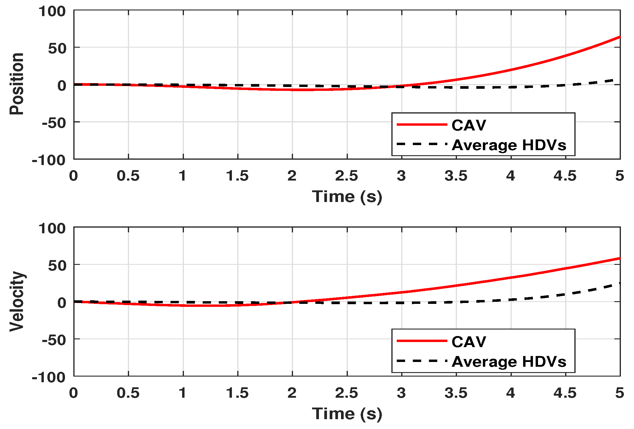
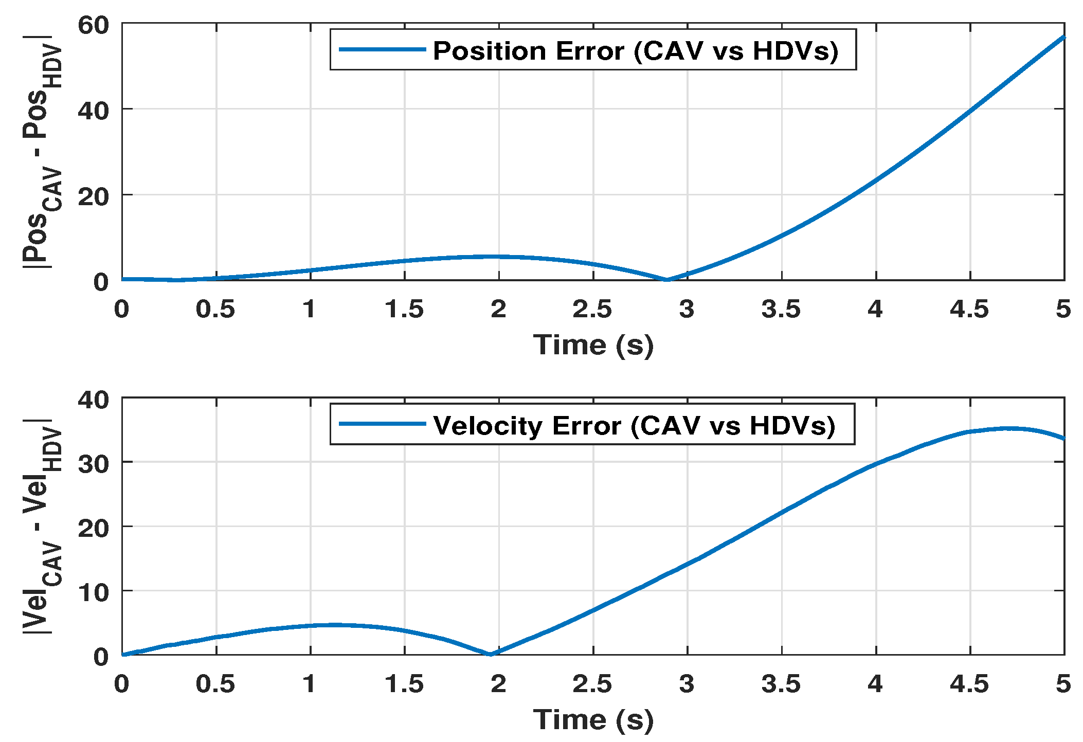
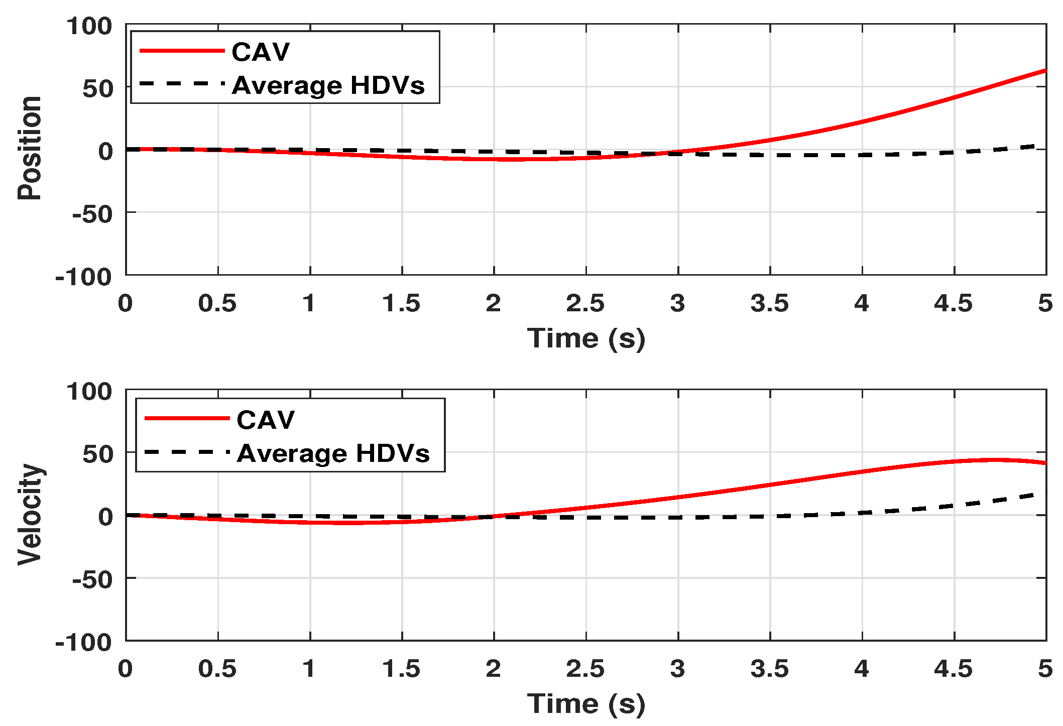
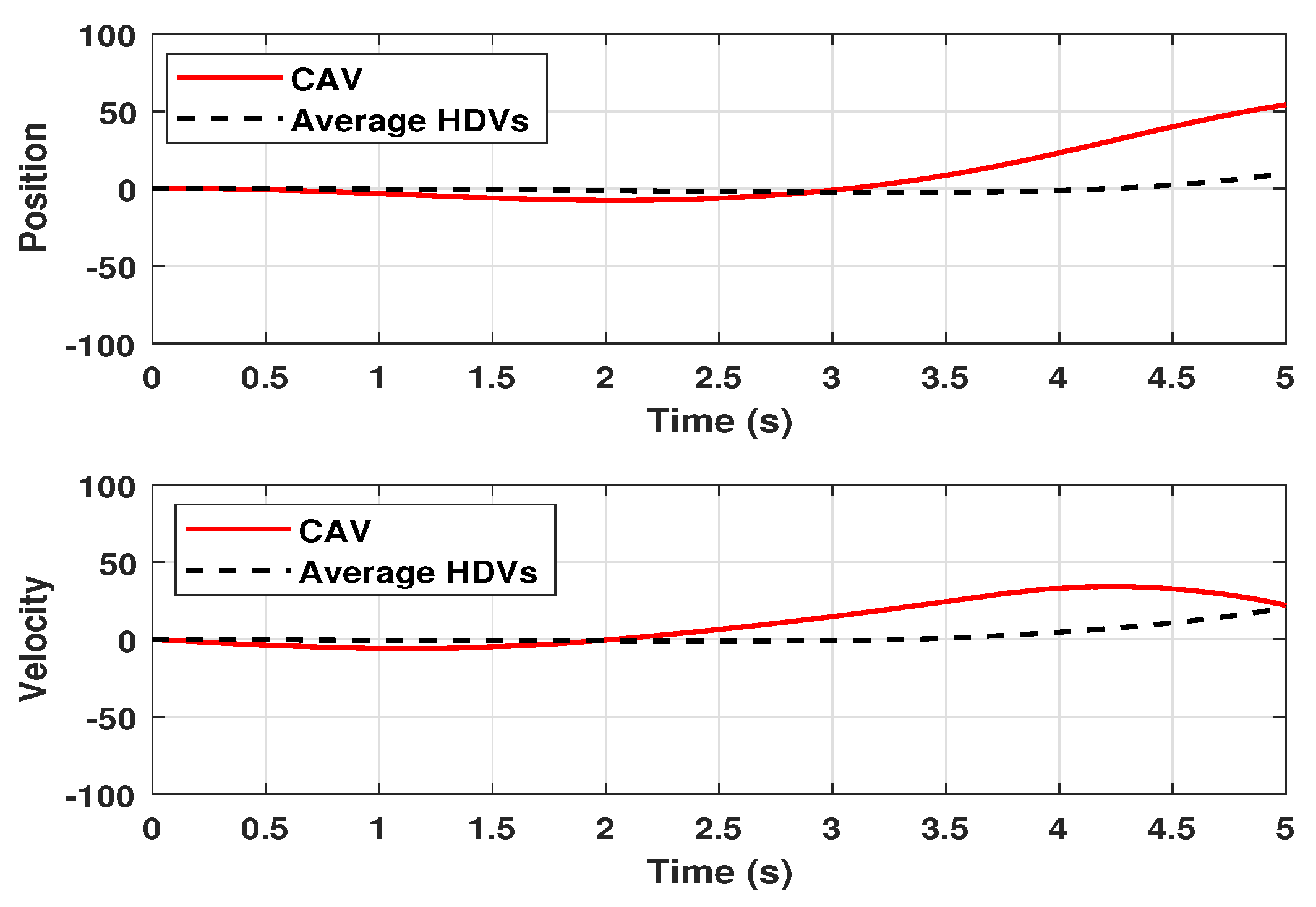
Making use of the influence of control gains, the vehicle position, velocity, and control responses of the system (25) are examined while operating under the randomized initial conditions that are illustrated in Figure 1. It is not difficult to see that the behavior of the vehicle’s position and velocity in relation to the controller of the system, which is affected by the performance of L 2 L , is in agreement with the parameter values that have been specified above. In addition, the control response curves as well as the trajectories of the average velocity and position of the CAV and HDV response curves are displayed in Figure 1 and Figure 2, respectively, which provide an indication of the performance of the proposed controller. Figure 3 depicts the position error and velocity error of the curves showing the difference between the CAV and HDVs. It has come to our attention that the outcomes of the numerical simulation provide improved stability with respect to the various speeds that are needed.
H execution: ψ 1 = I , ψ 2 = 0 , ψ 3 = γ 2 I , ψ 4 = 0 , and ς ^ = 0 ; it is simple to estimate the LMIs in Theorem 2, and the following gains are
K 1 = 1.4258 2.9052 0.7054 0.2451 0.5462 , K 2 = 0.2851 5.0215 7.4012 2.4857 0.7854 .
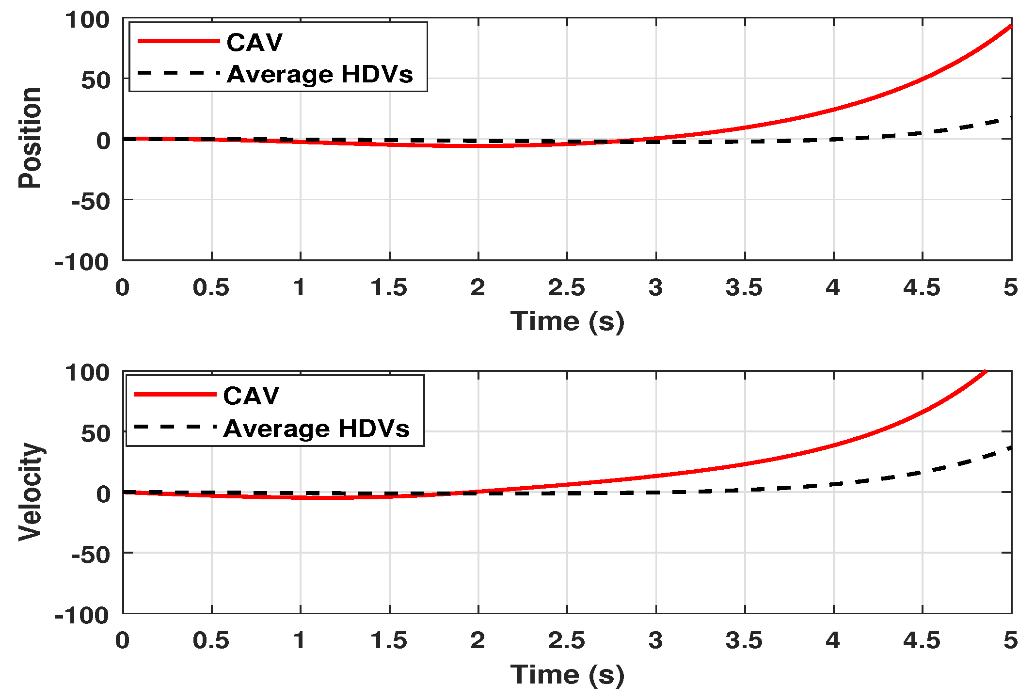
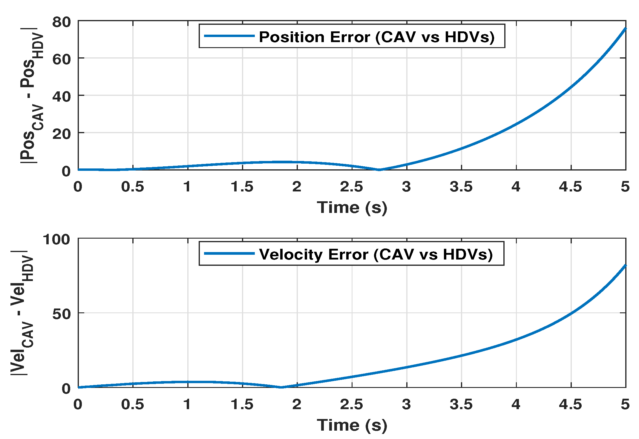
Simultaneously, the results of the numerical simulation are drawn in Figure 4 and Figure 5. These figures evaluate the following history of the vehicle position and velocity curves in relation to the gain matrices that were obtained using the input controller. Figure 6 depicts the error response curves of both the velocity and position with which the CAV and HDVs interact with one another. Because of this, the system that is being evaluated functions in an outstanding manner.
Passivity performance: ψ 1 = 0 , ψ 2 = I , ψ 3 = γ I , ψ 4 = 0 , and ς ^ = 0 are the values that are used. The focus of the coordinated system study is now shifting to the performance of the passivity. To determine whether Theorem 2 is feasible, we produce the subsequent gain by utilizing the MATLAB LMI tools within the program.
K 1 = 2.8701 0.5254 1.2274 0.3354 0.9842 , K 2 = 2.6541 5.9665 7.8770 2.5887 1.5744 .
Figure 7, Figure 8 and Figure 9 highlight the results of the numerical simulation of passivity performance. Figure 7 depicts the response curves of the vehicle position and velocity that were produced as a result of random initial conditions. The performance of the system is illustrated in Figure 7, which shows the control input performance curves. The validity of the average velocity and position and the error responses of the position and velocity of both the CAV and HDVs are represented in Figure 8 and Figure 9. The performance of the passivity analysis for the suggested model (25) is demonstrated in a clear and concise manner by this.
( Q , S , R ) -dissipativity: ψ 1 = 0.5 I , ψ 2 = I , ψ 3 = I β I , ψ 4 = 0 , and ς ^ = 0 . Similar to the previous performance, the gain matrices that are obtained by solving the inequalities of Theorem 2 and applying the parameters mentioned above are as follows:
K 1 = 4.0440 1.2440 0.6854 1.1325 0.0045 , K 2 = 3.7711 2.5584 5.4545 1.1223 0.7456 ,
and the dissipative performance vlaue of β = 0.4520 .
Meanwhile, the curves that correspond to the numerical simulation are shown in Figure 10, Figure 11 and Figure 12. Under the randomized initial condition, the appropriate vehicle position, vehicle velocity, and control input are depicted in Figure 10, together with the influence of u ( t ) . Additionally, the curve responses of the average velocity and position of the CAV and HDVs, as well as the velocity and spacing profile errors for all vehicles over time, have been displayed in Figure 11 and Figure 12, respectively. When looking at the behavior of the numerical simulation, it is discovered that the system under consideration is stable by means of the control rule that was created, even when the speeds of the vehicles are supposed to be different. As a consequence, the findings indicate that the feedback controller that was constructed is appropriate for the purpose of stabilizing the system (25). As a consequence of this, the dissipativity performance demand of ( Q , S , R ) is satisfied.
Remark 4. 
The proposed MTS significance of the extended dissipativity indices are as follows:
  • H ensures robustness against external disturbances (e.g., sudden braking or road slope), preventing amplification across the vehicle platoon.
  • L 2 L limits peak spacing or velocity deviations in response to energy-bounded driver inputs, thereby enhancing safety.
  • Passivity guarantees energy-dissipative behavior, which helps avoid oscillations and improves stability in the presence of time delay and switching dynamics.
  • ( Q , S , R ) -dissipativity provides a flexible framework to model and balance safety, comfort, and efficiency in mixed traffic environments.
These interpretations help connect the theoretical analysis to real-world applications in traffic control systems involving both HDVs and CAV.

5. Conclusions

Based on the extended dissipative theory, the issue of stability and stabilization for a delayed MTS with time-varying delay and coupling MSDC is studied. By using the standard LKFs, several sufficient conditions, and the integral inequalities, the extended dissipativity and quadratic stability can be achieved in the form of LMIs that are established in such a way that the stability of the MTS is ensured and the desired performances, such as H , L 2 L , passivity, and ( Q , S , R ) -dissipativity, are met. Then, on this basis, the coupling MSDC gains have been obtained through solving LMIs with the MATLAB toolbox. Finally, a simulation example has been employed to confirm the precision and quality of the proposed controller architecture, emphasizing its potential for resilient and efficient traffic management of the proposed MTS. Future research may expand the coupling MSDC approach to platoons of numerous CAVs to investigate cooperative control solutions in more complicated traffic circumstances. Furthermore, integrating more realistic time delay models, such as time-varying or stochastic delays, might improve the flexibility and applicability of the control method in dynamic settings.

Author Contributions

Conceptualization, P.H.; Methodology, W.S.; Software, V.R.; Validation, P.H.; Formal analysis, P.P.; Writing—original draft, W.S.; Writing—review & editing, V.R.; Supervision, V.R. and P.P. All authors have read and agreed to the published version of the manuscript.

Funding

This research received no external funding.

Data Availability Statement

No new data were created or analyzed in this study. Data sharing is not applicable to this article.

Conflicts of Interest

The authors declare no conflicts of interest.

Abbreviations

NotationRepresentation
A T / A 1 Matrix A transposition/inverse
Sym { X } X + X T
R Set of all real numbers
R 2 n 1 2 n 1 -dimensional Euclidean space
S > 0 Matrix S is symmetric and positive-definite
c o l { · } A column vector
d i a g { } A block-diagonal matrix
I n n × n identity matrix
Symmetric terms in a matrix
· Euclidean vector norm
0 n × ( s 1 ) n Zero matrix of size n × ( s 1 ) n
L 2 [ 0 , ) Space of square-integrable vector functions on [ 0 , )
P r { · } Probability
max { · } and min { · } Maximum and minimum value
sup { · } Supremum (least upper bound)

References

  1. Wang, S.T.; Zhu, W.X.; Ma, X.L. Mixed traffic system with multiple vehicle types and autonomous vehicle platoon: Modeling, stability analysis and control strategy. Phys. A Stat. Mech. Its Appl. 2023, 632, 129293. [Google Scholar] [CrossRef]
  2. Jin, S.; Sun, D.H.; Zhao, M.; Li, Y.; Chen, J. Modeling and stability analysis of mixed traffic with conventional and connected automated vehicles from cyber physical perspective. Phys. A Stat. Mech. Its Appl. 2020, 551, 124217. [Google Scholar] [CrossRef]
  3. Qin, Y.; Luo, Q.; Wang, H. Stability analysis and connected vehicles management for mixed traffic flow with platoons of connected automated vehicles. Transp. Res. Part C Emerg. Technol. 2023, 157, 104370. [Google Scholar] [CrossRef]
  4. Abou Harfouch, Y.; Yuan, S.; Baldi, S. An adaptive switched control approach to heterogeneous platooning with intervehicle communication losses. IEEE Trans. Control Netw. Syst. 2017, 5, 1434–1444. [Google Scholar] [CrossRef]
  5. Hao, W.; Rong, D.; Zhang, Z.; Byon, Y.J.; Lv, N.; Chen, Y. Stability analysis and speed-coordinated control of mixed traffic flow in expressway merging area. J. Transp. Eng. Part A Syst. 2022, 148, 04022098. [Google Scholar] [CrossRef]
  6. Milanés, V.; Shladover, S.E.; Spring, J.; Nowakowski, C.; Kawazoe, H.; Nakamura, M. Cooperative adaptive cruise control in real traffic situations. IEEE Trans. Intell. Transp. Syst. 2013, 15, 296–305. [Google Scholar] [CrossRef]
  7. Chang, X.; Li, H.; Rong, J.; Zhao, X.; Li, A.R. Analysis on traffic stability and capacity for mixed traffic flow with platoons of intelligent connected vehicles. Phys. A Stat. Mech. Its Appl. 2020, 557, 124829. [Google Scholar] [CrossRef]
  8. Yao, Z.; Hu, R.; Jiang, Y.; Xu, T. Stability and safety evaluation of mixed traffic flow with connected automated vehicles on expressways. J. Saf. Res. 2020, 75, 262–274. [Google Scholar] [CrossRef]
  9. Zheng, F.; Liu, C.; Liu, X.; Jabari, S.E.; Lu, L. Analyzing the impact of automated vehicles on uncertainty and stability of the mixed traffic flow. Transp. Res. Part C Emerg. Technol. 2020, 112, 203–219. [Google Scholar] [CrossRef]
  10. Zhang, Y.; Gao, K.; Zhang, Y.; Su, R. Traffic light scheduling for pedestrian-vehicle mixed-flow networks. IEEE Trans. Intell. Transp. Syst. 2018, 20, 1468–1483. [Google Scholar] [CrossRef]
  11. Zhang, Y.; Su, R. An optimization model and traffic light control scheme for heterogeneous traffic systems. Transp. Res. Part C Emerg. Technol. 2021, 124, 102911. [Google Scholar] [CrossRef]
  12. Zhang, B.; Zheng, W.X.; Xu, S. Filtering of Markovian jump delay systems based on a new performance index. IEEE Trans. Circuits Syst. I Regul. Pap. 2013, 60, 1250–1263. [Google Scholar] [CrossRef]
  13. Li, M.; Zhao, J.; Xia, J.; Zhuang, G.; Zhang, W. Extended dissipative analysis and synthesis for network control systems with an event-triggered scheme. Neurocomputing 2018, 312, 34–40. [Google Scholar] [CrossRef]
  14. Cai, X.; Wang, J.; Zhong, S.; Shi, K.; Tang, Y. Fuzzy quantized sampled-data control for extended dissipative analysis of T–S fuzzy system and its application to WPGSs. J. Frankl. Inst. 2021, 358, 1350–1375. [Google Scholar] [CrossRef]
  15. Cai, X.; Shi, K.; Sun, Y.; Cao, J.; Wen, S.; Qiao, C.; Tian, Z. Stability analysis of networked control systems under DoS attacks and security controller design with mini-batch machine learning supervision. IEEE Trans. Inf. Forensics Secur. 2023, 19, 3857–3865. [Google Scholar] [CrossRef]
  16. Cai, X.; Shi, K.; Sun, Y.; Cao, J.; Wen, S.; Tian, Z. Intelligent event-triggered control supervised by mini-batch machine learning and data compression mechanism for T-S fuzzy NCSs under DoS attacks. IEEE Trans. Fuzzy Syst. 2023, 32, 804–815. [Google Scholar] [CrossRef]
  17. Wu, Z.; Peng, H.; Li, F.; Huang, T.; Yang, C.; Gui, W. Extended dissipative analysis and taxiing control of fuzzy model based aircraft-on-ground systems via sliding mode approach. J. Frankl. Inst. 2022, 359, 4623–4641. [Google Scholar] [CrossRef]
  18. Gao, H.; Xia, J.; Zhuang, G.; Wang, Z.; Sun, Q. Nonfragile finite-time extended dissipative control for a class of uncertain switched neutral systems. Complexity 2017, 2017, 6581308. [Google Scholar] [CrossRef]
  19. Vadivel, R.; Njitacke, Z.T.; Shanmugam, L.; Gunasekaran, N. Dynamical analysis and reachable set estimation of TS fuzzy system with permanent magnet synchronous motor. Commun. Nonlinear Sci. Numer. Simul. 2023, 125, 107407. [Google Scholar] [CrossRef]
  20. Vadivel, R.; Wu, Y.; Chaisena, K.; Gunasekaran, N. New results on T–S fuzzy sampled-data stabilization for switched chaotic systems with its applications. Chaos Solitons Fractals 2022, 164, 112741. [Google Scholar] [CrossRef]
  21. Han, S.; Zhong, Q.; Cui, L.; Shi, K.; Cai, X.; Kwon, O.M. Extended dissipativity analysis for TS fuzzy systems based on reliable memory control and aperiodic sampled-data method. J. Frankl. Inst. 2022, 359, 2156–2175. [Google Scholar] [CrossRef]
  22. Liu, Y.; Park, J.H.; Guo, B.Z.; Shu, Y. Further results on stabilization of chaotic systems based on fuzzy memory sampled-data control. IEEE Trans. Fuzzy Syst. 2017, 26, 1040–1045. [Google Scholar] [CrossRef]
  23. Ge, C.; Shi, Y.; Park, J.H.; Hua, C. Robust H stabilization for T-S fuzzy systems with time-varying delays and memory sampled-data control. Appl. Math. Comput. 2019, 346, 500–512. [Google Scholar]
  24. Liu, Y.; Guo, B.Z.; Park, J.H.; Lee, S.M. Nonfragile exponential synchronization of delayed complex dynamical networks with memory sampled-data control. IEEE Trans. Neural Netw. Learn. Syst. 2016, 29, 118–128. [Google Scholar] [CrossRef]
  25. Ge, C.; Park, J.H.; Hua, C.; Guan, X. Nonfragile consensus of multiagent systems based on memory sampled-data control. IEEE Trans. Syst. Man Cybern. Syst. 2018, 51, 391–399. [Google Scholar] [CrossRef]
  26. Ge, C.; Park, J.H.; Hua, C.; Guan, X. Dissipativity analysis for T–S fuzzy system under memory sampled-data control. IEEE Trans. Cybern. 2019, 51, 961–969. [Google Scholar] [CrossRef]
  27. Cheng, J.; Zhang, D.; Qi, W.; Cao, J.; Shi, K. Finite-time stabilization of T–S fuzzy semi-Markov switching systems: A coupling memory sampled-data control approach. J. Frankl. Inst. 2020, 357, 11265–11280. [Google Scholar] [CrossRef]
  28. Wei, H.; Li, R.; Chen, C.; Tu, Z. Extended dissipative analysis for memristive neural networks with two additive time-varying delay components. Neurocomputing 2016, 216, 429–438. [Google Scholar] [CrossRef]
  29. Park, P.; Ko, J.W.; Jeong, C. Reciprocally convex approach to stability of systems with time-varying delays. Automatica 2011, 47, 235–238. [Google Scholar] [CrossRef]
  30. Mousavi, S.S.; Bahrami, S.; Kouvelas, A. Synthesis of output-feedback controllers for mixed traffic systems in presence of disturbances and uncertainties. IEEE Trans. Intell. Transp. Syst. 2022, 24, 6450–6462. [Google Scholar] [CrossRef]
  31. Wang, J.; Zheng, Y.; Xu, Q.; Wang, J.; Li, K. Controllability analysis and optimal control of mixed traffic flow with human-driven and autonomous vehicles. IEEE Trans. Intell. Transp. Syst. 2020, 22, 7445–7459. [Google Scholar] [CrossRef]
  32. Sugiyama, Y.; Fukui, M.; Kikuchi, M.; Hasebe, K.; Nakayama, A.; Nishinari, K.; Tadaki, S.i.; Yukawa, S. Traffic jams without bottlenecks—Experimental evidence for the physical mechanism of the formation of a jam. New J. Phys. 2008, 10, 033001. [Google Scholar] [CrossRef]
Figure 1. The trajectories of the vehicle position, vehicle velocity, and control input responses for L 2 L in Example 1.
Mathematics 13 02449 g001
Figure 2. The trajectories of the average velocity and position of the CAV and HDVs for L 2 L in Example 1.
Mathematics 13 02449 g002
Figure 3. Position error and velocity error (CAV vs. HDVs) for L 2 L in Example 1.
Mathematics 13 02449 g003
Figure 4. The vehicle position, vehicle velocity, and control input responses for H performance in Example 1.
Mathematics 13 02449 g004
Figure 5. The average velocity and position of the CAV and HDVs response curves for H performance in Example 1.
Mathematics 13 02449 g005
Figure 6. Position error and velocity error (CAV vs. HDVs) for H performance in Example 1.
Mathematics 13 02449 g006
Figure 7. The trajectories of the vehicle position, vehicle velocity, and control input for passivity performance in Example 1.
Mathematics 13 02449 g007
Figure 8. The trajectories of the average velocity and position of the CAV and HDVs for the passivity case in Example 1.
Mathematics 13 02449 g008
Figure 9. Position error and velocity error (CAV vs. HDVs) for passivity performance in Example 1.
Mathematics 13 02449 g009
Figure 10. The trajectories of the vehicle position, vehicle velocity, and control input for ( Q , S , R ) -dissipativity performance in Example 1.
Mathematics 13 02449 g010
Figure 11. The trajectories of the average velocity and position of the CAV and HDVs for ( Q , S , R ) -dissipativity performance in Example 1.
Mathematics 13 02449 g011
Figure 12. Position error and velocity error (CAV vs. HDVs) for ( Q , S , R ) -dissipativity in Example 1.
Mathematics 13 02449 g012
Table 3. Parameters values for system (25).
v * 15 m/s
α 0.5 α 0.7
θ 0.8 θ 1
S g o 30 S g o 40
S s t 3 S s t 7
v m a x 30
Table 4. Matrices for each performance in the extended dissipative case.
Analysis ψ 1 ψ 2 ψ 3 ψ 4
H case I 0 γ 2 I 0
L 2 L case00 γ 2 I I
Passivity case0I γ I 0
( Q , S , R ) -dissipativity case 0.5 I I I β I 0
Disclaimer/Publisher’s Note: The statements, opinions and data contained in all publications are solely those of the individual author(s) and contributor(s) and not of MDPI and/or the editor(s). MDPI and/or the editor(s) disclaim responsibility for any injury to people or property resulting from any ideas, methods, instructions or products referred to in the content.