Article

Capturing Discontinuities with Precision: A Numerical Exploration of 3D Telegraph Interface Models via Multi-Resolution Technique

by
Khawaja Shams Ul Haq
1,
Muhammad Asif
1,*,
Muhammad Faheem
2 and
Ioan-Lucian Popa
3,4,*
1
Department of Mathematics, University of Peshawar, Peshawar 25120, Pakistan
2
Higher Education Department, Govt. Degree College Badaber, Peshawar 25000, Pakistan
3
Department of Computing, Mathematics and Electronics, “1 Decembrie 1918” University of Alba Iulia, 510009 Alba Iulia, Romania
4
Faculty of Mathematics and Computer Science, Transilvania University of Brasov, Iuliu Maniu Street 50, 500091 Brasov, Romania
*
Authors to whom correspondence should be addressed.
Mathematics 2025, 13(15), 2391; https://doi.org/10.3390/math13152391
Submission received: 30 June 2025 / Revised: 18 July 2025 / Accepted: 21 July 2025 / Published: 25 July 2025

Abstract

This study presents a hyperbolic three-dimensional telegraph interface model with regular interfaces, numerically solved using a hybrid scheme that integrates Haar wavelets and the finite difference method. Spatial derivatives are approximated via a truncated Haar wavelet series, while temporal derivatives are discretized using the finite difference method. For linear problems, the resulting algebraic system is solved using Gauss elimination; for nonlinear problems, Newton’s quasi-linearization technique is applied. The method’s accuracy and stability are evaluated through key performance metrics, including the maximum absolute error, root mean square error, and the computational convergence rate R c ( M ) , across various collocation point configurations. The numerical results confirm the proposed method’s efficiency, robustness, and capability to resolve sharp gradients and discontinuities with high precision.

1. Introduction

Hyperbolic partial differential equations (PDEs) are commonly used to model wave propagation and dynamic systems. Their significance lies in modeling various physical phenomena. These equations play a fundamental role in understanding vibrations in structures such as buildings, beams, and machinery, as well as in atomic physics [1]. Among them, the hyperbolic telegraph equation (TE), first introduced by Heaviside in 1880, stands out due to its wide range of applications. It is particularly essential for analyzing electrical signal transmission in cables, dispersive wave propagation, the motion of viscous Maxwell fluids in parallel layers, arterial blood flow, and the random movement of insects along hedgerows [2,3]. Moreover, this equation serves as a crucial tool in studying signal propagation in transmission lines and wave phenomena. Additionally, it describes various processes in chemical, biological, and physical systems, highlighting the interplay between convection and diffusion, as well as diffusion and reaction dynamics [4,5].
Various numerical approaches have been introduced for solving 3D TEs. Urena et al. used the generalized finite difference method for the numerical solution of 3D TEs [6]. Hashmi et al. applied the compact finite difference approach for the numerical approximation of the nonlinear hyperbolic equation [7,8,9]. Xie et al. employed a fourth-order compact finite difference method combined with an alternating direction implicit (ADI) approach to address telegraph equations [10]. In a related development, Karaa and Samir proposed a higher-order ADI technique that guarantees unconditional stability for solving linear hyperbolic problems [11]. Furthermore, Mohanty, R. K. adopted an operator splitting framework to design an unconditionally stable numerical scheme for linear hyperbolic equations in three spatial dimensions with variable coefficients [12]. In addition, Deng and collaborators introduced a fourth-order compact ADI formulation for handling linear hyperbolic equations involving three spatial variables [13,14].
Many physical problems involve domains divided into multiple subregions, each characterized by distinct mathematical or physical properties. Such interfaces commonly arise in the analysis of flow behavior in composite materials or fluids. Examples include wave propagation across different media and heat transfer in rods composed of heterogeneous materials, which correspond to hyperbolic and parabolic interface problems, respectively. These interface-related challenges are significant in various scientific disciplines, including biological sciences, fluid mechanics, electromagnetic wave transmission, materials engineering, and fracture mechanics [15]. In one-dimensional settings, an interface represents a shared boundary between two intervals whereas in higher-dimensional spaces it serves as the dividing surface between different regions [16]. These regions are linked through specific jump conditions. The mathematical modeling of such interfaces involves ordinary or partial differential equations, particularly when the parameters exhibit discontinuities. Interface problems within mathematical frameworks depict scenarios where either identical or distinct materials interact across a shared boundary. A typical example is the interface between water and ice, representing a phase transition within the same material, while the boundary between water and oil illustrates an interface between two different substances [17,18].
The study of numerical methods for both regular and irregular geometries has been widely explored in the literature. Various approaches based on the finite difference method (FDM) have been proposed, including the immersed finite element technique [19], the ghost fluid approach [20], the immersed interface strategy [21], and the boundary treatment method [15]. Aziz et al. utilized Haar wavelets (HW) and radial basis functions (RBFs) to solve elliptic equations with interfaces [22], while Haider et al. extended this approach to parabolic equations [23]. Matthew applied the finite element method (FEM) to address hyperbolic equations involving interfaces [24]. Asif et al. proposed a numerical technique leveraging HWs for interface models [25], which Faisal later adapted for hyperbolic double-interface problems [26]. Kelin et al. employed the MIB Galerkin method for solving elliptic equations with interfaces [17], whereas Chen and Zou applied FEM to both elliptic and parabolic interface models [27]. Faheem et al. utilized HWCM for hyperbolic double interface problems [28]. Masood et al. developed a local RBF technique for the Stokes equation with interfaces [29], while local meshless methods were implemented for elliptic interface problems [30]. Haider et al. combined Haar wavelet and meshfree techniques to numerically solve 3D elliptic interface equations [31]. Asif et al. initially applied HWCM to the 1D telegraph interface model and also applied for the numerical solution of the 3D telegraph equation and 3D elliptic PDEs [2,26,32,33,34]. While considerable attention has been given to the study of 1D and 2D hyperbolic telegraph interface problems, 3D cases have rarely been explored using multi resolution techniques. This study aims to fill this gap by investigating 3D hyperbolic telegraph interface problems using the Haar wavelet method.
Wavelet analysis has garnered considerable attention in the realm of numerical approximations, finding applications in a wide range of fields. Various wavelets have been developed to improve estimation tasks, leveraging their efficient and effective algorithms [35]. It has been demonstrated that these wavelets work well for interpolating, solving integral equations, and handling ordinary and partial differential equations (ODEs and PDEs) [34,36,37]. In particular, HWs are remarkable for their ease of use and adaptability. Numerous fields, including data mining, pattern recognition, the theory of quantum fields, biological signal processing, denoising of images, sound compression, depict digitization, and quantum computing, have all benefited from their effective use. Haar wavelets are composed of constant box functions and have a straightforward representation with three values (−1.0, 1.0, and 0.0). Despite their benefits, the vanishing derivatives of Haar wavelets make them difficult to apply directly to PDEs. In order to overcome this, a popular method is to use Haar wavelets to estimate the highest-order derivatives, Afterward, integration is used to obtain estimated expressions for the unknown function and its lower-order derivatives. Although the literature on HWs is somewhat limited, it includes important references [2,38,39,40,41,42,43,44,45].
The HWCM is advantageous due to its simplicity and computational efficiency, leveraging the piecewise constant nature of HWs for fast and straightforward implementation. It offers adaptive resolution, allowing detailed local refinement where needed, and handles boundary conditions with ease. The method’s sparse representation reduces memory and computational costs, while its versatility extends to various differential equations in fields like physics and engineering. Good convergence properties and straightforward error estimation enhance its reliability. Additionally, it can be hybridized with other numerical methods, providing a robust and efficient solution approach for complex problems.
We provide a numerical approach to the third-order hyperbolic telegraph issue via an interface in this study. By utilizing HWCM and FDM. For the time derivatives ϑ t t and ϑ t , this method uses the second central difference and backward difference approaches, respectively. For the spatial derivatives, it uses HWCM.
The following sections make up the remainder of the manuscript: In Section 2, the governing equations are provided. Section 3 provide introductions to the HWCM and how they were modified for the situation being studied. In Section 4, implicit approaches for approximating time derivatives are provided. The suggested method’s formulation is provided in Section 5. Section 6 discusses HWCM convergence and stability analysis. The performance of the suggested approach is examined using a variety of benchmark problems in Section 7. Lastly, Section 8 presents the study’s conclusions.

2. Governing Equations

In the current work, the three-dimensional telegraph interface model of the form is
ϑ t t ( X , t ) + α ϑ t ( X , t ) + β ϑ ( X , t ) = ( k ( X , t ) ϑ ( X , t ) ) + ( k ( X , t ) ϑ ( X , t ) ) + ( k ( X , t ) ϑ ( X , t ) ) + f ( X , t ) , X Ω , t t 0 .
and the nonlinear in the form [33] is
ϑ t t ( X , t ) + α ϑ t ( X , t ) + β ϑ ( X , t ) = ( k ( X , t ) ϑ ( X , t ) ) + ( k ( X , t ) ϑ ( X , t ) ) + ( k ( X , t ) ϑ ( X , t ) ) + φ ( X , t ) + f ( X , t ) , X Ω , t t 0 .
Even though the functions ϑ ( X , t ) , f ( X , t ) , and k ( X , t ) may exhibit finite discontinuities at the interface Γ , they are assumed to be smooth within each subdomain of Ω . In this study, we choose a polynomial-type nonlinear term given by φ ( X , t ) = 2 ϑ 2 ( X , t ) . To maintain generality, and X = ( , , ) In this analysis, the interface line segment is assumed to be oriented parallel to the ⋎-axis, specifically in a three-dimensional scenario. As a result, the interface can be mathematically described as
Γ = { σ } × [ 1 , 1 ] × [ 1 , 1 ] .
This interface effectively divides the overall domain, denoted by
Ω = [ 1 , 1 ] × [ 1 , 1 ] × [ 1 , 1 ] ,
into two distinct and non-overlapping subdomains:
Ω 1 = [ 1 , σ ] × [ 1 , 1 ] × [ 1 , 1 ] ,
which represents the region to the left of the interface, and
Ω 2 = [ σ , 1 ] × [ 1 , 1 ] × [ 1 , 1 ] ,
which represents the region to the right of the interface see Figure 1.
For problems involving a single interface, the functional forms referenced in Equations (1) and (2) are specified as follows. These equations are designed to capture the behavior of the system on either side of the interface, with each subdomain potentially having different properties or behaviors. The precise forms of these equations depend on the specific nature of the problem being modeled, whether it involves linear or nonlinear dynamics, and how the interface affects the interaction between the two subdomains. The functional representations are central to characterizing the system’s behavior, particularly in ensuring that both continuity and boundary conditions at the interface are appropriately enforced:
( k ( X , t ) , ϑ ( X , t ) , f ( X , t ) ) = ( k 1 ( X , t ) , ϑ 1 ( X , t ) , f 1 ( X , t ) ) , X Ω 1 , ( k 2 ( X , t ) , ϑ 2 ( X , t ) , f 2 ( X , t ) ) , X Ω 2 .
The initial conditions for the system are defined as follows:
ϑ ( X , 0 ) = ϑ 1 ( X , 0 ) = ϑ 10 ( X ) , ϑ 2 ( X , 0 ) = ϑ 20 ( X ) .
The Dirichlet boundary conditions are prescribed by
ϑ 1 ( X , t ) = g 1 ( X , t ) , X Ω 1 Γ , ϑ 2 ( X , t ) = g 2 ( X , t ) , X Ω 2 Γ .
Here, Ω 1 and Ω 2 denote the boundaries of the subdomains Ω 1 and Ω 2 , respectively. For a domain with a single interface Γ = σ , the interface conditions are specified as follows:
ϑ 1 ( X , t ) ϑ 2 ( X , t ) = w 1 ( X , t ) , X Γ , k 1 ( X , t ) ϑ 1 ( X , t ) k 2 ( X , t ) ϑ 2 ( X , t ) = w 2 ( X , t ) , X Γ .
Within each subdomain of Ω , the functions ϑ ( X , t ) , f ( X , t ) , and k ( X , t ) are assumed to be sufficiently smooth, although they may exhibit finite, discontinuous jumps across the interface Γ . w 1 and w 2 in Equation (6). These parameters act as weighting factors introduced to distinguish the diffusion coefficients across the interface: w 1 corresponds to subdomain Ω 1 with diffusion coefficient k 1 , while w 2 relates to Ω 2 with coefficient k 2 . They are incorporated to smoothly handle discontinuities across the interface and support the Haar wavelet-based collocation process. The analytical formulation also incorporates two distinct matrix operations: the Kronecker tensor product and the Hadamard (element-wise) product.

2.1. Kronecker Tensor Product

Assume we have p × q matrix P and r × s matrix Q . Denoted by P Q , the Kronecker tensor multiplication of P and Q is a matrix of size p r × q s and has the following definition:
P Q = p 11 Q p 12 Q p 1 n Q p 21 Q p 22 Q p 2 n Q p m 1 Q p m 2 Q p m n Q .
Note: In MATLAB R2016b (Version 9.1) the built-in function kron() is used for the Kronecker tensor product.

2.2. Hadamard Product

If C and D are two vectors of the same dimension, their Hadamard product is denoted by C D and can be written as follows in a matrix:
C D = c 1 d 1 c 2 d 2 c n d n ,
where C = [ c 1 , c 2 , . . . , c n ] T and D = [ d 1 , d 2 , . . . , d n ] T .

3. Haar Wavelet Collocation Method

The HWCM is a popular and powerful numerical technique used to solve PDEs efficiently. This method is based on the Haar function, which is a simple piecewise constant function defined over a specific interval, typically denoted as [ a , b ] . The Haar function takes on constant values over different subintervals, making it ideal for approximating solutions to PDEs by dividing the domain into smaller segments. By using these constant basis functions, the HWCM transforms the original PDE problem into a system of algebraic equations that can be solved numerically. Due to its simplicity and efficiency, the HWCM is particularly useful for problems that require a fast and reliable solution while maintaining reasonable accuracy.
j ( ) = 1 if Λ 1 < Λ 2 , 1 if Λ 2 < Λ 3 , 0 otherwise ,
the parameter i represents the wavelet resolution level, while its maximum allowable value is denoted by J. The collocation points (CPs) utilized in the HWCM are defined as follows: Λ 1 = ( b a ) l m + a , Λ 2 = ( b a ) l + 0.5 m + a , and Λ 3 = ( b a ) l + 1 m + a , where j = m + l + 1 , m = 2 i , and l = 0 , 1 , 2 , , m 1 . The variable i denotes the refinement level of the wavelet resolution.
j = ( b a ) j 0.5 2 L + a , j = 1 , 2 , , 2 L ,
where L = 2 J . After the ⊺ times integration of Haar function the following functions are obtained:
, j ( ) = 0 if < Λ 1 1 ! Λ 1 if Λ 1 < Λ 2 , 1 ! Λ 1 2 Λ 2 if Λ 2 < Λ 3 , 1 ! Λ 1 2 Λ 2 + Λ 3 if > Λ 3 , = 1 , 2 ,
The Nth-order Haar matrix is given in the following form:
N = 1 ( 1 ) 2 ( 1 ) N ( 1 ) 1 ( 2 ) 2 ( 2 ) N ( 2 ) 1 ( N ) 2 ( N ) N ( N )
In a similar way, the first- and second-order integration matrices are defined as follows:
1 , N = 1 , 1 ( 1 ) 1 , 2 ( 1 ) 1 , N ( 1 ) 1 , 1 ( 2 ) 1 , 2 ( 2 ) 1 , N ( 2 ) 1 , 1 ( N ) 1 , 2 ( N ) 1 , N ( N )
and
2 , N = 2 , 1 ( 1 ) 2 , 2 ( 1 ) 2 , N ( 1 ) 2 , 1 ( 2 ) 2 , 2 ( 2 ) 2 , N ( 2 ) 2 , 1 ( N ) 2 , 2 ( N ) 2 , N ( N ) .
Furthermore, the details and execution of the method can be seen in [34,46,47,48,49].

4. Temporal Approximations

Regarding the temporal derivatives utilized in Equations (1) and (2), we consider the following two different approximations. The second-order central difference formula provided by yields an approximate value for the ϑ t t , which represents the time derivative.
ϑ t t ϑ i n + 1 2 ϑ i n + ϑ i n 1 ( Δ t ) 2 ,
where ϑ t t = ϑ t t ( , , , t ) , ϑ i n = ϑ ( , , , t ) current time level, ϑ i n + 1 = ϑ ( , , , t + Δ t ) next time level, and ϑ i n 1 = ϑ ( , , , t Δ t ) initial time level. Here, Δ t = T f N . The first-order time derivative can be estimated using the backward difference approximation, which is expressed as follows:
ϑ t ϑ i n ϑ i n 1 Δ t ,
where ϑ t = ϑ t , ϑ i n = ϑ ( , , , t ) , and ϑ i n 1 = ϑ ( , , , t Δ t ) . Here, Δ t is the time step size. The first-order backward difference is unconditionally stable and efficient in 3D problems. As a result, Equation (1) can be represented in the following implicit way:
( ϑ n + 1 2 ϑ n + ϑ n 1 ) ( Δ t ) 2 + α ( ϑ n ϑ n 1 ) Δ t + β ϑ n + 1 = k 2 ϑ n + 1 2 + ϑ n + 1 2 + ϑ n + 1 2 + f n + 1 .
By similar way substituting these approximations into the relevant equations, we obtain the above form. To get ϑ 1 n from the backward difference in the following form,
ϑ 1 n = ϑ 1 n t Δ t + ϑ 1 n 1
in this context, Equation (15) accounts for the remaining terms in the equation, where the function at the current time level is being approximated. This backward difference scheme, being implicit in nature, is employed to ensure numerical stability when solving time-dependent differential equations.

5. Formulation of the Numerical Method

The notions and implementation technique of the HWCM for conventional boundary-value problems are well-documented in previous studies [50]. In this work, we build upon these established methods by extending the framework to hyperbolic telegraph interface boundary-value problems (BVPs). In the first subinterval [ 1 , σ ] , the ⋏-axis subdivision points are the following form:
i = 1 + ( σ + 1 ) i 0.5 2 M , i = 1 , 2 , , 2 M ,
however, in the second interval [ σ , 1 ] , we assumed
i = σ + ( 1 σ ) i 0.5 2 M , i = 2 M + 1 , 2 M + 2 , , 4 M .
Using a similar approach, ⋎-axis and ⋌-axis in the interval [ 1 , 1 ] are as follows:
i = 1 + 2 ( i 0.5 ) 4 M , i = 1 , 2 , , 4 M .
and
i = 1 + 2 ( i 0.5 ) 4 M , i = 1 , 2 , , 4 M .
Let 1 = [ 1 , 2 , , 2 M ] T , 2 = [ 2 M + 1 , 2 M + 2 , , 4 M ] T , = [ 1 , 2 , , 4 M ] T and = [ 1 , 2 , , 4 M ] T
^ 1 = 1 1 4 M , ^ 2 = 2 1 4 M , ^ = 1 2 M , ^ = 1 2 M .
A column vector of size N × 1 consisting entirely of ones is denoted by 1 N . Suppose ϑ ( , , ) is a generic function of two variables. Let a ˘ = [ a 1 , a 2 , , a n ] T and b ˘ = [ b 1 , b 2 , , b n ] T be two column vectors of identical length. The following notations are introduced:
( a ˘ , b ˘ ) = [ ( a 1 , b 1 ) , ( a 2 , b 2 ) , , ( a n , b n ) ] T ,
and
ϑ ( a ˘ , b ˘ ) = [ ϑ ( a 1 , b 1 ) , ϑ ( a 2 , b 2 ) , , ϑ ( a n , b n ) ] T .
The ( ^ 1 , ^ , ^ ) vector containing all the CPs in the subdomain Ω 1 and ( ^ 2 , ^ , ^ ) containing full CPs in the subdomain Ω 2 may be obtained using these notations. The hyperbolic telegraph interface model highest-order derivatives are approximated using HWs in the HWCM. We make the following approximations for the first subdomain:
( Ω 1 = [ 1 , σ ] × [ 1 , 1 ] × [ 1 , 1 ] × [ 1 , 1 ] ) .
2 ϑ 2 = i = 1 2 M j = 1 4 M k = 1 4 M a i , j , k ( t ) i ( ) j ( ) k ( ) , ( , , ) Ω 1 ,
and
2 ϑ 2 = i = 1 2 M j = 1 4 M k = 1 4 M b i , j , k ( t ) i ( ) j ( ) k ( ) , ( , , ) Ω 2 .
Utilizing the boundary conditions, integrate the aforementioned equations to obtain the equations. Regarding ϑ , the unknown function, and the first derivative, discrete expressions apply to all of these: applying CPs. We define these in vector forms using the following notations:
ϑ 1 = 2 ϑ 1 2 ( ^ 1 , ^ , ^ , t ) , ϑ 2 = 2 ϑ 2 2 ( ^ 2 , ^ , ^ , t ) , ϑ 1 = 2 ϑ 1 2 ( ^ 1 , ^ , ^ , t ) ,
ϑ 2 = 2 ϑ 2 2 ( ^ 2 , ^ , ^ , t ) , ϑ 1 = 2 ϑ 1 2 ( ^ 1 , ^ , ^ , t ) , ϑ 2 = 2 ϑ 2 2 ( ^ 2 , ^ , ^ , t ) ,
ϑ 1 = ϑ 1 ( ^ 1 , ^ , ^ , t ) , ϑ 2 = ϑ 2 ( ^ 2 , ^ , ^ , t ) , ϑ 1 = ϑ 1 ( ^ 1 , ^ , ^ , t ) ,
ϑ 2 = ϑ 2 ( ^ 2 , ^ , ^ , t ) , ϑ 1 = ϑ 1 ( ^ 1 , ^ , ^ , t ) , ϑ 2 = ϑ 2 ( ^ 2 , ^ , ^ , t ) ,
and
ϑ 1 = ϑ 1 ( ^ 1 , ^ , ^ , t ) , ϑ 2 = ϑ 2 ( ^ 2 , ^ , ^ , t ) .
Integrating Equation (23), we obtain the following matrix form:
ϑ 1 = M 1 a ,
ϑ 1 = u 1 c + M 2 a ,
ϑ 1 = u 2 + u 3 c + M 3 a .
where
M 1 = 2 M 4 M 4 M , M 2 = ( 1 , 2 M 1 2 M S 1 ) 4 M 4 M , M 3 = ( 2 , 2 M ( 1 2 M + 1 ) S 1 ) 4 M 4 M ,
u 1 = 1 2 M I 4 M , u 2 = g 1 ( 1 8 M 2 , , t ^ ) , u 3 = ( 1 2 M + 1 ) I 4 M ,
c = ϑ 1 ( σ , 1 , 1 , t ) ϑ 1 ( σ , 2 , 2 , t ) ϑ 1 ( σ , 4 M , 4 M , t ) , a = [ a 1 , a 2 , , a 8 M 2 ] T ,
A column vector of size 2 M × 1 with the following entries is as follows: S 1 = [ 1 , 1 ( σ ) , 2 , 1 ( σ ) , , 2 M , 1 ( σ ) ] T , and I 4 M represents the identity matrix of order 4 M × 4 M .
In similar way, we integrate Equation (24) to obtain the following expressions in matrix form:
ϑ 1 = N 1 b ,
ϑ 1 = u ^ 1 + N 2 b ,
ϑ 1 = u ^ 2 + N 3 b .
where
N 1 = 2 M 4 M 4 M , N 2 = 2 M 1 , 4 M 1 2 1 4 M S 2 T , N 3 = 2 M 2 , 4 M 1 2 ( 1 4 M + ) S 2 T ,
u ^ 1 = 1 2 g 1 ( ^ 1 , 1 8 M 2 , t ) g 1 ( ^ 1 , 1 8 M 2 , t ) ,
u ^ 2 = g 1 ( ^ 1 , 1 8 M 2 , t ) + 1 2 1 8 M 2 + ^ g 1 ( ^ 1 , 1 8 M 2 , t ) g 1 ( ^ 1 , 1 8 M 2 , t ) ,
b = [ b 1 , b 2 , , b 8 M 2 ] T .
The notation S 2 with the following elements is a column vector of size 4 M × 1 :
S 2 = 1 , 2 ( 1 ) 2 , 2 ( 1 ) 4 M , 2 ( 1 ) .
Similarly, we obtain the following for the second subdomain Ω 2 = [ σ , 1 ] × [ 1 , 1 ] :
ϑ 2 = M 4 a ^ ,
ϑ 2 = u 1 c ^ + M 5 a ^ ,
ϑ 2 = u 4 u 5 c ^ + M 6 a ^ .
where
M 4 = 2 M 4 M 4 M , M 5 = 1 , 2 M 4 M 4 M , M 6 = 2 , 2 M 1 2 M S 3 4 M 4 M ,
u 4 = g 2 ( 1 8 M 2 , ^ , t ) , u 5 = ( 1 2 M 2 ) I 4 M ,
c ^ = ϑ 2 ( δ , 1 , 1 , t ) ϑ 2 ( δ , 2 , 2 , t ) ϑ 2 ( δ , 4 M , 4 M , t ) , a ^ = [ a ^ 1 , a ^ 2 , , a ^ 8 M 2 ] T .
The following items comprise the column vector of size 2 M × 1 indicated by the notation S 3 :
S 3 = 1 , 2 ( 1 ) 2 , 2 ( 1 ) 2 M , 2 ( 1 ) .
and
ϑ 2 = N 4 b ^ ,
ϑ 2 = u ^ 3 + N 5 b ^ ,
ϑ 2 = u ^ 4 + N 6 b ^ .
where
N 4 = 2 M 4 M , B 5 = 2 M 4 M 1 , 4 M 1 2 1 4 M S 2 , N 6 = 2 M 4 M 2 , 4 M 1 2 ( 1 4 M + ^ ) S 2 ,
u ^ 3 = 1 2 g 2 ( ^ 2 , 1 8 M 2 , t ) g 2 ( ^ 2 , 1 8 M 2 , t ) ,
u ^ 4 = g 2 ( ^ 2 , 1 8 M 2 , t ) + 1 2 1 8 M 2 + ^ g 2 ( ^ 2 , 1 8 M 2 , t ) g 2 ( ^ 2 , 1 8 M 2 , t ) ,
b ^ = [ b ^ 1 , b ^ 2 , , b ^ 8 M 2 ] T .
We compare Equation (30) with Equation (44) to describe b ^ in terms of a ^ and obtain the following:
u 2 + u 3 c + M 3 a = u ^ 2 + N 3 b .
From Equation (56), we have
b = ( N 3 1 M 3 ) a + ( N 3 1 u 3 ) c + N 3 1 ( u 2 u ^ 2 ) .
We may express ϑ 1 and ϑ 1 provided in Equations (34) and (35), respectively, in terms of a as follows by using the above equation of b in terms of a:
ϑ 1 = N 1 ( N 3 1 M 3 ) a + ( N 3 1 u 3 ) c + N 3 1 ( u 2 u ^ 2 ) ,
ϑ 1 = u ^ 1 + N 2 ( N 3 1 M 3 ) a + ( N 3 1 u 3 ) c + N 3 1 ( u 2 u ^ 2 ) .
Using a similar procedure, in order to represent b ^ in terms of a ^ , we compare Equation (36) with Equation (51) and obtain
u 4 u 5 c ^ + M 6 a ^ = u ^ 4 + N 6 b ^ .
From Equation (60), we have
b ^ = ( N 6 1 M 6 ) a ^ N 6 1 u 5 ) c ^ + N 6 1 ( u 4 u ^ 4 ) .
We may express ϑ 2 and ϑ 2 , provided in Equations (49) and (50), respectively, in terms of a ^ by using the above expression of b ^ in terms of a ^ as follows:
ϑ 2 = N 4 ( N 6 1 M 6 ) a ^ ( N 6 1 u 5 ) c ^ + N 6 1 ( u 4 u ^ 4 ) ,
ϑ 2 = u ^ 3 + N 5 ( N 6 1 M 6 ) a ^ ( N 6 1 u 5 ) c ^ + N 6 1 ( u 4 u ^ 4 ) .
For the third dimension, the second-order partial derivatives with respect to ⋌ are approximated using HWs.
For the first subdomain, Ω 1 = [ 1 , σ ] × [ 1 , 1 ] × [ 1 , 1 ] :
2 ϑ 2 = i = 1 2 M j = 1 4 M k = 1 4 M d i , j , k ( t ) i ( ) j ( ) k ( ) , ( , , ) Ω 1 .
For the second subdomain, Ω 2 = [ σ , 1 ] × [ 1 , 1 ] × [ 1 , 1 ] :
2 ϑ 2 = i = 1 2 M j = 1 4 M k = 1 4 M d ^ i , j , k ( t ) i ( ) j ( ) k ( ) , ( , , ) Ω 2 .
The discrete expressions for the second and first partial derivatives with respect to ⋌, evaluated at the collocation points, are
ϑ 1 = 2 ϑ 1 2 ( ^ 1 , ^ , ^ , t ) , ϑ 2 = 2 ϑ 2 2 ( ^ 2 , ^ , ^ , t ) .
ϑ 1 = ϑ 1 ( ^ 1 , ^ , ^ , t ) , ϑ 2 = ϑ 2 ( ^ 2 , ^ , ^ , t ) .
Integrating the approximation over Ω 1 with respect to ⋌, and applying boundary conditions yields
ϑ 1 = P 1 d ,
ϑ 1 = u ˜ 1 + P 2 d ,
ϑ 1 = u ˜ 2 + P 3 d .
where
P 1 = 2 M 4 M 4 M , P 2 = 2 M 4 M 1 , 4 M 1 2 1 4 M S 4 T , P 3 = 2 M 4 M 2 , 4 M 1 2 ( 1 4 M + ) S 4 T ,
u ˜ 1 = 1 2 g 1 ( ^ 1 , ^ , 1 4 M , t ) g 1 ( ^ 1 , ^ , 1 4 M , t ) , u ˜ 2 = g 1 ( ^ 1 , ^ , 1 4 M , t ) + 1 2 ( 1 4 M + ^ ) g 1 ( ^ 1 , ^ , 1 4 M , t ) g 1 ( ^ 1 , ^ , 1 4 M , t ) , d = [ d 1 , 1 , 1 , d 1 , 1 , 2 , , d 2 M , 4 M , 4 M ] T .
The column vector S 4 R 4 M × 1 :
S 4 = 1 , 2 ( 1 ) 2 , 2 ( 1 ) 4 M , 2 ( 1 )
For Ω 2 = [ σ , 1 ] × [ 1 , 1 ] × [ 1 , 1 ] :
ϑ 2 = P 4 d ^ ,
ϑ 2 = u ˜ 3 + P 5 d ^ ,
ϑ 2 = u ˜ 4 + P 6 d ^ .
where
P 4 = 2 M 4 M 4 M , P 5 = 2 M 4 M 1 , 4 M 1 2 1 4 M S 4 T , P 6 = 2 M 4 M 2 , 4 M 1 2 ( 1 4 M + ) S 4 T ,
u ˜ 3 = 1 2 g 2 ( ^ 2 , ^ , 1 4 M , t ) g 2 ( ^ 2 , ^ , 1 4 M , t ) , u ˜ 4 = g 2 ( ^ 2 , ^ , 1 4 M , t ) + 1 2 ( 1 4 M + ^ ) g 2 ( ^ 2 , ^ , 1 4 M , t ) g 2 ( ^ 2 , ^ , 1 4 M , t ) , d ^ = [ d ^ 1 , 1 , 1 , d ^ 1 , 1 , 2 , , d ^ 2 M , 4 M , 4 M ] T .
Comparing ϑ 1 from ⋏-integration (Equation (30)) and ⋌-integration (Equation (66)),
u 2 + u 3 c + M 3 a = u ˜ 2 + P 3 d .
Solving for d ,
d = ( P 3 1 M 3 ) a + ( P 3 1 u 3 ) c + P 3 1 ( u 2 u ˜ 2 ) .
Substituting into earlier equations,
ϑ 1 = P 1 ( P 3 1 M 3 ) a + ( P 3 1 u 3 ) c + P 3 1 ( u 2 u ˜ 2 ) ,
ϑ 1 = u ˜ 1 + P 2 ( P 3 1 M 3 ) a + ( P 3 1 u 3 ) c + P 3 1 ( u 2 u ˜ 2 ) .
Similarly, comparing ϑ 2 from ⋏-integration (Equation (44)) and ⋌-integration (Equation (69)),
u 4 u 5 c ^ + M 6 a ^ = u ˜ 4 + P 6 d ^ .
Solving for d ^ ,
d ^ = ( P 6 1 M 6 ) a ^ ( P 6 1 u 5 ) c ^ + P 6 1 ( u 4 u ˜ 4 ) .
Substituting into earlier equations,
ϑ 2 = P 4 ( P 6 1 M 6 ) a ^ ( P 6 1 u 5 ) c ^ + P 6 1 ( u 4 u ˜ 4 ) ,
ϑ 2 = u ˜ 3 + P 5 ( P 6 1 M 6 ) a ^ ( P 6 1 u 5 ) c ^ + P 6 1 ( u 4 u ˜ 4 ) .
Interface Conditions:
The following results are obtained by discretizing the Haar expressions after they are substituted at = σ , which is consistent with the single-line interface condition Equation (6):
u 6 + u 7 c + M 7 a u 8 u 9 c ^ M 8 a ^ = W 1
u 10 c ^ + ( u 11 M 9 ) a u 12 c ^ ( u 13 M 10 ) a ^ = W 2
where
M 7 = S 4 T ( 1 + ) S 1 T 4 M , M 8 = S 4 T S 3 T 4 M ,
M 9 = S 1 T S 1 T 4 M , M 10 = S 1 T 4 M ,
u 6 = g 1 ( 1 4 M , , t ) , u 7 = ( σ + 1 ) I 4 M , u 8 = g 2 ( 1 4 M , , t ) , u 9 = ( 1 σ ) I 4 M ,
u 10 = k 1 ( σ 4 M , , , t ) 1 4 M T I 4 M , u 11 = k 1 ( σ 4 M , , , t ) 1 8 M 2
u 12 = k 2 ( 4 M , , , t ) · 1 4 M T I 4 M , u 13 = k 2 σ 4 M , , , t 1 8 M 2 ,
W 1 = [ w 1 ( 1 ) , w 1 ( 2 ) , , w 1 ( 4 M ) ] T , w 2 = [ W 2 ( 1 ) , w 2 ( 2 ) , , w 2 ( 4 M ) ] T .
A column vector of size 2 M × 1 with the following items makes up the notation S 4 :
S 4 = [ 1 , 2 ( ) , 2 , 2 ( ) , , 2 M , 2 ( ) ] T .

5.1. Linear Case

Keeping with the implicit methodology from Equation (1), we divide the PDE into two equations, one for each of the two subdomains. The following equations are generated by replacing ϑ and its derivatives in each subdomain, together with their Haar approximations:
( 1 + α Δ t + β Δ t 2 ) I M 3 Δ t 2 k 1 I M 1 + N 1 ( N 3 1 M 3 ) + P 1 ( P 3 1 M 3 ) a + ( 1 + α Δ t + β Δ t 2 ) I u 3 Δ t 2 k 1 N 1 I + u 3 ( N 3 1 M 3 ) Δ t 2 k 1 P 1 I + u 3 ( P 3 1 M 3 ) c = ( 2 + α Δ t ) ϑ 1 n ϑ 1 n 1 + Δ t 2 f 1 + Δ t 2 N 1 ( N 3 1 ( u 2 u ^ 2 ) ) ( 1 + α Δ t + β Δ t 2 ) u 2 Δ t 2 f 1 + Δ t 2 k 1 P 1 ( P 3 1 ( u 2 u ˜ 2 ) )
and
( 1 + α Δ t + β Δ t 2 ) I M 6 k 2 Δ t 2 I M 4 + N 4 ( N 6 1 M 6 ) + P 4 ( P 6 1 M 6 ) a ^ + ( 1 + α Δ t + β Δ t 2 ) I u 5 + k 2 Δ t 2 N 4 I + u 5 ( N 6 1 M 3 ) + k 2 Δ t 2 P 4 I + u 5 ( P 6 1 M 3 ) c ^ = ( 2 + α Δ t ) ϑ 2 n ϑ 2 n 1 + Δ t 2 f 2 + k 2 Δ t 2 N 4 ( N 6 1 ( u 4 u ^ 4 ) ) + k 2 Δ t 2 P 4 ( P 6 1 ( u 4 u ˜ 4 ) ) ( 1 + α Δ t + β Δ t 2 ) u 4
In conjunction with the interface conditions specified in Equations (74) and (75), the relations in (83) and (84) form a system comprising 16 L 2 + 8 L linear equations with an equal number of unknowns: a , a ^ , c , and c ^ . The unknown vector a is obtained by solving the linear system Xa = b , where X denotes the coefficient matrix and b represents the known right-hand side vector. The approximate solutions within each subdomain at time t are then computed using Equations (30) and (44). This iterative process is repeated N times to estimate ϑ ( , , t ) at the final time level t = T f .

5.2. Nonlinear Case

Using the quasi-linearization technique (QLT) [51], the equations for the nonlinear PDEs provided in Equation (2) are first linearized.
ϑ ϑ n + 1 = ϑ n ϑ n + 1 + ϑ n + 1 ϑ n ϑ n ϑ n ,
and then applying the HWCM, we obtain the following system of equations
Φ M 1 a , N 1 b , P 1 d , u 1 c + M 2 a r ^ 1 + N 2 b , u 2 + u 3 c + M 3 a , k 1 ( v ^ 1 , ^ ) , ϕ 1 ( v 1 , ^ ) ^ 1 , ^ = f 1 ( v ^ 1 , ^ )
Φ M 4 a ^ , N 4 b ^ , P 4 d ^ , u 1 c ^ + M 5 a ^ r ^ 3 + N 5 b ^ , u 4 u 5 c ^ + M 6 a ^ , k 2 ( v ^ 2 , ^ ) , ϕ 2 ( v ^ 2 , ^ ) v ^ 2 , ^ = f 2 ( v ^ 2 , ^ )
Combining the system of Equation (86) and (87) and then following a similar approach to that discussed in Section 5.1 for the solution of 3D hyperbolic telegraph interface problems, we can get Xa = b as well; however, here it is a nonlinear system of equations that can be handled by nonlinear solvers.

6. Convergence Criteria and Stability

The effectiveness of numerical methods relies on two key criteria: convergence and stability. In this section, we will explore each concept individually.

6.1. Convergence of HWCM

Theorem 1.
Suppose that all the partial derivatives of ϑ, namely, ϑ t , ϑ t t , ϑ t t t , ϑ , ϑ , ϑ , ϑ , ϑ , ϑ , ϑ , ϑ , ϑ , ϑ , ϑ , ϑ , and ϑ exist and remain bounded in the domain ( a , b ) 2 × [ 0 , T ] . Let M = 2 J for J = 0 , 1 , 2 , and p = 0 , 1 , , P , where P N . If ϑ M p represents the solution obtained using the Haar wavelet method and ϑ is the exact solution, then
max 0 p P ϑ ( . , t p ) ϑ M p O 1 M 2 M 2 M 2 + O ( Δ t ) , as J and Δ t 0 ,
where Δ t = max 0 p P 1 ( t p + 1 t p ) .
Proof. 
Following [52], this statement can also be proven. □

6.2. Stability of HWCM

To assess the stability of the proposed HWCM, we can refer to the key definition provided in LeVeque’s 2007 work on numerical schemes [53].
Definition 1.
Consider the system of equations Xa = b which are obtained by applying the proposed numerical approach to the interface problem. A numerical approach will be stable if the inverse of X is bounded:
X 1 l o ,
where l o is a constant.
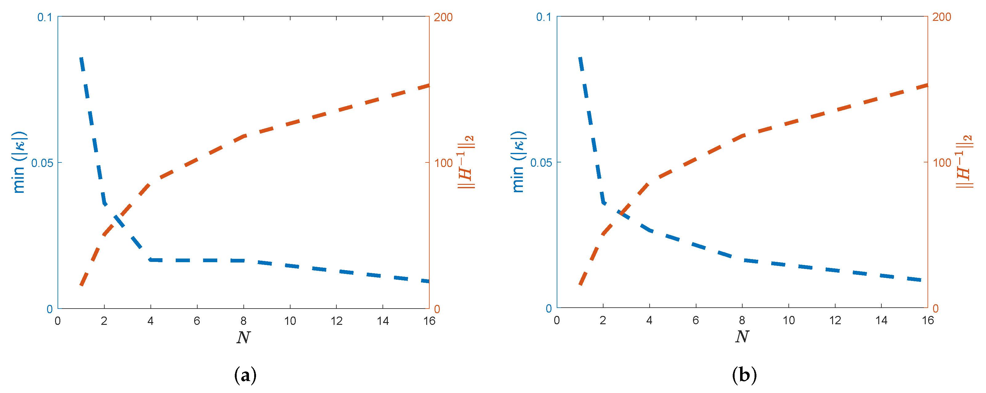
Following Definition 1, we have determined the lowest values of the eigenvalues of X , represented by κ , reflecting the spectral radius magnitudes of X 1 , as indicated in Figure 2, in order to examine the stability of the HWCM. Furthermore, when resolution M = N / 2 increases, as seen in the aforementioned figures, the 2-norm of X 1 for different circumstances does not grow quickly. As a result, HWCM is stable since the approach meets the stability requirement given in Definition 1.
We also examined the eigenvalues of X and observed that the matrix X ’s greatest eigenvalues at each time step, which represent the corresponding Haar weights. According to Figure 3, the greatest eigenvalues of matrix X continuously stay away from zero, which is a necessary requirement for the stability of the suggested method to have non-singularity about X .

7. Numerical Validation

To assess the performance of the proposed HWCM, a series of numerical experiments are carried out, as outlined in the earlier sections, on different three-dimensional hyperbolic telegraph PDEs featuring a single interface. The method’s accuracy and computational efficiency are examined by comparing the L norm errors and CPU times. Furthermore, the convergence behavior of the HWCM is analyzed by computing its numerical convergence rate using the following formula:
R ( N ) = 1 log ( 2 ) log L ( N / 2 ) L ( N ) ,
where L ( N ) represents the L error associated with N collocation points.
The numerical implementations were performed on a computer equipped with an Intel (R) Core (TM) i3-3110M processor operating at 2.40 GHz and 8 GB of RAM and running Windows 10. The CPU time for each example, measured in seconds, is provided in the corresponding tables. For computationally intensive cases involving a larger number of collocation points, MATLAB Online was utilized to access enhanced processing capabilities.
Example 1.
The initial case of the linear hyperbolic telegraph interface model is presented below, with parameters α = 1 and β = 1 .
ϑ t t ( X , t ) + α ϑ t ( X , t ) + β ϑ ( X , t ) = k 1 ( X ) ( ϑ 1 ( X , t ) + ϑ 1 ( X , t ) + ϑ 1 ( X , t ) ) + f 1 , 1 σ , k 2 ( X ) ( ϑ 2 ( X , t ) + ϑ 2 ( X , t ) + ϑ 2 ( X , t ) ) + f 2 , σ 1 .
With the following exact analytical solution:
ϑ ( X , t ) = ϑ 1 ( X , t ) = e + t sin , 1 σ , ϑ 2 ( X , t ) = e + t 2 , σ 1 ,
and
k ( X , t ) = k 1 ( X , t ) = 1 , 1 σ , k 2 ( X , t ) = 2 , σ 1 .
The problem is subject to the following boundary conditions:
ϑ 1 ( 1 , , , t ) = e + t sin ( 1 ) ,   ϑ 1 ( , 1 , , t ) = e 1 + t sin ( ) ,
ϑ 1 ( , , 1 , t ) = e 1 t sin ( ) ,   ϑ 2 ( 1 , , , t ) = e 1 + t ,
ϑ 2 ( , 1 , , t ) = e 1 + t 2 ,   ϑ 2 ( , , 1 , t ) = e 1 + t 2 ,
ϑ 1 ( , 1 , , t ) = e 1 + t sin ( ) ,   ϑ 1 ( , , 1 , t ) = e + 1 t sin ( ) .
subject to the ICs
ϑ ( , , , 0 ) = ϑ 1 ( X , 0 ) = e + sin , 1 σ , ϑ 2 ( X , 0 ) = e + 2 , σ 1 .
and interface conditions
ϑ 2 ( 0 , , , t ) ϑ 1 ( 0 , , , t ) = 0 ,
k 2 ϑ 2 ( 0 , , , t ) k 1 ϑ 1 ( 0 , , t ) = e + t
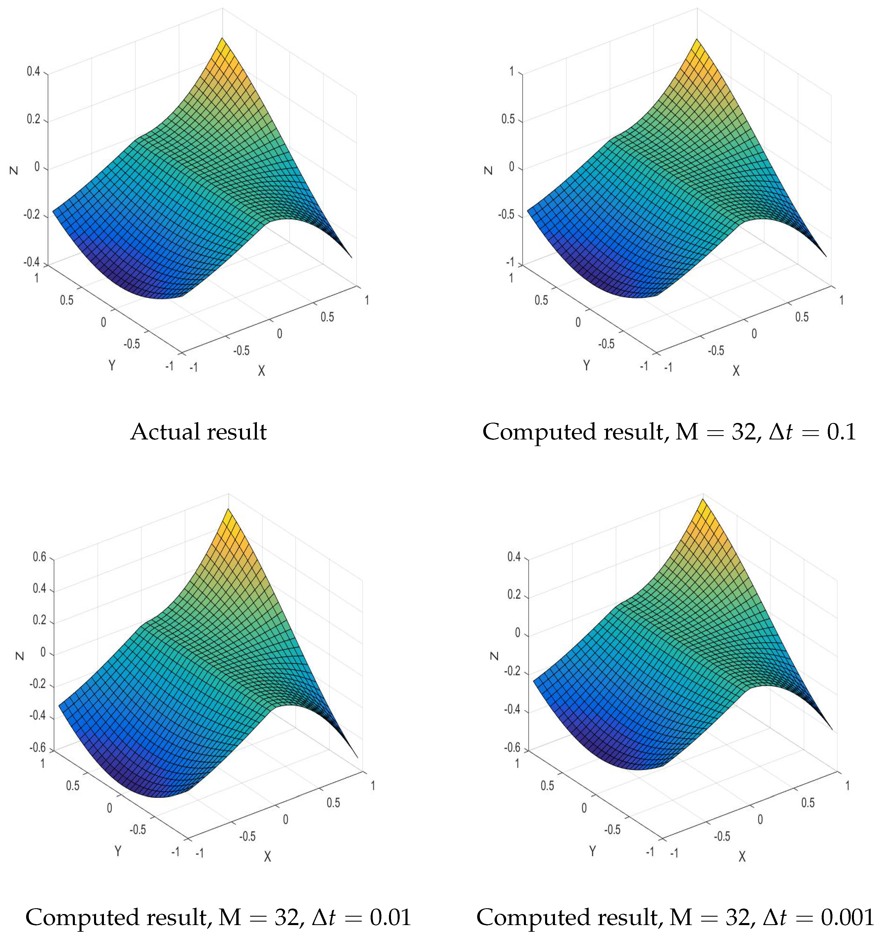
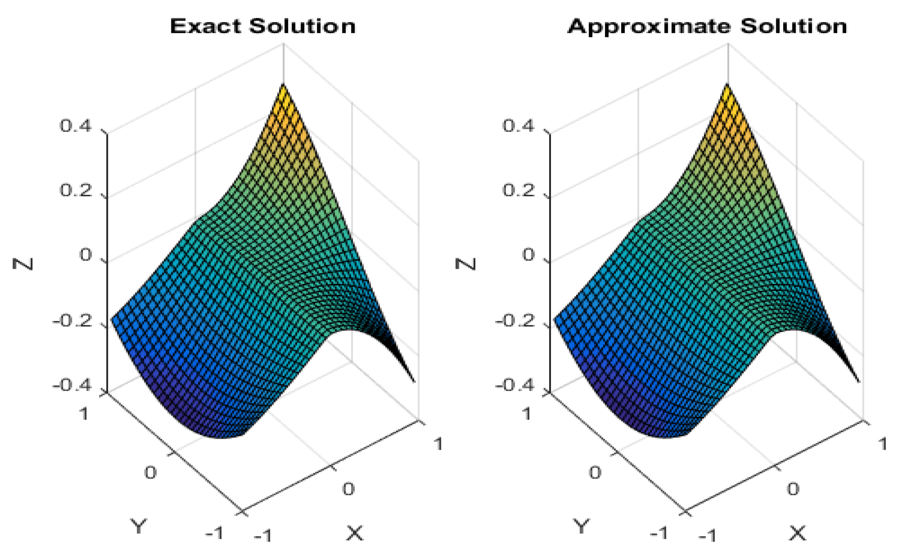
This is the first linear example involving an interface. This example is solved using the current approach; the numerical results are shown in Table 1 and Table 2. We calculate rate of convergence R c ( N ) , root mean square errors (RMSEs), and maximum absolute errors (MAEs) for a variety of time steps and CP numbers. Even with a small amount of collocation sites, the findings demonstrate that the MAE decreases to the order of 10 5 , indicating relatively excellent accuracy for practical applications. A higher number of grids can lead to greater accuracy. Furthermore, to provide a clearer image of the inaccuracies, Figure 4 shows 3D graphs of exact and approximate results for various numbers of CPs, i.e., Δ t = 0.1 , Δ t = 0.01 , Δ t = 0.001 , and M = 32 . From the graph in Figure 4, it is evident that the estimate solution closely aligns with the true solution. Additionally, Table 3 confirms the attainment of first-order convergence in time.
Example 2.
The following is a linear hyperbolic telegraph interface model with parameters α = 1 and β = 1 .
ϑ t t ( X , t ) + α ϑ t ( X , t ) + β ϑ ( X , t ) = k 1 ( X ) ( ϑ 1 ( X , t ) + ϑ 1 ( X , t ) + ϑ 1 ( X , t ) ) + f 1 , 1 σ , k 2 ( X ) ( ϑ 2 ( X , t ) + ϑ 2 ( X , t ) + ϑ 2 ( X , t ) ) + f 2 , σ 1 .
With the exact solution
ϑ ( X , t ) = ϑ 1 ( X , t ) = e t sin cos cos , 1 σ , ϑ 2 ( X , t ) = 2 ( t + 2 + 2 ) , σ 1 ,
and
k ( X , t ) = k 1 ( X , t ) = 1 , 1 σ , k 2 ( X , t ) = 10 , σ 1 .
The boundary conditions are given by
ϑ 1 ( 1 , , , t ) = e t sin ( 1 ) cos ( ) cos ( ) ,   ϑ 1 ( , 1 , , t ) = e t sin ( ) cos ( 1 ) cos ( ) ,
ϑ 1 ( , , 1 , t ) = e t sin ( ) cos ( ) cos ( 1 ) ,   ϑ 2 ( 1 , , , t ) = ( t + 2 + 2 ) ,
ϑ 2 ( , 1 , , t ) = 2 ( t + 1 + 2 ) ,   ϑ 2 ( , , 1 , t ) = 2 ( t + 2 + 1 ) ,
ϑ 1 ( , 1 , , t ) = e t sin ( ) cos ( 1 ) cos ( ) ,   ϑ 1 ( , , 1 , t ) = e t sin ( ) cos ( ) cos ( 1 ) .
subject to the ICs
ϑ ( , , , 0 ) = ϑ 1 ( X , 0 ) = sin ( ) cos ( ) cos ( ) , 1 σ , ϑ 2 ( X , 0 ) = ( ) 2 ( ( ) 2 + ( ) 2 ) , σ 1 .
and interface conditions
ϑ 2 ( 0 , , , t ) ϑ 1 ( 0 , , , t ) = 0 ,
k 2 ϑ 2 ( 0 , , , t ) k 1 ϑ 1 ( 0 , , t ) = e t cos ( ) cos ( )
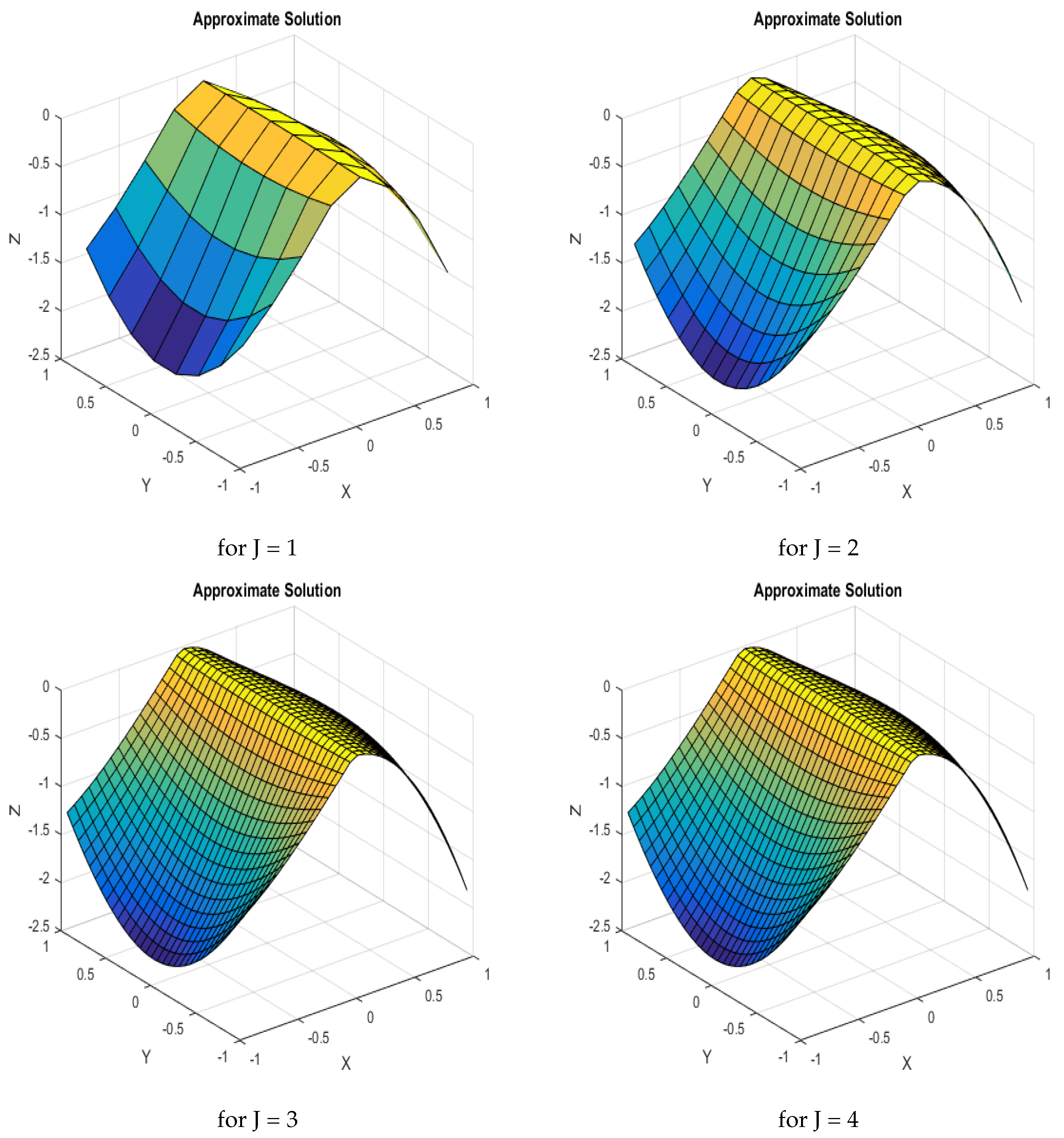
This linear test case features a single interface, to which the proposed method has been successfully applied. The corresponding numerical outcomes are summarized in Table 4 and Table 5. We have evaluated the MAEs, RMSEs, and the convergence rate R c ( M ) for different numbers of CPs across multiple time levels. The results in the tables indicate that the HWCM yields nearly identical minimal error values for a time step of 0.1 . However, improved accuracy is achieved when the time step is refined to 0.01 , demonstrating a significant enhancement in HWCM’s performance. The computed R c ( N ) values listed in Table 5 align closely with the theoretical expectations established by Majak et al. Furthermore, three-dimensional visualizations provided in Figure 5 depict the solution behavior for varying numbers of CPs.
Example 3.
We now consider the following linear hyperbolic telegraph interface model with α = 1 and β = 1 .
ϑ t t ( X , t ) + α ϑ t ( X , t ) + β ϑ ( X , t ) = k 1 ( X ) ( ϑ 1 ( X , t ) + ϑ 1 ( X , t ) + ϑ 1 ( X , t ) ) + f 1 , 1 σ , k 2 ( X ) ( ϑ 2 ( X , t ) + ϑ 2 ( X , t ) + ϑ 1 ( X , t ) ) + f 2 , σ 1 .
with the exact solution
ϑ ( X , t ) = ϑ 1 ( X , t ) = e t sin cos cos , 1 σ , ϑ 2 ( X , t ) = e t 2 sin sin , σ 1 ,
and
k ( X , t ) = k 1 ( X , t ) = 1 , 1 σ , k 2 ( X , t ) = 100 , σ 1 .
The boundary conditions are given by
ϑ 1 ( 1 , , , t ) = e t sin ( 1 ) cos ( ) cos ( ) ,   ϑ 1 ( , 1 , , t ) = e t sin ( ) cos ( 1 ) cos ( ) ,
ϑ 1 ( , , 1 , t ) = e t sin ( ) cos ( ) cos ( 1 ) ,   ϑ 2 ( 1 , , , t ) = e t sin ( ) sin ( ) ,
ϑ 2 ( , 1 , , t ) = e t 2 sin ( 1 ) sin ( ) ,   ϑ 2 ( , , 1 , t ) = e t 2 sin ( ) sin ( 1 ) ,
ϑ 1 ( , 1 , , t ) = e t sin ( ) cos ( 1 ) cos ( ) ,   ϑ 1 ( , , 1 , t ) = e t sin ( ) cos ( ) cos ( 1 ) .
subject to the ICs
ϑ ( , , , 0 ) = ϑ 1 ( X , 0 ) = e + sin , 1 σ , ϑ 2 ( X , 0 ) = e + 2 , σ 1 .
and interface conditions
ϑ 2 ( 0 , , , t ) ϑ 1 ( 0 , , , t ) = 0 ,
k 2 ϑ 2 ( 0 , , , t ) k 1 ϑ 1 ( 0 , , t ) = e + t
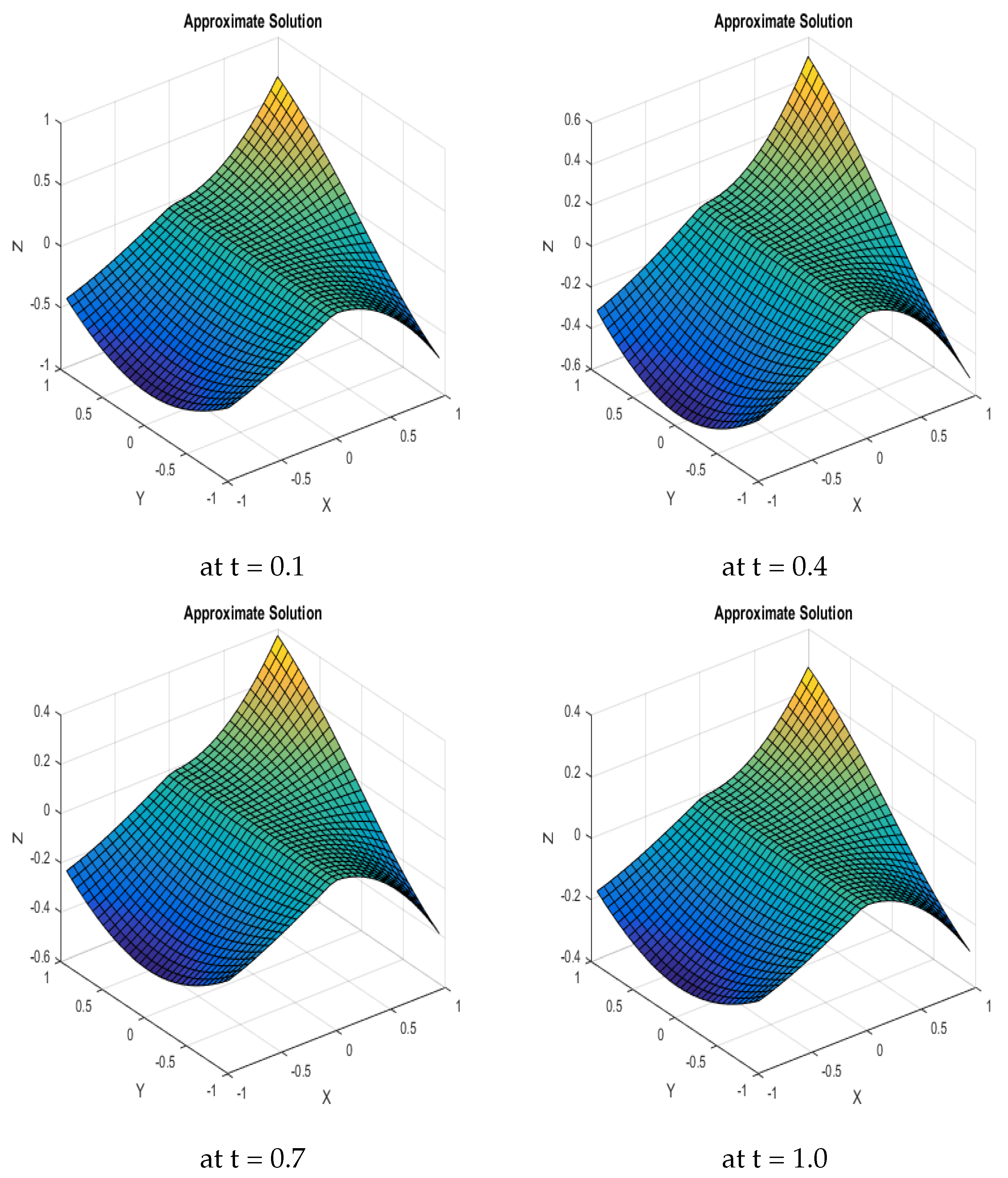
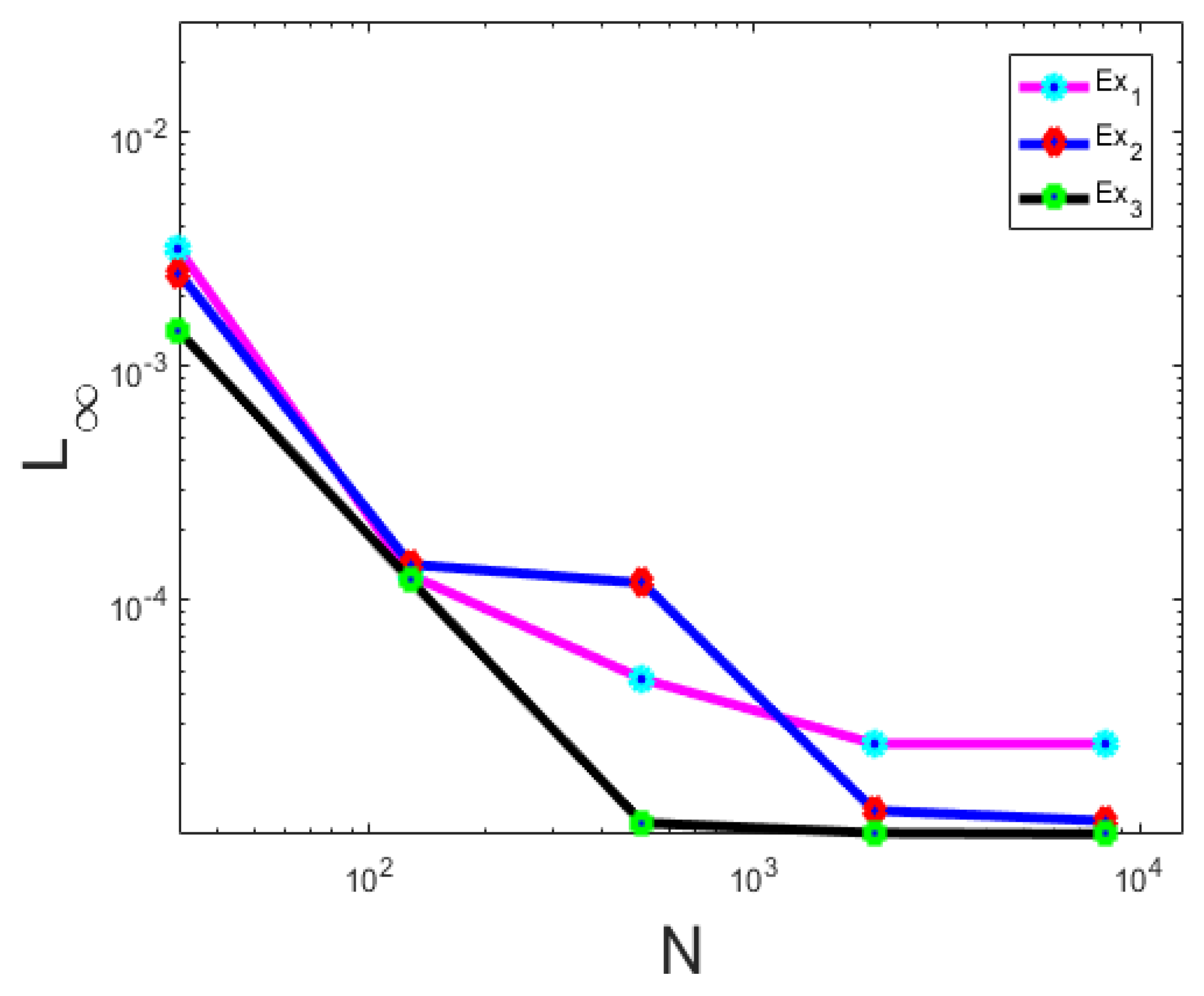
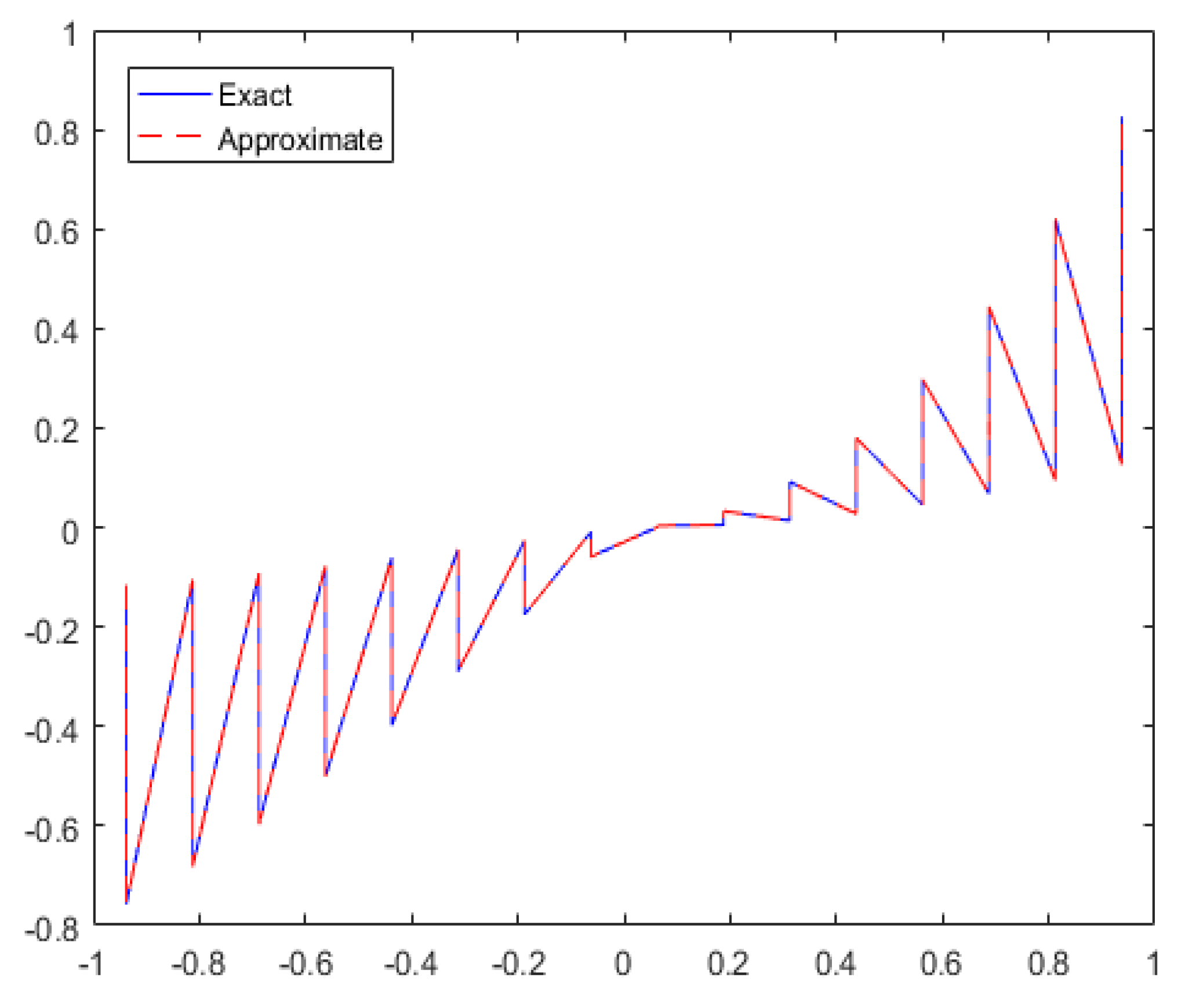
This is another linear example, and the results obtained at various points are summarized in Table 6. We computed different types of errors, which highlight the strong performance of the proposed method. While increasing the number of CPs leads to improved accuracy, it also increases the computational cost for 3D problems. This trade-off demonstrates the method’s capability for achieving good accuracy. The convergence rate, calculated from the results, approaches a value of 2 as the number of CPs increases. Figure 6 displays surface plots of the approximate solutions obtained using HWCM at different time steps: t = 0.1 , t = 0.4 , t = 0.7 , and t = 1 . These plots effectively showcase the method’s ability to capture the essential features of the complex interface problem. In Figure 7, we present an error comparison graph for Examples 1–3 with varying numbers of CPs. Additionally, Figure 8 shows a 2D error graph for Example 3, providing further insight into the accuracy of the approach.
Example 4.
The model under consideration is a nonlinear hyperbolic telegraph interface equation characterized by α = 1 and β = 1 .
ϑ t t ( X , t ) + α ϑ t ( X , t ) + β ϑ ( X , t ) = k 1 ( X ) ( ϑ 1 ( X , t ) + ϑ 1 ( X , t ) + ϑ 1 ( X , t ) ) + 2 ϑ 1 2 + f 1 , 1 σ , k 2 ( X ) ( ϑ 2 ( X , t ) + ϑ 2 ( X , t ) + ϑ 1 ( X , t ) ) + 2 ϑ 2 2 + f 2 , σ 1 ,
This has the following exact solution:
ϑ ( X , t ) = ϑ 1 ( X , t ) = e + t sin , 1 σ , ϑ 2 ( X , t ) = e + t 2 , σ 1 ,
and
k ( X , t ) = k 1 ( X , t ) = 1 , 1 σ , k 2 ( X , t ) = 2 , σ 1 .
The boundary conditions are given by
ϑ 1 ( 1 , , , t ) = e + t sin ( 1 ) ,   ϑ 1 ( , 1 , , t ) = e 1 + t sin ( ) ,
ϑ 1 ( , , 1 , t ) = e 1 t sin ( ) ,   ϑ 2 ( 1 , , , t ) = e 1 + t ,
ϑ 2 ( , 1 , , t ) = e 1 + t 2 ,   ϑ 2 ( , , 1 , t ) = e 1 + t 2 ,
ϑ 1 ( , 1 , , t ) = e 1 + t sin ( ) ,   ϑ 1 ( , , 1 , t ) = e + 1 t sin ( ) .
subject to the ICs
ϑ ( , , , 0 ) = ϑ 1 ( X , 0 ) = e + sin , 1 σ , ϑ 2 ( X , 0 ) = e + 2 , σ 1 .
and interface conditions
ϑ 2 ( 0 , , , t ) ϑ 1 ( 0 , , , t ) = 0 ,
k 2 ϑ 2 ( 0 , , , t ) k 1 ϑ 1 ( 0 , , t ) = e + t
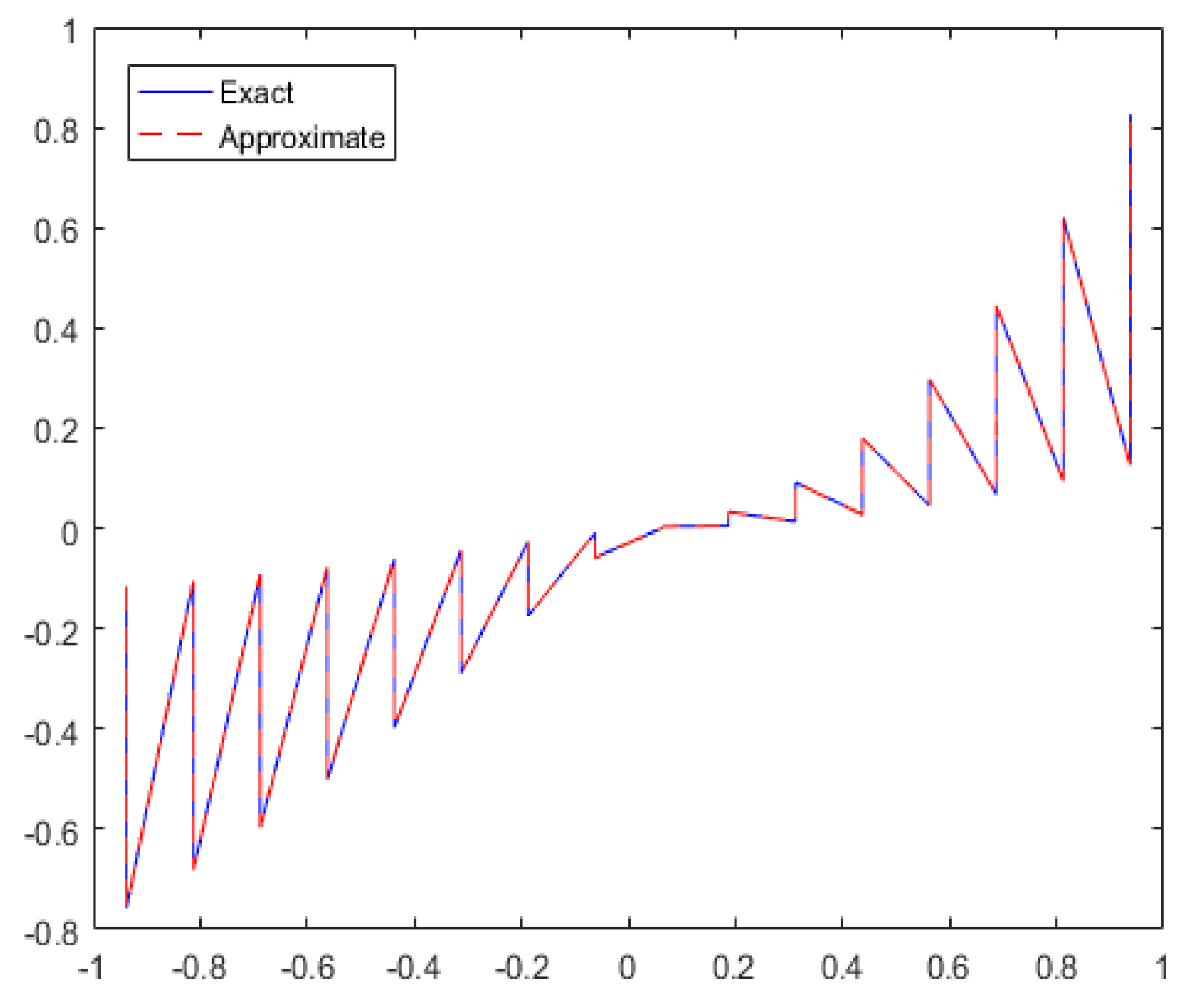
This nonlinear example has been evaluated, and the numerical results for various numbers of CPs are summarized in Table 7. This table includes key metrics such as the MAEs, RMSEs, and the R c ( M ) across various numbers of CPs. A notable aspect of the method is that increasing the number of CPs consistently reduces the error, achieving an error order of 10 5 at a relatively low computational cost. To handle the nonlinear terms, the quasi-Newton formula is employed. The results clearly show that this method is effective for addressing nonlinear problems. Figure 9 presents a comparison of estimate and true solutions, illustrating excellent agreement between them. The numerical results demonstrate both high accuracy and efficiency, with the convergence rate approaching 2, validating the effectiveness of the new approach.
Example 5.
A nonlinear hyperbolic telegraph interface model with α = 1 and β = 1 is examined below.
ϑ t t ( X , t ) + α ϑ t ( X , t ) + β ϑ ( X , t ) = k 1 ( X ) ( ϑ 1 ( X , t ) + ϑ 1 ( X , t ) + ϑ 1 ( X , t ) ) + 2 ϑ 1 2 + f 1 , 1 σ , k 2 ( X ) ( ϑ 2 ( X , t ) + ϑ 2 ( X , t ) + ϑ 1 ( X , t ) ) + 2 ϑ 2 2 + f 2 , σ 1 ,
This has the exact solution
ϑ ( X , t ) = ϑ 1 ( X , t ) = e t sin cos cos , 1 σ , ϑ 2 ( X , t ) = e t 2 sin sin , σ 1 ,
and
k ( X , t ) = k 1 ( X , t ) = 1 , 1 σ , k 2 ( X , t ) = 100 , σ 1 .
The boundary conditions are given by
ϑ 1 ( 1 , , , t ) = e t sin ( 1 ) cos ( ) cos ( ) ,   ϑ 1 ( , 1 , , t ) = e t sin ( ) cos ( 1 ) cos ( ) ,
ϑ 1 ( , , 1 , t ) = e t sin ( ) cos ( ) cos ( 1 ) ,   ϑ 2 ( 1 , , , t ) = e t · 1 2 · sin ( ) sin ( ) ,
ϑ 2 ( , 1 , , t ) = e t 2 sin ( 1 ) sin ( ) ,   ϑ 2 ( , , 1 , t ) = e t 2 sin ( ) sin ( 1 ) ,
ϑ 1 ( , 1 , , t ) = e t sin ( ) cos ( 1 ) cos ( ) ,   ϑ 1 ( , , 1 , t ) = e t sin ( ) cos ( ) cos ( 1 ) .
subject to the ICs
ϑ ( , , , 0 ) = ϑ 1 ( X , 0 ) = e + sin , 1 σ , ϑ 2 ( X , 0 ) = e + 2 , σ 1 .
and interface conditions
ϑ 2 ( 0 , , , t ) ϑ 1 ( 0 , , , t ) = 0 ,
k 2 ϑ 2 ( 0 , , , t ) k 1 ϑ 1 ( 0 , , t ) = e + t
This final nonlinear example has been examined, with the results for different numbers of CPs summarized in Table 8. Both Table 8 and Figure 10 provide a detailed view of these results. The efficiency of the approach is evaluated by measuring the error norms of the approximate solutions in comparison to the exact solutions. Additionally, the table presents the CPU time ratios and R c ( M ) for this example, showcasing the technique’s novel features. The results indicate that the proposed method significantly enhances both accuracy and efficiency. By increasing the number of CPs, the method effectively reduces errors while maintaining a manageable computational cost and demonstrating favorable convergence rates. This confirms the robustness and practical value of the technique. Overall, the results validate that the new method is well-suited for solving nonlinear examples with high precision and offers a reliable solution for addressing complex scenarios in practical applications.

8. Conclusions

In this study, we employ a simple yet effective numerical approach that combines the HWCM with the FDM to solve the 3D TE with a regular interface. This method is not only computationally efficient but also straightforward to implement on a computer. We have validated this approach on a range of 3D linear and nonlinear problems, yielding highly promising results. A significant reduction in the maximum absolute error is observed as more collocation points are employed, highlighting the effectiveness of this approach. The integration of the HWCM with the FDM leverages the strengths of both techniques. The Haar wavelet method offers excellent localization properties and is well-suited for handling problems with sharp gradients or discontinuities, while the finite difference method provides a straightforward framework for numerical approximation, making it a valuable complement to the wavelet approach. The combined method’s computational efficiency does not come at the expense of accuracy. On the contrary, our results show that even with a modest number of collocation points, the method yields solutions with a high degree of accuracy. Specifically, we obtained a MAE of the order 10 5 , a RMSE of the order 10 5 , and a convergence rate R c ( M ) 2 for j = 3 , confirming the method’s second-order accuracy in space and first-order accuracy in time and overall robustness. The method’s ability to strike a balance between accuracy and computational efficiency makes it especially appealing for real-world applications, where time and computing resources are typically limited.

Author Contributions

Conceptualization, M.A.; data curation, K.S.U.H. and M.A.; formal analysis, K.S.U.H., M.A., I.-L.P. and M.F.; funding acquisition, I.-L.P.; investigation, K.S.U.H. and I.-L.P.; methodology, M.A. and M.F.; project administration, M.A. and I.-L.P.; resources, M.A.; software, M.A. and M.F.; supervision, M.A.; validation, M.A., M.F. and K.S.U.H.; visualization, K.S.U.H. and M.F.; writing—original draft, K.S.U.H., M.A. and M.F.; writing—review and editing, I.-L.P., M.A. and M.F. All authors have read and agreed to the submitted version of the manuscript.

Funding

This study was conducted without the support of any external funding sources.

Data Availability Statement

No datasets were generated or analyzed during the course of this research; therefore, data sharing does not apply to this article.

Conflicts of Interest

The authors affirm that there are no financial or personal conflicts of interest that could have influenced the outcomes or interpretation of this research.

References

  1. Okubo, A. Application of the Telegraph Equation to Oceanic Diffusion; Chesapeake Bay Institute, The Johns Hopkins University: Baltimore, MD, USA, 1971. [Google Scholar]
  2. Asif, M.; Bilal, F.; Khan, I. Extension of Haar wavelet technique for numerical solution of three dimensional linear and nonlinear telegraph equations. Partial. Differ. Equ. Appl. Math. Model. 2023, 9, 100618. [Google Scholar] [CrossRef]
  3. Dhunde, R.R.; Waghmare, G.L. Double Laplace transform combined with iterative method for solving non-linear telegraph equation. J. Indian Math. Soc. 2016, 83, 221–230. [Google Scholar]
  4. Weston, V.H. Wave splitting of telegraph equation in R 3 and its application to inverse scattering. Inverse Probl. 1993, 9, 783–797. [Google Scholar] [CrossRef]
  5. Gao, F.; Chi, C. Unconditionally stable difference schemes for a one-space-dimensional linear hyperbolic equation. Appl. Math. Comput. 2007, 187, 1272–1276. [Google Scholar] [CrossRef]
  6. Ureña, F.; Gavete, L.; Benito, J.J.; García, A.; Vargas, A.M. Solving the telegraph equation in 2-D and 3-D using generalized finite difference method (GFDM). Eng. Anal. Bound. Elem. 2020, 112, 13–24. [Google Scholar] [CrossRef]
  7. Zhang, Y.; Wang, X. Explicit High-Order Compact Difference Method for Solving Nonlinear Hyperbolic Equations. J. Comput. Phys. 2025, 400, 105678. [Google Scholar]
  8. Singh, I.; Kumari, U. Solving 2D and 3D Telegraph Equations with Elzaki Transform and Homotopy Perturbation Method. J. Mech. Contin. Math. Sci. 2024, 18–29. [Google Scholar] [CrossRef]
  9. Abdelkawy, M.A.; Izadi, M.; Adel, W. Robust and Accurate Numerical Framework for Multi-Dimensional Fractional-Order Telegraph Equations Using Jacobi/Jacobi-Romanovski Spectral Technique. Bound. Value Probl. 2024, 2024, 131. [Google Scholar] [CrossRef]
  10. Xie, S.-S.; Yi, S.-C.; Kwon, T.I. Fourth-order compact difference and alternating direction implicit schemes for telegraph equations. Comput. Phys. Commun. 2012, 183, 552–569. [Google Scholar] [CrossRef]
  11. Karaa, S. Unconditionally stable ADI scheme of higher-order for linear hyperbolic equations. Int. J. Comput. Math. 2010, 87, 3030–3038. [Google Scholar] [CrossRef]
  12. Mohanty, R.K. An operator splitting technique for an unconditionally stable difference method for a linear three space dimensional hyperbolic equation with variable coefficients. Appl. Math. Comput. 2005, 162, 549–557. [Google Scholar] [CrossRef]
  13. Jiwari, R.; Pandit, S. A differential quadrature algorithm to solve the two dimensional linear hyperbolic telegraph equation with Dirichlet and Neumann boundary conditions. Appl. Maths. Comput. 2012, 218, 7279–7294. [Google Scholar] [CrossRef]
  14. Dehghan, M.; Salehi, R. A method based on meshless approach for the numerical solution of the two-space dimensional hyperbolic telegraph equation. Math. Methods Appl. Sci. 2012, 35, 1220–1233. [Google Scholar]
  15. Zhou, Y.C.; Zhao, S.; Feig, M.; Wei, G. High order matched interface and boundary method for elliptic equations with discontinuous coefficients and singular sources. J. Comput. Phys. 2006, 213, 1–30. [Google Scholar] [CrossRef]
  16. Zhou, Y.C.; Zhao, S. A matched interface and boundary method for solving multi-flow Navier Stokes equations with applications to geodynamics. J. Comput. Phys. 2012, 231, 223–242. [Google Scholar] [CrossRef]
  17. Xia, K.; Zhan, M.; Wei, G.W. MIB Galerkin method for elliptic interface problems. J. Comput. Appl. Math. 2014, 272, 195–220. [Google Scholar] [CrossRef] [PubMed]
  18. Lee, L.; LeVeque, R.J. An immersed interface method for incompressible Navier-Stokes equations. SIAM J. Sci. Comput. 2003, 25, 832–856. [Google Scholar] [CrossRef]
  19. Liu, W.K.; Liu, Y.; Farrell, D.; Zhang, L. Immersed finite element method and its applications to biological systems. Comput. Methods Appl. Mech. Eng. 2006, 195, 1722–1749. [Google Scholar] [CrossRef] [PubMed]
  20. Liu, X.D.; Sideris, C.T. Convergence of the ghost fluid method for elliptic equations with interfaces. Maths. Comput. 2003, 72, 1731–1746. [Google Scholar] [CrossRef]
  21. LeVeque, R.J.; Li, Z. The Immersed Interface Method for elliptic equations with discontinuous coefficients and singular sources. SIAM J. Numer. Anal. 1994, 31, 1019–1044. [Google Scholar] [CrossRef]
  22. Imran, A.; Siraj, I.; Nadeem, H. Meshless and multi-resolution collocation techniques for steady state interface models. Int. J. Comput. Methods 2018, 15, 1750073. [Google Scholar]
  23. Imran, A.; Siraj, I. Nadeem H. Meshless and multi-resolution collocation techniques for parabolic interface models. Appl. Math. Comput. 2018, 335, 313–332. [Google Scholar]
  24. Matthew, A. On finite element method for linear hyperbolic interface problems. J. Niger. Math. Soc. 2018, 37, 41–55. [Google Scholar]
  25. Rana, G.; Asif, M.; Haider, N.; Bilal, R.; Ahsan, M.; Al-Mdallal, Q.; Jarad, F. A modified algorithm based on Haar wavelets for the numerical simulation of interface models. J. Funct. Spaces 2022, 2022, 1541486. [Google Scholar] [CrossRef]
  26. Asif, M.; Farooq, M.U.; Riaz, M.B.; Bilal, F.; Haider, N. Numerical assessment of hyperbolic type double interface problems via Haar wavelets. Partial. Differ. Equ. Appl. Math. 2024, 10, 100665. [Google Scholar] [CrossRef]
  27. Chen, Z.; Zou, Z. Finite element methods and their convergence for elliptic and parabolic interface problems. Numeri. Math. 1998, 79, 175–202. [Google Scholar] [CrossRef]
  28. Faheem, M.; Asif, M.; Haider, N.; Amin, R.; Mdallal, Q.A. Hybrid Haar wavelet and meshfree methods for hyperbolic double interface problems: Numerical implementations and comparative performance Analysis. Partial. Differ. Equ. Appl. Math. 2024, 11, 100773. [Google Scholar] [CrossRef]
  29. Masood, A.; Abdul, B.; Siraj, I. Local radial basis function collocation method for stokes equations with interface conditions. Eng. Anal. Bound. Elem. 2020, 119, 246–256. [Google Scholar]
  30. Masood, A.; Elisabeth, L. Local meshless methods for second order elliptic interface problems with sharp corners. J. Comput. Phys. 2020, 416, 109599. [Google Scholar] [CrossRef]
  31. Haider, N.; Aziz, I. Numerical solution of 2D and 3D elliptic-type interface models with regular interfaces. Eng. Comput. 2019, 35, 1081–1102. [Google Scholar] [CrossRef]
  32. Asif, M.; Faisal, B.; Mehnaz, S.; Rubi, B.; Haider, N. An efficient algorithm for the numerical solution of telegraph interface model with discontinuous coefficients via Haar wavelets. Alex Eng. J. 2023, 72, 275–285. [Google Scholar] [CrossRef]
  33. Asif, M.; Bilal, F.; Haider, N.; Jarad, F. Robust numerical techniques for modeling telegraph equations in multi-scale and heterogeneous environments. J. Appl. Math. Comput. 2025. [Google Scholar] [CrossRef]
  34. Aziz, I.; Asif, M. Haar wavelet collocation method for three-dimensional elliptic partial differential equations. Comput. Math. Appl. 2017, 73, 2023–2034. [Google Scholar] [CrossRef]
  35. Maleknejad, K.; Lotfi, T.; Mahdiani, K. Numerical solution of first kind Fredholm integral equations with wavelets-Galerkin method (WGM) and wavelets precondition. Appl. Math. Comput. 2007, 186, 794–800. [Google Scholar] [CrossRef]
  36. Dahmen, W.; Kurdila, A.; Oswald, P. Multiscale Wavelet Methods for Partial Differential Equations; Elsevier: Amsterdam, The Netherlands, 1997. [Google Scholar]
  37. Wu, J. A wavelet operational method for solving fractional partial differential equations numerically. Appl. Math. Comput. 2009, 214, 31–40. [Google Scholar] [CrossRef]
  38. Imran, A.; Siraj, I.; Wajid, K. Quadrature rules for numerical integration based on Haar wavelets and hybrid functions. Comput. Math. Appl. 2011, 61, 2770–2781. [Google Scholar] [CrossRef]
  39. Asif, M.; Haider, N.; Qasem, A.; Imran, K. A Haar wavelet collocation approach for solving one and two-dimensional second-order linear and nonlinear hyperbolic telegraph equations. Numer. Methods Partial. Differ. Equ. 2020, 36, 1962–1981. [Google Scholar] [CrossRef]
  40. Siraj, I.; Aziz, I.; Fazal, H. A comparative study of numerical integration based on Haar wavelets and hybrid functions. Comput. Math. Appl. 2010, 59, 2026–2036. [Google Scholar] [CrossRef]
  41. Siraj, I.; Aziz, I.; Fayyaz, M. A new approach for numerical solution of integro-differential equations via Haar wavelets. Int. J. Comput. Math. 2013, 90, 1971–1989. [Google Scholar] [CrossRef]
  42. Jiwari, R.; Pandit, S.; Mittal, R.C. A differential quadrature algorithm for the numerical solution of the second-order one dimensional hyperbolic telegraph equation. Int. J. Nonlinear Sci. 2012, 13, 259–266. [Google Scholar]
  43. Jiwari, R.; Kumar, V.; Karan, R.; Alshomrani, A.S. Haar wavelet quasilinearization approach for MHD Falkner Skan flow over permeable wall via Lie group method. Int. J. Numer. Methods Heat Fluid Flow 2017, 27, 1332–1350. [Google Scholar] [CrossRef]
  44. Pandit, S.; Jiwari, R.; Bedi, K.; Koksal, M.E. Haar wavelets operational matrix based algorithm for computational modelling of hyperbolic type wave equations. Eng. Comput. 2017, 34, 793–814. [Google Scholar] [CrossRef]
  45. Lepik, U.; Hein, H. Haar Wavelets: With Applications; Springer: Cham, Switzerland, 2014. [Google Scholar]
  46. Priyadarshi, G.; Kumar, R. Reconstruction of the parameter in parabolic partial differential equations using Haar wavelet method. Eng. Compu. 2020, 38, 2415–2433. [Google Scholar] [CrossRef]
  47. Hazarika, B.; Methi, G.; Aggarwal, R. Application of generalized Haar wavelet technique on simultaneous delay differential equations. J. Comput. Appl. Math. 2024, 449, 115977. [Google Scholar] [CrossRef]
  48. Sinha, A.; Kumar, S. Introducing higher-order Haar wavelet method for solving three-dimensional partial differential equations. Int. J. Wavelets Multiresolution Inf. Process. 2024, 22, 2350040. [Google Scholar] [CrossRef]
  49. Lepik, U. Numerical solution of evolution equations by the Haar wavelet method. Appl. Math. Comput. 2007, 185, 695–704. [Google Scholar] [CrossRef]
  50. Chen, C. Haar wavelet method for solving lumped and distributed-parameter systems. IEE Proc.-Control Theory Appl. 1997, 144, 87–94. [Google Scholar] [CrossRef]
  51. Bellman, R.E.; Kalaba, R.E. Quasilinearization and Nonlinear Boundary-Value Problems; American Elsevier Publishing Company Inc.: New York, NY, USA, 1965. [Google Scholar]
  52. Ahsan, M.; Thanh, T.; Hussain, I. A multiresolution collocation method and its convergence for Burgers’ type equations. Math. Methods Appl. Sci. 2023, 46, 11702–11725. [Google Scholar] [CrossRef]
  53. LeVeque, R.J. Finite Difference Methods for Ordinary and Partial Differential Equations: Steady-State and Time-Dependent Problems; SIAM: Philadelphia, PA, USA, 2007. [Google Scholar]
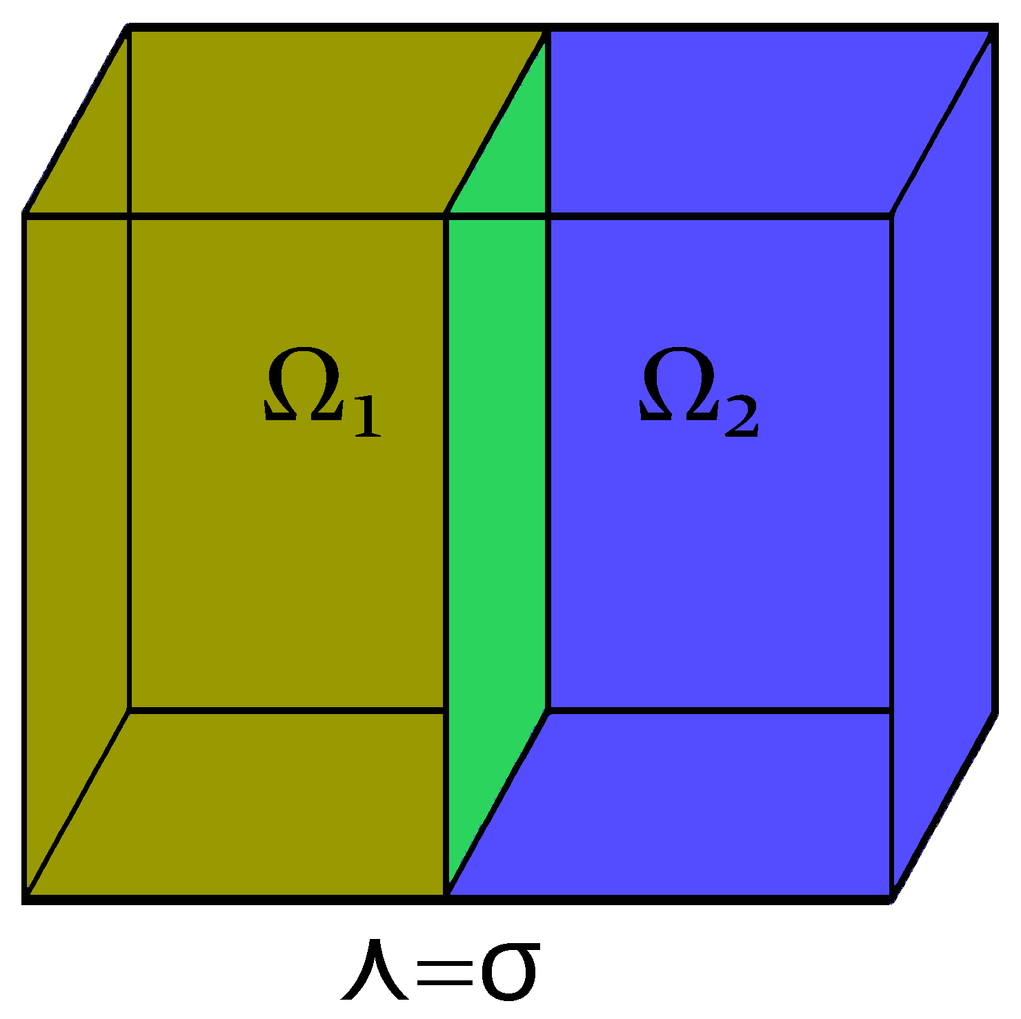
Figure 1. Three-dimensional view of the proposed problem with highlighted subdomains and interface.
Mathematics 13 02391 g001
Figure 2. For Examples 1 (a) and 4 (b), respectively, the 2-norm and spectral radius magnitudes of X 1 of the suggested technique at Δ t = 0.01 , t = 1 .
Mathematics 13 02391 g002
Figure 3. The stability analysis of the suggested approach for Examples 1 (a) and 4 (b), respectively, for J = 3 , Δ t = 0.1 16 , and 0 t 1 .
Mathematics 13 02391 g003
Figure 4. True and estimate solutions are compared for the given Example 1.
Mathematics 13 02391 g004
Figure 5. Example 2 approximate answers using HWCM for varying CP counts at t = 1.
Mathematics 13 02391 g005
Figure 6. Use HWCM at various time steps to approximate the solutions to Example 3 for J = 3 and Δ t = 0.01 / 32 .
Mathematics 13 02391 g006
Figure 7. Error comparison of Examples 1–3 for different collocation points.
Mathematics 13 02391 g007
Figure 8. True and approximate results compared for Example 3.
Mathematics 13 02391 g008
Figure 9. Comparison of exact and approximate solutions for Example 4.
Mathematics 13 02391 g009
Figure 10. For Example 5, exact and approximate solutions are examined for J = 3 and Δ t = 0.01 .
Mathematics 13 02391 g010
Table 1. The HWCM based numerical solution corresponding to Example 1 at time t = 1 is presented.
JN Δ t E c (M) RMSE CPU Time Ratio (Seconds) R c (M)
0 8 × 4 × 4 0.1 / 4 3.1000 × 10 3 9.0226 × 10 4
1 16 × 8 × 8 0.1 / 8 2.3850 × 10 3 4.0503 × 10 4 0.3472 1.7175
2 32 × 16 × 16 0.1 / 16 1.1599 × 10 3 1.8274 × 10 4 5.1913 1.7391
3 64 × 32 × 32 0.1 / 32 7.4341 × 10 4 6.4703 × 10 5 30.1343 1.5980
Table 2. HWCM-based numerical solutions for Example 2 at t = 1 .
JN Δ t E c (M) RMSE CPU Time Ratio (Seconds) R c (M)
0 8 × 4 × 4 0.01 / 4 1.1725 × 10 3 3.0975 × 10 4
1 16 × 8 × 8 0.01 / 8 5.2843 × 10 4 1.3659 × 10 4 0.4996 1.3121
2 32 × 16 × 16 0.01 / 16 2.6155 × 10 4 4.4697 × 10 5 9.4118 1.4136
3 64 × 32 × 32 0.01 / 32 3.4341 × 10 5 1.2199 × 10 5 98.6410 1.5948
Table 3. Example 1: J = 2 , and T = 1 . The theoretical order of convergence is 1 (see Theorem 1).
Δ t E Computational Order of ConvergenceCPU Time (Seconds)
1 / 10 2.3794 × 10 3 0.0115
1 / 20 1.3716 × 10 3 0.79320.1643
1 / 40 8.4382 × 10 4 0.70010.2987
1 / 80 6.0817 × 10 4 0.77110.3357
1 / 160 4.1382 × 10 4 0.85470.6822
1 / 320 2.1038 × 10 4 0.97490.8846
Table 4. HWCM-based numerical solutions for Example 2 at t = 1 .
JN Δ t E c (M) RMSE CPU Time Ratio (Seconds) R c (M)
0 8 × 4 × 4 0.1 / 4 9.0573 × 10 3 6.3841 × 10 3
1 16 × 8 × 8 0.1 / 8 2.9402 × 10 3 2.3849 × 10 3 5.8319 1.4042
2 32 × 16 × 16 0.1 / 16 8.3074 × 10 4 1.0731 × 10 3 11.9520 1.3270
3 64 × 32 × 32 0.1 / 32 2.2752 × 10 4 9.8426 × 10 4 91.9531 1.4918
Table 5. HWCM-based numerical solutions for Example 2 at t = 1 .
JN Δ t E c (M) RMSE CPU Time Ratio (Seconds) R c (M)
0 8 × 4 × 4 0.01 / 4 7.0085 × 10 4 7.7410 × 10 4
1 16 × 8 × 8 0.01 / 8 3.4834 × 10 4 2.6419 × 10 4 7.9546 1.6802
2 32 × 16 × 16 0.01 / 16 6.1627 × 10 5 8.7892 × 10 5 53.9032 1.5719
3 64 × 32 × 32 0.01 / 32 1.9314 × 10 5 1.2469 × 10 5 75.1052 1.5219
Table 6. Results of Example 3 computed with HWCM at t = 1 .
JN Δ t E c (M) RMSE CPU Time Ratio (Seconds) R c (M)
0 8 × 4 × 4 0.01 / 4 4.2184 × 10 4 5.6203 × 10 4
1 16 × 8 × 8 0.01 / 8 2.0185 × 10 4 2.9170 × 10 4 2.4105 1.7320
2 32 × 16 × 16 0.01 / 16 5.5196 × 10 5 8.4251 × 10 5 58.3195 1.6241
3 64 × 32 × 32 0.01 / 32 1.9310 × 10 5 3.1934 × 10 5 76.9304 1.6208
Table 7. Computed outcomes using HWCM for Problem 4 at t = 1 .
JN Δ t E c (M) RMSE CPU Time Ratio (Seconds) R c (M)
0 8 × 4 × 4 0.01 / 4 3.3961 × 10 4 3.7042 × 10 4
1 16 × 8 × 8 0.01 / 8 9.5417 × 10 5 1.5297 × 10 4 3.5643 1.5672
2 32 × 16 × 16 0.01 / 16 3.7159 × 10 5 7.3215 × 10 5 49.0931 1.7302
3 64 × 32 × 32 0.01 / 32 1.6923 × 10 5 2.4595 × 10 5 79.5241 1.4170
Table 8. Computational outcomes for Problem 5 at t = 1 with HWCM.
JN Δ t E c (M) RMSE CPU Time Ratio (Seconds) R c (M)
0 8 × 4 × 4 0.01 / 4 3.4631 × 10 3 4.7940 × 10 4
1 16 × 8 × 8 0.01 / 8 6.5739 × 10 4 1.6529 × 10 4 3.5710 1.3919
2 32 × 16 × 16 0.01 / 16 9.7682 × 10 5 8.0929 × 10 5 29.0913 1.4318
3 64 × 32 × 32 0.01 / 32 1.3905 × 10 5 3.7023 × 10 5 89.5621 1.2306
Disclaimer/Publisher’s Note: The statements, opinions and data contained in all publications are solely those of the individual author(s) and contributor(s) and not of MDPI and/or the editor(s). MDPI and/or the editor(s) disclaim responsibility for any injury to people or property resulting from any ideas, methods, instructions or products referred to in the content.