Article

General Approach to the Evolving Plasma Equilibria with a Resistive Wall in Tokamaks

by
Vladimir D. Pustovitov
1,2,* and
Nikolay V. Chukashev
1,3
1
National Research Centre Kurchatov Institute, 123182 Moscow, Russia
2
National Research Nuclear University Moscow Engineering Physics Institute, 115409 Moscow, Russia
3
Phystech School of Electronics, Photonics and Molecular Physics, Moscow Institute of Physics and Technology (State University), 115184 Dolgoprudny, Russia
*
Author to whom correspondence should be addressed.
Mathematics 2023, 11(8), 1885; https://doi.org/10.3390/math11081885
Submission received: 27 February 2023 / Revised: 6 April 2023 / Accepted: 15 April 2023 / Published: 16 April 2023
(This article belongs to the Special Issue Dynamics and Control Theory with Applications)

Abstract

:
The dynamic problem of plasma equilibrium in a tokamak is considered taking into account the electromagnetic reaction of the vacuum vessel resistive wall. The currents induced in the wall during transient events contribute to the external magnetic field that determines the plasma shape and position. Accordingly, the plasma geometry must evolve so that the inductive excitation of the wall current would properly compensate for the resistive losses. Simultaneous consideration of these factors presents the main difficulty of the description. It is performed in a general form using the Green’s function method that guarantees the mathematical accuracy of expressions for the magnetic fields from each source. At the same time, it is desirable to minimize the related complications, which is one of the goals here. The starting point is the standard solution of the external equilibrium problem given by integral relating the poloidal magnetic flux to the magnetic field at the plasma boundary. In the evolutionary problem, the additional equations for the plasma-wall electromagnetic coupling are transformed to an equation with a similar integral over the wall, but with either the time derivative of the poloidal magnetic flux or the wall current density in the integrand. The mentioned similarity allows to use the already developed techniques, which makes this formulation compact and convenient. It provides the basis for extension of the existing analytical theory of equilibrium to the case with non-circular plasma and wall.

1. Introduction

In tokamaks, the mass density ρ of the plasma is very low, so the inertia force in the equation of motion
ρ d v d t = p + j × B
can be neglected even when describing the integral consequences of the disruptions [1,2,3,4,5,6,7,8,9]. In such cases, in the so-called equilibrium equation
p = j × B
the plasma pressure p , the magnetic field
B = B p l + B e x t
and the current density
j = × B / μ 0
must be considered as functions of time t . Then, a solution will be time-dependent, and the transition from one equilibrium state to another will give the plasma velocity v (for example, of global horizontal and vertical motions). This velocity is a hidden parameter in (2), so formally v appears to satisfy the boundary conditions on the plasma-vacuum interface. It is affected by the currents induced in the metallic environment. They contribute to B e x t = B B p l , where B p l is the field created by the plasma currents.
The accuracy of analytical predictions based on Equation (2) is confirmed by numerical calculations of the disruption induced forces on the tokamak vacuum chamber (wall) [6,7,8,9,10,11,12,13]. This encourages further expansion of the equilibrium theory, but, with such additional elements as B / t 0 and the resistive wall, the incompleteness or inapplicability of some standard elements are revealed. For example, it was recently established [14] that the equation for the evolution of the toroidal plasma shift Δ b , obtained by Shafranov in [15] and reproduced in well-known reviews [16,17], can be used only at a fixed plasma current J . However, the constraint d J / d t = 0 , significantly affecting the results in [15,16,17] was not explicitly mentioned there.
An equation suitable for description of Δ b at d J / d t 0 , including current quenches (CQ), was obtained in [14], but only for a plasma with a circular cross-section. Such plasma was the main object in the analytical theory of equilibrium [15,16,17,18,19,20,21,22,23,24], and its horizontal shift (along the major radius) was the goal of analysis.
Modern tokamaks operate with non-circular plasma. It is known that the plasma with elongated cross-section is unstable with respect to vertical displacements. This manifestation of an axisymmetric mode with poloidal and toroidal wave numbers m / n = 1 / 0 is called Vertical Displacement Event (VDE) and represents a serious concern on the way to stationary operation of tokamaks.
When describing the VDE and other dynamic processes such as thermal quench (TQ) or CQ, the electromagnetic response of the wall should be taken into account. These problems attract attention, but the analytical models proposed to describe VDE are too simple [8,25,26,27,28,29]. The large gap between such a description and the approaches used in the standard equilibrium theory [22,30] can be narrowed. In particular, in addition to solving (2), it is necessary to calculate the contribution B w from the currents in the wall to the external magnetic field
B e x t = B e c + B w .
Here, B e c is the part generated by currents in the external coils.
The problem is that for a given equilibrium configuration, one can only find full B e x t from the general solution
B i = { B e x t inside B p l   outside ,
where B i is the magnetic field created by the (artificially introduced) current with surface density
i ( n p l × B ) / μ 0
at the plasma boundary S p l . In these formulas, ‘inside’ and ‘outside’ denote the space inside and outside the toroidal shell S p l , and n p l is the outward unit normal to S p l . This technique of calculating B p l and B e x t by given B with
n p l B = 0
on S p l is well known in electrodynamics as the method of equivalent surface currents [31,32,33]. It was mentioned in [34] and, for tokamaks, was rediscovered in [35,36] and called the virtual casing principle, see also [14,17,18,20,21,22,37,38,39,40,41,42,43].
To find B w , Equations (2) and (4) and
div B = 0
must be complemented by equations for the current in the wall
j = σ E ,
where σ is the wall material conductivity, and for the electric field E :
× E = B t .
Examples of the numerical solution of the equilibrium problem with account of the wall currents [1,6,7,8,9,10,11,12,13,44,45,46] confirm both its importance and complexity. However, in the theory of Resistive Wall Modes (RWMs), where the resistive wall plays a similar role by damping the growth of the kink perturbations, significant progress has been achieved in analytics [47,48,49,50].
Here, we have to adapt the equilibrium theory to the analysis of fast transients in tokamaks. The main goal here is to resolve this problem with absolute mathematical precision, but in a way allowing easy incorporation of new elements into existing equilibrium theory. These seemingly contradicting intentions mean that no expansion will be used but the final relations will be analytically tractable.
Starting from the standard formulation of the equilibrium task in Section 2, we analyze what else is needed to complement Equation (6) in case of B / t 0 . With currents in the poloidal coils being fixed, the complete system consists of two physically different objects, the plasma and the wall. The presence of the wall requires knowledge of E , in addition to B . In Section 3, it is shown rigorously that the conventional equilibrium solution is insufficient for calculating E . The reason is that the matching of the internal and external solutions on deformable and moving plasma boundary does not determine the integration constant figured in the solution we need. An additional equation that resolves the uncertainty is discussed in Section 4. The conclusions are summarized in Section 5.

2. The Model

The system is considered to be axially symmetric. Then, the magnetic field can be represented as
2 π B = ψ × ζ + μ 0 I ζ ,
where
ψ ( r , z ; t ) 0 r 0 2 π B e z r d r d ζ = ψ p l + ψ e x t
is the poloidal magnetic flux, I is the similarly defined poloidal current, and ( r , ζ , z ) are the cylindrical coordinates, as in Figure 1.
From (11)–(13) it follows that
E ζ = ψ ˙ 2 π r ,
the dot above the symbol ψ denotes the time derivative. This equality, necessary for calculating
j ζ w = σ E ζ ,
contains the full flux through the membrane bounded by the circle of radius r , as prescribed by (13). In a tokamak, this integral from 0 to r includes the contributions from the inductor, currents in the poloidal windings, in the wall, and in the plasma.
At the same time, the force balance Equation (2) and expression (7) contain the field B , which is determined by the gradient of ψ , see (12). The toroidal component of j associated with the poloidal field is also expressed in terms of ψ :
j ζ = r 2 π μ 0 div ψ r 2 .
Finally, the problem is reduced to solving the Grad–Shafranov equation
r 2 div ψ r 2 = 4 π 2 μ 0 r 2 p ( ψ ) μ 0 2 I ( ψ ) I ( ψ ) ,
which, for a given plasma boundary and two functions p and I depending only on ψ ψ b , fully determines the magnetic configuration with
ψ | p l = ψ b ( t ) = c o n s t
at the plasma edge. This condition arises as a consequence of B p = 0 , and the integration constant ψ b itself remains a free parameter. In other words, the standard solution of the equilibrium problem gives ψ ψ b with unknown ψ b . This is insufficient for finding E ζ in (14). It is clear that ψ b is absent in (7), but the transition to (6) is made by integration:
B p l ( r ) η p l B ( r ) = 1 4 π p l ( n p l × B ) × r r p l | r r p l | 3 d S p l .
In this equivalent of formula (6),
η p l ( r ) { 1   inside S p l 0.5 at   S p l   . 0 outside S p l
The question arises whether the missing ψ b may appear after substitution of (19) into (13)? The result of these operations is
ψ p l η p l ( ψ ψ b ) = 2 π p l G B d l p l ,
where
G ( r , r i ) = r r i 4 π 0 2 π cos ( ζ ζ i ) | r r i | d ζ i ,
d l p l = τ p l d p l is the length element of the contour of the perpendicular cross-section of S p l , and τ p l = e ζ × n p l is the unit tangent vector to S p l . Here, the axial symmetry of the system is accounted for, and the subscript i marks the integration variable. Since
r r i = r r i cos ( ζ ζ i ) + z z i ,
integration in (22) gives the exterior Green’s function for an axisymmetric current filament [20,21,22,24,25,31,32,33,34,36,48,51,52] or the Green’s function of the Grad–Shafranov operator
G ( r , z ; r i , z i ) r r i π k [ ( 1 k 2 2 ) K ( k ) E ( k ) ] ,
expressed in terms of the complete elliptic integrals of the first and second kind K and E , respectively, and
k 2 4 r r i ( r + r i ) 2 + ( z z i ) 2 .
For completeness, we note that
div G r 2 = δ ( r r i ) δ ( z z i ) r ,
where δ is the Dirac delta function. This is a direct consequence of the equality
2 1 | r r i | = 4 π δ ( r r i )
and definition (22).
Formula (21) gives the full value of ψ p l , but only ψ e x t ψ b for the external field. This result was obtained previously in [14,22,37,52]. In these works, all derivations with the Green’s function (24) were performed as with the generalized function, and no attention was paid to the nature of the constant ψ b . Now, since its value affects the toroidal electric field E ζ , we have to couple the task of finding ψ b to the equilibrium task.
Physically, the uncertainty with ψ b in the standard equilibrium theory is a particular manifestation of the general principle: the same magnetic field (in our case B e x t inside the plasma) can be created by different sources. Mathematically, this follows from the fact that the vector potential
A v ( r ) = μ 0 4 π v j ( r i ) | r r i | d r i
of the magnetic field of currents flowing in the volume v is the integral over this volume. For example, the external vertical magnetic field needed for suppression of the plasma radial expansion can be created either by the external currents e c or by the currents in the vacuum vessel wall, or by a combination of both. We are talking about the well-known analytical results [15,16,18], see also [14] and the review in [53]. All of them were obtained for a plasma with a circular cross-section. Here, no restriction is imposed on the shape of S p l . Also, B e x t is not yet decomposed in two parts.
These remote consequences of Equation (28) and
B = × A
should not obscure the fact that Equation (28) contains all necessary information for calculating E ζ . Indeed, the general solution to (11) and (29) is
E = A ˙ ϕ ,
where ϕ is the electric potential. With axial symmetry, this gives for the toroidal component
E ζ = A ˙ ζ ,
which is equivalent to (14), since
ψ v ( r ) B v d S z = A v d l ζ = 2 π r A ζ v ( r ) ,
where d S z = e z r d r d ζ is an element of the area bounded by the contour of radius r in the plane z = c o n s t , and d l ζ = e ζ r d ζ is the length element of this contour. When (28) is substituted here, this reduces to
ψ v ( r ) = 2 π μ 0 v j ζ ( r i ) G ( r , r i ) d r i d z i = μ 0 v j ζ G r i d r i .
The transformations leading from (32) to (33) with the substitution of the classical expression (28) involve the geometric relation
e ζ = e r ζ = e ζ i cos ( ζ ζ i ) + e r i sin ( ζ ζ i ) ,
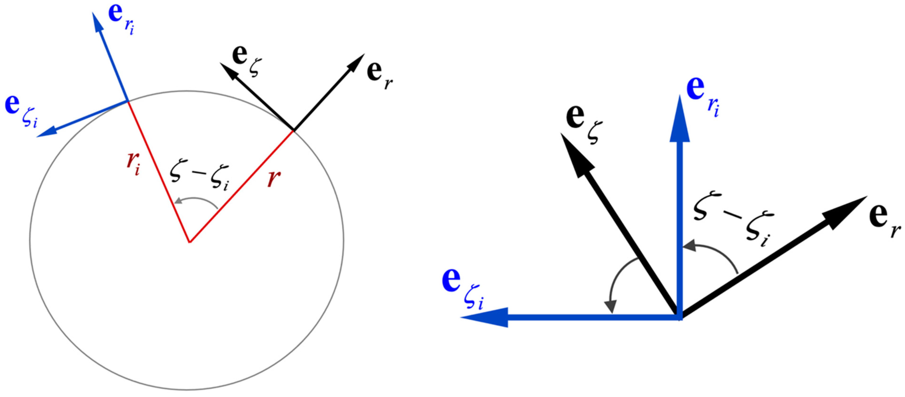
where e k are the unit vectors. Relationship (34), which was also taken into account in (23), is illustrated in Figure 2.
The integration in (33) over the plasma yields ψ p l . Naturally, with the same operation over the wall and over the external conductors, the problem would be completely solved. However, this would be a redundant work and, moreover, with a loss of generality, since, as shown above, ψ e x t ψ b can be found without prescription of the external currents. Besides, the part of ψ b created by the currents in the e c windings can be considered as known. In a static configuration, ψ ˙ b e c determines the toroidal voltage
U = 2 π r E ζ = ψ ˙ b .
During thermal quenches in a tokamak, a spike in U is observed at a constant ψ ˙ b e c [54,55]. In such and similar cases, ψ ˙ p l serves as an input, and ψ w becomes the main unknown.

3. Expressions for ψ e x t with Account of Boundary Condition (18)

In (33), which is an exact consequence of (28) and (32), the result is determined by the density of the toroidal current flowing in v . In the plasma, j ζ may be only roughly evaluated. The particular distribution of the currents in the external conductors is not essential because only their integral effect matters in the task. This implies that j ζ is not a good characteristic, and we should consider possible transformation.
With account of (16), for the combination in (33) we obtain
2 π μ 0 r j ζ G = div ( ψ G r 2 G ψ r 2 ) ψ div G r 2 ,
which is valid where G is a harmonic function without singularities. Within each of the conductors v , the operator in (16) retains only the eigenfunction ψ v , but the presence of the total flux ψ = ψ p l + ψ e c + ψ w in (16) and (36) is convenient for application of the boundary condition ψ = ψ b at S p l .
Outside the region v , that is at r r i , the last term in (36) is zero. Then (33) turns into
ψ v = v ψ i G G i ψ 2 π r i 2 d S i ,
where d S i is the outwardly oriented element of the boundary v of the closed toroidal region v . Hereinafter, the differentiation under the integral is performed with respect to the variable r i .
Selecting the integration surface to be the plasma boundary v = S p l , in order to find ψ p l outside the plasma, we must take into account condition (18) on S p l . Then only one of the two terms in (37) will survive because
p l ψ i G r i 2 d S p l = ψ b p l div i i G r i 2 | r r d r i = 0 ,
see (26). Finally (37) reduces to
ψ p l = p l G i ψ n p l 2 π r i 2 2 π r i d p l = 2 π p l G B d l p l ,
where we use the notation introduced in (21) and the relation n p l ψ = 2 π r B τ p l . Let us recall that equality (39) is valid only for r outside the plasma. It is obtained by the identical transformation of (33) with account of (18) and (26) and therefore determines the function ψ p l completely.
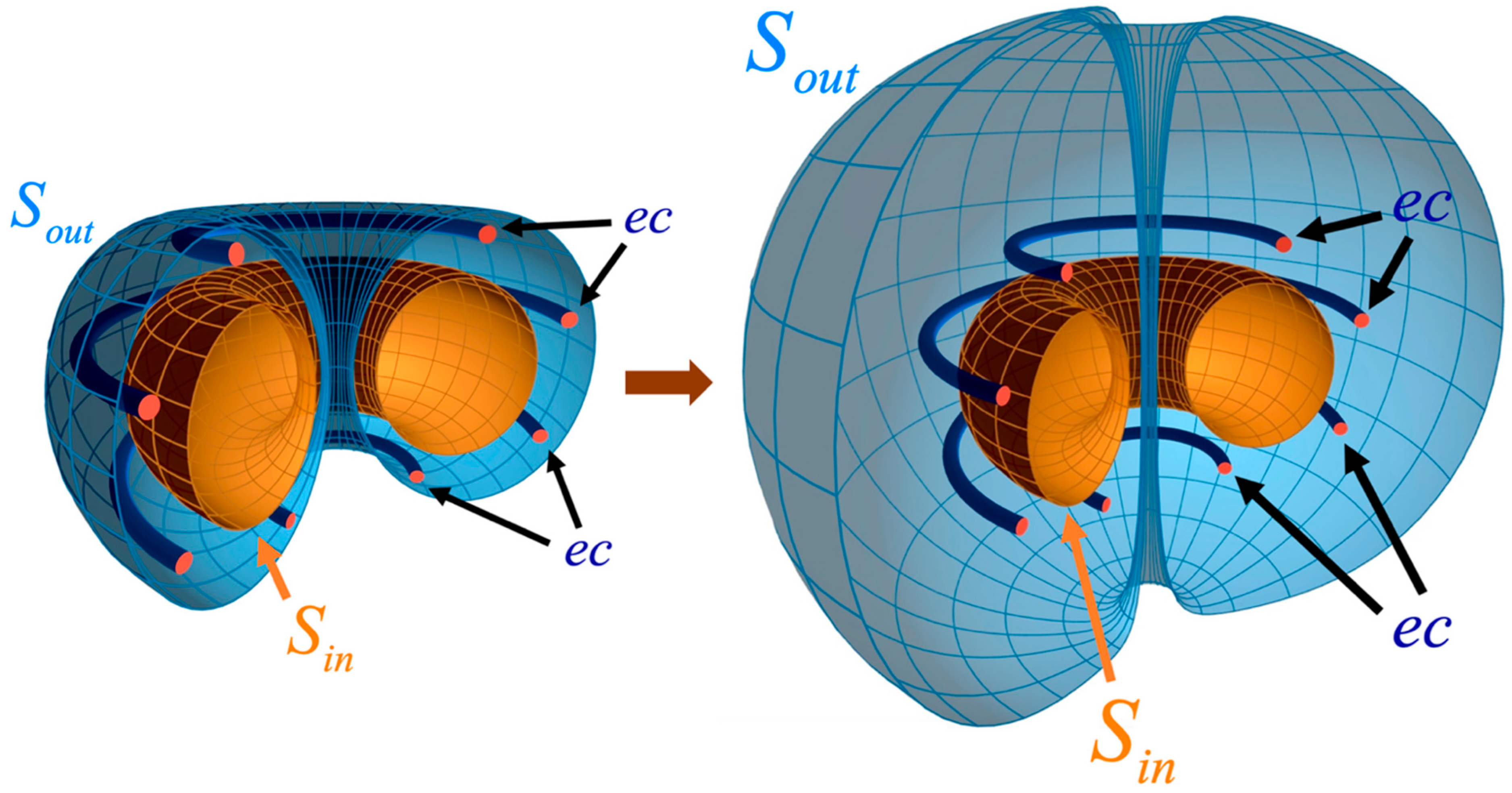
An integral similar to (39) will also appear when calculating ψ e x t , but it will not be the only one in the final expression. This is so because the wall with currents contributing to ψ e x t is a toroidal shell, and we have to find ψ w inside it. The same can be said about the currents in the poloidal windings. In these two cases, when finding ψ v by formula (37), it is necessary to introduce two toroidal shells, the inner S i n and the outer S o u t ones. Then at r r i , i.e., for either r inside the torus S i n , or outside S o u t , from (37) we obtain
ψ e x t = i n [ ψ , G ] 2 π r i 2 d S i n + I o u t ,
where the identical integral over the outer surface S o u t is denoted I o u t , and
[ α , β ] α ( r v ) i β ( r ) β ( r ) i α ( r v )
is a function of three variables r v , r and r i (the latter is not shown). The minus in (40) appears because d S i n is oriented outward the torus i n .
The value of I o u t cannot depend on the shape S o u t , because this surface encloses the considered currents from the outside. It can be transformed into a sphere, as shown in Figure 3, with subsequent transition to the limit | r i | . Then it is easy to show that I o u t = 0 . Indeed, at a large distance from the current-carrying elements (plasma, wall, poloidal coils), they can be considered as thin rings. Therefore, the magnetic flux generated by each of the subsystems far from the plasma can be described by the approximate expression
ψ v ( r ) L v j v ,
where the function L v 2 π μ 0 G ( r v , r ) has the dimension of inductance, and r v is the radius vector of the conductor v . Then the combination under the integral I o u t will be proportional to [ G , G ] . Note that (42) is a direct consequence of (33) for a current loop; this is a well-known classical result [31,33].
To estimate [ G , G ] for | r i | | r | , we use the expansion
1 | r r i | = 1 r 2 + r i 2 2 r r i 1 | r i | ( 1 + r r i | r i | 2 + 3 ( r r i ) 2 | r | 2 | r i | 2 2 | r i | 4 ) ,
where the corrections in | r | / | r i | are retained up to the second order. When (43) is substituted into (22), the nonzero contribution arises only from the terms with cos ( ζ ζ i ) in r r i , see (23). The approximate equality
G ( r , r i ) r i 2 r 2 4 | r i | 3 ( 1 + 3 z z i | r i | 2 ) ,
applicable at | r i | | r | , is also obtained by direct transformation of G in the form (24) for small
k 2 4 r r i r i 2 ( 1 + 2 r r i + z z i r i 2 ) .
In (41), the operator i acts only on r i and z i , therefore
[ G , G ] = [ g 0 ( r v ) , g 1 ( r ) ] + [ g 1 ( r v ) , g 0 ( r ) ] ,
since [ g 0 ( r v ) , g 0 ( r ) ] = [ g 1 ( r v ) , g 1 ( r ) ] = 0 , where g 0 = r 2 f ( r i ) and g 1 = r 2 z h ( r i ) are the two parts of G in (44). Substitution of these g 0 and g 1 into the right-hand side of (46) turns it into r v 2 r 2 ( z z v ) [ f , h ] , and
[ f , h ] = 3 f 2 i z i r i 2 .
Then, for | r i | | r | we obtain for the integrand in I o u t :
[ ψ , G ] 2 π r i 2 = 3 μ 0 16 π r 2 m z v ( z z v ) r i 2 | r i | 6 i z i | r i | 2 ,
where the higher corrections in | r | / | r i | are omitted. Here m z v = π r v 2 J v is the projection of the magnetic moment of the ring with current J v on the vertical axis z . When | r i | , the value (48) decreases as 1 / | r i | 6 , while the area of the sphere S o u t increases as | r i | 2 , so their product in I o u t is proportional to 1 / | r i | 4 . Therefore, I o u t must be zero.
To describe the external magnetic field in the plasma region, in (40) with I o u t = 0 the vector r should be chosen inside the torus S i n . If we take S i n = S p l , then the integral with ψ is transformed similarly to (39), but now it will enter with the opposite sign.
With such r the integral with ψ is also simplified, since ψ = ψ b = c o n s t at the plasma boundary. However, in this case, instead of (38), we obtain
p l ψ i G r i 2 d S p l = ψ b p l div i i G r i 2 | r V p l d r i = 2 π ψ b .
Here the singularity of the function G is accounted for. It is explicitly shown in (26) and leads to (21) with the step function η p l ( r ) defined by (20), since
1 2 π p l div G r 2 d r = η p l ( r ) .
Thus, for S i n = S p l and r inside S p l , equality (40) reduces to
ψ e x t = ψ b + p l G i ψ 2 π r i 2 n p l d S p l = ψ b 2 π p l G B d l p l .
The choice S i n = S p l allows to simplify maximally the final expression and bring it to the form (39). Despite their similarity, we note two fundamental differences. First, they are applicable in different areas: equality (39) is valid outside the plasma, while (51) only inside. Secondly, from (39) we obtain the full value of ψ p l , but (51) provides only ψ e x t ψ b with an unknown constant ψ b .
The uncertainty with ψ b in (51) may seem unexpected, because in both cases the calculations started with the same formula (33), which reduces to (37) and then to (40). The form of the equations does not affect the appearance or disappearance ψ b . The main difference arises when the terms with ψ i G are integrated, see (38) and (49). It is clear that the key role is played by the boundary condition (18), which leads to a simplification when S i n = S p l . For any other S i n and r outside the torus S i n in the first case, but inside S i n in the second one, the expressions for ψ v would contain the term with unknown ψ ( r ) on S i n , e.g., Equation (16) in [52]. A similar situation arises in the theory of stellarators when B n 0 on S i n , see Equation (4.18) in [22].
In addition to prescription of ψ on S i n (for example, as now by an indefinite constant ψ b ) the fundamentally important are the applicability limitations in our final formulas. The original (28) and (33) were not constrained, so the integration there also includes the point r = r i with the singularity of the function G . This gives an additional flux–currents relation. It is linear and in the simplest case is expressed as (42), which is an exact equality for a ring conductor. In calculations, the wall is often represented as a set of such conductors [6,7,8,12,13,26,27,51,56,57,58,59,60,61,62,63,64]. Then one has to calculate the induced current in each of them and make summation of L v J v over the entire set. The size of this block of calculations necessary for closing the evolutionary equilibrium problem differs from case to case. For example, the wall is prescribed by two ring conductors in [26,27], by 50 for each of the two ITER walls in [6], by 77 in T-15MD in [12], by 218 in DIII-D in [57], by 830 in EAST in [63]. It is clear that the segmentation into 830 elements is better than into 50. In the latter variant, the irregularities are visible on the calculated current distribution [6]. Meanwhile, it was established [59] that the response of the ITER vacuum chamber to VDE is well described by only three modes, and our consideration shows that to calculate the induced current in the wall by using formula (15), it is sufficient to add to the equilibrium solutions (6) or (21) a single constant ψ b ( t ) . It remains undefined in (21) due to the incompleteness of the description, in which the matching to the internal solution is properly made, but a part of the information on the flux-current relations has not yet been accounted for.
Both equalities (39) and (51) can be written in a single compact form (21). Its formal derivation was given in [14], where operations with G were performed as with a generalized function. Here, except for (20), it was assumed that r r i , and this ruled out the appearance of singularities. In this case, the main fact is that for any calculation method with a given total magnetic field B on S p l , with boundary condition (8) and its consequence (18), the function ψ p l can be determined completely, but ψ e x t only up to a constant.
The starting point in both cases is equality (33), which, with the help of (12) and (16), reduces to (39). The latter, in contrast to (33), gives the solution not through the source, but through the boundary conditions. These two ways of finding the magnetic field are well known in electrodynamics [31,32,33,65]. Here their implementation is shown in application to tokamaks under constraint (18).

4. The Evolution Equation for ψ w

Equality (33) gives the full value of ψ v . The unknown in the evolutionary problem is ψ w . Taking into account (14) and (15), for this function we obtain
ψ w ( r ) = μ 0 w σ ψ ˙ G d S w r i .
If the wall is treated as a thin shell with thickness d w ( w ) , we have
d S w d r i d z i d w d w ,
where d w is the length element of the wall cross-section.
In a stationary state, ψ ˙ p l = ψ ˙ w = 0 , but ψ w = ψ 0 w 0 due to the presence of the toroidal electric field created by external sources through ψ ˙ e c = ψ ˙ 0 e c 0 . We are interested in the increment δ ψ w = ψ w ψ 0 w , for which, in the thin wall approximation, (52) gives
δ ψ w = μ 0 t w σ d w ψ p l + δ ψ e c + δ ψ w r i G d w .
This single equation with / t is sufficient to close the evolution problem on the basis of the standard theory of plasma equilibrium.
In the steady state, δ ψ w = 0 , which is the initial condition at t = 0 for (54). It would remain zero at ψ ˙ p l + δ ψ ˙ e c = 0 , which requires the equilibrium control system to accurately compensate for the changes generated by the plasma. This is not always possible, at least because of insufficient response speed. Often, when fast processes such as CQ or TQ and the related plasma motions are modelled, the external control field is assumed to be constant, so that δ ψ ˙ e c = 0 . Then the wall reaction is determined only by the driver ψ ˙ p l . The function ψ p l itself is always determined by the integral (39) over the plasma boundary, which is mathematically similar to that present in (54).
Reduction in (54) for a large aspect ratio tokamak with circular plasma and wall cross-sections was given in [14]. One of the consequences of (54) in such a geometry is the equation
J w = τ w 0 d d t [ J + J w + ψ 0 e c ( b w , t ) L w ]
for the net current J w induced in the wall with time constant
τ w 0 τ w L w μ 0 R w = τ w ( ln 8 R w b w 2 ) .
Here
τ w μ 0 σ b w d w
is the resistive wall time, which also naturally arises in the RWM theory [48,49,50], and b w is the wall minor radius. Equation (55) corresponds to the zeroth harmonic of δ ψ w . Accounting for the toroidicity in (54) gives an equation for the cosine component of j ζ w or for d Δ b / d t , see (110) in [14].
In this example, the description of ψ w was made by means of two eigenfunctions. Let us recall the encouraging finding that only three were sufficient for the ITER tokamak [59]. An example of analytical approximation of ψ by three harmonics for a finite plasma elongation was given in [30]. The results of [30], the scheme for solving the equation for ψ w described in [14], and the conclusions of [59] provide the necessary basis for extending equilibrium models to evolutionary problems, including those with VDE.
Equality (54) comes from (33) for j ζ w uniform across the wall. Therefore, it is applicable for describing events that are not accompanied by the skin effect in the wall. These include the typical disruptions in tokamaks, the duration of which is a few or tens of milliseconds [66,67,68,69,70,71]. If, in contrast, the initial perturbation is jump-like, then the wall response must be instantaneous, but the subsequent evolution will inevitably obey Equation (54). The predictions based on (54) can be tested against the magnetic measurements. For diagnostic applications, we note that the constant τ w 0 in (55) arising from (54) determines the exponential decay rate of the wall net current J w . For a circular wall with
j ζ w = m = 0 j m cos m θ ,
where θ is the poloidal angle, the decay time for each harmonic depends on m approximately as τ w / m [72,73]. This is also consistent with the results of numerical calculations in [59,74], where the walls were non-circular.
For an arbitrary wall shape, the resistive time constants τ m for the eigenmode m must be found from the equation
δ ψ m w = τ w τ m w δ ψ m w G r i d w b w .
Here it was assumed that σ = c o n s t , and b w is introduced as a measure of minor radius (also included in the τ w definition). Similar integrals for an elliptic contour and m 2 were calculated analytically in [30].
The numerical results in [59,74] imply that a few solutions to Equations (59) will be sufficient for describing the redistribution and decay of the current in the toroidal wall after the initial perturbation on the way to the state with ψ ˙ p l + δ ψ ˙ e c = 0 . In this case, a large integral force on the wall may appear during the relaxation stage [5]. This effect was confirmed in numerical calculations [7,46,74].

5. Conclusions

Even in such fast processes as disruptions, the dynamically changing shape and position of the plasma must obey equilibrium equation (2), in which the magnetic field B , in addition to B p l and B e c , also contains the field B w created by the currents in the vacuum vessel wall. For such and other evolutionary problems with characteristic times comparable to τ w , the standard formulation must be supplemented by an equation for B w . The inductive excitation of the wall current is taken into account in many codes, see [1,6,7,8,9,10,11,13,44,45,46,51,56,57,58,59,60,61,62,63]. Here the basis is prepared for applications in combination with the results of the analytical equilibrium theory.
The separation of B on B p l and B e x t by general equality (19) could allow to find B w = B e x t B e c for a given external field B e c . This requires the plasma boundary S p l to be prescribed in advance, but it easily moves and deforms and must be considered unknown. The presented analytics shows that, for extension of the equilibrium theory on such dynamic events, the knowledge of ψ b is needed. This is the minimal requirement for self-consistent calculation of E . The equilibrium equations contain only ψ , which explains why ψ b cannot be found from (19) or equivalent formulations such as virtual casing principle. In the standard equilibrium approaches, the total poloidal magnetic flux at the boundary ψ b is an input quantity of the user [75]. Being treated as an insignifcant constant [17,19,20,21,58,75,76,77,78,79,80,81,82,83], sometimes “for convenience” it is replaced by zero [17,20,78,79,82]. Such boundary conditions with enforced ψ b = 0 are especially confusing in the intended applications to the evolving plasma (first of all to cover CQs) where an additional block of calculations becomes necessary.
If the vacuum vessel wall is the main passive element, the extension is covered by Equation (54). Examples of the analytical operations with this equation for the plasma and wall with circular cross-sections were given in [14,73]. The technique for calculating an integral similar to that in (54) over an elliptic contour is described in detail in [30] though it was done with a given integrand.
Now this can serve as a ready basis for the next step: construction of the analytical model with three vessel modes for the ITER-like geometry. The development of such a model is motivated by the mentioned discovery in [59] perfectly illustrated by numerical calculations. Here we formulated the minimal necessary additions to standard equilibrium schemes presented and reviewed in [14,30]. The 2D equations in a general form are universally good for numerical and analytical approaches. The reduction to 1D equations with account of the shape effects is a separate task.
The results of [30] demonstrate the solvability of the external part of the equilibrium problem for a non-circular plasma with an arbitrary current profile. The main difficulties in this case appear only in operations with the Green’s function G , but these are much simpler than working with series containing the associated Legendre functions [17,20,21,24,72,81], the Meijer G-functions [78,79], modified Mathieu functions [84] in the toroidal coordinates, and systems of equations with a large set of matrices [85]. Additional simplifications arise if we take into account relation (22) of G with the fundamental solution | r r i | 1 of the Laplace equation.
Equality (59) shows that the velocity of the plasma radial motion after the perturbation is determined by τ w / 2 . This result was obtained for a circular wall [14]. To find the VDE velocity, calculations with non-circular plasma are needed, as in [30]. Another application of the developed theory will be the evaluation of the forces on the wall during disruptions.

Author Contributions

Investigation, V.D.P. and N.V.C. All authors have read and agreed to the published version of the manuscript.

Funding

This research received no external funding.

Institutional Review Board Statement

Not applicable.

Informed Consent Statement

Not applicable.

Data Availability Statement

Not applicable.

Acknowledgments

The authors are grateful to Yu V Gribov, N V Ivanov and S V Konovalov for continuous support, and to the experts of the ITPA Topical Group on MHD Stability for fruitful discussions.

Conflicts of Interest

The authors declare no conflict of interest.

References

  1. Villone, F.; Ramogida, G.; Rubinacci, G. Electromagnetic disruption analysis in IGNITOR. Fusion Eng. Des. 2015, 93, 57–68. [Google Scholar] [CrossRef]
  2. Li, X.; Zakharov, L.E.; Galkin, S.A. Adaptive Grids in Simulations of Toroidal Plasma Starting from Magneto-Hydrodynamic Equilibrium. Plasma Sci. Technol. 2015, 17, 97–104. [Google Scholar] [CrossRef]
  3. Zakharov, L.E.; Li, X. Tokamak magneto-hydrodynamics and reference magnetic coordinates for simulations of plasma disruptions. Phys. Plasmas 2015, 22, 062511. [Google Scholar] [CrossRef]
  4. Pustovitov, V.D. Radial force on the vacuum chamber wall during thermal quench in tokamaks. Plasma Phys. Rep. 2015, 41, 952–960. [Google Scholar] [CrossRef]
  5. Pustovitov, V. General approach to the problem of disruption forces in tokamaks. Nucl. Fusion 2015, 55, 113032. [Google Scholar] [CrossRef]
  6. Khayrutdinov, R.R.; Lukash, V.; Pustovitov, V.D. Local and integral forces on the vacuum vessel during thermal quench in the ITER tokamak. Plasma Phys. Control. Fusion 2016, 58, 115012. [Google Scholar] [CrossRef]
  7. Pustovitov, V.; Rubinacci, G.; Villone, F. On the computation of the disruption forces in tokamaks. Nucl. Fusion 2017, 57, 126038. [Google Scholar] [CrossRef]
  8. Portone, A. Force scaling for n = 0 RWMs. Nucl. Fusion 2019, 59, 024002. [Google Scholar] [CrossRef]
  9. Sovinec, C.R.; Bunkers, K.J. Effects of asymmetries in computations of forced vertical displacement events. Plasma Phys. Control. Fusion 2019, 61, 024003. [Google Scholar] [CrossRef]
  10. Yanovskiy, V.; Isernia, N.; Pustovitov, V.; Villone, F.; Abate, D.; Bettini, P.; Chen, S.; Havlicek, J.; Herrmann, A.; Hromadka, J.; et al. Comparison of approaches to the electromagnetic analysis of Compass-U vacuum vessel during fast transients. Fusion Eng. Des. 2019, 146, 2338. [Google Scholar] [CrossRef]
  11. Isernia, N.; Pustovitov, V.D.; Villone, F.; Yanovskiy, V. Cross-validation of analytical models for computation of disruption forces in tokamaks. Plasma Phys. Control. Fusion 2019, 61, 115003. [Google Scholar] [CrossRef]
  12. Dubrov, M.L.; Lukash, V.E.; Khayrutdinov, R.R.; Dokuka, V.N. Analysis of Electromagnetic Forces in Tokamak Vacuum Chamber due to Induced Poloidal Current after Thermal Quench. Phys. At. Nucl. 2020, 83, 1058. [Google Scholar] [CrossRef]
  13. Khayrutdinov, R.R.; Lukash, V.E.; Pustovitov, V.D. Analysis of Electromagnetic Loads on the Vacuum Vessel during Thermal Quench in the TRT Tokamak. Plasma Phys. Rep. 2021, 47, 1128. [Google Scholar] [CrossRef]
  14. Pustovitov, V.D. Extension of Shafranov’s Equilibrium Theory to the Description of Current Quenches Affected by Resistive Wall Dissipation in Tokamaks. Plasma Phys. Rep. 2019, 45, 1114. [Google Scholar] [CrossRef]
  15. Shafranov, V.D. Equilibrium of a toroidal plasma in a magnetic field. J. Nucl. Energy. C 1963, 5, 251. [Google Scholar] [CrossRef]
  16. Mukhovatov, V.; Shafranov, V. Plasma equilibrium in a Tokamak. Nucl. Fusion 1971, 11, 605. [Google Scholar] [CrossRef]
  17. Zakharov, L.E.; Shafranov, V.D. Equilibrium of Current-Carrying Plasmas in Toroidal Configurations. In Reviews of Plasma Physics; Leontovich, M.A., Kadomtsev, B.B., Eds.; Consultants Bureau: New York, NY, USA, 1986; Volume 11, p. 153. [Google Scholar]
  18. Shafranov, V.D. Plasma Equilibrium in a Magnetic Field. In Reviews of Plasma Physics; Leontovich, M.A., Ed.; Consultants Bureau: New York, NY, USA, 1966; Volume 2, p. 103. [Google Scholar]
  19. Freidberg, J.P. Ideal Magnetohydrodynamics; Plenum: New York, NY, USA, 1987. [Google Scholar]
  20. Takeda, T.; Tokuda, S. Computation of MHD equilibrium of tokamak plasma. J. Comput. Phys. 1991, 93, 1. [Google Scholar] [CrossRef]
  21. Braams, B.J. The interpretation of tokamak magnetic diagnostics. Plasma Phys. Control. Fusion 1991, 33, 715–748. [Google Scholar] [CrossRef]
  22. Pustovitov, V.D. Theoretical Principles of the Plasma-Equilibrium Control in Stellarators. In Reviews of Plasma Physics; Kadomtsev, B.B., Shafranov, V.D., Eds.; Consultants Bureau: New York, NY, USA, 2000; Volume 21. [Google Scholar]
  23. Wesson, J.A. Tokamaks, 3rd ed.; Oxford University Press: Oxford, UK, 2004. [Google Scholar]
  24. Goedbloed, J.P.; Keppens, R.; Poedts, S. Advanced Magnetohydrodynamics with Applications to Laboratory and Astrophysical Plasmas; Cambridge University Press: Oxford, UK, 2010. [Google Scholar]
  25. Lazarus, E.; Lister, J.; Neilson, G. Control of the vertical instability in tokamaks. Nucl. Fusion 1990, 30, 111. [Google Scholar] [CrossRef]
  26. Kiramov, D.I.; Breizman, B.N. Model of vertical plasma motion during the current quench. Phys. Plasmas 2017, 24, 100702. [Google Scholar] [CrossRef]
  27. Pfefferlé, D.; Bhattacharjee, A. Algebraic motion of vertically displacing plasmas. Phys. Plasmas 2018, 25, 022516. [Google Scholar] [CrossRef]
  28. Bardsley, O.P.; Hender, T.C. On the axisymmetric stability of tokamaks with ferromagnetic walls. Phys. Plasmas 2020, 27, 102508. [Google Scholar] [CrossRef]
  29. Porcelli, F.; Yolbarsop, A.; Barberis, T.; Fitzpatrick, R. Resonant Axisymmetric Modes. J. Phys. Conf. Ser. 2021, 1785, 012004. [Google Scholar] [CrossRef]
  30. Pustovitov, V.D.; Chukashev, N.V. Analytical Solution to External Equilibrium Problem for Plasma with Elliptic Cross Section in a Tokamak. Plasma Phys. Rep. 2021, 47, 956. [Google Scholar] [CrossRef]
  31. Stratton, J.A. Electromagnetic Theory; McGrow-Hill Book Company, Inc.: New York, NY, USA, 1941. [Google Scholar]
  32. Smythe, W.R. Static and Dynamic Electricity, 3rd ed.; McGraw-Hill: New York, NY, USA, 1968. [Google Scholar]
  33. Jackson, J.D. Classical Electrodynamics, 3rd ed.; Wiley: New York, NY, USA, 1998. [Google Scholar]
  34. Morozov, A.I.; Solov’ev, L.S. The Structure of Magnetic Fields. In Reviews of Plasma Physics; Leontovich, M.A., Ed.; Consultants Bureau: New York, NY, USA, 1966; Volume 2, p. 1. [Google Scholar]
  35. Shafranov, V.; Zakharov, L. Use of the virtual-casing principle in calculating the containing magnetic field in toroidal plasma systems. Nucl. Fusion 1972, 12, 599. [Google Scholar] [CrossRef]
  36. Zakharov, L. Numerical methods for solving some problems of the theory of plasma equilibrium in toroidal configurations. Nucl. Fusion 1973, 13, 595. [Google Scholar] [CrossRef]
  37. Strumberger, E.; Günter, S.; Merkel, P.; Schwarz, E.; Tichmann, C.; Zehrfeld, H.-P. Numerical computation of magnetic fields of two- and three-dimensional equilibria with net toroidal current. Nucl. Fusion 2002, 42, 827. [Google Scholar] [CrossRef]
  38. Hirshman, S.P.; Lazarus, E.A.; Hanson, J.D.; Knowlton, S.F.; Lao, L.L. Magnetic diagnostic responses for compact stellarators. Phys. Plasmas 2004, 11, 595. [Google Scholar] [CrossRef]
  39. Lazerson, S.; Sakakibara, S.; Suzuki, Y. A magnetic diagnostic code for 3D fusion equilibria. Plasma Phys. Control. Fusion 2013, 55, 025014. [Google Scholar] [CrossRef]
  40. Li, X.; Zakharov, L.E.; Drozdov, V.V. Edge equilibrium code for tokamaks. Phys. Plasmas 2014, 21, 012505. [Google Scholar] [CrossRef]
  41. Hanson, J.D. The virtual-casing principle and Helmholtz’s theorem. Plasma Phys. Control. Fusion 2015, 57, 115006. [Google Scholar] [CrossRef]
  42. Sweeney, R.M.; Strait, E.J. Decomposing magnetic field measurements into internally and externally sourced components in toroidal plasma devices. Phys. Plasmas 2019, 26, 012509. [Google Scholar] [CrossRef]
  43. Malhotra, D.; Cerfon, A.J.; O’neil, M.; Toler, E. Efficient high-order singular quadrature schemes in magnetic fusion. Plasma Phys. Control. Fusion 2019, 62, 024004. [Google Scholar] [CrossRef]
  44. Clauser, C.F.; Jardin, S.C.; Ferraro, N. Vertical forces during vertical displacement events in an ITER plasma and the role of halo currents. Nucl. Fusion 2019, 59, 126037. [Google Scholar] [CrossRef]
  45. Krebs, I.; Artola, F.J.; Sovinec, C.R.; Jardin, S.C.; Bunkers, K.J.; Hoelzl, M.; Ferraro, N.M. Axisymmetric simulations of vertical displacement events in tokamaks: A benchmark of M3D-C1, NIMROD, and JOREK. Phys. Plasmas 2020, 27, 022505. [Google Scholar] [CrossRef]
  46. Artola, F.; Loarte, A.; Hoelzl, M.; Lehnen, M.; Schwarz, N.; The JOREK Team. Non-axisymmetric MHD simulations of the current quench phase of ITER mitigated disruptions. Nucl. Fusion 2022, 62, 056023. [Google Scholar] [CrossRef]
  47. Chance, M.S. Vacuum calculations in azimuthally symmetric geometry. Phys. Plasmas 1997, 4, 2161. [Google Scholar] [CrossRef]
  48. Pustovitov, V.D. General formulation of the resistive wall mode coupling equations. Phys. Plasmas 2008, 15, 072501. [Google Scholar] [CrossRef]
  49. Chu, M.S.; Okabayashi, M. Stabilization of the external kink and the resistive wall mode. Plasma Phys. Control. Fusion 2010, 52, 123001. [Google Scholar] [CrossRef]
  50. Pustovitov, V.D. Plasma stability theory including the resistive wall effects. J. Plasma Phys. 2015, 81, 905810609. [Google Scholar] [CrossRef]
  51. Jardin, S.; Pomphrey, N.; Delucia, J. Dynamic modeling of transport and positional control of tokamaks. J. Comput. Phys. 1986, 66, 481. [Google Scholar] [CrossRef]
  52. Lackner, K. Computation of ideal MHD equilibria. Comput. Phys. Commun. 1976, 12, 33. [Google Scholar] [CrossRef]
  53. Pustovitov, V.D. Resolution of the paradox discovered by Freidberg in the Shafranov’s theory on plasma equilibrium. Phys. Plasmas 2020, 27, 102503. [Google Scholar] [CrossRef]
  54. Wesson, J.; Ward, D.; Rosenbluth, M. Negative voltage spike in tokamak disruptions. Nucl. Fusion 1990, 30, 1011. [Google Scholar] [CrossRef]
  55. Takei, N.; Nakamura, Y.; Tsutsui, H.; Yoshino, R.; Kawano, Y.; Ozeki, T.; Tobita, K.; Tsuji-Iio, S.; Shimada, R.; Jardin, S.C. Numerical simulation on current spike behaviour of JT-60U disruptive plasmas. Plasma Phys. Control. Fusion 2004, 46, 1815. [Google Scholar] [CrossRef]
  56. Khayrutdinov, R.; Lukash, V. Studies of Plasma Equilibrium and Transport in a Tokamak Fusion Device with the Inverse-Variable Technique. J. Comput. Phys. 1993, 109, 193. [Google Scholar] [CrossRef]
  57. Sayer, R.; Peng, Y.-K.; Jardin, S.; Kellman, A.; Wesley, J. TSC plasma halo simulation of a DIII-D vertical displacement episode. Nucl. Fusion 1993, 33, 969. [Google Scholar] [CrossRef]
  58. Galkin, S.; Ivanov, A.; Medvedev, S.; Poshekhonov, Y. Comparison of tokamak axisymmetric mode growth rates from linear MHD and equilibrium evolution approaches. Nucl. Fusion 1997, 37, 1455. [Google Scholar] [CrossRef]
  59. Portone, A. The stability margin of elongated plasmas. Nucl. Fusion 2005, 45, 926. [Google Scholar] [CrossRef]
  60. Miyamoto, S.; Isayama, A.; Bandyopadhyay, I.; Jardin, S.; Khayrutdinov, R.; Lukash, V.; Kusama, Y.; Sugihara, M. Intercode comparison benchmark between DINA and TSC for ITER disruption modelling. Nucl. Fusion 2014, 54, 083002. [Google Scholar] [CrossRef]
  61. Qiu, Q.; Xiao, B.; Guo, Y.; Liu, L.; Xing, Z.; Humphreys, D. Simulation of EAST vertical displacement events by tokamak simulation code. Nucl. Fusion 2016, 56, 106029. [Google Scholar] [CrossRef]
  62. Jana, S.; Pradhan, S.; Dhongde, J.; Masand, H.; SST-1 Team. Vessel eddy current characteristics in SST-1 tokamak. Fusion Eng. Des. 2016, 112, 380. [Google Scholar] [CrossRef]
  63. Qiu, Q.; Guo, Y.; Gao, X.; Huang, J.; Sun, H.; Li, J.; Xiao, B.; Chen, D.; Luo, Z. Simulation of hot VDE disruption in EAST by using the TSC code. Fusion Eng. Des. 2020, 150, 111358. [Google Scholar] [CrossRef]
  64. Kumar, R.; Jha, S.; Aich, S.; Macwan, T.; Kumawat, D.; Tanna, R.; Ghosh, J.; Patel, K.; Jadeja, K. Estimation of vacuum vessel time-constant in ADITYA-U tokamak. Fusion Eng. Des. 2022, 177, 113055. [Google Scholar] [CrossRef]
  65. Morse, P.; Feshbach, H. Methods of Theoretical Physics; McGraw-Hill: New York, NY, USA, 1953. [Google Scholar]
  66. ITER Physics Expert Group on Disruptions, Plasma Control and MHD, ITER Physics Basis Editors. ITER EDA Chapter 3: MHD stability, operational limits and disruptions. Nucl. Fusion 1999, 39, 2251. [Google Scholar] [CrossRef]
  67. Hender, T.; Wesley, J.; Bialek, J.; Bondeson, A.; Boozer, A.; Buttery, R.; Garofalo, A.; Goodman, T.; Granetz, R.; Gribov, Y.; et al. Chapter 3: MHD stability, operational limits and disruptions. Nucl. Fusion 2007, 47, S128. [Google Scholar] [CrossRef]
  68. Riccardo, V.; Arnoux, G.; Cahyna, P.; Hender, T.C.; Huber, A.; Jachmich, S.; Kiptily, V.; Koslowski, R.; Krlin, L.; Lehnen, M.; et al. JET disruption studies in support of ITER. Plasma Phys. Control. Fusion 2010, 52, 124018. [Google Scholar] [CrossRef]
  69. Pautasso, G.; Giannone, L.; Gruber, O.; Herrmann, A.; Maraschek, M.; Schuhbeck, K.H.; The ASDEX Upgrade Team. The halo current in ASDEX Upgrade. Nucl. Fusion 2011, 51, 043010. [Google Scholar] [CrossRef]
  70. Myers, C.; Eidietis, N.; Gerasimov, S.; Gerhardt, S.; Granetz, R.; Hender, T.; Pautasso, G.; Contributors, J. A multi-machine scaling of halo current rotation. Nucl. Fusion 2017, 58, 016050. [Google Scholar] [CrossRef]
  71. Gerasimov, S.N.; Abreu, P.; Artaserse, G.; Baruzzo, M.; Buratti, P.; Carvalho, I.S.; Coffey, I.H.; De La Luna, E.; Hender, T.C.; Henriques, R.B.; et al. Overview of disruptions with JET-ILW. Nucl. Fusion 2020, 60, 066028. [Google Scholar] [CrossRef]
  72. Dialetis, D.; Len, L.K.; Golden, J.; Kapetanakos, C.A. Diffusion of magnetic fields in a toroidal conducting shell of circular cross section. J. Appl. Phys. 1991, 69, 1813. [Google Scholar] [CrossRef]
  73. Pustovitov, V.D. Reaction of the toroidal resistive wall on the magnetic field variations in tokamak-like systems. Phys. Plasmas 2018, 25, 062510. [Google Scholar] [CrossRef]
  74. Yanovskiy, V.; Isernia, N.; Pustovitov, V.; Scalera, V.; Villone, F.; Hromadka, J.; Imrisek, M.; Havlicek, J.; Hron, M.; Panek, R. Global forces on the COMPASS-U wall during plasma disruptions. Nucl. Fusion 2021, 61, 096016. [Google Scholar] [CrossRef]
  75. Abate, D.; Bettini, P. An inverse equilibrium tool to define axisymmetric plasma equilibria Plasma Phys. Control. Fusion 2019, 61, 105016. [Google Scholar] [CrossRef]
  76. Itagaki, M.; Fukunaga, T. Boundary element modelling to solve the Grad–Shafranov equation as an axisymmetric problem. Eng. Anal. Bound. Elements 2006, 30, 746–757. [Google Scholar] [CrossRef]
  77. Faugeras, B.; Heumann, H. FEM-BEM coupling methods for Tokamak plasma axisymmetric free-boundary equilibrium computations in unbounded domains. J. Comput. Phys. 2017, 343, 201. [Google Scholar] [CrossRef]
  78. López, O.E.; Guazzotto, L. High-beta analytic equilibria in circular, elliptical, and D-shaped large aspect ratio axisymmetric configurations with poloidal and toroidal flows. Phys. Plasmas 2017, 24, 032501. [Google Scholar] [CrossRef]
  79. López, O.E.; Guazzotto, L. Stability of a tokamak plasma with diffuse toroidal rotation. J. Plasma Phys. 2020, 86, 905860514. [Google Scholar] [CrossRef]
  80. Hole, M.J.; Qu, Z.; Pinches, S.D.; Schneider, M.; Arbina, I.L.; Mantsinen, M.; Sauter, O. The impact of anisotropy on ITER scenarios. Nucl. Fusion 2020, 60, 112010. [Google Scholar] [CrossRef]
  81. Faugeras, B. An overview of the numerical methods for tokamak plasma equilibrium computation implemented in the NICE code. Fusion Eng. Des. 2020, 160, 112020. [Google Scholar] [CrossRef]
  82. Guazzotto, L.; Freidberg, J.P. Simple, general, realistic, robust, analytic tokamak equilibria. Part 1. Limiter and divertor tokamaks. J. Plasma Phys. 2021, 87, 905870303. [Google Scholar] [CrossRef]
  83. Faugeras, B.; Blum, J.; Boulbe, C. First equilibrium reconstruction for ITER with the code NICE. J. Instrum. 2022, 17, C02024. [Google Scholar] [CrossRef]
  84. Goedbloed, J.; Zakharov, L. Helical equilibria of a plasma column with a diffuse current distribution. Nucl. Fusion 1980, 20, 1515. [Google Scholar] [CrossRef]
  85. Hölzl, M.; Merkel, P.; Huysmans, G.T.A.; Nardon, E.; Strumberger, E.; McAdams, R.; Chapman, I.; Günter, S.; Lackner, K. Coupling JOREK and STARWALL codes for non-linear resistive-wall simulations. J. Phys. Conf. Ser. 2012, 401, 012010. [Google Scholar] [CrossRef]
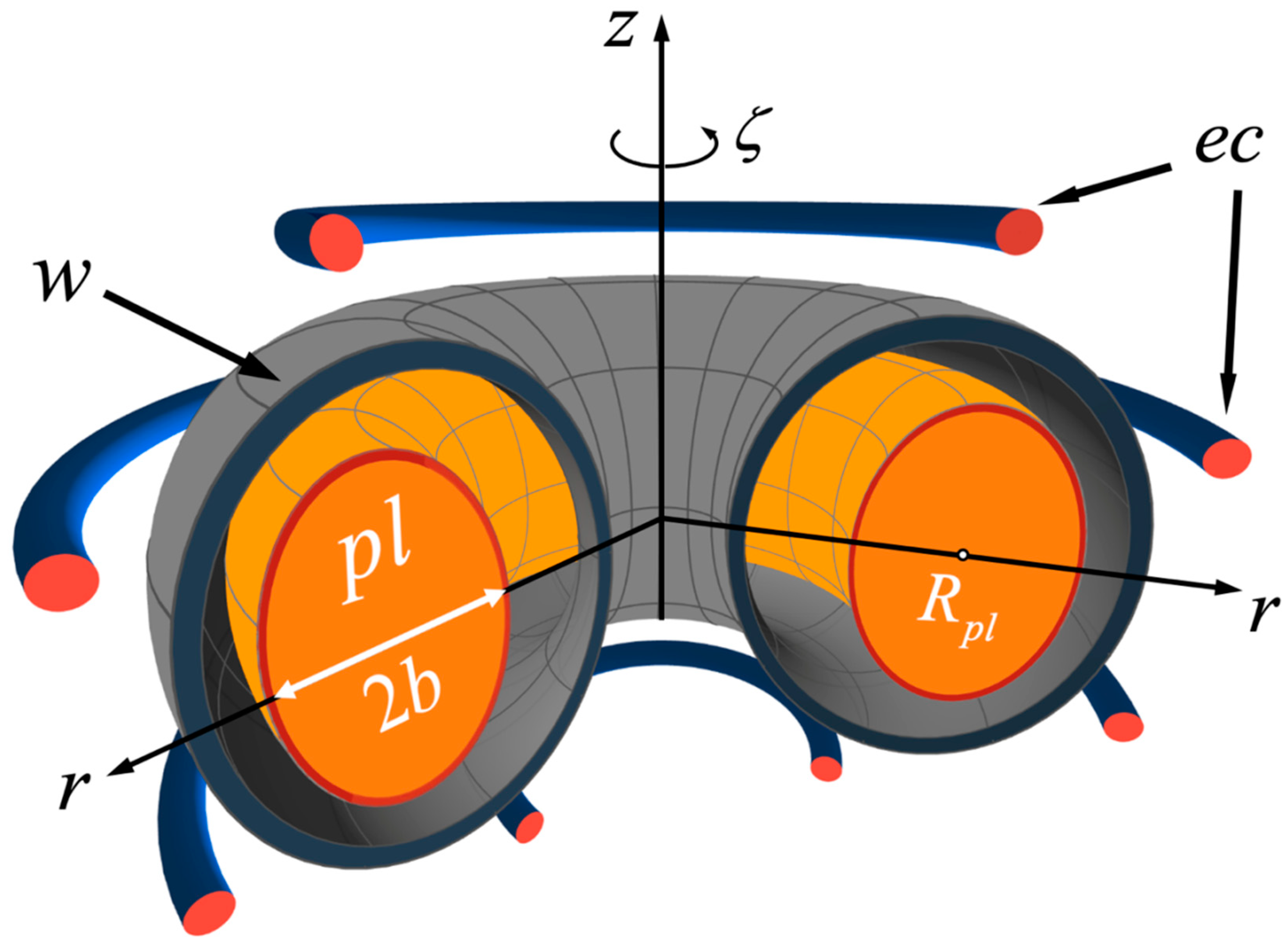
Figure 1. Schematic view of a large aspect-ratio tokamak with vertically elongated plasma of major and minor radii R p l and b , respectively. The plasma is marked as pl, ec corresponds to external coils, and w denotes the wall.
Mathematics 11 01885 g001
Figure 2. Two sets of coordinates and related unit vectors: the radial e r and the toroidal e ζ . The subscript i denotes variables on which the integration is performed, and ζ ζ i is the angle between two basis sets.
Mathematics 11 01885 g002
Figure 3. Surfaces of integration in (40), the inner S i n and the outer S o u t ones. On the right plot, the S o u t torus is transformed into a sphere with a disappearing hole at r = 0 . As in Figure 1, ec means external coils.
Mathematics 11 01885 g003
Disclaimer/Publisher’s Note: The statements, opinions and data contained in all publications are solely those of the individual author(s) and contributor(s) and not of MDPI and/or the editor(s). MDPI and/or the editor(s) disclaim responsibility for any injury to people or property resulting from any ideas, methods, instructions or products referred to in the content.