Abstract
In this paper, an adaptive depth and heading control of an autonomous underwater vehicle using the concept of an adaptive neuro-fuzzy inference system (ANFIS) is designed. The autonomous underwater vehicle dynamics have six degrees of freedom, which are highly nonlinear and time-varying. It is affected by environmental effects such as ocean currents and tidal waves. Due to nonlinear dynamics designing, a stable controller in an autonomous underwater vehicle is a difficult end to achieve. Fuzzy logic and neural network control blocks make up the proposed control design to control the depth and heading angle of autonomous underwater vehicle. The neural network is trained using the back-propagation algorithm. In the presence of noise and parameter variation, the proposed adaptive controller’s performance is compared with that of the self-tuning fuzzy-PID and fuzzy logic controller. Simulations are conducted to obtain the performance of both controller models in terms of overshoot, and the rise time and the result of the proposed adaptive controller exhibit superior control performance and can eliminate the effect of uncertainty.
Keywords:
adaptive neuro-fuzzy inference system; autonomous underwater vehicle; fuzzy logic controller; neural network; self-tuning fuzzy-PID MSC:
68T05; 68U01; 68W50
1. Introduction
Over the past decade, the ocean space has gained importance in the global scenario for its competitive potential in military and economic applications. In this context, the autonomous underwater vehicle [1,2,3] has proven to be the most effective object for underwater activities such as inspection of oil industry pipelines, target search, seabed surface reconstruction, military operation, and so on. The researchers consider it a great challenge to design the controller of the autonomous underwater vehicle because of its eminent nature of dynamism and nonlinearity due to ocean currents, an uncertainty parameter, external disturbances, hydrodynamic forces, etc. The estimated autonomous underwater vehicle parameters have more uncertainty and variation; therefore, the designed controller must be robust and adaptive. Due to nonlinearity, time-varying dynamic characteristics, and disturbances of sea waves and currents, linear and nonlinear control techniques have been developed. Linear controllers such as PID control techniques cannot offer better performance because the dynamic characteristics of an autonomous underwater vehicle are quite complex. The design of an autonomous underwater vehicle’s control system takes into account many factors: stability, robustness, and the ability to change parameters, which itself requires adaptive capability due to sensor noise, disturbances caused by sea currents and waves, and changes in autonomous underwater vehicle dynamics. There are many controller models of autonomous underwater vehicles that have been proposed, including linear controllers such as PID [4], linear quadratic regulators, and linear quadratic Gaussian [5,6]. These controllers have produced better performance when the autonomous underwater vehicle is operating as a linear model. Similarly, some other linear techniques such as linear matrix inequality are used as solutions for fifth-order systems [7]. It determines the global optimal solution numerically effectively and consistently. It can be used to examine the dynamics system for heading and depth plane high-precision control of an autonomous underwater vehicle’s stability [8]. However, linear matrix is feasible for lower-order systems, but for higher-order systems, results become complicated. Due to some uncertainty parameters, the autonomous underwater vehicle faces unexpected errors during underwater motion. The nonlinearity of the system prevents the linear controller from achieving a better outcome. Some of the adaptive techniques such as fuzzy logic controller [9,10,11,12], sliding mode controller [13,14,15], model predictive controller [16,17], adaptive controllers [18,19,20,21,22,23,24,25,26], neural network [27,28,29], and intelligent robust control method [30,31] are widely used for the overshoot reduction for an autonomous underwater vehicle. Further, some authors have addressed techniques that are based on machine learning, such as semi-supervised and supervised learning [32], deep learning [33], and reinforcement learning [34,35], which are employed in autonomous underwater vehicles for better depth control, heading control, and tracking of the desired path. Though the model has time-varying and uncertain parameters, the adaptive controller, which is a nonlinear type used in the autonomous underwater vehicle model, achieves better performance. The controller can adapt itself to the turbulence of wave, current, and changes in weight of the autonomous underwater vehicle. The neural network has some loopholes that hinder the scope of its improvement and has a slow convergence rate with more training time, which is not applicable to fit into many systems. The system should produce a fast response with less overshoot and undershoot than the classical neural network, which cannot accomplish the above requirements. Sliding mode controllers produce chattering on actuators, but it is an appropriate controller design solution for a nonlinear system. By converting the sign function to a saturation function and combining fuzzy logic, the chattering effect can be minimized.
Further, the PID controller is taken for comparison with the proposed techniques. Although PID is a conventional controller still in industrial control, PID control is the most commonly used. PID controller has the advantages of simple structure, good stability, reliable operation, and convenient adjustment and does not need the prerequisite of an accurate system model. When we cannot obtain accurate and precise system modeling, PID control technology is the most appropriate. However, when the controlled object is in complex underwater environment, and the system is nonlinear, the control effect of the PID control method is limited, and it is difficult to meet the precision requirements of the system. To overcome the problems with PID, it is required to tune the parameters of the PID controller. Initially, fuzzy–PID controller or self-tuning fuzzy PID controller (STFPID) is chosen for tuning the PID parameters. However, it is found that the factors of more settling time, more overshoot, and slow response are the demerits of the self-tuning fuzzy-PID controller. To reduce these issues, the authors have taken ANFIS because of its zero percent of steady-state error, superior set point tracking against parameter and external disruption, and reliability.
The main contributions of this paper are highlighted as follows:
- (a)
- In this work, the autonomous underwater vehicle is considered to be the most effective object for underwater activities such as inspection of oil industry pipelines, target search, seabed surface reconstruction, military operation, etc.;
- (b)
- It is a challenging issue to design the controller of the autonomous underwater vehicle because of its eminent nature of dynamism and nonlinearity characteristics;
- (c)
- Therefore, it is required to adapt a technique that must be robust and adaptive, and also, it is necessary to rationally optimize the space motion model of autonomous underwater vehicle so that it can adapt to the complex and have high reliability;
- (d)
- Various linear and nonlinear control techniques have been developed to handle non-linearity, time-varying dynamic characteristics, and disturbances of sea waves and currents;
- (e)
- The PID control techniques cannot offer better performance because the dynamic characteristics of an autonomous underwater vehicle are quite complex;
- (f)
- Self-tuning fuzzy-PID is then considered for the operation of autonomous underwater vehicles. However, the performance is weak in terms of settling time, more overshoot, and slow response. Moreover, acceptable overshoot and oscillations appear because of the consideration of reducing the complexity and difficulty of the controller design process;
- (g)
- In the presence of various uncertain factors, the system with the ANFIS method can adapt to the complex environment and unknown ocean current interference so that the control effect of the controller can remain consistent and has good robustness. The ANFIS controller performed better than other control techniques when hydrodynamic constraints varied.
The performance of the proposed models was compared with other soft computing techniques and was assessed by MATLAB/Simulink.
The rest of the paper is organized as follows: In Section 2, the autonomous underwater vehicle’s mathematical model design is described. In Section 3, the controlling strategies are discussed. Section 4 presents the results of the analysis and simulation study, and Section 5 presents the conclusion.
2. Mathematical Model Design of Autonomous Underwater Vehicle
The autonomous underwater vehicle equation can be designed by considering the following elements: kinematic motion in geometric aspects and rigid body dynamics, which represent the inertia matrix of autonomous underwater vehicle and moments of force caused by the motion of autonomous underwater vehicle. The autonomous underwater vehicle kinematics and dynamics are represented in vector form and explained in Equations (1)–(5). The general movement of the autonomous underwater vehicle in six degrees of freedom is shown in Figure 1, and Table 1 represents six degrees of freedom motions.
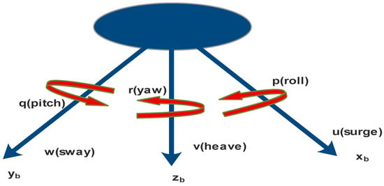
Figure 1.
Motion parameters of the autonomous underwater vehicle.

Table 1.
Six degrees of freedom motions.
Assume the autonomous underwater vehicle’s body is fixed frame, earth is reference frame, and it can be depicted by the following vectors:
where are position and orientation vectors.
The translational and rotational velocities are , and are the total force and moment of the autonomous underwater vehicle in the forward direction, respectively.
The linear velocities during movement of the autonomous underwater vehicle are explained in Equation (6).
where is represented in Equation (7).
where C stands for Cos, and S stands for Sin.
The angular velocity of the autonomous underwater vehicle is shown in Equation (8).
where is represented in Equation (9).
The parameters are obtained from [1,2].
The autonomous underwater vehicle in six degrees of freedom with a fixed body coordinate [1,2,3] system is presented in Equations (10)–(15).
where the mass of the autonomous underwater vehicle is M.
The nonlinear equations for hydrostatic force and movement are presented in Equations (16)–(20).
After separating the acceleration terms, the kinematics and dynamics equation of the autonomous underwater vehicle can be represented in the form of a matrix, which is derived in (21) and (22).
This implies the following:
Equation (22) is derived from the autonomous underwater vehicle kinematics and dynamics equation. It is required to derive the inverse for finding the state space equation of heading and depth plane of the autonomous underwater vehicle.
2.1. Heading Plane Model
The angle ψ measured from the inertial-x axis and the vehicle’s yaw (angular) velocity, r, together describe the orientation of the object. When the autonomous underwater vehicle is moving, consider the body’s relative surge velocity, u; sway velocity, v; and yaw rate as well as earth-frame-referenced positions x, y, and yaw angle to determine the autonomous underwater vehicle’s heading plane model. In other words, . All other body-relative velocity and earth-frame-position parameters are taken to be zero. To obtain the force and moments necessary for the desired vehicle motion and to correct the yaw angle (ψ) caused by disturbances, the heading controller should provide the proper rudder angle () described in Figure 2.
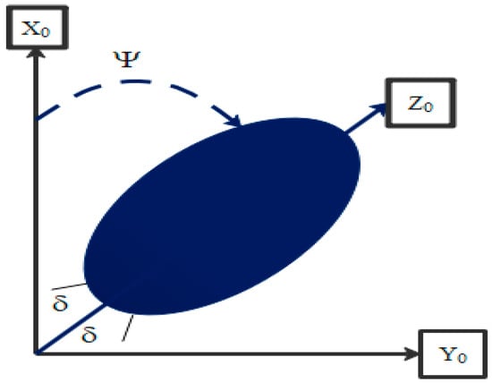
Figure 2.
Heading plane motion of the autonomous underwater vehicle.
The nonlinear equation stated in the preceding equations is used to derive the autonomous underwater vehicle’s static and dynamic coefficients. To simplify all of the equations, modify the aforementioned formulae, and assume that there are no hydrostatic forces in any of the three axes (x, y, or z). Since u = U, the axial drag is given by X u = X u/u × 2U. Heave velocity and pitch rate must both be zero for the autonomous underwater vehicle’s cross-flow drag to be linearized. All added masses and cross-flow-added mass terms should be kept when solving the following equations, but other cross terms need to be changed. Similar to this, all terms in the X, Y, and N axes are added together to calculate body lift coefficients, moments, and forces. The value of the linearized coefficients and inertia along all axes are calculated as shown in Table 2 and Table 3.

Table 2.
Value of linearized coefficient.

Table 3.
Autonomous underwater vehicle’s inertia value along various axes.
Thus, the autonomous underwater vehicle’s kinematics can be described as [1,2] and represented by Equations (23)–(25). On the other hand, Equations (26)–(28) show the autonomous underwater vehicle’s dynamics.
The total force in the x-axis is as follows:
The total force in the y-axis is as follows:
The total moments in the z-axis are as follows:
The reduced linearized form equation of motion in a heading plane model of autonomous underwater vehicles is presented in Equations (30)–(32).
Considering that Y is very small, the state space is given by Equation (32).
Applying all the parameter values from Table 2 and Table 3 in Equation (32), Equation (33) includes the state space equation for the heading plane of the autonomous underwater vehicle.
The heading plane control loop depicted in Figure 3 states that the inner control loop governs the autonomous underwater vehicle’s rudder angle, while the outer control loop governs the heading angle.
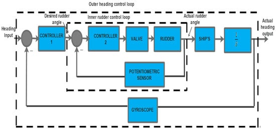
Figure 3.
Control loop of heading plane.
The control law is created in a way that forces the autonomous underwater vehicle to travel in the fixed direction that is desired and to stay there. The orientation of the rudder in the inner control loop is the control input that helps the autonomous underwater vehicle stay pointed in the right direction. However, the rudder’s ability to move is physically constrained. The autonomous underwater vehicle’s unbalance may result from high yaw rates, which can also cause roll and sway motion. As a result, the rudder angle of the autonomous underwater vehicle completely determines how the outer control loop measures the heading angle. Therefore, while navigating an autonomous underwater vehicle, restrictions must be placed on rudder orientation and yaw rate.
2.2. Depth Plane Control
The depth plane model of the autonomous underwater vehicle is shown in Figure 4. Here, body is fixed, and earth is taken as reference.
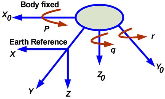
Figure 4.
Autonomous underwater vehicle’s depth plane motion.
The depth plane control of the autonomous underwater vehicle uses two control loops. The pitch angle and depth of the autonomous underwater vehicle system are controlled by the inner and outer control loops, respectively, which are described in Figure 5. The current autonomous underwater vehicle assumes the pitch angle (θ) is zero, forward speed is nearly constant, and wind wave is ignored.
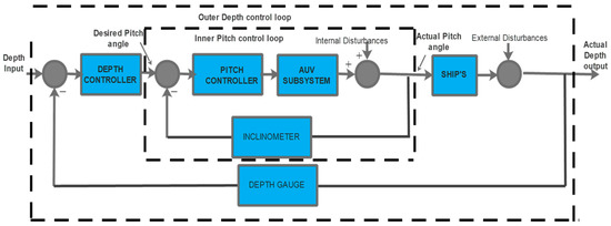
Figure 5.
Block diagram of autonomous underwater vehicle’s depth plane control.
The individual components of depth plane motion of the autonomous underwater vehicle are simplified [3] in Equation (34).
and
The standard diving equation of the depth plane motion of the autonomous underwater vehicle is simplified in Equation (35).
3. Controlling Techniques
In this section, different controlling techniques such as fuzzy logic controller, self-tuning fuzzy-PID, and ANFIS are implemented. The working principles and simulation design of these controllers are same for both heading plane and depth plane control.
3.1. Fuzzy Logic Controller
The dynamics of an autonomous underwater vehicle are uncertain, and the heading plane and depth plane trajectory control involves several uncertainties. FLC is one of the soft computing techniques used for simulating the complex systems. The interesting characteristic of the controller is the usage of linguistic variables that are closer to human thoughts. The four primary components of the controller are explained briefly, and the overall structure is shown in Figure 6.
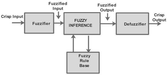
Figure 6.
Schematic for a fuzzy logic controller.
In order to successfully track the desired depth and heading for the autonomous underwater vehicle, FLC accepts the error and derivative error and generates the appropriate input. The crisp value is transformed into a fuzzy set during fuzzification. The FLC receives two control variables as input: ΔE (error) and ΔDE (derivative error). Figure 7 and Figure 8 depict the two input variables ER and DE represented as seven triangular membership functions, and Figure 9 depicts the output variable (out) as nine triangular membership function.
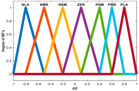
Figure 7.
Input variable MFs of error (ΔE).
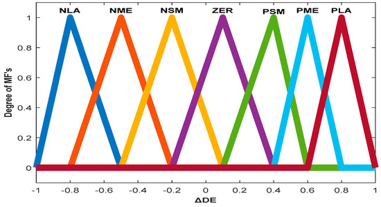
Figure 8.
Input variable MFs of change in error (ΔDE).
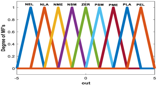
Figure 9.
Output variable MFs.
Each input variable, such as ΔE and ΔDE, has seven triangular MFs; therefore, 49 fuzzy rules are prepared for FLC, as shown in Table 4. The MFs for input variables are defined as negative large (NLA), negative medium (NME), negative small (NSM), zero (ZER), positive small (PSM), positive medium (PME), and positive large (PLA). The MFs for out variable are defined as negative extra-large (NEL), positive extra-large (PEL), negative large (NLA), negative medium (NME), negative small (NSM), zero (ZER), positive small (PSM), positive medium (PME), and positive large (PLA).

Table 4.
Fuzzy rule of error (ΔE) and change in error (ΔDE).
The fuzzy inference is based on max-min principle, where there are two fuzzy variables with triangular MFs, and follows with given rule. Mathematically, it can be represented using Equation (37).
are MFs of two input fuzzy variables, and is the fuzzy resultant composite MF of output fuzzy variables.
Defuzzification method is used to obtain crisp output from the fuzzy set. There are different kinds of defuzzification methods used to find the crisp output, such as centroid, mean of maxima, and center of sums. Output is found from the composite fuzzy set, and it is achieved by centroid method, which is followed in this paper.
The autonomous underwater vehicle follows a third-order system for the measurement of depth, which results in very slow system response. In order to make the time of response very fast, the FLC is combined with phase lag compensator, where the time-response characteristics produce satisfactory results during effective depth trajectory tracking.
3.2. Self-Tuning Fuzzy-PID
Many researchers are doing research work on hybrid intelligent algorithms, especially using the fuzzy logic concept. The self-tuning fuzzy-PID controller is designed as the fuzzy inference system tunes the PID parameters (), which depend on fuzzy rules. The self-tuning fuzzy-PID structure is given in Figure 10.
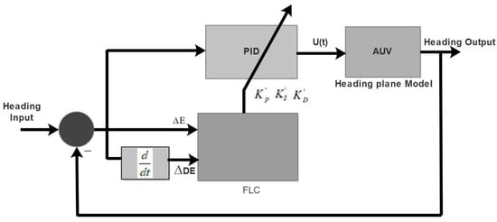
Figure 10.
Block diagram of self-tuning fuzzy-PID.
Error (ER) and change in error (DE) are the input of FLC, and outputs are PID tuning parameters such as . The tuned PID parameters are given in Equations (38)–(40).
Based on the knowledge of error and change in error, a number of rules are assigned to tune the PID parameters (). Figure 11 depicts the self-tuning fuzzy-PID’s two-input and three-output fuzzy inference system.

Figure 11.
Two-input and three-output fuzzy inference system.
After tuning PID parameters [10], the controller output is represented using Equation (41).
The triangle MFs with seven linguistic variables are considered for each input variables ER (error) and change in error (DE).
ΔE = {NEL, NME, NSM, ZER, PSM, PME, PEL}
ΔDE = {NLA, NME, NSM, ZER, PSM, PME, PLA}
Similarly, the MFs of output are also described with seven linguistic variables and are assigned as follows:
Fuzy rules are dsigned to get greater accuraccy of the autonomous underwater vehicle system and also depends on practical knowledge experience of the designer.
The designing of fuzzy rules of the self-tuning fuzzy-PID controller is as follows:
- If the deviation error is greater, the KP value should be viewed as being larger, the KD value should be smaller, and the KI value should be as small as possible;
- Where deviation error is medium (intermediate), should be small to reduce the percentage of overshoot;
- Where deviation error is small, should be larger value to improve the stability, and is mentioned.
3.3. ANFIS Controller
ANFIS is a five-layered feed-forward neural network model. The ANFIS is a unique blend of a fuzzy inference system and learning algorithm of an artificial neural network. ANFIS initiates with a prior well-constructed framework. The neural system needs a pair of information, such as input and output data, for training purpose. As it is linguistically structured, the intermediate results can be implemented through a first-order Sugeno fuzzy system, which has more computational efficiency and flexibility. ANFIS trains the paired data set of the target, and taking into consideration the best response of the system, the objective can be obtained. By its very nature, FLC has proven a bit complex in developing membership functions and yielding fuzzy rules, so in most of the cases, the rules are designed in a randomized way. To avoid the above demerits, the globally applicable control model, i.e., ANFIS, was developed. The schematics of the ANFIS structure are briefly explained in Figure 12.
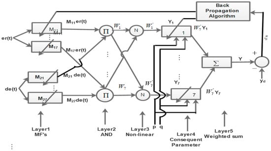
Figure 12.
Block diagram of ANFIS controller techniques.
The two inputs of ANFIS controller are er(t) and de(t).
where Zr is the reference depth, Zd is the desired depth, and T is the sampling time. There are seven Gaussian-type fuzzy rules of the proposed Sugeno fuzzy model. The output of singleton membership function is defined using Equation (42).
where m1i, m2i, and ri are the training parameters.
yi = m1ier(t) + m2i de(t) + ri
Layer1: All nodes in this layer of fuzzification are adaptable nodes. A gradient descent algorithm is used to optimize the input MFs such as error (ΔE) and derivative error (ΔDE). The output of this layer is represented using Equations (43) and (44).
Oi1 = µ1i(er(t)), i = 1, 2, ….7
Oi1 = µ1i(de(t)), i = 1, 2, ….7
µ1i and µ2i are the Gaussian-type MFs, as shown in Figure 13.
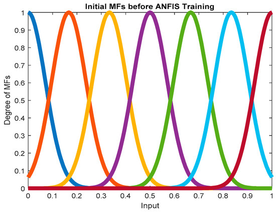
Figure 13.
Initial MFs before ANFIS training.
Layer2: This layer evaluates the rule’s firing power for the two inputs, and it is a fixed node represented by π, operated with fuzzy AND operator.
WiOi2 = µ1i(er(t))·µ2i(de(t)), i = 1, 2, ….7
Layer3: As a fixed node, this layer is denoted by the letter N. The weight is calculated in every node. There are ith number of weights with the firing strength of the rule. The normalized firing strength is calculated as .
Layer4: Each and every node in this layer is an adaptive node, and the output of this node comprises normalized firing strength () and consequent parameter (yi).
where
yi = m1ier(t) + m2ide(t) + ri, i = 1, 2, …7
Layer 5: Each and every node in this layer is a fixed node and represented by a symbol (Σ). The overall ANFIS output is calculated as the overall addition of incoming signals to this node.
ANFIS Controller Training
The proposed ANFIS controller [36,37] is designed with the back-propagation algorithm and reduces error by least square method. This algorithm has salient features such as fast convergence rate and less complexity in computation. For the weight updating, the steepest descent gradient algorithm is used. The cost function of the adaptive system is defined as follows:
where, the desired output is yd, and y is what the ANFIS model actually produces. Therefore, for the proposed ANFIS model, the cost function is redefined as follows:
where, Zd is the desired depth response, and Z is the estimated depth output of the autonomous underwater vehicle. As per the back-propagation adaptive algorithm, the updated parameters can be evaluated as follows:
where p, q are input parameters; w is the weight; and η is the fixed learning rate.
pi(k + 1) = p(k) − η ∇pE(k)
qi(k + 1) = q(k) − η ∇qE(k)
w(k + 1) = w(k) − η∇E(k)
∇E(k), ∇E(k), and ∇E(k) are the gradient of cost function E corresponding to parameters (, , ) that are described in the equation below.
The differential terms of the above equations are briefly described and mentioned below.
The value of k is considered greater than zero.
As the error propagates in a backward manner for the back-propagation algorithm, so the shape of Gaussian MFs is modified after training. The MFs before and after training are given in Figure 13 and Figure 14, respectively.
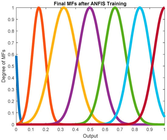
Figure 14.
Final MFs after ANFIS training.
The error curves start to decrease and follow the gradient algorithm where minimized Rmse is 0.140414 for depth control, which is shown in Figure 15. Similarly, the Rmse value of heading plane control is 0.09912, as shown in Figure 16.
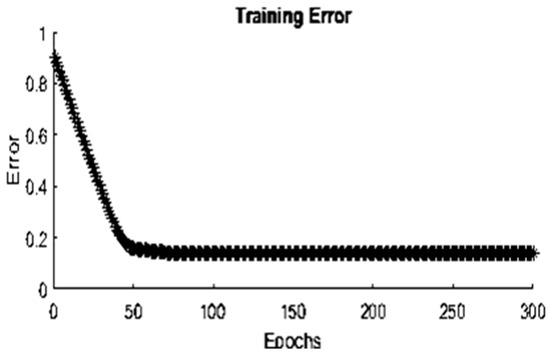
Figure 15.
Training error curve of proposed ANFIS control for depth plane.
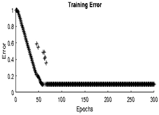
Figure 16.
Training error curve of proposed ANFIS control for heading plane.
After training the input data, the five-layer Simulink structure of the ANFIS model is obtained, and it is shown in Figure 17. To better understand the implementation process of the ANFIS model, it is briefly explained in the flow chart illustrated in Figure 18. Initially, the depth plane parameters are considered as input training data, and each input is defined with MFs. In next step, the number of epochs and percentage of training data are described for training the model. After, the successful training yields the best FIS and training results of ANFIS model, which is mentioned in third step. In the final step, compliance of the input parameter for the prediction and prediction result is attained, which is compared with evaluated result of the depth controller parameter.

Figure 17.
ANFIS Simulink structure.
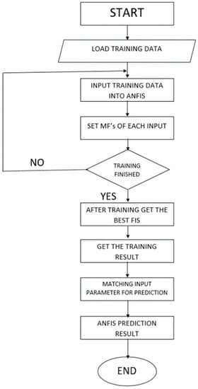
Figure 18.
Flow chart of ANFIS control technique.
4. Simulation Results
This section explains an example of how the suggested ANFIS controller techniques performed for the autonomous underwater vehicle in depth and heading planes. Using the MATLAB/Simulink tool, the behavior of the autonomous underwater vehicle’s mathematical model is simulated, and the effectiveness of the ANFIS is evaluated in comparison to traditional PID, FLC, and self-tuning fuzzy-PID controller techniques. Figure 19 and Figure 20 show, respectively, a brief explanation of the step response result analysis of the heading and depth plane controls. To start, the heading and depth planes of the autonomous underwater vehicle are controlled using the conventional PID controller gains that are obtained from online PID tuning separately. This controller provides satisfactory performance but produces large overshoot and more settling time, as shown in Table 5 and Table 6.
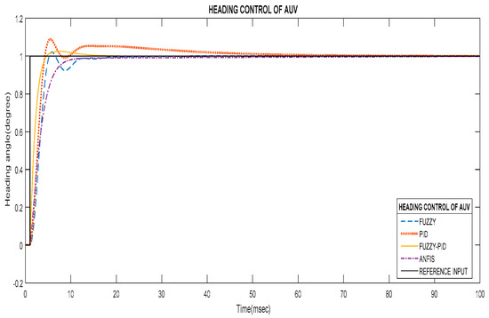
Figure 19.
Step response curve of heading plane control by FLC, PID, self-tuning fuzzy-PID, and ANFIS control techniques.
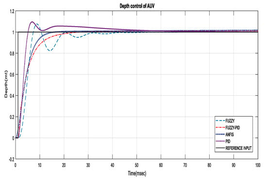
Figure 20.
Time-response curve of depth plane control by FLC, PID, fuzzy-PID, and ANFIS control techniques.

Table 5.
Time-response characteristics comparison of heading plane control.

Table 6.
Time-response characteristics comparison of depth control.
The autonomous underwater vehicle system, which is a third-order system, was compensated with a lag compensator, which significantly improved the system’s time-response performance. The Mamadani FLC was introduced to produce better timing. The disturbances were added at the input side of the system, but the controller gives it good load rejection capability, allowing it to achieve the desired response and readily stabilizing the system. The self-tuning fuzzy-PID controller is a hybrid technique, and the old (KP, KI, and KD) parameters need to be designed before simulation of the FPID model. The nonlinear equation of the controller output is able to control both autonomous underwater vehicle systems with the desired time response. The proposed ANFIS model does a better job of controlling the parameters of the nonlinear mathematical autonomous underwater vehicle model, resulting in a more accurate and faster response. Since ANFIS combines fuzzy logic and neural networks, it provides accuracy to non-linear systems such as autonomous underwater vehicles. Without exclusively relying on expert knowledge sufficient for a fuzzy logic model, the ANFIS model can be trained. The proposed model benefits from having both linguistic and numerical knowledge. The ANFIS controller outperforms the PID, FLC, and self-tuning fuzzy-PID controllers according to their responses. As a result, the proposed system offers significantly improved functionality in terms of flexibility, consistency, ability to adapt, and capacity for quick learning. The time-response characteristics in terms of rise time, settling time, and overshoot comparison of the heading and depth planes of the autonomous underwater vehicle are shown in Table 5 and Table 6, respectively. The overshoot of the proposed ANFIS controller for both control operations is almost zero in comparison to that of other controller techniques. Similarly, this controller produces better speed response with a minimum settling time.
In this paper, the tracking performance of a heading controller with multi-step, square, and ramp inputs is examined. The autonomous underwater vehicle successfully tracks the desired heading with various inputs applied to the model, as shown in Figure 21, Figure 22 and Figure 23. The performance of PID and FLC in terms of overshoot and settling time is very poor, but the performance is much better with the ANFIS. Figure 24 and Figure 25 show the time-response performance, as represented on the bar chart of the heading and depth planes, respectively.
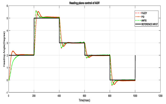
Figure 21.
Multi-step response of heading plane control.
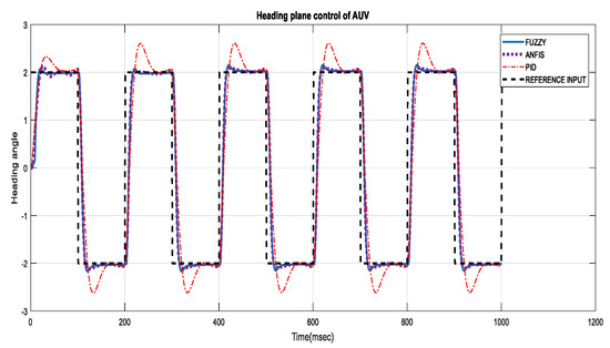
Figure 22.
Square wave response of heading plane control.
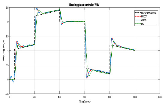
Figure 23.
Ramp response of heading plane control.
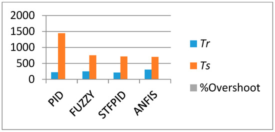
Figure 24.
Bar chart of the heading plane control.
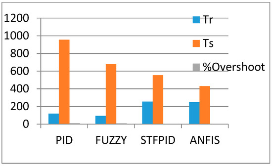
Figure 25.
Bar chart of the depth plane control.
Owing to its minimal oscillation, better speed, and accurate steady state response, the proposed ANFIS controller’s data are referred to as referential target input, and the other controllers such as ANFIS, FLC, and self-tuning fuzzy-PID are considered as input data for NN optimization. The MATLAB neural network tool is used for the optimization of controller response. Up until the network reaches the reference target, the NN is trained. The output is correctly predicted by the training network based on the target data. As a result, it can be said that the NN effectively models and predicts the autonomous underwater vehicle’s heading angle. The derivative of the loss function is taken into account when using the gradient descent algorithm in this case, and the expected value of the target can be expressed as a weighted sum of the functions. The results related to the training, validation, testing, and regression of self-tuning fuzzy-PID, ANFIS, and FLC controllers are described in Figure 26, Figure 27 and Figure 28, respectively. The regression value of the ANFIS controller is comparatively high compared to that of other controllers. The overall regression values of all controllers are represented as a clustered cone bar graph and shown in Figure 29. In comparison to FLC and self-tuning fuzzy-PID controllers, it was found that the autonomous underwater vehicle system based on the ANFIS controller significantly reduces overshoot with essentially no loss of accuracy.
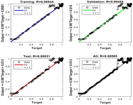
Figure 26.
Results of fuzzy after NN optimization.
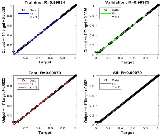
Figure 27.
Results of self-tuning fuzzy-PID after NN optimization.
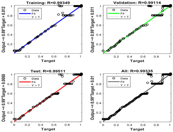
Figure 28.
Results of PID after NN optimization.
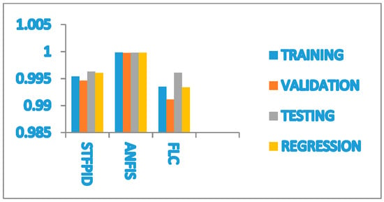
Figure 29.
Clustered cone bar graph of various controllers.
5. Conclusions
The self-tuning fuzzy logic controller has the advantages of quick response, excellent anti-interference ability, and more, according to experiments and simulations. The PID controller has the largest steady-state error, while the fuzzy-based controller has a slightly longer average rising time than the others. While the autonomous underwater vehicle is controlled for both heading and depth, the steady-state error of the STFLC gradually decreases, and the response gets closer to the desired value. The time-response performance in controlling both heading and depth significantly improved with the use of the designed ANFIS controller model, which was the subject of this study. The ANFIS’s gradient error-based self-learning mechanism is capable of handling the nonlinearities and uncertainties present in underwater motion both in terms of depth and heading plane. Accurate heading angle determination for underwater vehicles towards targets is possible by using the ANFIS approach in a variety of ways. The effectiveness of an underwater vehicle during different path movements can be demonstrated by simulation results. The proposed ANFIS controller has a quick response, less overshoot, minimal error, and better heading and depth-tracking capability than the traditional PID, FLC, and self-tuning fuzzy-PID controller models.
Author Contributions
Conceptualization, N.N.; Methodology, N.N., K.K.S. and M.A.; Software, T.K.P., H.D. and S.S.A.; Validation, T.K.P.; Formal analysis, S.R.D. and T.K.P.; Investigation, S.R.N.; Resources, S.R.N.; Data curation, H.D.; Writing—original draft, N.N., M.A.; Writing—review & editing, S.R.D. and K.K.S.; Funding acquisition, S.S.A. All authors have read and agreed to the published version of the manuscript.
Funding
This project is funded by King Saud University, Riyadh, Saudi Arabia. Researchers Supporting Project number (RSP2023R167), King Saud University, Riyadh, Saudi Arabia.
Data Availability Statement
Data will be made available on request.
Acknowledgments
Researchers Supporting Project number (RSP2023R167), King Saud University, Riyadh, Saudi Arabia.
Conflicts of Interest
The authors declare that they have no competing interest.
References
- Fossen, T.I. Guidance and Control of Ocean Vehicles; Wiley: Hoboken, NY, USA, 1994. [Google Scholar]
- Fossen, T.I. Maritime Control Systems—Guidance, Navigation and Control of Ships, Rigs and Underwater Vehicles. In Marine Cybernetics; Springer: Trondheim, Norway, 2002. [Google Scholar]
- Fossen, T.I. Handbook of Marine Craft Hydrodynamics and Motion Control; Norwegian University of Science and Technology: Trondheim, Norway, 2011. [Google Scholar]
- Huang, H.; Zhang, C.; Ding, W.; Zhu, X.; Sun, G.; Wang, H. Design of the Depth Controller for a Floating Ocean Seismograph. J. Mar. Sci. Eng. 2020, 8, 166. [Google Scholar] [CrossRef]
- Tchilian, R.S.; Rafikova, E.; Gafurov, S.A.; Rafikov, M. Optimal control of an underwater glider vehicle. Procedia Eng. 2017, 176, 732–740. [Google Scholar] [CrossRef]
- Srivastava, A.; Tripathy, A.K.; Prasad, M.P.R. Comparative Analysis on Depth Control of an Underwater Vehicle. In Proceedings of the Innovations in Power and Advanced Computing Technologies, Vellore, India, 22–23 March 2019; pp. 1–5. [Google Scholar]
- Liu, C.; Yue, X.; Shi, K.; Sun, Z. Spacecraft Attitude Control: A Linear Matrix Inequality Approach; Elsevier: Amsterdam, The Netherlands, 2022. [Google Scholar]
- Liu, C.; Shi, K.; Yue, X.; Sun, Z. Inertia-free saturated output feedback attitude stabilization for uncertain spacecraft. Int. J. Robust Nonlinear Control 2020, 30, 5101–5121. [Google Scholar] [CrossRef]
- Zhao, T.; Chen, Y.; Dian, S.; Guo, R.; Li, S. General type-2 fuzzy gain scheduling PID controller with application to powerline inspection robots. Int. J. Fuzzy Syst. 2020, 22, 181–200. [Google Scholar] [CrossRef]
- Huo, X.; Ge, T.; Wang, X. Horizontal path-following control for deep-sea work-class ROVs based on a fuzzy logic system. Ships Offshore Struct. 2018, 13, 637–648. [Google Scholar] [CrossRef]
- Xiang, X.; Yu, C.; Lapierre, L.; Zhang, J.; Zhang, Q. Survey on Fuzzy-Logic-Based Guidance and Control of Marine Surface Vehicles and Underwater Vehicles. Int. J. Fuzzy Syst. 2018, 20, 572–586. [Google Scholar] [CrossRef]
- Zadeh, L.A. Fuzzy sets. Inf. Control 1965, 8, 338–353. [Google Scholar] [CrossRef]
- Chu, Z.; Xiang, X.; Zhu, D.; Luo, C.; Xie, D. Adaptive Fuzzy Sliding Mode Diving Control for Autonomous Underwater Vehicle with Input Constraint. Int. J. Fuzzy Syst. 2018, 20, 1460–1469. [Google Scholar] [CrossRef]
- Londhe, P.S.; Patre, B.M. Adaptive fuzzy sliding mode control for robust trajectory tracking control of an autonomous underwater vehicle. Intell. Serv. Robot. 2019, 12, 87–102. [Google Scholar] [CrossRef]
- Londhe, P.S.; Dhadekar, D.D.; Patre, B.M.; Waghmare, L.M. Uncertainty and disturbance estimator based sliding mode control of an autonomous underwater vehicle. Int. J. Dyn. Control 2017, 5, 1122–1138. [Google Scholar] [CrossRef]
- Yao, F.; Yang, C.; Liu, X.; Zhang, M. Experimental Evaluation on Depth Control Using Improved Model Predictive Control for Autonomous Underwater Vehicle (AUVs). Sensors 2018, 18, 2321. [Google Scholar] [CrossRef] [PubMed]
- Sudirman, R.M.; Effend, R. Model Predictive Control of Autonomous Underwater Vehicles Based on Horizon Optimization. JAREE-J. Adv. Res. Electr. Eng. 2020, 4, 107884. [Google Scholar] [CrossRef]
- Makavita, C.D.; Jayasinghe, S.G.; Nguyen, H.D.; Ranmuthugala, D. Experimental Study of Command Governor Adaptive Control for Unmanned Underwater Vehicles. IEEE Trans. Control Syst. Technol. 2019, 27, 332–345. [Google Scholar] [CrossRef]
- Chen, Y.; Wang, K.; Chen, W. Adaptive fuzzy depth control with trajectory feedforward compensator for autonomous underwater vehicles. Adv. Mech. Eng. 2019, 11, 1687814019838172. [Google Scholar] [CrossRef]
- Guerreroa, J.; Torresa, J.; Creuzeb, V.; Chemorib, A. Trajectory tracking for autonomous underwater vehicle: An adaptive approach. Ocean Eng. 2019, 172, 511–522. [Google Scholar] [CrossRef]
- Wang, N.; Sun, J.C.; Er, M.J. Tracking-error-based universal adaptive fuzzy control for output tracking of nonlinear systems with completely unknown dynamics. IEEE Trans. Fuzzy Syst. 2018, 26, 869–883. [Google Scholar] [CrossRef]
- Zheng, Z.; Huang, Y.; Xie, L.; Zhu, B. Adaptive trajectory tracking control of a fully actuated surface vessel with asymmetrically constrained input and output. IEEE Trans. Control Syst. Technol. 2017, 97, 83–91. [Google Scholar] [CrossRef]
- Makavita, C.D.; Jayasinghe, S.G.; Nguyen, H.D.; Ranmuthugala, D. Experimental Study of a Command Governor Adaptive Depth Controller for an Unmanned Underwater Vehicle. Appl. Ocean Res. 2019, 86, 61–72. [Google Scholar] [CrossRef]
- Manzanilla, A.; Castillo, P.; Lozano, R. Nonlinear algorithm with adaptive properties to stabilize an underwater vehicle real-time experiments. IFAC 2017, 50, 6857–6862. [Google Scholar] [CrossRef]
- Wang, N.; Qian, C.; Sun, J.C.; Liu, Y.C. Adaptive robust finite time trajectory tracking control of fully actuated marine surface vehicles. IEEE Trans. Control Syst. Technol. 2016, 24, 1454–1462. [Google Scholar] [CrossRef]
- Hassaneina, O.; Anavattib, S.G.; Shimc, H.; Ray, T. Model-based adaptive control system for autonomous underwater vehicles. Ocean Eng. 2016, 127, 58–69. [Google Scholar] [CrossRef]
- Cui, R.; Yang, C.; Li, Y.; Sharma, S. Adaptive Neural Network Control of AUVs With Control Input Nonlinearities Using Reinforcement Learning. IEEE Trans. Syst. Man Cybern. Syst. 2017, 47, 1019–1029. [Google Scholar] [CrossRef]
- Geranmehr, B.; Vafaee, K. Hybrid Adaptive Neural Network AUV Controller Design with Sliding Mode Robust Term. IJMT 2017, 72, 49–55. [Google Scholar] [CrossRef]
- Alvarado, R.H.; Valdovinos, L.G.G.; Jiménez, T.S.; Espinosa, A.G.; Navarro, F.F. Neural Network-Based Self-Tuning PID Control for Underwater Vehicles. Sensors 2016, 16, 1429. [Google Scholar] [CrossRef]
- Huang, H.; Zhang, G.; Qing, H.; Zhou, Z. Autonomous underwater vehicle precise motion control for target following with model uncertainty. Int. J. Adv. Robot. Syst. 2017, 14, 1729881417719808. [Google Scholar]
- Xiang, X.; Yu, C.; Zhang, Q. Robust fuzzy 3D path following for autonomous underwater vehicle subject to uncertainties. Comput. Oper. Res. 2017, 84, 165–177. [Google Scholar] [CrossRef]
- Jin, P.; Wang, B.; Li, L.; Chao, P.; Xie, F. Semi-supervised underwater acoustic source localization based on residual convolutional auto encoder. EURASIP J. Adv. Signal Process. 2022, 2022, 107. [Google Scholar] [CrossRef]
- Ma, H.; Mu, X.; He, B. Adaptive Navigation Algorithm with Deep Learning for Autonomous Underwater Vehicle. Sensors 2021, 21, 6406. [Google Scholar] [CrossRef]
- Wu, H.; Song, S.; You, K.; Wu, C. Depth control of model-free AUVs via reinforcement learning. IEEE Trans. Syst. Man Cybern. Syst. 2018, 49, 2499–2510. [Google Scholar] [CrossRef]
- Duan, K.; Fong, S.; Chen, C.P. 2022. Reinforcement learning based model-free optimized trajectory tracking strategy design for an AUV. Neurocomputing 2022, 469, 289–297. [Google Scholar] [CrossRef]
- Parhi, D.R.; Kundu, S. Reactive Navigation of Underwater Mobile Robot Using ANFIS Approach in a Manifold Manner. Int. J. Autom. Comput. 2017, 14, 307–320. [Google Scholar]
- Nayak, N.; Das, P.; Das, S.R. Heading plane control of an autonomous underwater vehicle: A novel fuzzy and model reference adaptive control approach. In Proceedings of the 2020 Third International Conference on Advances in Electronics, Computers and Communications (ICAECC), Bengaluru, India, 11–12 December 2020; pp. 1–5. [Google Scholar]
Disclaimer/Publisher’s Note: The statements, opinions and data contained in all publications are solely those of the individual author(s) and contributor(s) and not of MDPI and/or the editor(s). MDPI and/or the editor(s) disclaim responsibility for any injury to people or property resulting from any ideas, methods, instructions or products referred to in the content. |
© 2023 by the authors. Licensee MDPI, Basel, Switzerland. This article is an open access article distributed under the terms and conditions of the Creative Commons Attribution (CC BY) license (https://creativecommons.org/licenses/by/4.0/).