Abstract
Coordinated operation of hydrothermal scheduling with HVDC links considering network constraints becomes a vital issue due to their remote location and recent induction in the existing power system. The nonlinear and complex nature of the problem introduces many variables and constraints which results in a heavy computational burden. A widespread approach for handling these complexities is to reformulate the problem by several linearization methods. In this paper, a Lagrange multipliers-based method is proposed for the solution of hydrothermal economic scheduling including HVDC link. This method solves equality constraint optimization problems. The linear programming approach is embedded with the Lagrange method to consider both equality and inequality constraints. The proposed technique has been used on piecewise linear variables and constraints of the system considering generation, water volume, and line power flow limits. The formulated method efficiently minimizes the operational cost of thermal units and maximizes the utilization of hydro units while meeting all generation, water volume, and the HVDC link constraints. The method was successfully implemented in two scenarios of a case study. In the first scenario, hydrothermal scheduling was performed on the typical network without an HVDC line limit and equal nodal prices were found with minimal thermal generation cost of $278,822.3. In the second scenario, the proposed method optimally dispatches units to meet the HVDC line limit and minimizes thermal generation cost to $279,025.4 while satisfying hydro, thermal, and other operating constraints. Both scenarios are implemented for a 24 h period. The results have been presented to illustrate the performance of the proposed method.
Keywords:
linear programming; economic dispatch; hydrothermal scheduling; HVDC link; Lagrange multipliers; optimal power flow MSC:
49-11
1. Introduction
Recently, an increase in energy demand and fossil fuel prices has raised the cost of energy generated by thermal power plants. The world has reduced the use of costly and inefficient thermal plants by inducting renewable energy resources and hydel power generation [1,2]. The energy prices can also be minimized by optimal scheduling of resources [3,4]. Conventionally, power is transmitted to loads through AC transmission lines. However for long distance, the HVDC link becomes more efficient and cost effective as compared to the conventional mode of transmission [5]. Therefore, the coordinated economical operation of hydrothermal units with HVDC links has emerged as an interesting research area in today’s world of increasing energy stress.
Different researchers have discussed different aspects of hydrothermal scheduling considering HVDC systems. Hydrothermal scheduling is a complex and non-linear constrained optimization problem. Inclusion of HVDC links increases the complexity of the problem that can be addressed by good computational tools. Hydrothermal scheduling problems were successfully solved using conventional methods such as Lagrange multipliers method (LMM) [6], Newton–Raphson method [7,8], gradient search algorithm [9], mixed integer programming [10], and dynamic programming [11]. A number of heuristic and metaheuristic algorithms are used to solve hydrothermal scheduling problems [12,13,14]. A few recently used algorithms in hydrothermal scheduling operation are rigid cuckoo search algorithm [15], firefly and accelerated particle swarm optimization [16], Lagrangian relaxation [13], grasshopper optimization algorithm (GOA) [17], and artificial bee colony algorithm [18]. However, heuristic algorithms cannot deal effectively with premature convergence problems. Additionally, when dealing with the large number of variables in optimization, the computation time of heuristic algorithms increases drastically. Each metaheuristic technique has some weaknesses and strengths to find near the optimal solutions for hydrothermal scheduling [19]. Meanwhile, mathematical programming methods are computationally fast and provide stable solution each time [20]. In unit commitment and economic dispatch cases, the linear programming (LP) method gives better results than the genetic algorithm (GA) technique [21]. The literature shows that hydrothermal scheduling has been effectively performed by the Lagrange multipliers method [6,22].
The induction of HVDC links in the existing power system requires an optimal power flow (OPF) study for realistic hydrothermal scheduling. Formulation and implementation of HVDC systems for OPF has been performed in reference [23]. Combined economic operation of point-to-point VSC-HVDC and AC grids is also performed based on Lagrange multipliers efficiently [24]. Joint operation of two area HVDC links has been performed in reference [20] to improve the operational economy and efficiency. Optimal scheduling of fixed head hydrothermal scheduling considering wind uncertainty is conducted in [25]. The literature survey signifies that hydrothermal scheduling was performed using various optimization techniques under various operating conditions to minimize the fuel price of thermal units.
A careful review of the above-mentioned excellent research shows that the existing methods of the economical scheduling of hydrothermal power plants only consider the price minimization of thermal units subject to meeting the load, losses, and water discharge constraints. These calculations ignore the network details and result in snubbing effects of transmission branch loading and bus voltages [9]. Therefore, economical hydrothermal dispatching does have an important effect on line flows, and under HVDC line constraints, these effects need to be taken into account.
The main contributions of this research are:
- Formulation of complex hydrothermal scheduling problem.
- Modelling of AC grids to add network constraints using DC optimal power flow (DCOPF) in the existing scheduling problem.
- Induction of HVDC link with line flows limitation constraints in hydrothermal problem.
- Linearization of quadratic cost curves of thermal generators to deal with inequality constraints.
- Implementation of linear programming-based Lagrange multipliers methods on a case study to check the robustness of the proposed method.
In this paper, a novel hydrothermal scheduling problem with an HVDC link is formulated to meet the load demand and network constraints. The formulation is general and allows to find out the economic impact of HVDC link power usage on hydrothermal-based AC system. An algorithm is developed to solve such a diverse problem using linear programming-based Lagrange multipliers method as it is fast and less prone to convergence issues and more deterministic in nature as compared to existing popular metaheuristic algorithms. To the best knowledge of the authors, such a coordinated economic operation of hydrothermal units with HVDC links keeping in view the power network constraints has not been discussed before.
The rest of the paper is arranged as follows. Section 2 presents the detailed formulation of the concerned problem and proposes the solution methodology. Section 3 explains the proposed research methodology for a case study of a power system. Section 4 demonstrates the results of the case study under two different scenarios to validate the effectiveness of the proposed methodology. Section 5 concludes the discussion and presents some points for future work.
2. Problem Formulation
The coordinated economic operation of hydrothermal units with HVDC link aims to minimize the operating cost of thermal units while maximizing the utilization of available reservoir water volume, fulfilling the HVDC line flow limits and satisfying the load power balance. Figure 1 shows the generalized network diagram considered for this scenario.
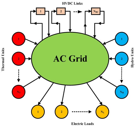
Figure 1.
Generalized network diagram.
Figure 1 shows an electric network in which a number of hydel and thermal power plants are embedded. The inward arrows show that the power is delivered to the network. The loads are attached to the network. Here, outward arrows show the flow of power from the network to the loads. The HVDC blocks take power from certain buses (represented by outward arrows) and deliver it to other buses of the network (represented by inward arrows). The idea is to propose a Lagrange function for such a network considering all the generation, load, and network constraints. The following steps are being followed.
2.1. Hydrothermal Problem Formulation
The objective of hydrothermal is to utilize a given volume of water such that to minimize the production cost of generating units subject to constraints of transmission lines, generators, and HVDC line limits. Therefore, the problem is formulated in general as subject to constraints p(x) = 0 and q(x) ≤ 0, where p(x) and q(x) are equality and inequality constraints, respectively. Equation p(x) represents the network DC optimal power flow (DCOPF)-based load power balances, while Equation q(x) denotes water volume discharge and minimum and maximum limits of hydro and thermal power generators. The cost of thermal generating units is approximated as a quadratic cost rate given in (1). Similarly, the water flow from hydro power plants in j time intervals is approximated using (2). The expressions (1) and (2) are used for the incremental cost of thermal power and fictitious cost of water, respectively, that must be paid to satisfy power balance, water volume, HVDC line limit, and generation constraints.
2.2. HVDC Line Flow Problem Formulation
A point-to-point connected HVDC system consists of two converter stations, namely rectifier and inverter stations, as shown in Figure 2. Both converter stations are connected to AC systems on ‘r’ and ‘i’ nodes through filters and tap-changing transformers. Inverter station maintains DC bus voltage within limits and rectifier station controls the active power flow at specified value [24]. The power transfer in the system can be in either direction. In the previous research, the investigations have been carried out to optimize the controller gains to control the active power transfer in HVDC system [26]. HVDC problem formulation consists of the following steps.

Figure 2.
HVDC system.
Modelling of the point-to-point HVDC grids has been extensively performed to couple the VSC station with an AC network as an ideal voltage source either through an impedance or by phase shifting transformer for power flow analysis [27,28,29,30,31]. Similarly, intensive literature exists in the domain of economic dispatch for renewables ([32,33,34,35,36] and references therein). It is vital for economic dispatch applications to formulate the power flow equations of HVDC link from inverter to rectifier and vice versa. The DC power flow expression from inverter and rectifier, respectively, are given in (3).
where and are inverter and rectifier voltages, respectively, and .
To formulate the combined equations for HVDC power flow and AC grids, some basic assumptions are made on AC grid: (a) neglect conduction losses, i.e., , (b) set , and (c) due to very small angular difference, set . Hence, (6) takes the form for nodal power balances in various nodes of HVDC grid and defines the equality constraints for HVDC link. The resultant expression becomes as given in (4):
where , , represent susceptance and phase angle on rectifier and inverter side, respectively. Susceptance is the inverse of reactance offered by AC filter, reactors, and transformer on either side of the converter.
2.3. AC Network Problem Formulation
The nodal power balance is formulated based on the operating point of the AC system. The power balance relation in (5) exhibits equality constraints p(x) as a function of nodal power generation, demand, and calculated power in (6).
where and are the voltage magnitudes and phase angles of the transmission lines linking buses ‘k’ and ‘m’, respectively. Moreover, G and B are conductance and susceptance of lines connecting the respective busses, respectively.
Under steady state condition of AC grid, and with negligible power loss , the expression (6) reduces to . Then, this expression can be generalized for lossless AC grids having nodes in (7).
where P is nodal power, B is susceptance, and is the nodal phase angle.
The mostly used HVDC links occur either in embedded or decoupled form with the AC grids [24]. These models are used for the investigation of optimal power flow in HVDC links connected to AC systems. The embedded HVDC link model deduces that both sending and receiving end converter stations consider same phase angles to AC grid. The expressions (4) and (7) provide the relationship between two AC grids connected HVDC link for sending and receiving end power flow. The mathematical expressions (1), (2), (4), and (7) are added in the Lagrange function to augment DCOPF-based AC grid details and HVDC flow limit in hydrothermal scheduling. The resultant expression is given in (8).
2.4. Overall Problem Formulation
The objective of the research is to minimize the thermal generation cost subject to meet the load balance, generator limit, HVDC line flow, and water consumption constraints. Based on the objective and constraints, the Lagrange function is stated as given in (8);
where is the scheduling interval in hours, is the number of buses, is the thermal cost function which needs to be minimized subjected to power balance constraint and water storage constraint , is Lagrange multiplier which shows nodal marginal price of bus number in time interval in , is the load in each time interval, is the sum of power generated by thermal and hydro units in each time interval, is the actual power flow on HVDC link from rectifier to inverter, is the line flow limit of the HVDC link, and are minimum and maximum limits of thermal generators, and are minimum and maximum limits of hydro generators, is Lagrange multiplier which shows fictious cost of water, H is number of hydro units, and is the total water volume available for hydro power generation.
2.5. Constraints
The constraints of hydro and thermal power plants along with load balance and transmission limits are explained.
- Load balance constraints
- Thermal plant generation limit
- Hydro plant generation limit
- Water volume limit
- HVDC line limitation
This means power flow of lines is calculated by DC load flow to check the capacity limitations of HVDC link. In real scheduling, HVDC line limitations are obeyed as specified electric quantity trade limitations lines between regional distributors of electricity.
The proposed approach is a novel alternative to address fundamental problems, as it is structured to augment DC power flow in hydrothermal scheduling. Moreover, it is general to harmonize the number of HVDC links.
As already discussed, the quadratic cost expression, given in (1) of thermal power plants, does not include the power system network details, transmission line parameters, transmission line congestion constraints, HVDC links, etc. [37,38]. The expressions (1) and (2) only consider equality constraints of load balance and water volume. While considering the network constraints without line limits in an economic dispatch, the gradient method is used to solve the Lagrange equation [9]. Moreover, the Lagrange function considering all network constraints, hydrothermal, HVDC links, the generator’s extreme limits, and line limitations can be optimized by linear programming (LP). Hence, linear programming (LP) technique is used to solve combined hydrothermal scheduling with DCOPF considering generators’ inequality and HVDC line limit constraints. As per LP, the quadratic cost expression of thermal power plants does not satisfy the requirements. Therefore, a piecewise linear approximation of the cost function given in (1) is performed. The segment wise slopes of piecewise linear approximation are developed using (14).
In (14), the number of slope segments depends on the minimum and maximum limits of thermal power generators and step size defined by the user.
Previously, (7) gave important information about the nodal power injection considering the network admittances without real part and help in finding the angles. However, (7) does not provide the line power flows. Therefore, the proposed approach considers the line flows, network constraints, generation limits, etc., formally in (15).
where is the number of slope segments, is the number of thermal generators, P is the nodal power injections at all nodes, θ is nodal angle, is line flow for AC and HVDC system, D and E are node-arc matrices, and and are line flow limits. The is the total water volume available for generation, is the number of hydro units, and is the water discharge rate to generate hydro power in an interval. Moreover, (15) is similar to (8) with constraints mentioned as Lagrange multipliers.
3. Research Methodology
The proposed linear programming based on Lagrange multipliers research methodology shown in Figure 3 has been successfully implemented on a case study power system network shown in Figure 4 by carrying out the following steps.
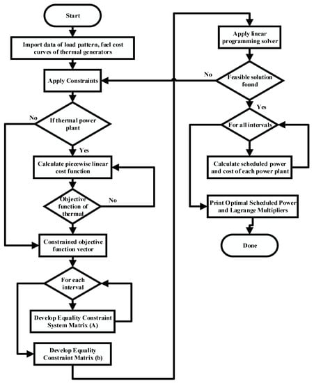
Figure 3.
Algorithm flow chart.
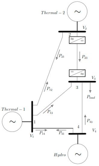
Figure 4.
Four (4) bus AC system with HVDC link.
3.1. Objective Function
The objective function is given in (16);
In (16), the dimensions of ‘’ and ‘’ (in the row) depend on the number of slopes based on step size, while and depend on the limits of the thermal power station.
3.2. Output Vector
The output vector ‘x’ for the given case study network and constraints is defined in (17).
where is the incremental generation vector for two thermal generators connected to bus-1 and bus-2, is hydropower generation, is the line power flows vector for five branches, is the vector of angles for all four buses in radian, and is the water volume variable. All these variables are added as equality constraints given in (15) to a single matrix relation. For single matrix relation, one kind of equality constraint is given as injected powers and another kind of equality constraint is given as line power flows as in (15), resulting in (18) and (19).
3.3. Equality Constraints
The equality constraints are given in (18) and (19). Matrix (Ax = b) form of equality constraints requires dimensions. The dimensions of equality constraints based on the case study are:
- Number of columns: As the vector x has 13 × 1, matrix A should have 13 columns to multiply x.
- Number of rows: As there are five branches, four buses, and one water volume constraint, (18) and (19) will have to contribute a total of ten (10) rows to matrix A.
Therefore, the dimension of matrix A will be 10 × 13. Let us start from line power flow as in (18). The D-matrix is given in (20). The node-arc matrix E, is given as (21):
The product D × E required to find line power flows is given as (22):
The elements of (22) will be placed in the upper right corner of matrix A from columns 9 to 12. The first eight columns of the top five rows will be multiplied to generated powers () and line power flows () variables. As generation variables are not used within the line power flow equations, the first three (3) columns of the top five rows will be zeros. The columns (4–8) will be zeros, except a single element in each row will be −1 to obtain corresponding line power flows.
DC power flow equations corresponding to (19) are written in matrix A. The augmented DC power flow matrix is given as (23):
Elements of (23) will be placed at the lower right of matrix A from rows 6 to 9 and columns 9 to 12. The first three (3) columns of matrix A are reserved for generation variables. The expression (19) requires negative injections for all buses and injected power is . However, load variables are not added in matrix A, which will be placed on the right side of the expression Ax = b in matrix b. Additionally, generated power from generation plants will be placed with a negative sign in the rows starting from 6 to 9 and the first three (3) columns with respect to the respective bus in matrix A. Hydro power plant and water volume constraints are added to the last (10th) row and column 3rd and 13th of the matrix A, respectively. The resultant expression Ax = b in matrix form is given in (24):
3.4. Inequality Constraints
These constraints are simple and are given in (25):
In (25), the dimensions of and depend on the number of slope segments based on and values of the thermal power generating stations. Hence, the row-wise size of columns 1 and 2 will depend on the number of slope segments. The expressions (24) and (25) are applicable to single load interval. For 24 h or daily load intervals, these equations are modified as in (26):
where and matrices have dimensions , having ten rows and thirteen columns for each load interval; is the number of load intervals h. The elements of matrix A are shown in (24) for a single load interval. The elements of matrix C are given as in (27):
Equation (27) is only used as leftover water volume in one interval to be used in the next load interval in constraint expression (24). Inequality constraints for a single load period given in (25) are modified for 24 h load intervals accordingly. The algorithm flow chart of the proposed approach is shown in Figure 3 to implement (8) using (15) with constraints from (9) to (13) and realistic equations from (16) to (27) for all load periods in MATLAB Software.
The detailed step-by-step implementation procedure of the proposed approach in MATLAB Software is given in Table 1.

Table 1.
Step-by-step implementation of proposed procedure.
4. Results and Discussion
A case study is designed to verify the effectiveness of the proposed methodology. Four bus AC systems with two AC grids are interconnected by point-to-point HVDC transmission link, shown in Figure 4. It is ensured that the modelled HVDC link agrees with (4). The cost curves of the thermal power plant and flow rate characteristics of the hydro power plant are shown in Table 2 and Table 3, respectively.

Table 2.
Thermal plants characteristics.

Table 3.
Hydro plant characteristics.
The power system network has five transmission lines connected to four different buses. The transmission line connected between bus-2 and bus-3 is considered an HVDC link. This line has point-to-point converter stations connected to the respective buses. It is assumed that all the AC lines have equal admittance with the assumption of zero real parts. Thermal unit-1 connected to bus-1 can generate a minimum power of 25 MW and a maximum power of 875 MW. However, thermal unit-2 connected to bus-2 can produce a minimum of 40 MW and a maximum of 600 MW. The hydro plant connected to bus-4 can produce a maximum of 500 MW output. The initial volume of water is 15,000 Acre-feet (AF). The allowed inflow is 1250 AF per hour. For the 24 h period, the total water available for power generation is 30,000 AF. The required ending capacity of the reservoir is 15,000 AF.
Two scenarios are implemented in Figure 4 network: (i) DCOPF including hydrothermal scheduling without line trading limitation on the HVDC line and (ii) DCOPF including hydrothermal scheduling with line trading limitation on the HVDC line. Only HVDC line has direction power flow constrain, whereas all the other lines have flexibility in the flow of power on either side.
The load is connected to bus-3 and the daily load on the four-bus system is shown in Figure 5.
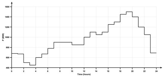
Figure 5.
Load pattern on network.
Figure 6 shows the power contribution (bar charts) of each generating station to meet the load demand. The power shared by the hydro unit to load is based on the availability of water for power generation. The power shared by both thermal units to load demand is optimized based on their cost rate characteristics shown in Table 2. Therefore, the cost of thermal power units is the minimum for typical load demand in a specific time period.
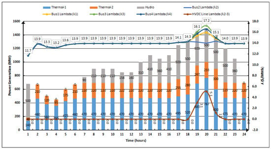
Figure 6.
Hydrothermal scheduled power, bus price, and line limit price.
Due to combined investigations of economic hydrothermal scheduling and DCOPF at the same time, the system lambdas (λ) represent the bus location marginal price (LMP) or nodal price and line congestion price instead of the generator’s incremental cost. Figure 6 shows both lambdas (λ) under two different scenarios.
4.1. Scenario-1: Infinite HVDC Line Capacity
When the power system network shown in Figure 4 is operating under normal conditions, there is no capacity limit on the HVDC transmission line. Then, the lambda (λ) of each bus is constant for a specific load period, as shown in Figure 6. In this figure, for the first load interval, the load demand is 680 MW, and the nodal price is fixed (11.7 $/MWh) for each bus. In the first interval, the hydro plant contribution is maximum. During the second load interval, load demand is 670 MW, and the nodal price is fixed (13.9 $/MWh) for each bus with zero power contribution by the hydro plant. Similarly, for load periods 1 to 18th and 22nd to 24th, nodal prices of all buses are fixed when there is an infinite line capacity limit. The resultant HVDC line limit lambda (λ2-3) is zero for these load intervals due to the infinite line capacity limit; the network considered it as a single bus. The respective power flow in each line branch and each interval is shown in Figure 7. The optimal power generation of each generating station to meet the load demand in each interval is shown in Figure 8.
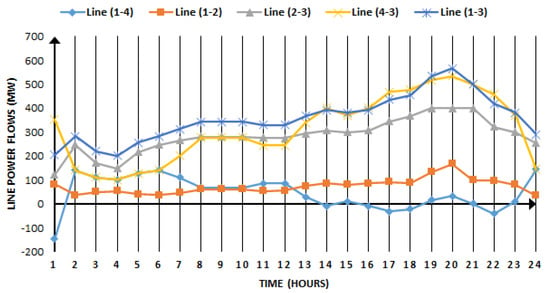
Figure 7.
Line power flow during each load interval.
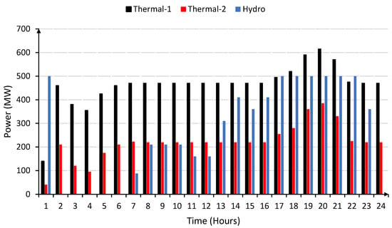
Figure 8.
Generators optimal power during each load interval in infinite line capacity.
4.2. Scenario-2: Limited HVDC Line Capacity
In this case, line trading limitation PLine2–3 = PHVDC = 400 MW is added on the HVDC link shown in Figure 4. The load power demand during time intervals 19, 20, and 21 is 1450 MW, 1500 MW, and 1400 MW, respectively, as shown in Figure 5. During these time intervals, the power shared by a hydro unit is 500 MW, thermal-1 is 683 MW, 767 MW, and 600 MW, and thermal-1 is 267 MW, 233 MW, and 300 MW, as given in Figure 6. Due to HVDC line limitations, the power is diverted to other transmission lines of the network. Hence, the network does not consider a single bus which results in different buses’ nodal lambdas (λ) price and line (λ) price. This makes the nodal price at bus-1 = λ1 = 15.4 $/MWh, bus-2 = λ2 = 14.2 $/MWh, bus-3 = λ3 = 16.1 $/MWh, and bus-4 = λ4 = 15.7 $/MWh, as shown in Figure 7. The line limit price in three different time intervals increased from 0 $/MWh to 3.1 $/MWh and 5.1 $/MWh due to line congestion heating and losses. The line limit price is shown in Figure 7. Moreover, the optimal power generation of each generating station to meet the load demand in each interval with limited line capacity is shown in Figure 9.
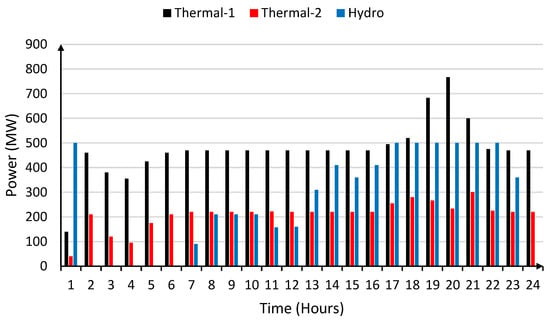
Figure 9.
Generators optimal power during each load interval in limited line capacity.
The results described in both scenarios depict that all the buses’ nodal prices are the same for specific time interval loads when there are no line limitations. Additionally, the line price is zero. Meanwhile, when there are line capacity limitations, the bus nodal price increases from 14.3 $/MWh to 17.2 $/MWh and the line price increases from 0 $/MWh to 5.1 $/MWh. This results in total cost of power generation by the thermal-1 unit in 24 h period being $170,921.4 and the thermal-2 unit being $108,104 with PHVDC = 400 MW limit. However, thermal-1 unit in 24 h period costs $166,739.8 and the thermal-2 unit costs $112,082.5 without HVDC line limitation. The proposed approach optimally scheduled the outputs of thermal generating stations under both scenarios to minimize the operating cost. It can be concluded that limited capacity HVDC links may change the optimal operating points of all generating stations throughout the load intervals. Hence, the electricity market will affect generation companies (GENCOs) and transmission system operators (TSO). Therefore, the proposed approach will be helpful in complex hydrothermal scheduling including embedded HVDC lines in existing AC networks for GENCOs and TSO to find their power generation price, bus nodal price, and line limit price.
The effectiveness of the proposed approach has been compared using interior-point and dual-simplex method. The results are presented in Table 4.

Table 4.
Comparison of different techniques.
The interior-point method solves formulated problems in 10 iterations while dual-simplex uses 292 iterations without changing any other results. However, the proposed method takes only six iterations to solve the problem.
5. Conclusions
This research article has investigated the optimal operating point of hydrothermal power plants on AC networks with the limited capacity of an HVDC line under the different operating constraints. Modelling of AC power system including VSC-HVDC link has been described for hydrothermal scheduling. The method is computationally efficient as it considers linear model of AC network with HVDC transmission link including DCOPF. Nodal bus power injection matrix is modified to embed line flow constraint in DCOPF. The quadratic cost curves of thermal generators are linearized segment wise to include the minimum and maximum generation limits. The hydro power plant is operated at maximum power (Ph = 500 MW) to obtain maximum efficiency. HVDC transmission line flow was successfully limited at PHVDC = 400 MW. The Lagrange multipliers method is used for optimal operation of hydrothermal plants on power networks. The proposed formulation is applied to two scenarios of a case study. In the first scenario of the case study, the total thermal generation cost comes out to $278,822.3. In the second scenario of the case study, the total cost of thermal generation is $279,025.4. The difference in cost in both scenarios is minimum. It is observed in both scenarios, with the change in load, that this algorithm optimally selects the thermal generator to redispatch to meet the load demand and other line constraints with minimum cost.
The proposed approach can be extended to perform hydrothermal scheduling on seasonal load changes and deregulated electricity market in the future.
Author Contributions
Conceptualization, A.A. (Ali Ahmed); data curation, S.A.R.K.; formal analysis, A.A. (Arslan Ashraf) and M.M.G.; funding acquisition, M.A. and M.K.; investigation, S.A.R.K.; methodology, M.M.G.; project administration, M.K.; resources, A.A. (Ali Ahmed), A.A. (Arslan Ashraf), M.A. and M.K.; software, A.A. (Ali Ahmed) and A.A. (Arslan Ashraf); supervision, M.A.; validation, A.A. (Arslan Ashraf) and M.M.G.; visualization, M.A.; writing—original draft, A.A. (Ali Ahmed); writing—review and editing, S.A.R.K. and M.K. All authors have read and agreed to the published version of the manuscript.
Funding
The authors would like to acknowledge the support received from Saudi Data and AI Authority (SDAIA) and King Fahd University of Petroleum and Minerals (KFUPM) under SDAIA-KFUPM Joint Research Center for Artificial Intelligence Grant No. JRC-AI-RFP-08, Dhahran 31261, KSA. Additionally, the authors would like to thank King Khalid University for its financial support to this study.
Data Availability Statement
Not applicable.
Conflicts of Interest
The authors declare no conflict of interest.
Nomenclature
| Output power (MW) of hydro unit in period | |
| Output power (MW) of thermal unit in period | |
| Fuel cost rate ($/hour) for unit in period | |
| ) | Water flow rate (Acre-feet/hour) for unit in period |
| Number of thermal power plants | |
| Number of hydro power plants | |
| Number of buses | |
| Number of lines (branches) | |
| Total output power (MW) of thermal and hydro unit in period | |
| Maximum number of periods | |
| Number of hours in period | |
| Cost coefficients of thermal unit | |
| Water flow rate coefficients of hydro unit | |
| Total water volume available for power generation | |
| Lagrange function | |
| Lagrange multipliers | |
| HVDC line power flow limit | |
| Resistance of HVDC line | |
| Locational marginal Price (LMP) of rectifier bus | |
| Locational marginal Price (LMP) of inverter bus | |
| PCC | Point of common coupling (PCC) |
| Tr | Coupling transformer |
| Voltage at bus and on rectifier side | |
| Voltage at bus and on inverter side | |
| C | DC link capacitor |
| bus nodal power balance | |
| Power generation on bus | |
| Power demand on bus | |
| Calculated nodal power on bus | |
| Conductance of line connecting bus node k and m | |
| Susceptance of line connecting bus node k and m | |
| Nodal phase angle | |
| Subscript k, m | Indicate the nodal bus |
| Subscript i, r | Indicate the inverter and rectifier, respectively |
| V | Bus voltage magnitude |
| Per unit quantity | |
| DCOPF | Direct current optimal power flow |
| HVDC | High voltage direct current |
| Number of segments of quadratic cost function | |
| Slope of quadratic cost function | |
| T | Transpose of matrix |
| W | Water volume |
| Line power flow |
References
- Kazantsev, Y.V.; Glazyrin, G.V.; Khalyasmaa, A.I.; Shayk, S.M.; Kuparev, M.A. Advanced Algorithms in Automatic Generation Control of Hydroelectric Power Plants. Mathematics 2022, 10, 4809. [Google Scholar] [CrossRef]
- Sibtain, D.; Gulzar, M.M.; Murtaza, A.F.; Murawwat, S.; Iqbal, M.; Rasool, I.; Hayat, A.; Arif, A. Variable structure model predictive controller based gain scheduling for frequency regulation in renewable based power system. Int. J. Numer. Model. Electron. Netw. Devices Fields 2022, 35, e2989. [Google Scholar] [CrossRef]
- Tan, K.; Tian, Y.; Xu, F.; Li, C. Research on Multi-Objective Optimal Scheduling for Power Battery Reverse Supply Chain. Mathematics 2023, 11, 901. [Google Scholar] [CrossRef]
- Grisales-Noreña, L.F.; Cortés-Caicedo, B.; Alcalá, G.; Montoya, O.D. Applying the Crow Search Algorithm for the Optimal Integration of PV Generation Units in DC Networks. Mathematics 2023, 11, 387. [Google Scholar] [CrossRef]
- Gul, M.; Tai, N.; Huang, W.; Nadeem, M.H.; Ahmad, M.; Yu, M. Technical and Economic Assessment of VSC-HVDC Transmission Model: A Case Study of South-Western Region in Pakistan. Electronics 2019, 8, 1305. [Google Scholar] [CrossRef]
- Bento, P.; Pina, F.; Mariano, S.; Calado, M.D.R. Short-term Hydro-thermal Coordination By Lagrangian Relaxation: A New Algorithm for the Solution of the Dual Problem. KnE Eng. 2020, 728–742. [Google Scholar] [CrossRef]
- Gulzar, M.M.; Murawwat, S.; Sibtain, D.; Shahid, K.; Javed, I.; Gui, Y. Modified Cascaded Controller Design Constructed on Fractional Operator ‘β’to Mitigate Frequency Fluctuations for Sustainable Operation of Power Systems. Energies 2022, 15, 7814. [Google Scholar] [CrossRef]
- Saini, O.; Chauhan, A. Optimal Operation of Short-Term Variable-Head Hydrothermal Generation Scheduling Using the Differential Evolution Method, Newton-Raphson Method and Heuristic Search Method. In Proceedings of the 1st International Conference on Recent Innovation in Electrical, Electronics and Communication System, RIEECS, Bhubaneswar, India, 27–28 July 2018. [Google Scholar]
- Wood, A.J. Power Generation, Operation, and Control, 3rd ed.; John Wiley & Sons: Hoboken, NJ, USA, 2014. [Google Scholar]
- Jian, J.; Pan, S.; Yang, L. Solution for short-term hydrothermal scheduling with a logarithmic size mixed-integer linear programming formulation. Energy 2019, 171, 770–784. [Google Scholar] [CrossRef]
- Gjerden, K.S.; Helseth, A.; Mo, B.; Warland, G. Hydrothermal scheduling in Norway using stochastic dual dynamic programming; a large-scale case study. In Proceedings of the 2015 IEEE Eindhoven PowerTech, Eindhoven, The Netherlands, 29 June–2 July 2015; pp. 1–6. [Google Scholar] [CrossRef]
- Fakhar, M.S.; Liaquat, S.; Kashif, S.A.R.; Rasool, A.; Khizer, M.; Iqbal, M.A.; Baig, M.A.; Padmanaban, S. Conventional and Metaheuristic Optimization Algorithms for Solving Short Term Hydrothermal Scheduling Problem: A Review. IEEE Access 2021, 9, 25993–26025. [Google Scholar] [CrossRef]
- Iqbal, M.; Gulzar, M.M. Master-slave design for frequency regulation in hybrid power system under complex environment. IET Renew. Power Gener. 2022, 16, 3041–3057. [Google Scholar] [CrossRef]
- Gulzar, M.M. Maximum Power Point Tracking of a Grid Connected PV Based Fuel Cell System Using Optimal Control Technique. Sustainability 2023, 15, 3980. [Google Scholar] [CrossRef]
- Zheyuan, C.; Hammid, A.; Kareem, A.; Jiang, M.; Mohammed, M.; Kumar, N. A Rigid Cuckoo Search Algorithm for Solving Short-Term Hydrothermal Scheduling Problem. Sustainability 2021, 13, 4277. [Google Scholar] [CrossRef]
- Liaquat, S.; Fakhar, M.S.; Kashif, S.A.R.; Rasool, A.; Saleem, O.; Padmanaban, S. Performance Analysis of APSO and Firefly Algorithm for Short Term Optimal Scheduling of Multi-Generation Hybrid Energy System. IEEE Access 2020, 8, 177549–177569. [Google Scholar] [CrossRef]
- Zeng, X.; Hammid, A.T.; Kumar, N.M.; Subramaniam, U.; Almakhles, D.J. A grasshopper optimization algorithm for optimal short-term hydrothermal scheduling. Energy Rep. 2021, 7, 314–323. [Google Scholar] [CrossRef]
- Hassan, T.U.; Alquthami, T.; Butt, S.E.; Tahir, M.F.; Mehmood, K. Short-term optimal scheduling of hydro-thermal power plants using artificial bee colony algorithm. Energy Rep. 2020, 6, 984–992. [Google Scholar] [CrossRef]
- Azad, A.S.; Rahaman, S.A.; Watada, J.; Vasant, P.; Vintaned, J.A.G. Optimization of the hydropower energy generation using Meta-Heuristic approaches: A review. Energy Rep. 2020, 6, 2230–2248. [Google Scholar] [CrossRef]
- Zhao, J.; Zhang, Y.; Liu, Z.; Hu, W.; Su, D. Distributed multi-objective day-ahead generation and HVDC transmission joint scheduling for two-area HVDC-linked power grids. Int. J. Electr. Power Energy Syst. 2021, 134, 107445. [Google Scholar] [CrossRef]
- Nemati, M.; Braun, M.; Tenbohlen, S. Optimization of unit commitment and economic dispatch in microgrids based on genetic algorithm and mixed integer linear programming. Appl. Energy 2018, 210, 944–963. [Google Scholar] [CrossRef]
- Bento, P.M.R.; Mariano, S.J.P.S.; Calado, M.R.A.; Ferreira, L.A.F.M. A Novel Lagrangian Multiplier Update Algorithm for Short-Term Hydro-Thermal Coordination. Energies 2020, 13, 6621. [Google Scholar] [CrossRef]
- Ergun, H.; Dave, J.; Van Hertem, D.; Geth, F. Optimal Power Flow for AC–DC Grids: Formulation, Convex Relaxation, Linear Approximation, and Implementation. IEEE Trans. Power Syst. 2019, 34, 2980–2990. [Google Scholar] [CrossRef]
- Castro, L.M.; González-Cabrera, N.; Guillen, D.; Tovar-Hernández, J.; Gutiérrez-Alcaraz, G. Efficient method for the optimal economic operation problem in point-to-point VSC-HVDC connected AC grids based on Lagrange multipliers. Electr. Power Syst. Res. 2020, 187, 106493. [Google Scholar] [CrossRef]
- Nguyen, T.T.; Pham, L.H.; Mohammadi, F.; Kien, L.C. Optimal Scheduling of Large-Scale Wind-Hydro-Thermal Systems with Fixed-Head Short-Term Model. Appl. Sci. 2020, 10, 2964. [Google Scholar] [CrossRef]
- Ahmad, A.; Kashif, S.A.R.; Nasir, A.; Rasool, A.; Liaquat, S.; Padmanaban, S.; Mihet-Popa, L. Controller Parameters Optimization for Multi-Terminal DC Power System Using Ant Colony Optimization. IEEE Access 2021, 9, 59910–59919. [Google Scholar] [CrossRef]
- Gulzar, M.M.; Sibtain, D.; Ahmad, A.; Javed, I.; Murawwat, S.; Rasool, I.; Hayat, A. An Efficient Design of Adaptive Model Predictive Controller for Load Frequency Control in Hybrid Power System. Int. Trans. Electr. Energy Syst. 2022, 2022, 7894264. [Google Scholar] [CrossRef]
- Baradar, M.; Ghandhari, M. A Multi-Option Uni Fi Ed Power Flow Approach for Hybrid AC/DC Grids Incorporating. IEEE Trans. Power Syst. 2013, 28, 2376–2383. [Google Scholar] [CrossRef]
- Gonzalez-Torres, J.C.; Damm, G.; Costan, V.; Benchaib, A.; Lamnabhi-Lagarrigue, F. A Novel Distributed Supplementary Control of Multi-Terminal VSC-HVDC Grids for Rotor Angle Stability Enhancement of AC/DC Systems. IEEE Trans. Power Syst. 2020, 36, 623–634. [Google Scholar] [CrossRef]
- Sibtain, D.; Gulzar, M.M.; Shahid, K.; Javed, I.; Murawwat, S.; Hussain, M.M. Stability Analysis and Design of Variable Step-Size P&O Algorithm Based on Fuzzy Robust Tracking of MPPT for Standalone/Grid Connected Power System. Sustainability 2022, 14, 8986. [Google Scholar] [CrossRef]
- Cao, J.; Du, W.; Wang, H.F.; Member, S. An Improved Corrective Security Constrained OPF for Meshed AC/DC Grids with multi-terminal VSC-HVDC. IEEE Trans. Power Syst. 2015, 31, 485–495. [Google Scholar] [CrossRef]
- Al-Sakkaf, S.; Kassas, M.; Khalid, M.; Abido, M.A. An Energy Management System for Residential Autonomous DC Microgrid Using Optimized Fuzzy Logic Controller Considering Economic Dispatch. Energies 2019, 12, 1457. [Google Scholar] [CrossRef]
- Salman, U.; Khan, K.; Alismail, F.; Khalid, M. Techno-Economic Assessment and Operational Planning of Wind-Battery Distributed Renewable Generation System. Sustainability 2021, 13, 6776. [Google Scholar] [CrossRef]
- Alhumaid, Y.; Khan, K.; Alismail, F.; Khalid, M. Multi-Input Nonlinear Programming Based Deterministic Optimization Framework for Evaluating Microgrids with Optimal Renewable-Storage Energy Mix. Sustainability 2021, 13, 5878. [Google Scholar] [CrossRef]
- Khalid, M. Wind Power Economic Dispatch—Impact of Radial Basis Functional Networks and Battery Energy Storage. IEEE Access 2019, 7, 36819–36832. [Google Scholar] [CrossRef]
- Khalid, M.; Ahmadi, A.; Savkin, A.V.; Agelidis, V.G. Minimizing the energy cost for microgrids integrated with renewable energy resources and conventional generation using controlled battery energy storage. Renew. Energy 2016, 97, 646–655. [Google Scholar] [CrossRef]
- Gulzar, M.M.; Iqbal, A.; Sibtain, D.; Khalid, M. An Innovative Converterless Solar PV Control Strategy for a Grid Connected Hybrid PV/Wind/Fuel-Cell System Coupled with Battery Energy Storage. IEEE Access 2023. [Google Scholar] [CrossRef]
- Gulzar, M.M.; Sibtain, D.; Khalid, M. Cascaded Fractional Model Predictive Controller for Load Frequency Control in Multiarea Hybrid Renewable Energy System with Uncertainties. Int. J. Energy Res. 2023. [Google Scholar] [CrossRef]
Disclaimer/Publisher’s Note: The statements, opinions and data contained in all publications are solely those of the individual author(s) and contributor(s) and not of MDPI and/or the editor(s). MDPI and/or the editor(s) disclaim responsibility for any injury to people or property resulting from any ideas, methods, instructions or products referred to in the content. |
© 2023 by the authors. Licensee MDPI, Basel, Switzerland. This article is an open access article distributed under the terms and conditions of the Creative Commons Attribution (CC BY) license (https://creativecommons.org/licenses/by/4.0/).