
A Novel Real-Time Robust Controller of a Four-Wheel Independent Steering System for EV Using Neural Networks and Fuzzy Logic


Abstract
:1. Introduction
- ✓
- A novel real-time robust controller for a 4WIS system in EVs with stepper motors, employing neural networks and fuzzy logic.
- ✓
- The proposed control system, being decentralized, offers advantages such as enhanced stability and reduced complexity. In this system, each motor’s motion takes into account the position of other motors, ensuring stability and robustness.
- ✓
- Increased stability and robustness, since the positions of the stepper motors are considered during motion.
- Simulation test results demonstrate that the proposed control system can optimally drive the stepper motors simultaneously, following the control rules for different angles and speeds of the vehicle, demonstrating high robustness and practicality.
- Each wheel “listens” to the others, so, in the event of a fault in one wheel, the vehicle adjusts the angles of the rest wheels in order to avoid the derail of the EV, a condition that is not addressed in techniques presented in related papers in the literature [4,5,6,7,8,9,10,11,12,13,14,15,16,17,18].
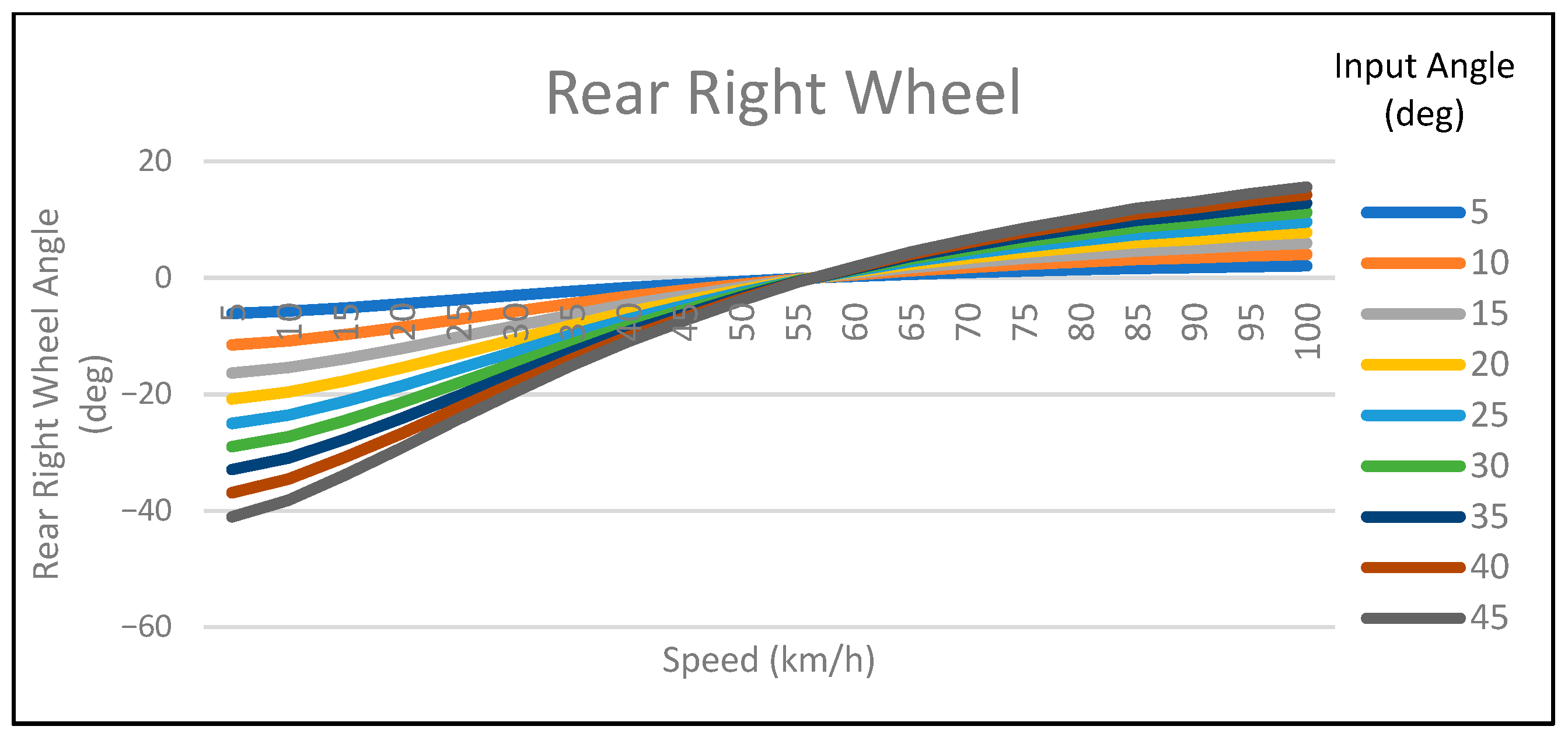
2. Steering Geometry Calculations
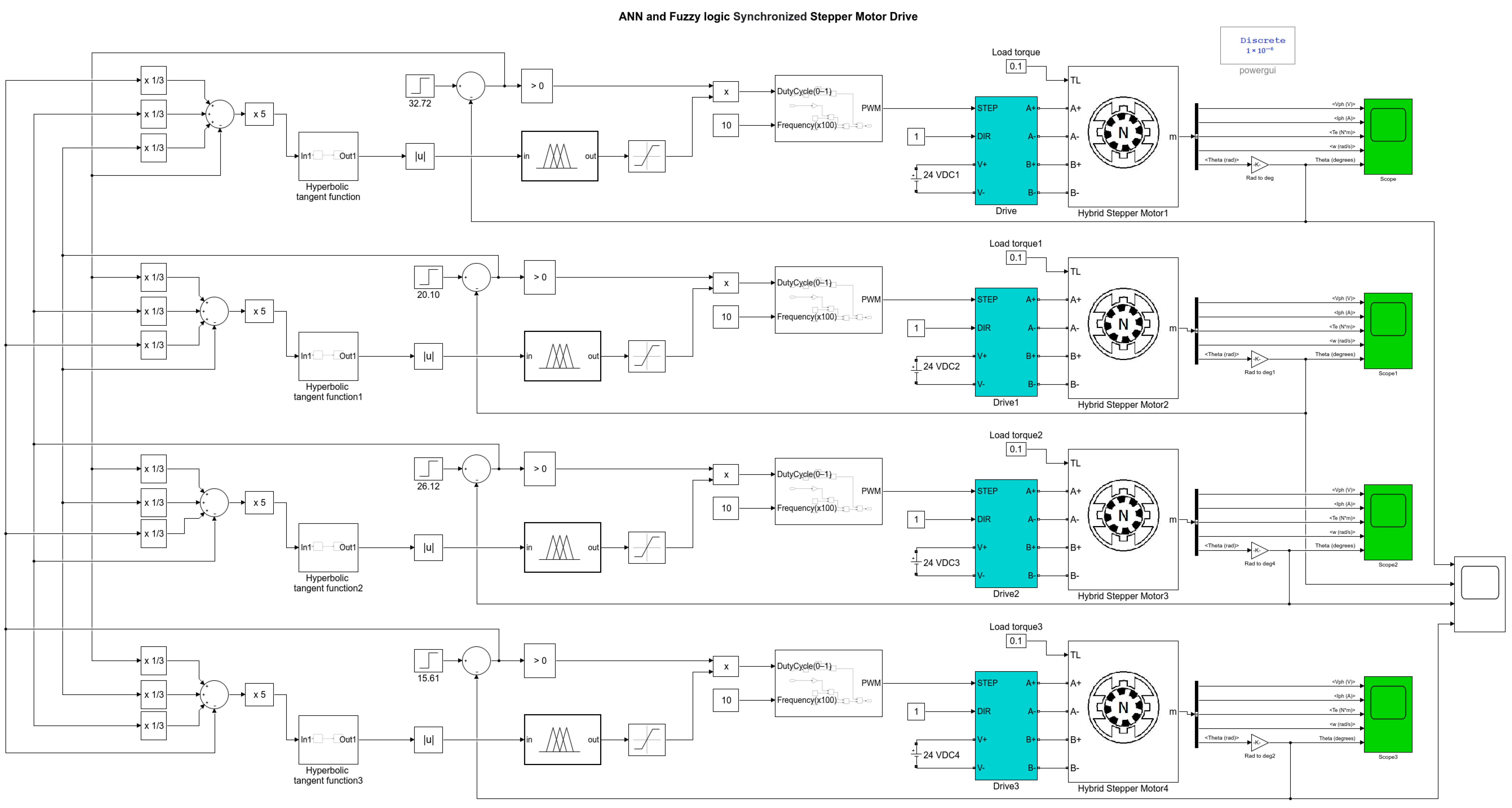
3. Mathematical Modelling of a Hybrid Stepper Motor
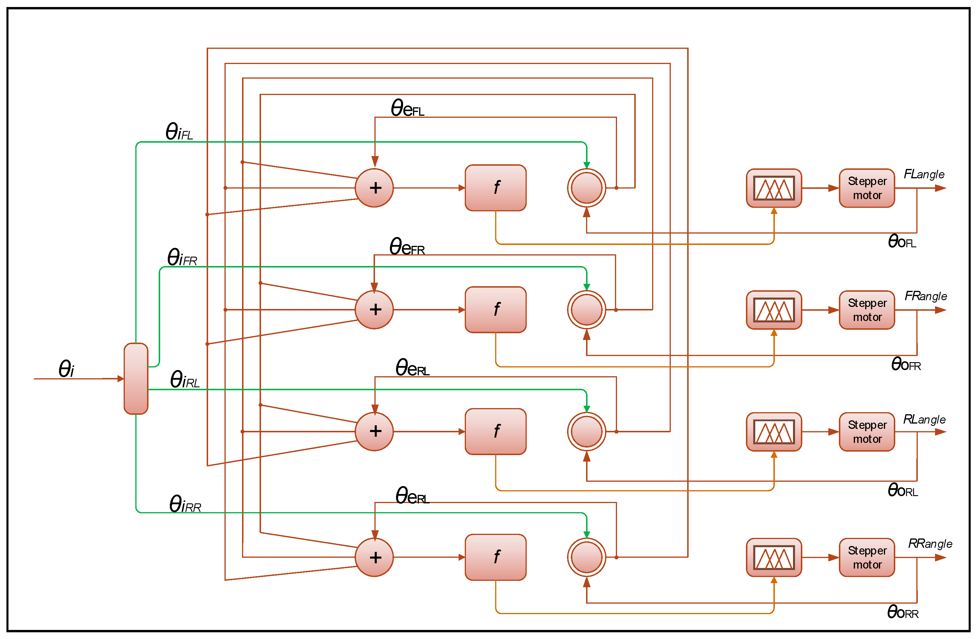
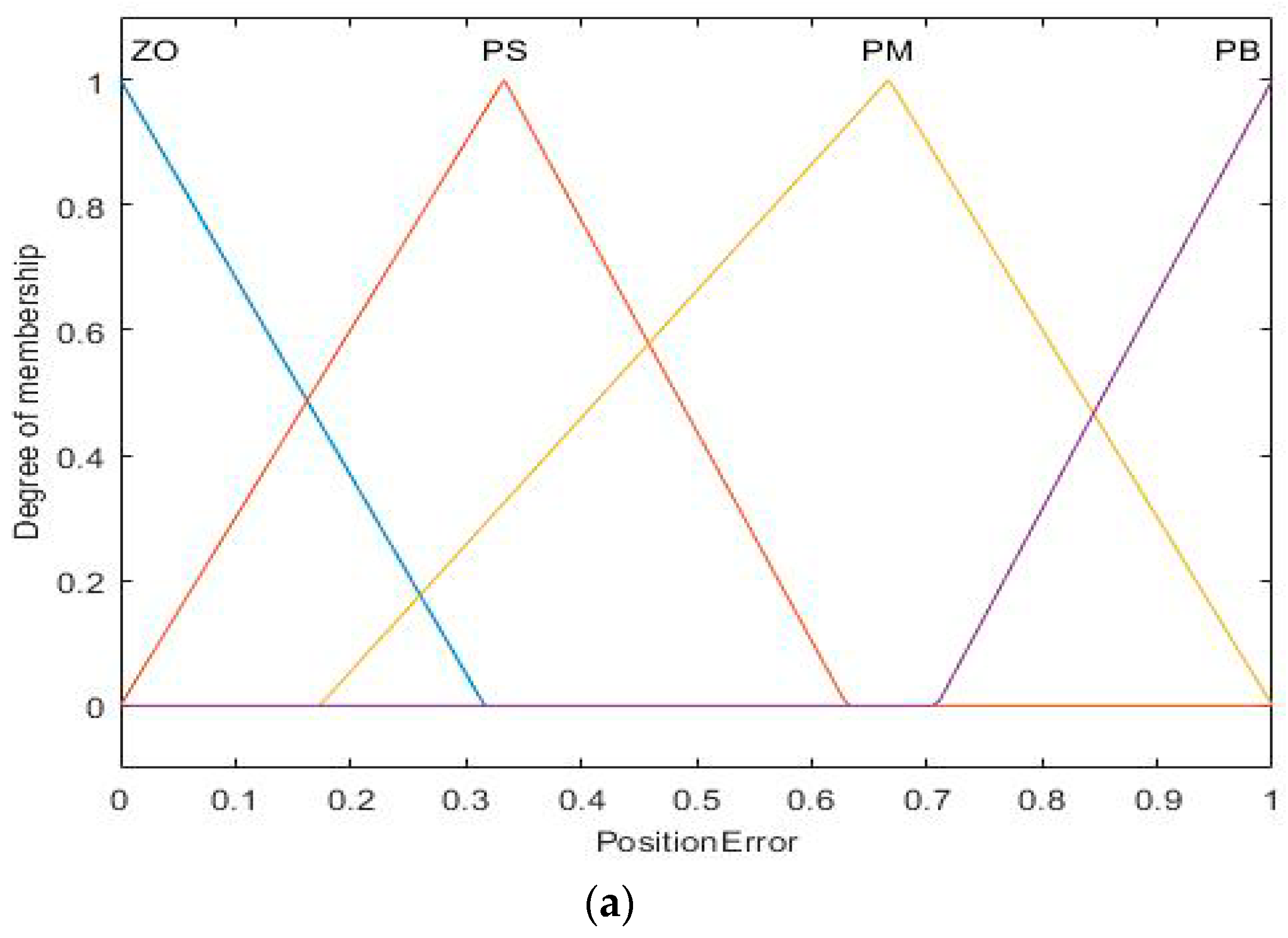
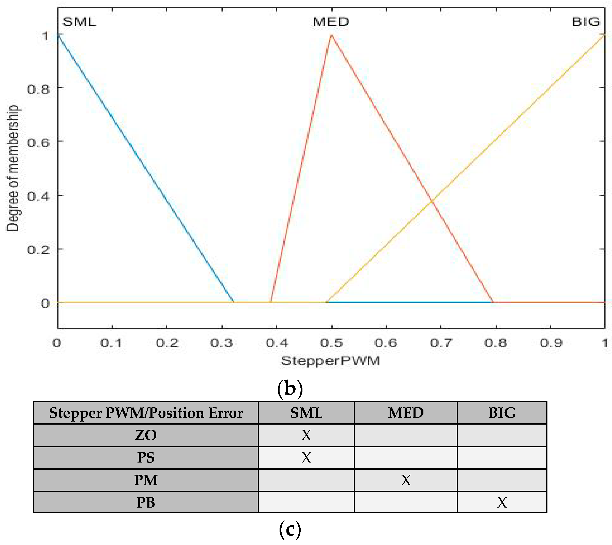
4. Controller Design Strategy
5. Simulation and Results
- ▪
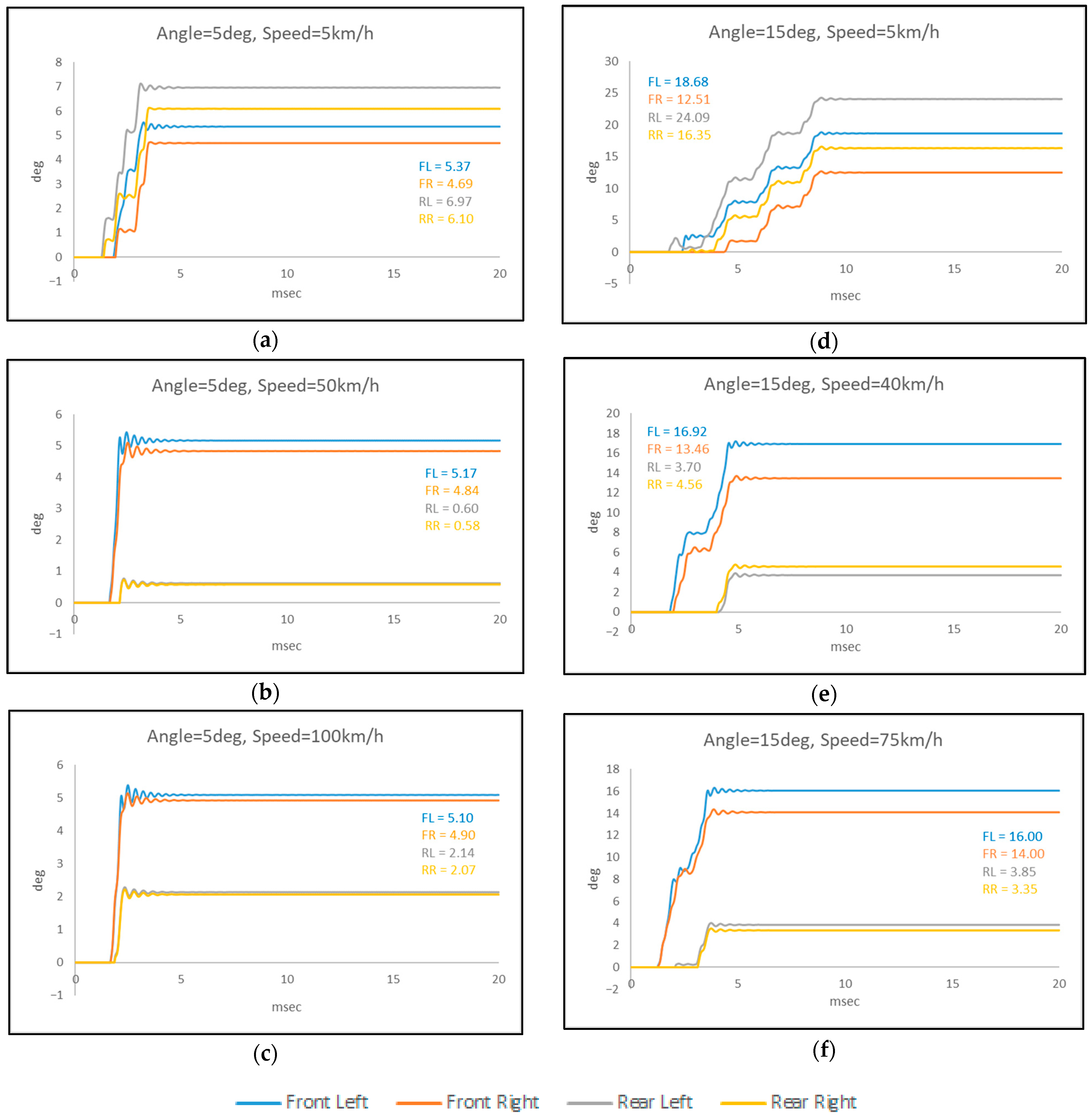
- Step response for angle = 5 deg and velocity = 5 km/h: the difference in angles between all wheels is small, in the order of 1 to 2 degrees. Rotation starts almost simultaneously, but there is a small lag in the front wheels of 0.5 ms, and a small ringing is observed before the steady state. The steady state is reached in about 2.5 ms.
- ▪
- Step response for angle = 5 deg and velocity = 50 km/h: the difference in angle between the front wheels is very small, which is also true for the rear wheels. The angle difference between the front and rear wheels is about 4.5 degrees. The rotation starts almost simultaneously, but there is a slight lag in the rear wheels of 0.5 ms, and there is ringing before the steady state. The steady state is reached in about 2.5 ms.
- ▪
- Step response for angle = 5 deg and velocity = 100 km/h: the difference in angle between the front wheels is very small, which is also true for the rear wheels. The difference between the front and rear wheels is about 3 degrees. The rotation starts almost simultaneously, and a ringing is observed before the steady state. The steady state is reached in about 2.5 ms.
- ▪
- Step response for angle = 15 deg and velocity = 5 km/h: the difference in wheel angles has a constant deviation of about 6 degrees from wheel to wheel. The start of rotation shows a lag of 0.5 ms from wheel to wheel. A small ringing (much smaller than the 5 deg case) is observed before the steady state. The steady state is reached in about 9 ms.
- ▪
- Step response for angle = 15 deg and velocity = 40 km/h: the difference in angle between the front wheels is in the order of 3 degrees, while for the rear wheels the difference is negligible. The difference between the front and rear wheels is about 10–12 degrees. The start of rotation of the rear wheels shows a delay of about 2 ms which is justified because of the large angle deviation. A small ringing (much smaller than the 5 deg case) is observed before the steady state. The steady state is reached in about 5 ms.
- ▪
- Step response for angle = 15 deg and velocity = 75 km/h: the difference in angle between the front wheels is 2 degrees, while in the rear wheels the difference is very small. The difference between the front and rear wheels is about 10–12 degrees. The start of the rotation of the rear wheels shows a delay of about 2 ms which is justified because of the large difference in angle. A small ringing (much smaller than the 5 deg case) is observed before the steady state. The steady state is reached in about 4 ms.
- ▪
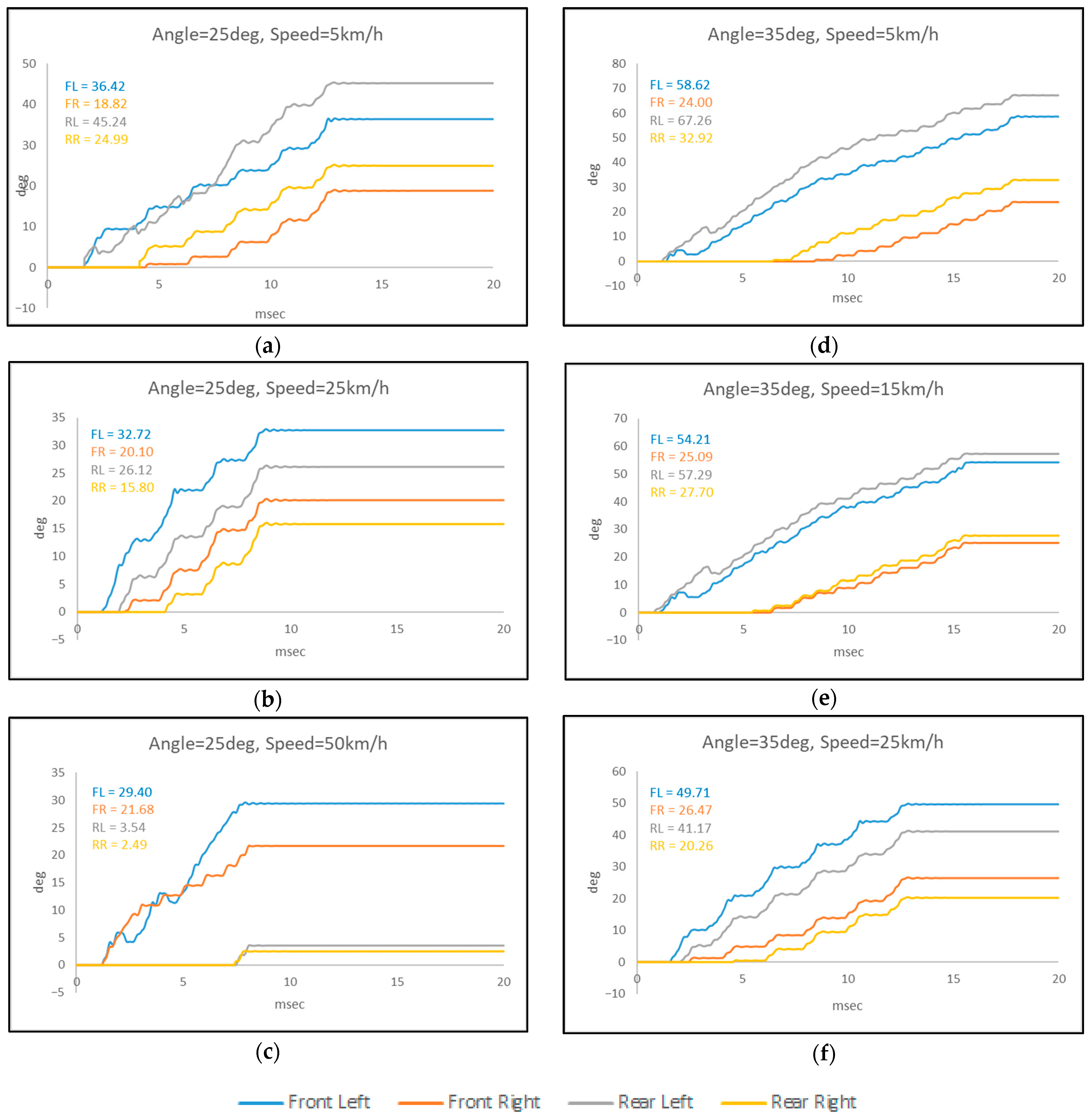
- Step response for angle = 25 deg and velocity = 5 km/h: the difference in angle between the front wheels is about 11 degrees, while for the rear wheels the difference is about 6 degrees. The difference between the front and rear wheels is approximately 9–10 degrees. The start of rotation of the rear wheels shows a delay of about 2 ms which is justified because of the large angle deviation. A subtle ringing is observed before the steady state. The steady state is reached in about 13 ms.
- ▪
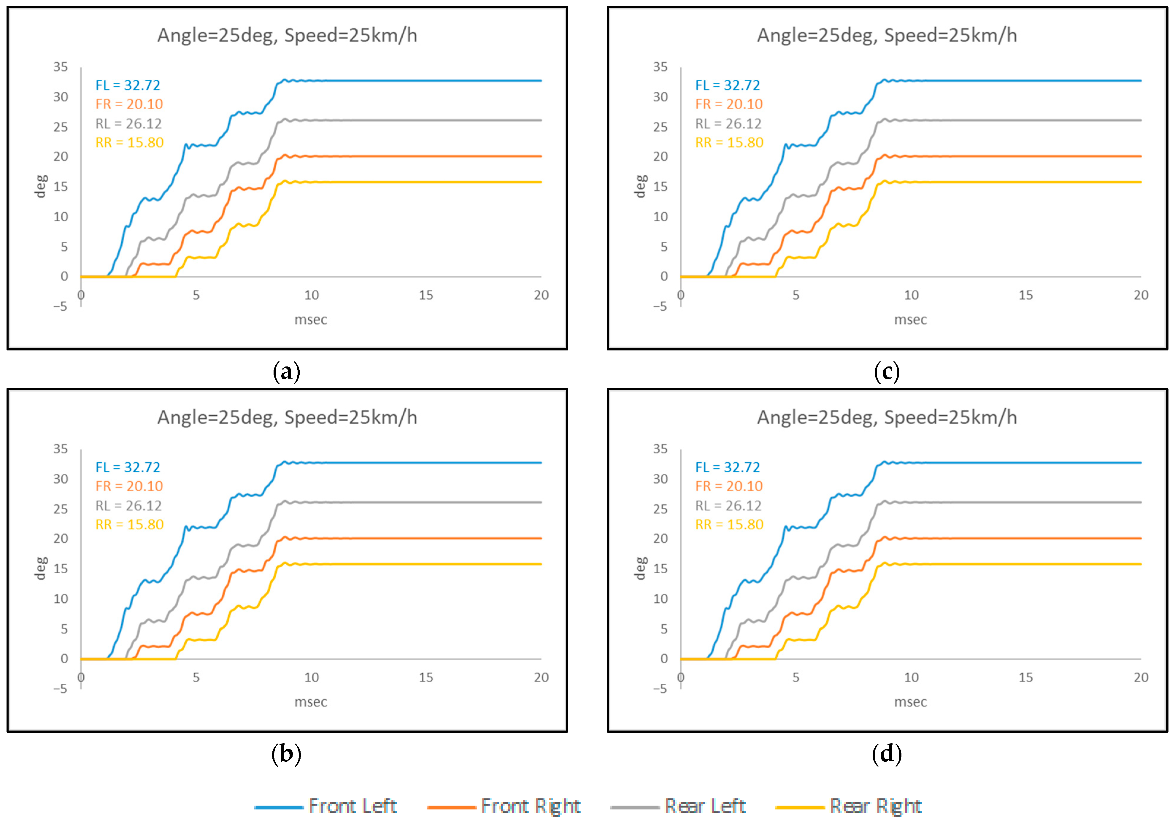
- Step response for angle = 25 deg and velocity = 25 km/h: the difference in wheel angles has a constant deviation of about 5 to 6 degrees from wheel to wheel, while the onset of rotation shows a lag of about 1 to 2 ms from wheel to wheel. A subtle ringing is observed before the steady state. The steady state is reached in about 9 ms.
- ▪
- Step response for angle = 25 deg and velocity = 50 km/h: the difference in angle between the front wheels is about 8 degrees, while for the rear wheels the difference is very small. The difference between the front and rear wheels is approximately 22 degrees. The start of rotation of the rear wheels shows a delay of about 6 ms which is justified because of the large angle deviation. A subtle oscillation is observed before the steady state. The steady state is reached in about 8 ms.
- ▪
- Step response for angle = 35 deg and velocity = 5 km/h: the difference in angle between the front wheels is about 11 degrees, while for the rear wheels the difference is about 7 degrees. The difference between the front and rear wheels is approximately 35 degrees. The start of rotation of the rear wheels shows a delay of about 6 ms which is justified because of the large angle deviation. No ringing is observed before the steady state. The steady state is reached in about 18 ms.
- ▪
- Step response for angle = 35 deg and velocity = 15 km/h: the difference in angle between the front and rear wheels is about 3 degrees. The difference between the front and rear wheels is approximately about 30 degrees. The start of rotation of the rear wheels shows a delay of about 5 ms which is justified because of the large angle deviation. No ringing is observed before the steady state. The steady state is reached in about 16 ms.
- ▪
- Step response for angle = 35 deg and velocity = 25 km/h: the difference in angle between the front wheels is about 8 degrees, while for the rear wheels the difference is about 6 degrees. The difference between the front and rear wheels is approximately 22 degrees. The start of rotation of the rear wheels shows a delay of about 3 ms which is justified because of the large angle deviation. No ringing is observed before the steady state. The steady state is reached in about 13 ms.
- ▪
- The shorter the rotation, which is more prominently observed in responses below 5 ms, the greater the ringing before reaching a steady state. In longer response times, this phenomenon is eliminated, and the system smoothly reaches a steady state.
- ▪
- The greater the difference in the angles between the wheels, the slower the onset of the response in the wheels that have the smallest angle to turn.
- ▪
- The larger the angle a wheel needs to turn, the more time it requires. The longest response is observed in the combination of angle = 35 deg and velocity = 5 km/h, taking 18 ms, while the shortest is in the combination of angle = 5 deg and velocity = 100 km/h, taking 2 ms.
- ▪
- For the same angle of rotation, the higher the speed of the vehicle, the sooner the steady state is reached.
- ▪
- In all combinations of angle and velocity, all wheels, regardless of their load, reach a steady state simultaneously.
6. Conclusions
- ✓
- Stability: The proposed control scheme ensures high precision and accuracy in steering control, guaranteeing a level of stability that surpasses existing systems.
- ✓
- Efficiency: It optimizes energy consumption, leading to a notable increase in the overall efficiency of 4WIS systems in EVs.
- ✓
- Practicality: Beyond theoretical applications, this method is designed with practicality in mind, opening doors for real-world implementation in electric vehicles.
- ➢
- The application of neural networks greatly simplifies the computational power of the fuzzy logic controller.
- ➢
- The controller of each wheel is able to monitor the position of the other wheels, thus providing the vehicle with safety against derailment.
- ➢
- Finally, the proposed control system achieves the required response of the vehicle angle to the wheels even in the case of uneven and abrupt load changes.
Author Contributions
Funding
Data Availability Statement
Conflicts of Interest
References
- Furukawa, Y.; Yuhara, N.; Sano, S.; Takeda, H.; Matsushita, Y. A Review of Four-Wheel Steering Studies from the Viewpoint of Vehicle Dynamics and Control. Veh. Syst. Dyn. 1989, 18, 151–186. [Google Scholar] [CrossRef]
- Shibahata, Y.; Irie, N.; Itoh, H.; Nakamura, K. The Development of an Experimental Four-Wheel-Steering Vehicle. SAE Trans. 1986, 95, 862–869. [Google Scholar]
- Sano, S.; Furukawa, Y.; Shiraishi, S. Four Wheel Steering System with Rear Wheel Steer Angle Controlled as a Function of Steering Wheel Angle; SAE International: Warrendale, PA, USA, 1986; p. 860625. [Google Scholar]
- Zheng, H.; Yang, S.; Li, B. Optimization Control for 4WIS Electric Vehicle Based on the Coincidence Degree of Wheel Steering Centers. SAE Int. J. Veh. Dyn. Stab. NVH 2018, 2, 169–184. [Google Scholar] [CrossRef]
- Chen, H.; Chen, S.; Zhou, R.; Huang, X.; Zhu, S. Research on Four-wheel Independent Steering Intelligent Control Strategy Based on Minimum Load. Concurr. Comput. Pract. Exp. 2021, 33, e6145. [Google Scholar] [CrossRef]
- Yin, D.; Wang, J.; Du, J.; Chen, G.; Hu, J.-S. A New Torque Distribution Control for Four-Wheel Independent-Drive Electric Vehicles. Actuators 2021, 10, 122. [Google Scholar] [CrossRef]
- Cao, Y.; Qiao, M. Application of Fuzzy Control in Four Wheel Steering Control System. In Proceedings of the 2017 International Conference on Advanced Mechatronic Systems (ICAMechS), Xiamen, China, 6–9 December 2017; IEEE: Xiamen, China, 2017; pp. 62–66. [Google Scholar]
- Hakima, A.; Ameli, S. Designing a Fuzzy Logic Controller to Adjust the Angle of Tires in Four Wheel Steering Vehicles. In Proceedings of the 2010 11th International Conference on Control Automation Robotics & Vision, Singapore, 7–10 December 2010; pp. 2208–2213. [Google Scholar]
- Tian, J.; Tong, J.; Luo, S. Differential Steering Control of Four-Wheel Independent-Drive Electric Vehicles. Energies 2018, 11, 2892. [Google Scholar] [CrossRef]
- Özatay, E. Fuzzy Logic Control of Four-Wheel Steering System. Master Thesis, Middle East Technical University, Ankara, Turkey, 2003. [Google Scholar]
- Haytham, A.; Elhalwagy, Y.Z.; Wassal, A.; Darwish, N.M. Modeling and Simulation of Four-Wheel Steering Unmanned Ground Vehicles Using a PID Controller. In Proceedings of the 2014 International Conference on Engineering and Technology (ICET), Cairo, Egypt, 19–20 April 2014; pp. 1–8. [Google Scholar]
- Ariff, M.H.M.; Zamzuri, H.; Nordin, M.A.M.; Yahya, W.J.; Mazlan, S.A.; Rahman, M.A.A. Optimal Control Strategy for Low Speed and High Speed Four-Wheel-Active Steering Vehicle. J. Mech. Eng. Sci. 2015, 8, 1516–1528. [Google Scholar] [CrossRef]
- Khan, M.A.; Aftab, M.F.; Ahmed, E.; Youn, I. Robust Differential Steering Control System for an Independent Four Wheel Drive Electric Vehicle. Int. J. Automot. Technol. 2019, 20, 87–97. [Google Scholar] [CrossRef]
- Zhou, P.; Ren, C.; Meng, L.; Chen, Y.; Nan, Y. Study on the Multi-Mode Optimal Steering Control System for an Independent Four Wheel Drive Electric Vehicle. Appl. Sci. 2022, 12, 7037. [Google Scholar] [CrossRef]
- Arifin, B.; Suprapto, B.Y.; Prasetyowati, S.A.D.; Nawawi, Z. Steering Control in Electric Power Steering Autonomous Vehicle Using Type-2 Fuzzy Logic Control and PI Control. World Electr. Veh. J. 2022, 13, 53. [Google Scholar] [CrossRef]
- Tan, X.; Liu, D.; Xiong, H. Optimal Control Method of Path Tracking for Four-Wheel Steering Vehicles. Actuators 2022, 11, 61. [Google Scholar] [CrossRef]
- Jeong, Y.; Yim, S. Integrated Path Tracking and Lateral Stability Control with Four-Wheel Independent Steering for Autonomous Electric Vehicles on Low Friction Roads. Machines 2022, 10, 650. [Google Scholar] [CrossRef]
- Wang, J.; Wang, Q.; Jin, L.; Song, C. Independent Wheel Torque Control of 4WD Electric Vehicle for Differential Drive Assisted Steering. Mechatronics 2011, 21, 63–76. [Google Scholar] [CrossRef]
- Pham, D.-A.; Han, S.-H. Design of Combined Neural Network and Fuzzy Logic Controller for Marine Rescue Drone Trajectory-Tracking. J. Mar. Sci. Eng. 2022, 10, 1716. [Google Scholar] [CrossRef]
- Zhang, Q.; Fu, X. A Neural Network Fuzzy Energy Management Strategy for Hybrid Electric Vehicles Based on Driving Cycle Recognition. Appl. Sci. 2020, 10, 696. [Google Scholar] [CrossRef]
- Kosmidis, A.N.; Ioannidis, G.C.; Vokas, G.A.; Psomopoulos, C.S. Analysis and Simulation of Four-Wheel Independent Steering Control for Electric Vehicles. In Proceedings of the Technologies and Materials for Renewable Energy, Environment and Sustainability: TMREES20, Athens, Greece, 25–27 June 2020; p. 020046. [Google Scholar]
- Li, H.; Gupta, M. Fuzzy Logic and Intelligent Systems; Kluwer Academic Publishers: London, UK, 1995. [Google Scholar]
- Sakti, I. Methodology of Fuzzy Logic with Mamdani Fuzzy Models Applied to the Microcontroller. In Proceedings of the 2014 1st International Conference on Information Technology, Computer, and Electrical Engineering, Semarang, Indonesia, 8 November 2014; pp. 93–98. [Google Scholar]
- Kickert, W.J.M.; Mamdani, E.H. Analysis of a Fuzzy Logic Controller. In Readings in Fuzzy Sets for Intelligent Systems; Elsevier: Amsterdam, The Netherlands, 1993; pp. 290–297. ISBN 9781483214504. [Google Scholar]

| Phase Number | 2 |
| Inductance of Winding (H) | 1.4 × 10⁻³ |
| Resistance of Winding (Ohm) | 0.7 |
| Angle of Step (degree) | 1.8 |
| Max Flux Linkage (Vs) | 0.005 |
| Max Detent Torque (N·m) | 0.002 |
| Total inertia (kg·m·m) | 1.2 × 10⁻⁷ |
| Total friction (N·m·s) | 1 × 10⁻⁴ |
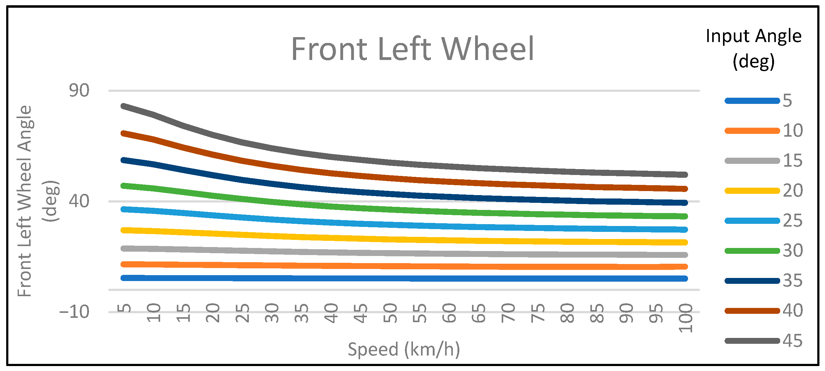
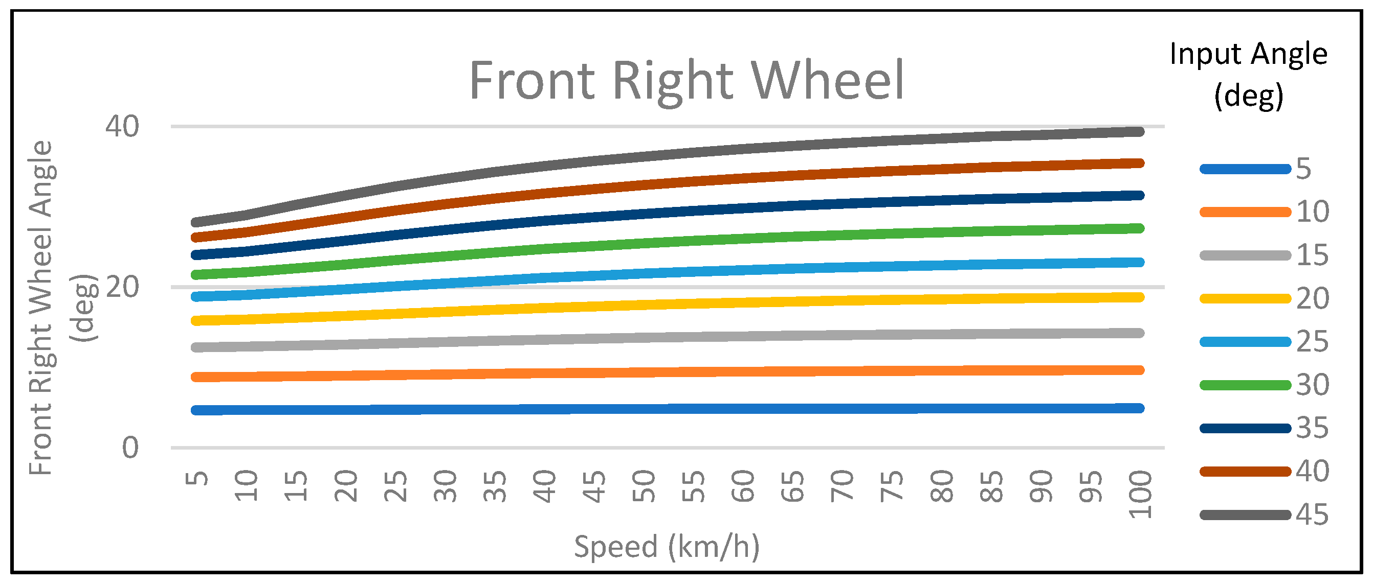
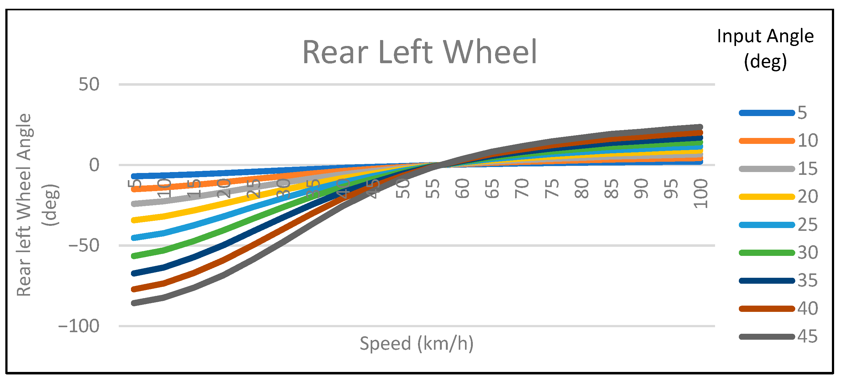
| Input Angle (deg) | Vehicle Speed (km/h) | Front Left Angle (deg) | Front Rear Angle (deg) | Rear Left Angle (deg) | Rear Right Angle (deg) |
|---|---|---|---|---|---|
| 5 | 5 | 5.36 | 4.69 | −6.97 | −6.10 |
| 5 | 50 | 5.17 | 4.84 | −0.61 | −0.57 |
| 5 | 100 | 5.09 | 4.92 | 2.13 | 2.06 |
| 15 | 5 | 18.68 | 12.51 | −24.09 | −16.35 |
| 15 | 40 | 16.92 | 13.46 | −3.70 | −4.57 |
| 15 | 75 | 16.05 | 14.08 | 3.85 | 3.35 |
| 25 | 5 | 36.42 | 18.82 | −45.24 | −24.99 |
| 25 | 25 | 34.72 | 19.36 | −37.43 | −21.21 |
| 25 | 50 | 32.72 | 20.10 | −26.12 | −15.61 |
| 35 | 5 | 58.62 | 24.00 | −67.25 | −32.92 |
| 35 | 15 | 54.21 | 25.09 | −57.27 | −27.71 |
| 35 | 25 | 49.71 | 26.47 | −41.17 | −20.26 |
Disclaimer/Publisher’s Note: The statements, opinions and data contained in all publications are solely those of the individual author(s) and contributor(s) and not of MDPI and/or the editor(s). MDPI and/or the editor(s) disclaim responsibility for any injury to people or property resulting from any ideas, methods, instructions or products referred to in the content. |
© 2023 by the authors. Licensee MDPI, Basel, Switzerland. This article is an open access article distributed under the terms and conditions of the Creative Commons Attribution (CC BY) license (https://creativecommons.org/licenses/by/4.0/).
Share and Cite
Kosmidis, A.; Ioannidis, G.; Vokas, G.; Kaminaris, S. A Novel Real-Time Robust Controller of a Four-Wheel Independent Steering System for EV Using Neural Networks and Fuzzy Logic. Mathematics 2023, 11, 4535. https://doi.org/10.3390/math11214535
Kosmidis A, Ioannidis G, Vokas G, Kaminaris S. A Novel Real-Time Robust Controller of a Four-Wheel Independent Steering System for EV Using Neural Networks and Fuzzy Logic. Mathematics. 2023; 11(21):4535. https://doi.org/10.3390/math11214535
Chicago/Turabian StyleKosmidis, Alexis, Georgios Ioannidis, Georgios Vokas, and Stavros Kaminaris. 2023. "A Novel Real-Time Robust Controller of a Four-Wheel Independent Steering System for EV Using Neural Networks and Fuzzy Logic" Mathematics 11, no. 21: 4535. https://doi.org/10.3390/math11214535
APA StyleKosmidis, A., Ioannidis, G., Vokas, G., & Kaminaris, S. (2023). A Novel Real-Time Robust Controller of a Four-Wheel Independent Steering System for EV Using Neural Networks and Fuzzy Logic. Mathematics, 11(21), 4535. https://doi.org/10.3390/math11214535