Review

A High–Order WENO Scheme Based on Different Numerical Fluxes for the Savage–Hutter Equations

1
College of Civil Engineering & Architecture, China Three Gorges University, Yichang 443002, China
2
Three Gorges Mathematical Research Center, China Three Gorges University, Yichang 443002, China
3
College of Science, China Three Gorges University, Yichang 443002, China
*
Author to whom correspondence should be addressed.
These authors contributed equally to this work.
Mathematics 2022, 10(9), 1482; https://doi.org/10.3390/math10091482
Submission received: 7 March 2022 / Revised: 19 April 2022 / Accepted: 25 April 2022 / Published: 29 April 2022
(This article belongs to the Special Issue Numerical Methods for Computational Fluid Dynamics)

Abstract

:
The study of rapid free surface granular avalanche flows has attracted much attention in recent years, which is widely modeled using the Savage–Hutter equations. The model is closely related to shallow water equations. We employ a high-order shock-capturing numerical model based on the weighted essential non-oscillatory (WENO) reconstruction method for solving Savage–Hutter equations. Three numerical fluxes, i.e., Lax–Friedrichs (LF), Harten–Lax–van Leer (HLL), and HLL contact (HLLC) numerical fluxes, are considered with the WENO finite volume method and TVD Runge–Kutta time discretization for the Savage–Hutter equations. Numerical examples in 1D and 2D space are presented to compare the resolution of shock waves and free surface capture. The numerical results show that the method proposed provides excellent performance with high accuracy and robustness.

1. Introduction

Granular flows, such as landslides, debris flow, and snow avalanches, are widely encountered in mountainous areas and are very dangerous disasters. It is impossible to rely solely on engineering measures to prevent and control these disasters. Understanding granular mass flow is the foundation of the prediction and control of these disasters. Thus, over recent decades, the study of granular flows has attracted much attention. In the pioneering works of Savage and Hutter, a mathematical model to study the motion of a finite mass of granular material flowing down a rough incline was proposed, in which the granular material was treated as an incompressible continuum [1,2,3]. They derived their model by integrating the Navier–Stokes equations and assuming a Coulomb friction law. Later, this model was extended to three spatial dimensions with curvilinear coordinates [4,5,6], which may be applied to study natural disasters such as landslides and debris flows [7]. The Savage–Hutter model was verified to be in excellent agreement with laboratory experiments [3,8]. For more details on the Savage–Hutter model, see [3,8,9,10,11,12].
Although the Savage–Hutter equations have a very similar mathematical structure to the shallow water equations, the constitutive properties significantly complicate the model by introducing a highly nonlinear earth pressure coefficient into the equations. Thus, it is difficult to obtain the exact solution of Savage–Hutter equations in general. To better understand the properties of these flows, a powerful and high–resolution numerical method is still needed. Numerical methods for the Savage–Hutter model may be dated back to the works in [1,13], using finite difference methods in a Lagrangian moving mesh, which are not able to capture shock waves. Later on, regardless of the Savage–Hutter model or other avalanches of granular flow models, Godunov–type schemes were commonly used in the literature [14,15,16,17,18,19,20], considering that most of them make use of the hyperbolic nature of the depth–averaged equations. Tai et al. [21,22] proposed a non–oscillatory central difference (NOC) scheme with a TVD limiter or WENO cell reconstruction for the one-dimensional Savage–Hutter equations. Wang et al. [15] systematically studied several numerical methods for solving two–dimensional Savage–Hutter equations. In their work, traditional central and upstream difference schemes, high–resolution NOC schemes, several TVD limiters, and ENO cell reconstruction schemes were used and compared. Later, Chiou et al. [16] employed the NOC scheme with the Minmod TVD limiter in solving the Savage–Hutter equations to study the influence of obstacles on rapid granular flows. Vollmöller [19] developed a wave propagation method based on HLL or HLLC approximate Riemann solvers for the solution of Savage–Hutter equations. Cui [17] proposed four different finite difference TVD methods based on the NOC scheme for simulating granular avalanches around obstacles. Zhai et al. [18] applied the monotone upstream–centered schemes for conservation laws (MUSCLs) reconstruction with an HLLC approximate Riemann solver to solve the Savage–Hutter equations based on a GPU. In recent years, Yavari-Ramshe et al. [23] introduced a well–balanced finite volume scheme based on the Q–scheme of Roe to solve the Savage–Hutter model. So far, most of the numerical schemes for solving the Savage–Hutter equations have achieved at most second–order accuracy to our best knowledge, and there are only a few reports of second–order schemes for these equations [15,16,17,18,21,22]. In fact, some high–resolution schemes, such as the WENO schemes, have already been developed as mature tools in the numerical method of the hyperbolic conservation law. WENO schemes use the idea of an adaptive stencil in the reconstruction procedure based on the local smoothness of the numerical solution to automatically achieve high–order accuracy and remain non–oscillatory near discontinuities [24,25]. For more details and applications of WENO schemes, see [26,27,28,29,30,31].
Recently, we [32] showed an interesting numerical phenomenon for solving Savage–Hutter equations on unstructured grids. That is, though this model lacks rotational invariance and is not always hyperbolic, the numerical scheme still gives satisfactory results on unstructured grids. This encouraged us to check what would happen if a high–order and high–resolution scheme is applied to solve these equations. The WENO scheme is definitely the first candidate for us to investigate. Our aim is to solve the Savage–Hutter equations using a WENO scheme higher than second–order accuracy.
For the Savage–Hutter equations, it is impossible to obtain the exact Riemann solution, and one has to use an appropriate approximate Riemann solver. Most of the WENO schemes usually use the Lax–Friedrichs (LF) numerical flux due to its simplicity. However, there are many other numerical fluxes based on approximate Riemann solvers such as HLL, HLLC, and so on. For details on approximate Riemann solvers for hyperbolic conservation laws, see, e.g., the book of Toro [33,34]. The investigation of different numerical fluxes is an important component of WENO schemes for solving the Savage–Hutter equations. Thus, in this work, we try to solve the Savage–Hutter equations by using the WENO methods based on LF, HLL, and HLLC numerical fluxes and examine if there is a more appropriate numerical flux method.
The rest of the paper is organized as follows. In Section 2, the Savage–Hutter equations in a conservative form in curvilinear coordinates are briefly introduced. In Section 3, we give the details of our numerical scheme. It is based on the finite volume method with an approximate Riemann solver and WENO reconstruction. Three approximate Riemann solvers, the LF, HLL, and HLLC solvers, are used. Additionally, we give a brief review of the WENO reconstruction. In Section 4, five numerical tests including one–dimensional and two–dimensional cases are illustrated, and a short conclusion in Section 5 closes the paper.

2. Governing Equations

There are various forms of the Savage–Hutter equations according to different coordinate systems and a detailed derivation of these different versions of Savage–Hutter equations was given in [8]. In this work, the governing equations are based on an orthogonal curvilinear coordinate system along a non–erodible bed to take its curvature into account (see Figure 1). The curvilinear coordinate O x y z is defined on the reference surface, where the x–axis is oriented in the downslope direction, the y–axis lies in the cross–slope direction of the reference surface, and the z–axis is normal to them. The downslope inclination angle of the reference surface ζ only depends on the downslope coordinates x, that is there is no lateral variation in the y–direction; thus, it is strictly horizontal. The shallow basal topography is defined by its elevation z = z b ( x , y ) above the curvilinear reference surface.
The corresponding non–dimensionless Savage–Hutter equations in conservation law form in two–dimensional vector notation are
U t + F ( U ) x + G ( U ) y = S ( U ) ,
where U = ( h , h u , h v ) T denotes the vector of conservative variables, F , G represent the physical fluxes in the x– and y–directions, respectively, and S is the source term. They are
F = h u h u 2 + 1 2 β x h 2 h u v , G = h v h u v h v 2 + 1 2 β y h 2 , S = 0 h s x h s y ,
in which h is the avalanche depth in the z–direction and u , v are the depth–averaged velocity components in the downslope (x) and cross-slope (y) directions, respectively. The factors β x , β y are defined as
β x = ε cos ζ K x , β y = ε cos ζ K y ,
respectively, where ε is the aspect ratio of the characteristic thickness to the characteristic downslope extent. K x , K y are the respective x, y directional earth pressure coefficients defined by the Mohr–Coulomb yield criterion and represent the ratio between the normal stress in the downslope or cross–slope direction and the vertical normal stress. Hutter et al. suggested that [4,35]
K x a c t / p a s s = 2 1 1 cos 2 ϕ cos 2 δ sec 2 ϕ 1 ,
K y a c t / p a s s = 1 2 K x + 1 ( K x 1 ) 2 + 4 tan 2 δ ,
where ϕ and δ are the internal and basal Coulomb friction angles, respectively. The subscripts “act” and “pass” denote the active (“−”) stress state corresponding to a dilatation of the material and the passive (“+”) stress state associated with a compression by
K x = K x act , u x 0 , K x pass , u x < 0 ,
K y = K y act , v y 0 , K y pass , v y < 0 .
It can be seen that the earth pressure coefficients K x , K y are assumed to be functions of the velocity gradient in this model.
The terms s x , s y are the net driving accelerations in the x–, y–directions, respectively,
s x = sin ζ u | u | tan δ ( cos ζ + λ κ u 2 ) ϵ cos ζ z b x ,
s y = v | u | tan δ ( cos ζ + λ κ u 2 ) ϵ cos ζ z b y ,
where | u | = u 2 + v 2 , κ = ζ x is the local curvature of the reference surface and λ κ is the local stretching of the curvature.
The Savage–Hutter Equation (1) can be rewritten as
U t + A U x + B U y = S ( U ) ,
with
A = F U = 0 1 0 β x h u 2 2 u 0 u v v u ,
and
B = G U = 0 0 1 u v v u β y h v 2 0 2 v .
The eigenvalues of A and B are λ 1 = u , λ 2 = v , λ 3 / 5 = u ± β x h and λ 4 / 6 = v ± β y h . It can be noted that the eigenvalues are the same as those for the shallow water equations, but differ in the gravity wave speed. The shallow water equation are hyperbolic if h > 0 , but Savage–Hutter equations may not be hyperbolic because β x and β y are dependent on the gradient of the velocity components.
Although the form of the Savage–Hutter equations is similar to that of the shallow water equations, there are many differences. The simulation of Savage–Hutter equations may be more difficult than that of shallow water equations on account of the jump in the earth pressure coefficients K x a c t / p a s s and K y a c t / p a s s , the complex source terms s x and s y , and the free surface at the front and rear margins.

3. Numerical Method

In this section, we describe the construction of a finite volume WENO scheme for the Savage–Hutter equations. In order to solve Equation (1) numerically, we discretize the computational domain [ l x , l y ] with small grid cells where l x , l y are the lengths of the domain along the x– and y–directions, respectively. Suppose N x , N y are the number of grid cells along the respective directions. The corresponding cell sizes can be obtained by Δ x = l x / N x , Δ y = l y / N y . Now, we consider a grid cell ( i , j ) centered at ( x i , y j ) and perform the volume integration of Equation (1) over the grid cell as
1 Δ x Δ y y j 1 / 2 y j + 1 / 2 x i 1 / 2 x i + 1 / 2 U t + F ( U ) x + G ( U ) y S ( U ) d x d y = 0 ,
where x i ± 1 / 2 = x i ± Δ x / 2 , y j ± 1 / 2 = y j ± Δ y / 2 correspond to the positions of the grid cell interfaces along the x– and y–directions, respectively. After some algebraic operation, Equation (2) becomes a semi–discrete finite volume conservative form of Equation (1):
d U i j d t = F ^ i + 1 / 2 , j ( U i + 1 / 2 , j , U i + 1 / 2 , j + ) F ^ i 1 / 2 , j ( U i 1 / 2 , j , U i 1 / 2 , j + ) Δ x G ^ i , j + 1 / 2 ( U i , j + 1 / 2 , U i , j + 1 / 2 + ) G ^ i , j 1 / 2 ( U i , j 1 / 2 , U i , j 1 / 2 + ) Δ y + S i j ,
where U i j is the volume average of U in the grid cell ( i , j ) and is defined as
U i j = 1 Δ x Δ y y j 1 / 2 y j + 1 / 2 x i 1 / 2 x i + 1 / 2 U d x d y ,
where F ^ i ± 1 / 2 , j and G ^ i , j ± 1 / 2 are the area-averaged fluxes of U at the grid cell interface along the x– and y–directions, respectively. U i ± 1 / 2 , j ± and U i , j ± 1 / 2 ± can be constructed through the WENO reconstruction. In the paper, the third–order WENO finite volume scheme is used for the reconstruction for both one–dimensional and two–dimensional problems. S i j is the volume average of the source term S in the grid cell ( i , j ) and is defined as
S i j = 1 Δ x Δ y y j 1 / 2 y j + 1 / 2 x i 1 / 2 x i + 1 / 2 S d x d y .
In the paper, the center of gravity rule, which is the simplest quadrature formula, is adopted to calculate the source term. The only open question is the computation of the fluxes for Equation (3). For the Savage–Hutter equations, there is no exact Riemann solver. Thus, the numerical flux based on approximate Riemann solvers will be used in this work. Meanwhile, for multi–dimensional problems, we just extend the one–dimensional methods, applied in a dimension–by–dimension fashion, i.e., to evaluate F ^ i ± 1 / 2 , j , one assumes y j is a constant, and constructs U along x only. In the following, we thus consider the one–dimensional problem to review three numerical fluxes for the Savage–Hutter equations.

3.1. The Lax–Friedrichs Flux

The LF flux is one of the simplest and most widely used, but the LF flux has the largest numerical viscosity among monotone numerical fluxes. For the Savage–Hutter equations and considering the wet/dry bed cases, the LF flux is defined by [33]
F ^ L F U L , U R = 0.5 F U L + F U R α U R U L , h L > 0 , h R > 0 , 0.5 F U L + α U L , h L > 0 , h R = 0 , 0.5 F U R α U R , h L = 0 , h R > 0 ,
where U L and U R are the left and right Riemann states for a local Riemann problem, respectively. α is taken as an upper bound over the whole line for | F ( U ) | in the scalar case or for the maximum absolute value of eigenvalues of the Jacobian for the system case.

3.2. The Harten–Lax–Van Leer Flux

The HLL flux is also simple and based on the approximate Riemann solver with a two-wave model. The HLL flux for the Savage–Hutter equations is given by [32,34]
F ^ H L L U L , U R = F U L , s L 0 , s R F U L s L F U R + s R s L U R U L s R s L , s L 0 s R , F U R , s R 0 ,
where the left wave s L and right wave s R have many possible choices. If considering the dry/wet bed cases, which are similar to the shallow water equations, the left and right wave speeds in the x-direction are expressed as [32]
s L = min u L c L h L , u c L h , h L , h R > 0 , u L c L h L , h R = 0 , u R 2 c R h R , h L = 0 ,
s R = min u L + c L h L , u + c L h , h L , h R > 0 , u L + 2 c L h L , h R = 0 , u R + c R h R , h L = 0 ,
where c L = β x L , c R = β x R and
u = 1 2 u L + u R + c L h L c R h R , h = 1 c K 1 2 ( c L h L + c R h R ) + 1 4 u L + u R 2 , K = L , R .
The wave speeds in the y–direction can be given similarly.
Of course, we can also directly use the following approach to estimate the wave speeds for simplicity [36]:
s L = min ( u L c L h L , u R c R h R ) , s R = min ( u L + c L h L , u R + c R h R ) .

3.3. The HLLC Flux

The shortcoming of HLL is a poor resolution of intermediate waves, such as shear waves and contact discontinuities. The HLLC approximate Riemann solver is a modification of the basic HLL scheme to account for the influence of intermediate waves. The HLLC flux for the Savage–Hutter equations is given by [18]
F ^ H L L C U L , U R = F U L , s L 0 , F U L + s L U L U L , s L 0 s , F U R + s R U R U R , s 0 s R , F U R , s R 0 ,
where intermediate variables in the star region of the HLLC approximate Riemann solver are
U K = h K s K u K s K s 1 s v K , K = L , R ,
in the x–direction and
U K = h K s K v K s K s 1 u K s , K = L , R ,
in the y–direction. The estimate for the middle wave is
s = s L h R u R s R s R h L u L s L h R u R s R h L u L s L ,
and the left wave s L and right wave s R are given in (4) and (5), respectively.

3.4. Review of WENO Reconstruction

The finite volume discretization of Equation (3) requires the reconstruction of the respective interface values, such as U i + 1 / 2 . In this paper, the WENO reconstruction is used. The heart of the WENO methodology is the polynomial reconstruction, and the details of the WENO method can be found in [26,37]. Here, we give a brief introduction for the one–dimensional, scaler case.
The WENO reconstruction of u i + 1 / 2 from { u i ¯ } includes the following steps:
Step 1: Reconstruct the k-th degree polynomials p j ( x ) , associated with each of the stencils S j , j = 1 , , k , and the ( 2 k ) -th degree polynomial q ( x ) , associated with the larger stencil S = S j , such that:
u ¯ i + l = 1 Δ x i + l I i + l p j ( x ) d x , l = k + j , , j ,
u ¯ i + l = 1 Δ x i + l I i + l q ( x ) d x , l = k , , k .
Step 2: Find the linear weight d 1 , , d k , such that
q x i + 1 / 2 = j = 0 k d j p j x i + 1 / 2 .
Step 3: Compute the smoothness indicators of each stencil S j by
β j = l = 1 k I i Δ x i 2 l 1 l x l p j ( x ) 2 d x , j = 1 , , k .
Step 4: Find the nonlinear weight ω j based on the smoothness indicators:
ω j = γ j j γ j , γ j = d j j ϵ + β j 2 , j = 1 , , k .
Step 5: Find the ( 2 k 1 ) -th order reconstruction
u i + 1 / 2 = j = 1 k ω j p j x i + 1 / 2 .

3.5. Time Discretization and Time Stepping

In this paper, the discretization of the ODEs (3) in time obtained from the spatial discretization using the method of lines is performed by the third–order total variation diminishing (TVD) Runge–Kutta method [37]:
U ( 1 ) = U n + Δ t L U n , U ( 2 ) = 3 4 U n + 1 4 U ( 1 ) + 1 4 Δ t L U ( 1 ) , U n + 1 = 1 3 U n + 2 3 U ( 2 ) + 2 3 Δ t L U ( 2 ) ,
where L is the spatial discretization operator and U n is the solution at time t n .
The present finite volume scheme is overall explicit and conditionally stable. In general, its stability is governed by the Courant–Friedrichs–Lewy (CFL) condition, for example, in the two–dimensional problem
CFL = Δ t max i , j u i , j + β x h i , j Δ x + v i , j + β y h i , j Δ y < 1 .
In this work, to ensure numerical stability, the CFL number was set to 0.9 for one–dimensional problems and to 0.4 for two–dimensional problems.

3.6. Some Special Treatment

Similar to the simulation of shallow water equations, there exist wet/dry tracking. In the work, the cells with avalanche depth h < h t o l = 10 4 or 10 5 are taken as dry cells in order to ensure numerical stability and avoid spurious oscillations. Meanwhile, the cell average momentum was also set to zero in this case. Additionally, if the simulation encounters some cells with avalanche depth h < 0 , we also set h = 0 in these cells.
In the context of the numerical simulation of shallow water equations, it is very important to develop a well–balanced numerical scheme. However, this may be more difficult for the Savage–Hutter equations. At the quiescent steady flow, η = h + z b C o n s t a n t due to the friction force inside the granular material for the Savage–Hutter equation. How to design a well–balanced numerical scheme is still an open problem and is out of the scope of this paper, so we only consider the case where z b = 0 .

4. Numerical Examples

In this section, we will illustrate five numerical tests to compare the performance of the aforementioned WENO finite volume methods based on the LF, HLL, and HLLC fluxes. For the convenience of the latter description, we denote the WENO with the numerical flux “X” as WENO–X, for example; WENO–LF stands for the WENO scheme with the LF flux.

4.1. Traveling Shock Wave

In this test problem, the granular flow slides down on an inclined plane, which means λ κ = 0 and z b = 0 ; meanwhile, the internal and basal friction angles are the same as the inclination angle, that is ϕ = δ = ζ = 40 . This implies s x = 0 , and the earth pressure coefficient is constant K x = K x a c t = K x p a s s . The initial condition of this test problem is defined as follows [22]:
h ( x , 0 ) = 0.3 , for 0 x < 24 , 0.9 , for 24 x < 36 .
u ( x , 0 ) = 1.3148317 , for 0 x < 24 , 0.1 , for 24 x 36 .
Figure 2 shows the depth h and the corresponding velocity u using the WENO schemes with the LF, HLL, and HLLC fluxes with 360 uniform cells at t = 3 and t = 6 , respectively. The reference solution is obtained by a first–order monotone scheme with the LF flux on a very fine mesh with 7200 uniform cells. It can be seen that the numerical results obtained by the WENO scheme with the LF, HLL, and HLLC numerical fluxes are satisfactory even though computed on a much coarser mesh. Meanwhile, it also can be noted that WENO-HLL and WENO–HLLC show good agreement with the reference solution, whereas the WENO–LF scheme shows some dissipative behavior at the discontinuity. The numerical errors and orders of accuracy based on the L 1 -norm for depth h by the WENO–LF, WENO–HLL, and WENO–HLLC schemes at t = 3 are shown in Table 1. It can be seen that the computational accuracy of WENO–HLLC and WENO–HLL is better than that of WENO–LF under the same number of mesh cells. Meanwhile, all the schemes attained the third–order accuracy in the example.

4.2. Parabolic Initial Solution

In this test problem, the parabolic avalanche body is considered to slide on an inclined flat plane in the domain pf 0 x 36 dimensionless length units with constant inclination ζ = 40 , which means λ κ = 0 and z b = 0 . The basal and internal friction angles were simultaneously selected to be 30 . The initial depth and velocity distributions are given as [22]:
h ( x , 0 ) = 1 ( ( x 4 ) / 3.2 ) 2 , for 0.8 x 7.2 , 0 , for others .
u ( x , 0 ) = 1.2 , for 0.8 x 7.2 , 0.0 , for others .
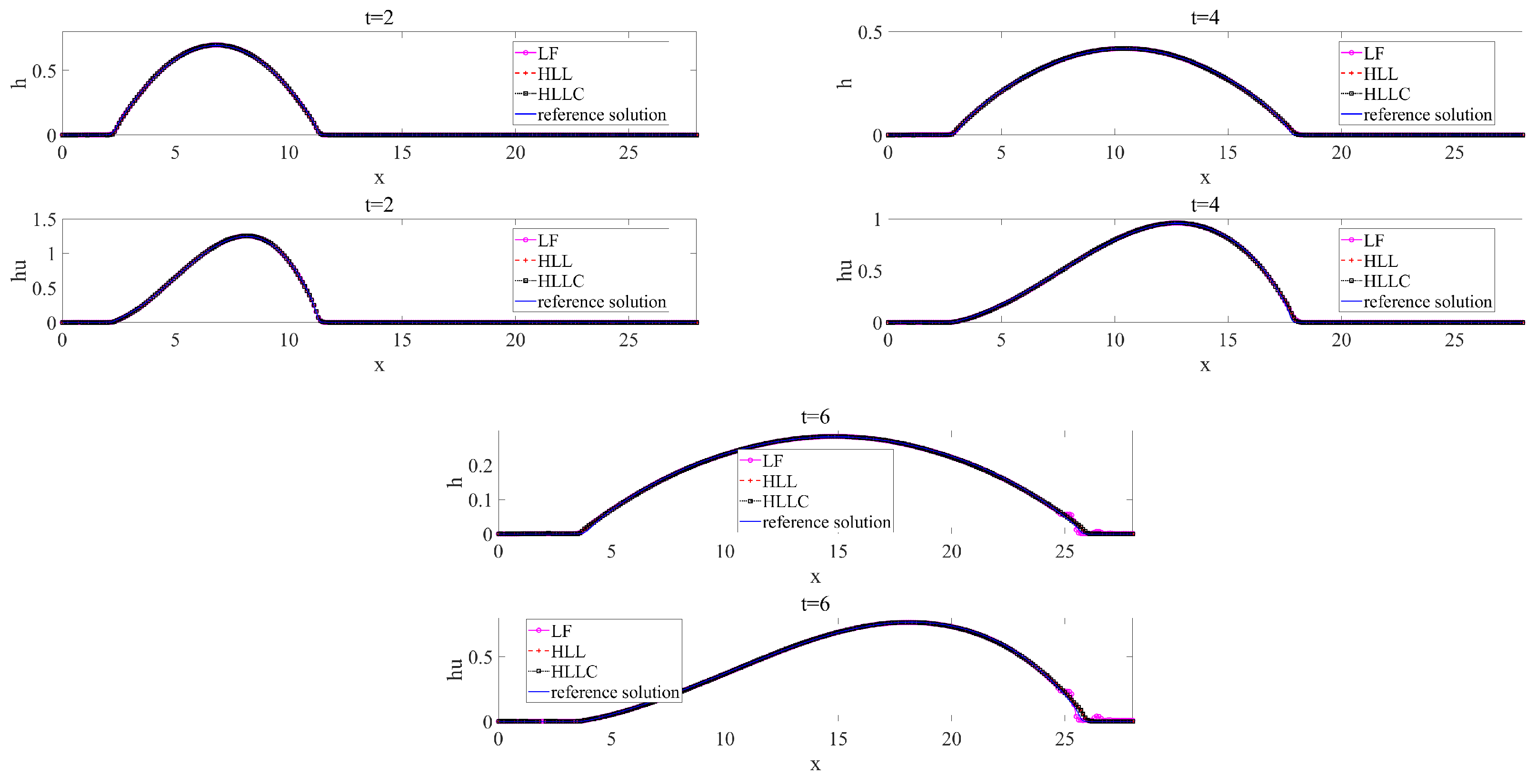
In Figure 3, the computed depth h and discharge h u of the avalanche are plotted against the numerical solution computed by the first–order monotone scheme on a mesh with 7200 uniform cells. From Figure 3, it can be seen that the results using the WENO–LF scheme are acceptable for the depth of the avalanche and the discharge at t = 2 and t = 4 , but some oscillations appear near the front of the avalanche at t = 6 . However, all results of the depth and discharge profiles computed by the WENO–HLL and WENO–HLLC schemes are in good agreement with the reference solution. In fact, the numerical results obtained by the WENO–HLL and WENO–HLLC schemes are better than those by the WENO–LF scheme.

4.3. Dam Break with Exact Solution for 1D

For the dam break problem, we consider a one–dimensional problem with exact solutions involving a constant bed slope and a Coulomb friction stress, which is often used to test the effectiveness and robustness of numerical methods. Meanwhile, this one–dimensional exact solution is also useful to check the performance of the numerical schemes in the two–dimensional case, which will be discussed later in this work. The governing equations in the one–dimensional case are given as [18,38]:
h t + ( h u ) x = 0 , ( h u ) t + ( h u 2 + 1 2 g cos ζ h 2 ) x = g h cos ζ ( tan δ tan ζ ) ,
where g is the gravitational constant, and the analytical solution of a granular dam break problem is given [18]:
( h , U ) = h 0 , 0 , χ < c 0 t , h 0 9 2 χ c 0 t 2 , 2 3 χ t + c 0 , c 0 t χ 2 c 0 t , ( 0 , 0 ) , χ > 2 c 0 t ,
where c 0 = g h 0 cos ζ and
χ = x + 1 2 g cos ζ ( tan δ tan ζ ) t 2 ,
U = u + g cos ζ ( tan δ tan ζ ) t .
The computational domain is 12.8 x 12.8 , and the initial conditions are
( h 0 , u 0 ) = ( 10 , 0 ) , x 0 , ( h 0 , u 0 ) = ( 0 , 0 ) , x > 0 ,
and ζ = 40 , δ = 24 . 5 .
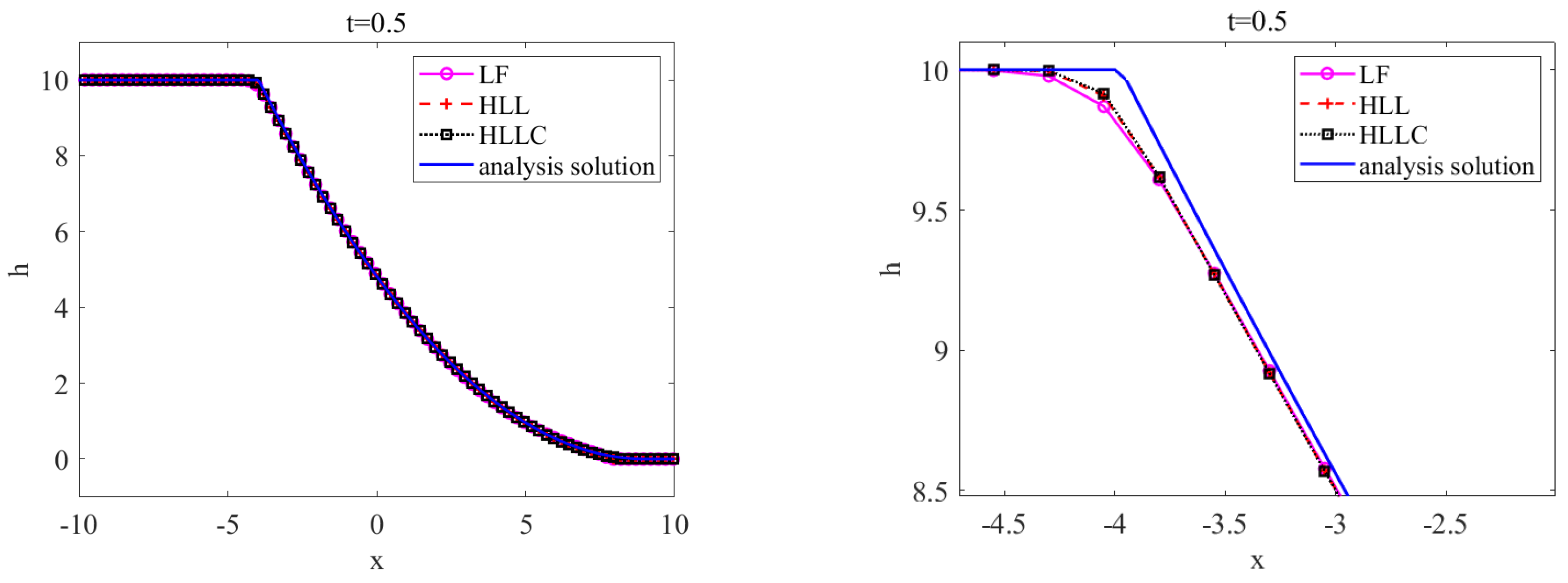
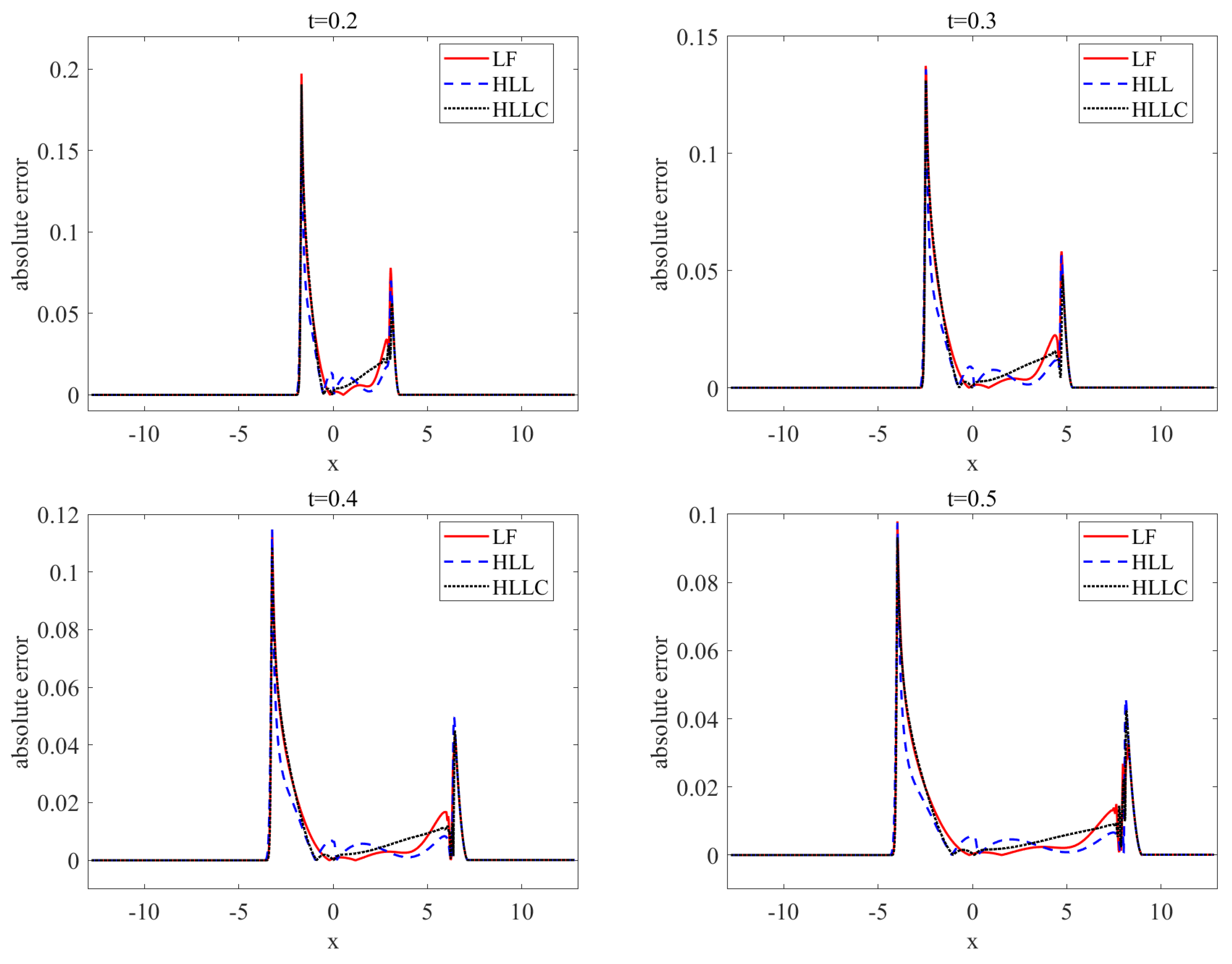
In Figure 4, the computed avalanche depth with 1024 uniform cells and three different numerical fluxes is plotted against the exact solutions at t = 0.5 . It can be seen that our numerical solutions obtained by the WENO–LF, WENO–HLL, and WENO–HLLC schemes are in very good agreement with the exact solutions, which also verifies the robustness and validity of our numerical algorithm. In order to further compare the computational accuracy of the WENO method with the three different numerical fluxes, Figure 5 shows the pointwise absolute errors of avalanche depth h with the WENO–LF, WENO–HLL, and WENO–HLLC schemes at t = 0.2 , 0.3 , 0.4 , and 0.5 . In this example, we found that the selection of s L and s R has a great influence on the calculation for the HLL flux, and Equation (6) is used to calculate the wave speed. Combining Figure 4 and Figure 5, it is not difficult to find that the numerical results computed by the WENO–HLL and WENO–HLLC schemes are better than those by the WENO–LF scheme. On the whole, the WENO–HLLC scheme is the best of the three schemes.

4.4. Dam Break with Exact Solution for 2D

In order to check the performance of the numerical schemes proposed in this work, we modified the one–dimensional dam break problem to an equivalent two–dimensional problem as in [18]. That is,
h t + ( h u ) x + ( h v ) y = 0 , ( h u ) t + ( h u 2 + 1 2 g cos ζ h 2 ) x + ( h u v ) y = g h cos ζ ( tan δ tan ζ ) , ( h v ) t + ( h u v ) x + ( h v 2 + 1 2 g cos ζ h 2 ) x = g h cos ζ ( tan δ tan ζ ) .
The computational domain is [ 12.8 , 12.8 ] × [ 1.6 , 1.6 ] , and the initial conditions are
( h 0 , u 0 , v 0 ) = ( 10 , 0 , 0 ) , x 0 , ( h 0 , u 0 , v 0 ) = ( 0 , 0 , 0 ) , x > 0 ,
and ζ = 40 , δ = 24 . 5 .
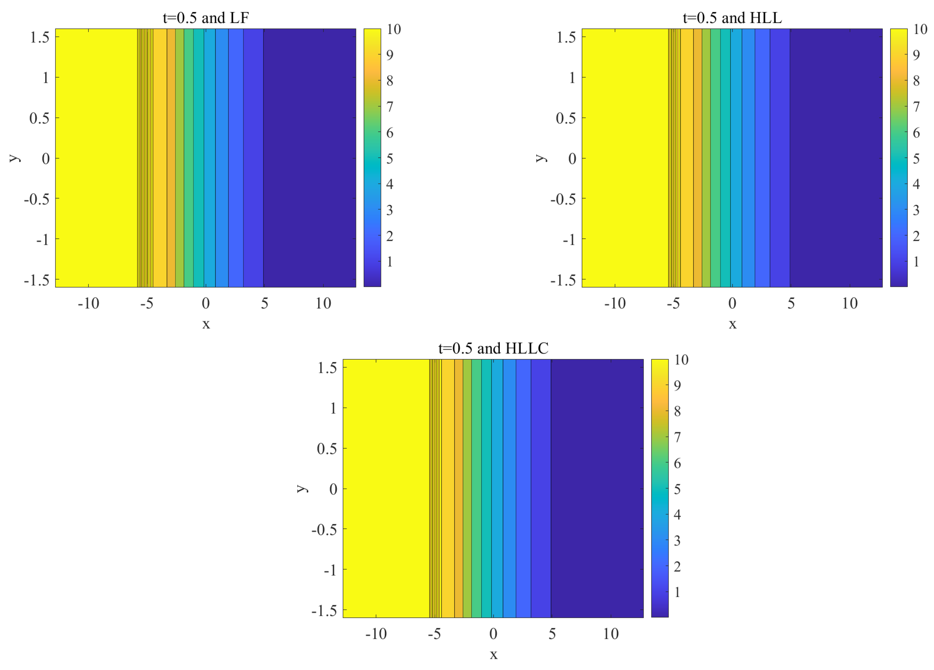
Figure 6 shows the contours of the depth of the granular flow computed by the WENO–LF, WENO–HLL, and WENO–HLLC schemes with 1024 × 128 uniform cells at t = 0.5 , respectively. It can be noted that the numerical results with three different fluxes are identical to each other, that is the contours are straight and no oscillations appear. In order to compare with the exact solution, Figure 7 plots the numerical solutions along y = 0 by the WENO–LF, WENO–HLL, and WENO–HLLC schemes at t = 0.5 . It can be seen that the all three results of the depth are in very good agreement with the exact solution. Similar to the one–dimensional dam break problem, Figure 8 also plots the pointwise absolute errors along y = 0 obtained by the WENO–LF, WENO–HLL, and WENO–HLLC schemes at t = 0.2 , 0.3 , 0.4 , and 0.5 . Similarly, taking a closer look at the error profiles in Figure 8 and Figure 7, we can find that the numerical results computed by the WENO–HLL and WENO–HLLC schemes are still better than those by the WENO–LF scheme, which are identical to the one–dimensional dam break problem.

4.5. Avalanche Flows Slide down an Inclined Plane and Merge Continuously into a Horizontal Plane

In this test problem, we simulated an avalanche of finite granular mass sliding down an inclined plane and merging continuously into a horizontal plane, as shown in Figure 9. This test case is widely used to test numerical schemes for the Savage–Hutter equations such as [15,18].
In order to compare with the results from [15,18], all computational parameters were set the same as they are in the literature. That is, the computational domain is [ 0 , 30 ] × [ 7 , 7 ] and ε = λ = 1 , z b = 0 in our simulations. The inclined section lies x [ 0 , 17.5 ] , and the horizontal region lies in x [ 21.5 , 30 ] with a smooth transition zone in x [ 17.5 , 21.5 ] . The inclination angle is given by
ζ ( x ) = ζ 0 , 0 x 17.5 , ζ 0 1 x 17.5 4 , 17.5 < x < 21.5 , 0 , x 21.5 ,
where ζ 0 = 35 and δ = ϕ = 30 . The granular mass is suddenly released at t = 0 from the hemispherical shell with an initial radius of r 0 = 1.85 in dimensionless length units. The center of the cap is initially located at ( x 0 , y 0 ) = ( 4 , 0 ) .
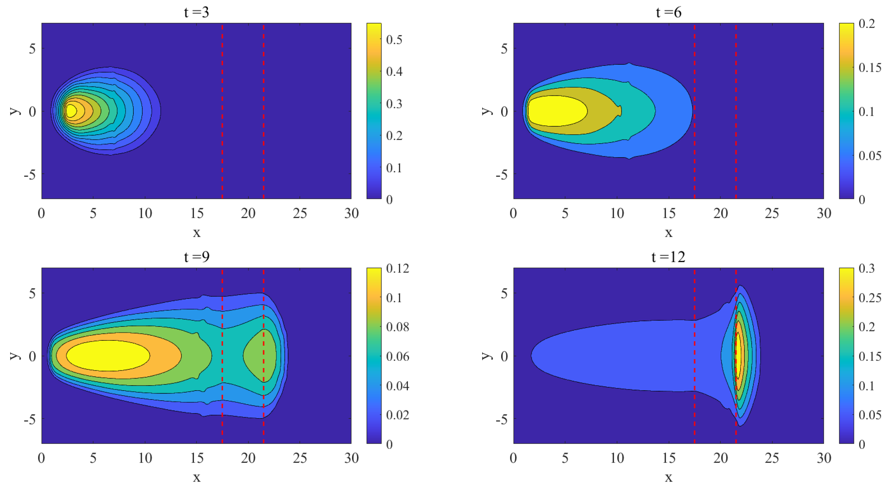
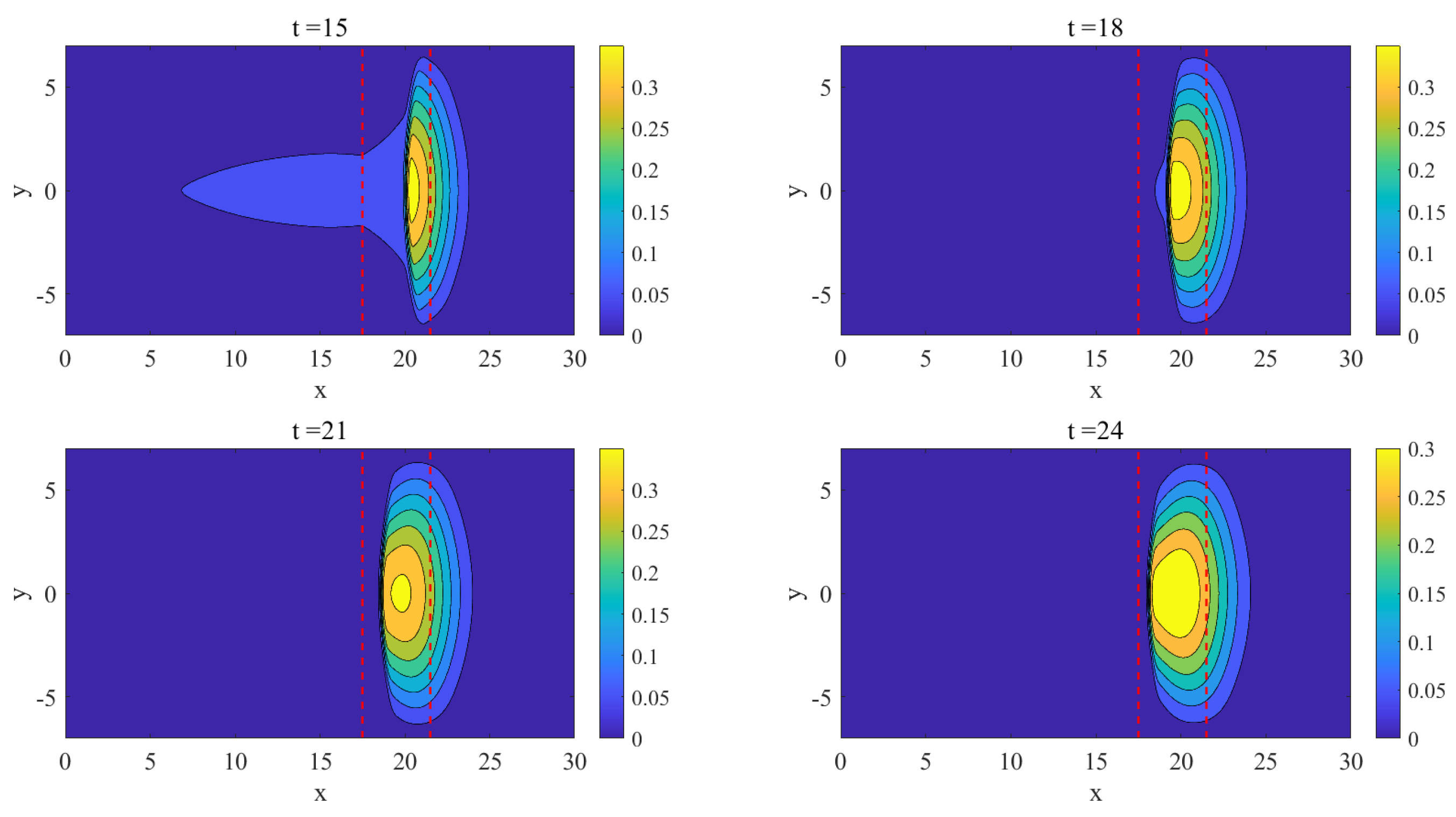
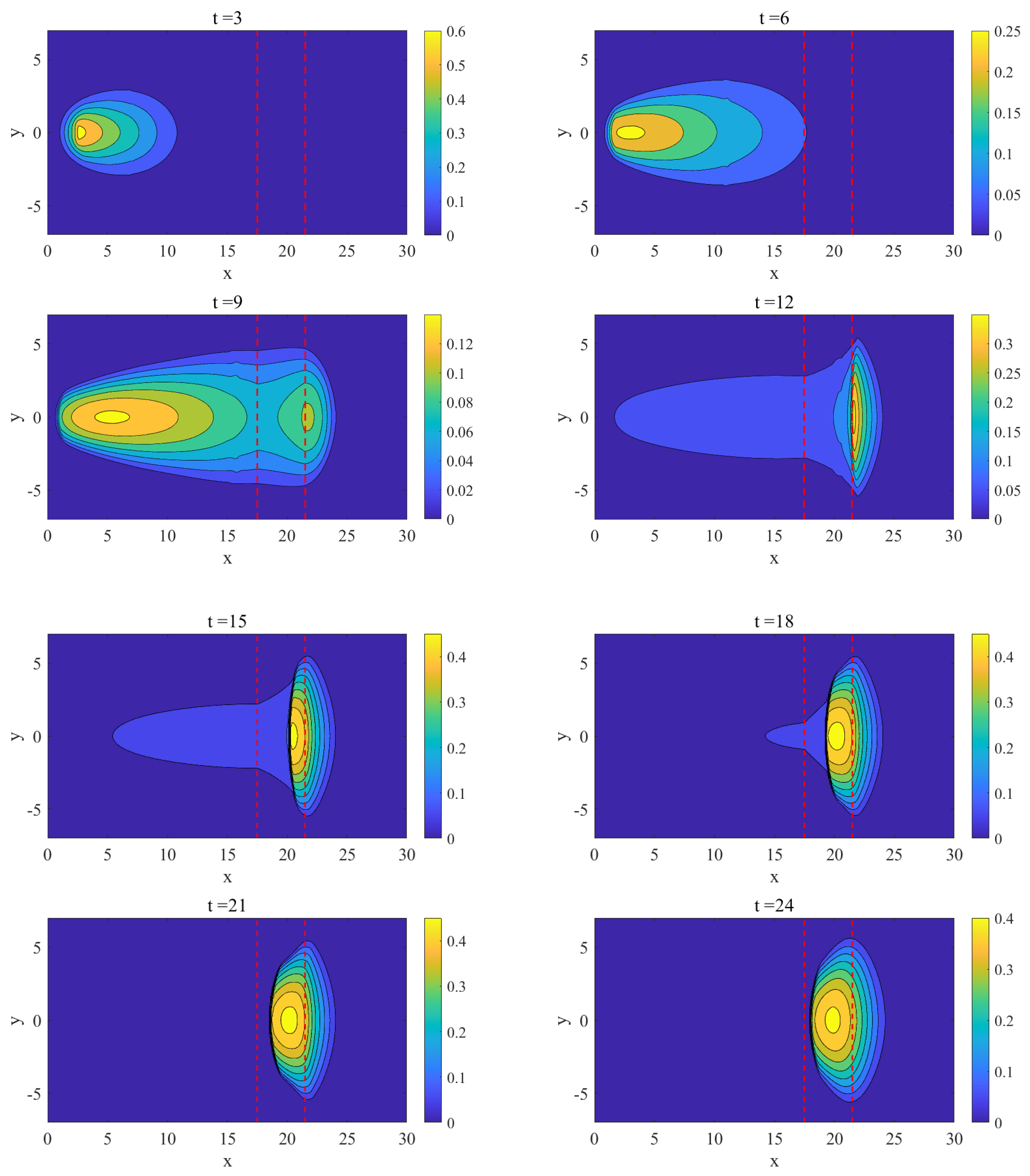
Figure 10, Figure 11 and Figure 12 show the thickness contours of the avalanche body at eight time slices as the granular material slides on the inclined plane into the horizontal run–out zone, obtained with the WENO–LF, WENO–HLL, and WENO–HLLC schemes, respectively. At t = 3 and t = 6 , the granular material slides along the x– and y–directions due to gravity, and it can also be seen that the granular material flows along the downslope direction faster than that of the cross–slope direction. At t = 9 , the front of the avalanche reaches the horizontal run–out zone and begins to deposit since the basal friction force here is sufficiently large, but the tail of the avalanche is still undergoing an acceleration movement. Once the velocity changes from supercritical to subcritical, a shock wave forms around the end of the transition zone at t = 12 . From t = 15 to t = 24 , a backward surge wave can be found within the approaching mass from the tail. At t = 24 , the final deposition of the avalanche is nearly attained. From these figures, we can find that all results are smooth and no oscillations appear. Meanwhile, the results obtained by the three different fluxes are better than those of [15,18]. The WENO scheme with the HLL and HLLC fluxes shows similar numerical results at the eight time slices, and these have some difference from the WENO–LF scheme, especially at t = 21 , 24 , in which a very dissipative behavior for the LF flux appears.

5. Conclusions

In order to develop high–order numerical methods for solving Savage–Hutter equations, which may be discontinuous, we investigated the numerical solution of granular–type flows based on the Savage–Hutter equations using third–order WENO finite volume schemes with the LF, HLL, and HLLC fluxes on structured one– and two–dimensional grids. The numerical results indicate that the WENO finite volume scheme with these fluxes can obtain satisfactory solutions, which can automatically track the discontinuities, and there is almost no numerical oscillation at the discontinuity. In these candidates of numerical fluxes, the WENO–HLLC scheme has the best computational accuracy in all the numerical tests. Although we did not deliberately discuss the computational time in the paper, the cost of WENO–LF is usually the least in most numerical tests, which is estimated to save about 10% of the runtime compared with the WENO–HLL and WENO–HLLC schemes. Thus, if the requirements for computational accuracy are more important, it is recommended to use the HLLC flux, which is also more stable. If the computational accuracy is not high, but the computational time is expected to be as short as possible, it is recommended to use the LF flux.

Author Contributions

Conceptualization, M.W. and X.Z.; methodology, X.Z.; software M.W. and X.Z.; writing and original draft preparation, M.W.; co-review and validation, X.Z.; writing—editing and funding acquisition X.Z. All authors have read and agreed to the published version of the manuscript.

Funding

This research received no external funding.

Institutional Review Board Statement

Not applicable.

Informed Consent Statement

Not applicable.

Data Availability Statement

Not applicable.

Conflicts of Interest

The authors declare no conflict of interest.

References

  1. Savage, S.B.; Hutter, K. The motion of a finite mass of granular material down a rough incline. J. Fluid Mech. 1989, 199, 177–215. [Google Scholar] [CrossRef]
  2. Gray, J.M.; Tai, Y.C.; Noelle, S. Shock waves, dead zones and particle-free regions in rapid granular free-surface flows. J. Fluid Mech. 2003, 491, 161–181. [Google Scholar] [CrossRef] [Green Version]
  3. Hutter, K.; Wang, Y.; Pudasaini, S.P. The Savage–Hutter avalanche model: How far can it be pushed? Philos. Trans. R. Soc. Math. Phys. Eng. Sci. 2005, 363, 1507–1528. [Google Scholar] [CrossRef] [PubMed]
  4. Hutter, K.; Siegel, M.; Savage, S.B.; Nohguchi, Y. Two-dimensional spreading of a granular avalanche down an inclined plane Part I. theory. Acta Mech. 1993, 100, 37–68. [Google Scholar] [CrossRef]
  5. Greve, R.; Koch, T.; Hutter, K. Unconfined flow of granular avalanches along a partly curved surface. I. Theory. Proc. R. Soc. Lond. Ser. Math. Phys. Sci. 1994, 445, 399–413. [Google Scholar]
  6. Gray, J.M.; Wieland, M.; Hutter, K. Gravity-driven free surface flow of granular avalanches over complex basal topography. Proc. R. Soc. Lond. Ser. Math. Phys. Eng. Sci. 1999, 455, 1841–1874. [Google Scholar] [CrossRef]
  7. Paik, J. A high resolution finite volume model for 1D debris flow. J. Hydro-Environ. Res. 2015, 9, 145–155. [Google Scholar] [CrossRef]
  8. Pudasaini, S.P.; Hutter, K. Avalanche Dynamics: Dynamics of Rapid Flows of Dense Granular Avalanches; Springer Science & Business Media: Berlin/Heidelberg, Germany, 2007. [Google Scholar]
  9. Gray, J.M. Granular flow in partially filled slowly rotating drums. J. Fluid Mech. 2001, 441, 1–29. [Google Scholar] [CrossRef] [Green Version]
  10. Iverson, R.M. The physics of debris flows. Rev. Geophys. 1997, 35, 245–296. [Google Scholar] [CrossRef] [Green Version]
  11. Iverson, R.M.; Denlinger, R.P. Flow of variably fluidized granular masses across three-dimensional terrian: 1. Coulomb mixture theory. J. Geophys. Res. Solid Earth 2001, 106, 537–552. [Google Scholar] [CrossRef]
  12. Pitman, E.B.; Long, L.E. A two-fluid model for avalanche and debris flows. Philos. Trans. R. Soc. Math. Phys. Eng. Sci. 2005, 363, 1573–1601. [Google Scholar] [CrossRef]
  13. Koch, T.; Greve, R.; Hutter, K. Unconfined flow of granular avalanches along a partly curved surface. II. Experiments and numerical computations. Proc. R. Soc. Lond. Ser. Math. Phys. Sci. 1994, 445, 415–435. [Google Scholar]
  14. Denlinger, R.P.; Iverson, R.M. Flow of variably fluidized granular masses across three-dimensional terrain: 2. Numerical predictions and experimental tests. J. Geophys. Res. Solid Earth 2001, 106, 553–566. [Google Scholar] [CrossRef]
  15. Wang, Y.; Hutter, K.; Pudasaini, S. The Savage–Hutter theory: A system of partial differential equations for avalanche flows of snow, debris, and mud. Zamm-J. Appl. Math. Mech. FüR Angew. Math. Und Mech. Appl. Math. Mech. 2004, 84, 507–527. [Google Scholar] [CrossRef]
  16. Chiou, M.C.; Wang, Y.; Hutter, K. Influence of obstacles on rapid granular flows. Acta Mech. 2005, 175, 105–122. [Google Scholar] [CrossRef]
  17. Cui, X. Computational and experimental studies of rapid free-surface granular flows around obstacles. Comput. Fluids 2014, 89, 179–190. [Google Scholar] [CrossRef]
  18. Zhai, J.; Yuan, L.; Liu, W.; Zhang, X. Solving the Savage–Hutter equations for granular avalanche flows with a second-order Godunov type method on GPU. Int. J. Numer. Methods Fluids 2015, 77, 381–399. [Google Scholar] [CrossRef]
  19. Vollmöller, P. A shock-capturing wave-propagation method for dry and saturated granular flows. J. Comput. Phys. 2004, 199, 150–174. [Google Scholar] [CrossRef]
  20. Rosatti, G.; Begnudelli, L. Two-dimensional simulation of debris flows over mobile bed: Enhancing the TRENT2D model by using a well-balanced Generalized Roe-type solver. Comput. Fluids 2013, 71, 179–195. [Google Scholar] [CrossRef]
  21. Tai, Y.C.; Noelle, S.; Gray, J.M.N.; Hutter, K. An accurate shock-capturing finite-difference method to solve the Savage–Hutter equations in avalanche dynamics. Ann. Glaciol. 2001, 32, 263–267. [Google Scholar] [CrossRef] [Green Version]
  22. Tai, Y.C.; Noelle, S.; Gray, J.M.; Hutter, K. Shock-capturing and front-tracking methods for granular avalanches. J. Comput. Phys. 2002, 175, 269–301. [Google Scholar] [CrossRef] [Green Version]
  23. Yavari-Ramshe, S.; Ataie-Ashtiani, B.; Sanders, B.F. A robust finite volume model to simulate granular flows. Comput. Geotech. 2015, 66, 96–112. [Google Scholar] [CrossRef]
  24. Lu, C.; Qiu, J.; Wang, R. A numerical study for the performance of the WENO schemes based on different numerical fluxes for the shallow water equations. J. Comput. Math. 2010, 28, 807–825. [Google Scholar] [CrossRef]
  25. Musa, O.; Huang, G.; Wang, M. A New Smoothness Indicator of Adaptive Order Weighted Essentially Non-Oscillatory Scheme for Hyperbolic Conservation Laws. Mathematics 2020, 9, 69. [Google Scholar] [CrossRef]
  26. Shu, C.W. Essentially non-oscillatory and weighted essentially non-oscillatory schemes for hyperbolic conservation laws. In Advanced Numerical Approximation of Nonlinear Hyperbolic Equations; Springer: New York, NY, USA, 1998; pp. 325–432. [Google Scholar]
  27. Shu, C.W. High order weighted essentially nonoscillatory schemes for convection dominated problems. Siam Rev. 2009, 51, 82–126. [Google Scholar] [CrossRef] [Green Version]
  28. Shu, C.W. High-order finite difference and finite volume WENO schemes and discontinuous galerkin methods for CFD. Int. J. Comput. Fluid Dyn. 2003, 17, 107–118. [Google Scholar] [CrossRef]
  29. Dumbser, M.; Käser, M. Arbitrary high order non-oscillatory finite volume schemes on unstructured meshes for linear hyperbolic systems. J. Comput. Phys. 2007, 221, 693–723. [Google Scholar] [CrossRef]
  30. Cooley, K.; Baeder, J. A central compact-reconstruction WENO method for hyperbolic conservation laws. In Proceedings of the AIAA Aerospace Sciences Meeting, Kissimmee, FL, USA, 8–12 January 2018. [Google Scholar] [CrossRef]
  31. Guerrero Fernández, E.; Escalante, C.; Castro Díaz, M.J. Well-Balanced High-Order Discontinuous Galerkin Methods for Systems of Balance Laws. Mathematics 2021, 10, 15. [Google Scholar] [CrossRef]
  32. Li, R.; Zhang, X. A Finite Volume Scheme for Savage–Hutter Equations on Unstructured Grids. Numer. Math. Theory Methods Appl. 2020, 13, 479–496. [Google Scholar]
  33. Toro, E.F. Riemann Solvers and Numerical Methods for Fluid Dynamics, 3rd ed.; Springer: Berlin/Heidelberg, Germany, 2009; pp. 1–749. [Google Scholar]
  34. Toro, E.F. Shock-Capturing Methods for Free-Surface Shallow Flows; Wiley-Blackwell: Hoboken, NJ, USA, 2001. [Google Scholar]
  35. Savage, S.B.; Hutter, K. The dynamics of avalanches of granular materials from initiation to runout. Part I: Analysis. Acta Mech. 1991, 86, 201–223. [Google Scholar] [CrossRef]
  36. Fraccarollo, L.; Capart, H.; Zech, Y. A Godunov method for the computation of erosional shallow water transients. Int. J. Numer. Methods Fluids 2003, 41, 951–976. [Google Scholar] [CrossRef]
  37. Hesthaven, J.S. Numerical Methods for Conservation Laws: From Analysis to Algorithms; SIAM: Philadelphia, PA, USA, 2018. [Google Scholar]
  38. Juez, C.; Murillo, J.; García-Navarro, P. 2D simulation of granular flow over irregular steep slopes using global and local coordinates. J. Comput. Phys. 2013, 255, 166–204. [Google Scholar] [CrossRef]
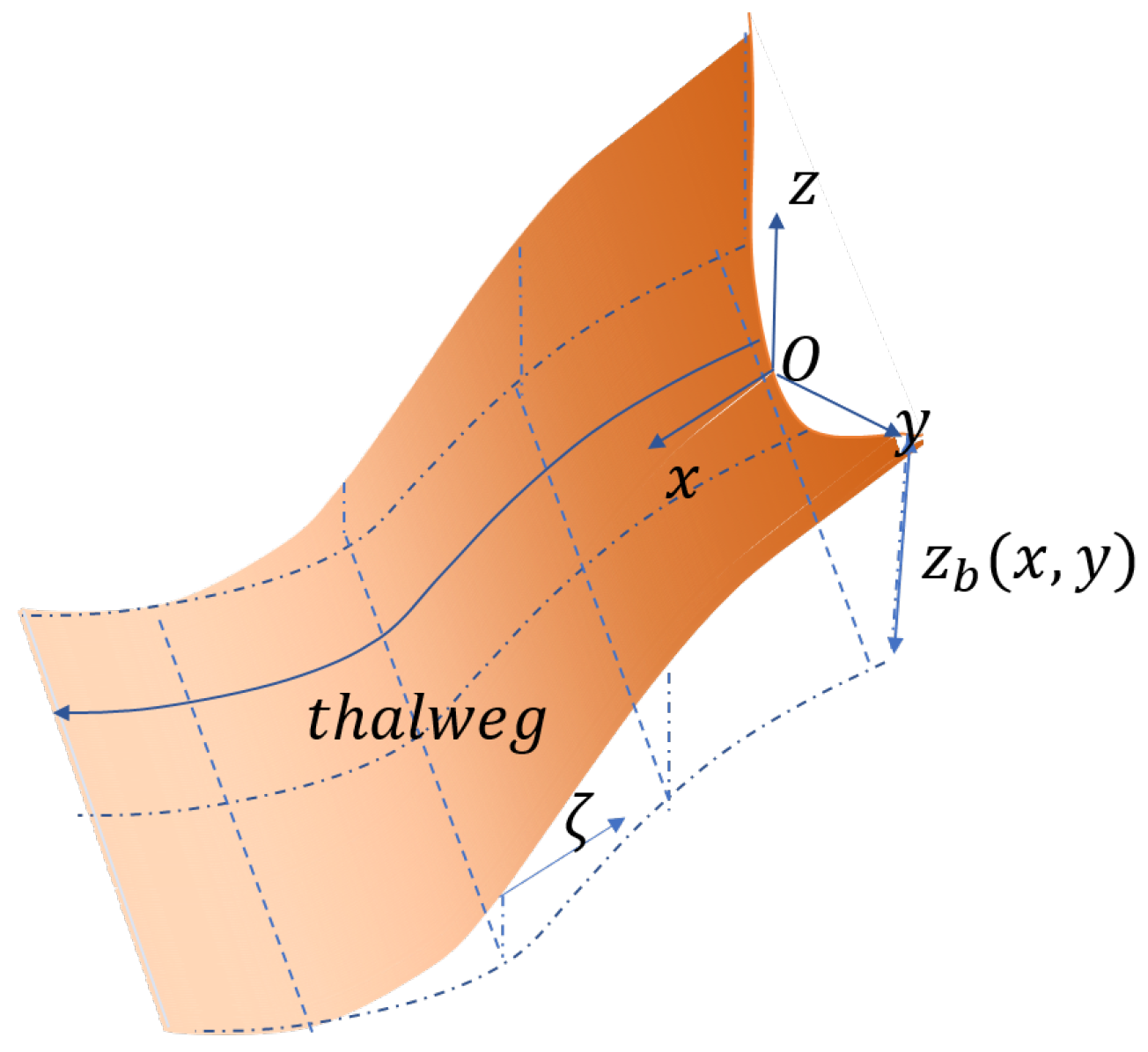
Figure 1. The sketch of curvilinear coordinates for Savage–Hutter model.
Mathematics 10 01482 g001
Figure 2. Depth and corresponding velocity profiles with WENO–LF, WENO–HLL, and WENO–HLLC fluxes at t = 3 , 6 .
Mathematics 10 01482 g002
Figure 3. Depth and corresponding discharge h u profiles with WENO–LF, WENO–HLL, and WENO–HLLC fluxes at t = 2 , 4 , 6 .
Mathematics 10 01482 g003
Figure 4. Analytical solution and numerical solutions with WENO–LF, WENO–HLL, and WENO–HLLC for the 1D dam break problem at t = 0.5 . The solutions of h on the whole domain (left); the solutions of h in the range x [ 4.5 , 3 ] (right).
Mathematics 10 01482 g004
Figure 5. The depth’s pointwise absolute error of numerical solutions with WENO–LF, WENO–HLL, and WENO–HLLC fluxes for the 1D dam break problem at t = 0.2 , 0.3 , 0.4 and 0.5 .
Mathematics 10 01482 g005
Figure 6. Depth contours of numerical solutions with WENO–LF, WENO–HLL, and WENO–HLLC fluxes for the 2D dam break problem at t = 0.5 .
Mathematics 10 01482 g006
Figure 7. Analytical solution and numerical solutions with WENO–LF, WENO–HLL, and WENO–HLLC along y = 0 for the 2D dam break problem at t = 0.5 . The solutions of h on the whole domain (left); the solutions of h on the range x [ 4.5 , 3 ] (right).
Mathematics 10 01482 g007
Figure 8. Pointwise absolute error of numerical solutions with WENO–LF, WENO–HLL, and WENO–HLLC fluxes along y = 0 for the 2D dam break problem at t = 0.2 , 0.3 , 0.4 , and 0.5 .
Mathematics 10 01482 g008
Figure 9. Sketch of the avalanche flow sliding down an inclined plane and merging continuously into a horizontal plane.
Mathematics 10 01482 g009
Figure 10. Thickness contours of the avalanche at t = 3 , 6 , 9 , 12 , 15 , 18 , 21 , 24 for the flow sliding down the inclined plane and merging continuously into a horizontal plane. The transition zone from the inclined plane to the horizontal plane lies between the two red dashed lines. The LF flux is used.
Mathematics 10 01482 g010aMathematics 10 01482 g010b
Figure 11. Thickness contours of the avalanche at t = 3 , 6 , 9 , 12 , 15 , 18 , 21 , 24 for the flow sliding down the inclined plane and merging continuously into a horizontal plane. The transition zone from the inclined plane to the horizontal plane lies between the two red dashed lines. The HLL flux is used.
Mathematics 10 01482 g011
Figure 12. Thickness contours of the avalanche at t = 3 , 6 , 9 , 12 , 15 , 18 , 21 , 24 for the flow sliding down the inclined plane and merging continuously into a horizontal plane. The transition zone from the inclined plane to the horizontal plane lies between the two red dashed lines. The HLLC flux is used.
Mathematics 10 01482 g012
Table 1. L 1 errors and numerical orders of accuracy with WENO–LF, WENO–HLL, and WENO–HLLC fluxes at t = 3 .
NWENO-LFWENO-HLLWENO-HLLC
L 1 ErrorOrder L 1 ErrorOrder L 1 ErrorOrder
180 2.6 × 10 3 - 9.3081 × 10 4 - 9.5808 × 10 4 -
360 3.5667 × 10 4 2.8658 1.1933 × 10 4 2.9635 1.1684 × 10 4 3.0356
720 4.5205 × 10 5 2.98 1.5457 × 10 5 2.9486 1.4077 × 10 5 3.0531
Publisher’s Note: MDPI stays neutral with regard to jurisdictional claims in published maps and institutional affiliations.