1. Introduction
Mechanical assemblies are used widely in the daily lives of modern people. For example, in the morning, there are numerous examples of these essential devices, such as analog alarm clocks that ring to wake us up, doorknobs that we turn to get out of their rooms after waking up from bed, grinders that grind coffee beans for our morning coffee, and cars that we drive to work. These mechanical assemblies have been traditionally designed by a few experts and manufactured on large scale in factories to satisfy universal objectives. Nowadays, people can directly fabricate devices that meet their own objectives through the maker movement and the general spread of 3D printers [
1]. With this trend, even elementary school students can receive integrated science, technology, engineering, and mathematics (STEM) classes or after-school classes, which include practical training based on 3D printers [
2]. However, it is difficult to intuitively identify a relationship between specific mechanical movements and mechanical structures that facilitate such a movement. Therefore, mechanical assembly design, which is the first stage of individually customized fabrication, can serve as a barrier that disrupts the access of non-experts who have not studied mechanical engineering. For example, when ordinary people are provided with a sufficient number of parts that can be used for assemblies, such as gears, cams, and connecting rods, and asked to design a mechanical structure for moving the location of a beverage cup based on these parts, most of them could give up soon.
In the field of computer science, research has been actively conducted to develop methods that can derive efficient design plans by applying computer algorithms [
3]. The so-called computational design methods mainly apply optimization algorithms to automatically identify an optimal design plan, which can satisfy objectives and constraints that are mostly established by the user, among all the design plans available. As these methods completely authorize computers to perform design works, which depend on the knowledge-intensive labor of experts, they can reduce the costs required for design works, such as the time and effort. These solutions can also derive efficient and stable design plans that are beyond the limitations of human experts in terms of their experience, knowledge, and imagination. However, the optimization-based design tools have the following problems. First, the successful application of optimization algorithms requires a specifically restricted range of targets that can be designed to maintain the appropriate size of the design space. Consequently, these tools are likely to be specialized for certain objectives. Second, the users of these tools should express desired design objectives based on a series of numerical objectives and constraints, which are equivalent to input data for optimization algorithms. Users can find it difficult to convert design objectives to clear mathematical expressions. They can also encounter difficulty in identifying and correcting problematic parts when they receive undesired results caused by errors in defining incorrect objectives or omitting certain constraints.
This study proposed an interactive system that can enable general users to assemble devices and immediately inspect movements of the assembled devices through direct manipulation and physics-based simulation in a virtual reality (VR) environment. The proposed system can also support users to evaluate the design space easily and identify the target mechanical structure swiftly using an exploratory interface applying a genetic algorithm. Because this system allows users to assemble mechanical parts provided in arbitrary ways, they are free from restraints on the range of designable mechanical assemblies and can use this system as a universal design tool. Moreover, this system uses algorithms to explore design plans and enables users to perform evaluations. In this regard, this system shows an essential difference from optimization-based design tools, which order computers to solely perform exploration and evaluation of design plans. In other words, the proposed system helps users intuitively explore the design space through repeated interaction and obtain a design plan that can satisfy the desired objectives and constraints without presenting design objectives and constraints in a standardized format that a computer can understand.
The proposed system was developed mainly based on the undirected graph structure, which is the genetic encoding of mechanical assemblies. The nodes and edges of this graph indicate mechanical parts and a coupling relationship between these parts, respectively. When users add a new part, remove existing parts, or connect two different parts using a motion controller, an input device in the VR environment, corresponding nodes or edges are generated or eliminated. Through this process, the inner graph structure is renewed. Several mechanical assemblies can exist simultaneously in the VR space, and each assembly is represented as its unique, independent graph gene. Users select two different mechanical assemblies and command a crossover of these assemblies to explore new design plans that combine the characteristics of these assemblies. Specifically, the crossover process splits corresponding graphs to both assemblies into two subgraphs, respectively, and exchanges these subgraphs to generate new graph genes, and ultimately creates a corresponding mechanical assembly to the graph gene in the virtual space. When users command the crossover process, the proposed system repeatedly performs crossover operations on the same two graph genes to generate a number of different next-generation genes and regularly place corresponding mechanical assemblies to these genes like galleries in the virtual space. Users can virtually inspect the structure and movement of new mechanical assemblies, save assemblies that satisfy objectives, and remove the other assemblies. Users can also repeat the crossover process on the remaining assemblies to constantly explore the design space in the desired direction.
Furthermore, this study conducted an experiment based on users, which can be quantitatively evaluated, and analyzed the experimental result to verify the effectiveness of the proposed interactive system. Specifically, non-experts were provided with a project on ‘mechanical assembly design that can represent the straight reciprocating motion’, for which they cannot easily provide a solution. They were then asked to derive the optimal design plan for the project within a limited time. The experimental result showed that users showed significantly higher values of objective achievement indices when they used both the direct manipulation interface and the crossover operation interface than when they used only the direct manipulation interface. Based on this experimental result, this study concluded that the proposed evolutionary exploration interface exhibits significantly effective performance for enabling non-experts to perform mechanical assembly design tasks. Additionally, it is expected that everyone can easily fabricate their own customized mechanical assembly using the proposed interface combined with a customized fabrication system.
The key contribution of this paper is that a novel approach to interactive mechanical design is presented for allowing the user to evolutionarily explore design spaces in immersive virtual reality systems. The genetic algorithm has long been adopted to a large diversity of interactive design systems due to its effectiveness in coping with large-scale design spaces primarily based on its crossover operation. The presented evolutionary algorithm based on our dedicated crossover operation facilitates the discovery of new and insightful possibilities of recombining given mechanical designs while preserving the existing substructures which are highly probable to contribute to their original mechanical movements. Furthermore, on top of the evolutionary algorithm, the presented direct manipulation interface maximizes the power of interactive exploration in design spaces by translating conceptual design possibilities into nearly tangible ones in virtual reality, which the user can visually examine and directly manipulate by moving his/her own heads and hands in the immersive 3D space.
The remainder of this paper is organized as follows. The previous research efforts related with this paper are classified into three categories and briefly introduced in
Section 2. How the mechanical assemblies are represented and simulated in our system is described in
Section 3. The direct manipulation interface for assembling mechanical structures is clarified with precise mathematical equations in
Section 4. As the core of our system, the crossover operation algorithm tailored to the representation of mechanical assemblies and the VR interface for evolutionary exploration is explained in detail in
Section 5. The setup and results of our user study for demonstrating the effectiveness of our approach are presented and analyzed in
Section 6. Lastly, the contributions, limitations, and future research directions of this paper are summarized in
Section 7.
2. Related Work
Research has been constantly conducted for a long time to develop VR systems for effectively designing and fabricating mechanical assemblies [
4]. Because these systems require a process of elaborately assembling several parts in a VR environment, they should be provided with an interface that supports precise manipulation in a three-dimensional space [
5]. The direct manipulation interface allows users to move or rotate virtual objects by holding them with their hands in a similar way to that in the real world [
6]. Therefore, this interface has been widely applied in numerous VR systems. The mechanical assembly system proposed in this study also allows users to move or rotate mechanical assemblies by directly holding them with their hands in virtual space based on motion controllers that they hold in the real world. They can also connect two different parts by holding them with both hands. As such, a method that matches manipulation in the real world with manipulation in the virtual world, facilitates intuitive and natural interaction. Furthermore, researchers have conducted research on manipulating targets in random sizes more easily and accurately using a degree of freedom, which can be additionally obtained only in VR. For example, researchers have developed various methods that enable users to manipulate a target located far from them by casting a virtual ray that stretches infinitely from their hands [
7], easily approach a random target by reducing the extensive virtual world to a miniature size that can be manipulated by their hands [
8], or precisely control targets to be manipulated using auxiliary virtual mirrors that are used to identify a spatial relationship among these targets [
9]. This study proposed an interface that enables users to intuitively explore a design space, a set of possibilities that can be obtained through a combination of each object beyond the existing interface that supports the convenient manipulation of each object. The proposed interface allows users to effectively fabricate new mechanical assemblies containing the structure and motions desired by users.
An interactive exploration of the design space, which can be created through the adjustment or combination of previously given basic elements, is an approach method that has been effectively used to synthesize or edit images, shapes, and animations in the field of human–computer interaction (HCI) [
10]. Secretan et al. reported that a number of users generated various types of interesting images by cooperatively evolving images in the online space based on the NeuroEvolution of Augmenting Topologies (NEAT) algorithm [
11,
12]. Fisher et al. developed a method, which can synthesize and display scenes that can be derived based on input scenes using similar scenes included in a database to examples of placement of three-dimensional (3D) objects that users suggested as input scenes [
13]. Desai et al. obtained a database, which connected a parameter for controlling robots and the significance of a motion derived by the parameter and used this database to help users explore desired robot motions in a semantic space [
14]. Swearngin et al. developed a method that converted the design requirements of the upper level demanded by users to specific constraints of the lower level to present several user interface layout candidates that satisfied such constraints [
15]. Averkiou et al. performed hierarchical embedding of 3D models comprising combined basic elements in a low dimensional space and allowed users to explore the embedded space to effectively synthesize a new 3D model [
16]. Zheng et al. presented an efficient algorithm for identifying the functional substructure of a 3D model and used this algorithm to replace parts that can be exchanged between two models [
17]. They reported that this new model synthesis process derived a plausible outcome maintaining the functional properties of the target models. Xu et al. defined a new crossover operation that can increase the variety of a 3D model in an evolutionary process in a similar way to the proposed method in this study [
18]. They also used this operation to help users explore the design space based on interactive evolution and become inspired for creative design. This study proposed the optimized genetic encoding method and crossover operation for a specific design domain of mechanical assemblies instead of general 3D models. The proposed methods enable users to select, exclude, re-assemble, and simulate mechanical assemblies through direct interaction and explore design spaces for mechanical assemblies easily and intuitively.
Evolutionary approach methods such as the genetic algorithm have been successfully applied for a long time to design mechanical assemblies and robots, which require a massive size of space for exploration [
19,
20]. Karl Sims published a pioneering research paper in 1994, which stated that genetic algorithms can be used to successfully evolve the structure and behavioral patterns of artificial life [
21]. Funes and Pollack developed a method for evolving a Lego structure in a physically stable range to apply simulated results in a virtual environment to the real world [
22]. They also verified that the developed method allowed users to assemble evolved results by practically using Lego bricks. Park and Lee effectively optimized the structure and behavioral patterns of modular robots by alternatively applying a genetic algorithm and a reinforcement learning algorithm [
23]. In the field of genetic algorithm, the presented approach can be regarded as a kind of interactive genetic algorithm, in which the system only handles the process of reproduction, such as crossover, and the users themselves evaluate the fitness of each entity and select the parents to be reproduced based on those subjective fitness evaluations [
24]. Interactive genetic algorithm has been successfully employed in a large variety of design problems such as UI design [
25] and fashion design [
26]. This study applied the undirected graph data structure as a genetic encoding method for evolving mechanical assemblies. It is known that genetic encoding based on an undirected graph can also be effectively used in other fields related to the design of electronic circuits, molecular structure [
27], or sensor networks [
28]. The application range of evolutionary algorithms has been broadened consistently so that they can handle a large variety of significantly different problems, including feedforward multi-layer perceptron training [
29], large-scale biomedical ontology matching [
30], clustered shortest-path tree finding [
31], and vehicle routing with backhauls [
32], just to name a few examples.
3. Virtual Mechanical Assemblies
This chapter presents elements used to represent virtual mechanical assemblies. Specifically, it describes the components of parts, which serve as essential elements composing a mechanical assembly, a method of constructing a mechanical assembly by connecting parts, and a process of power spread.
3.1. Properties of Parts
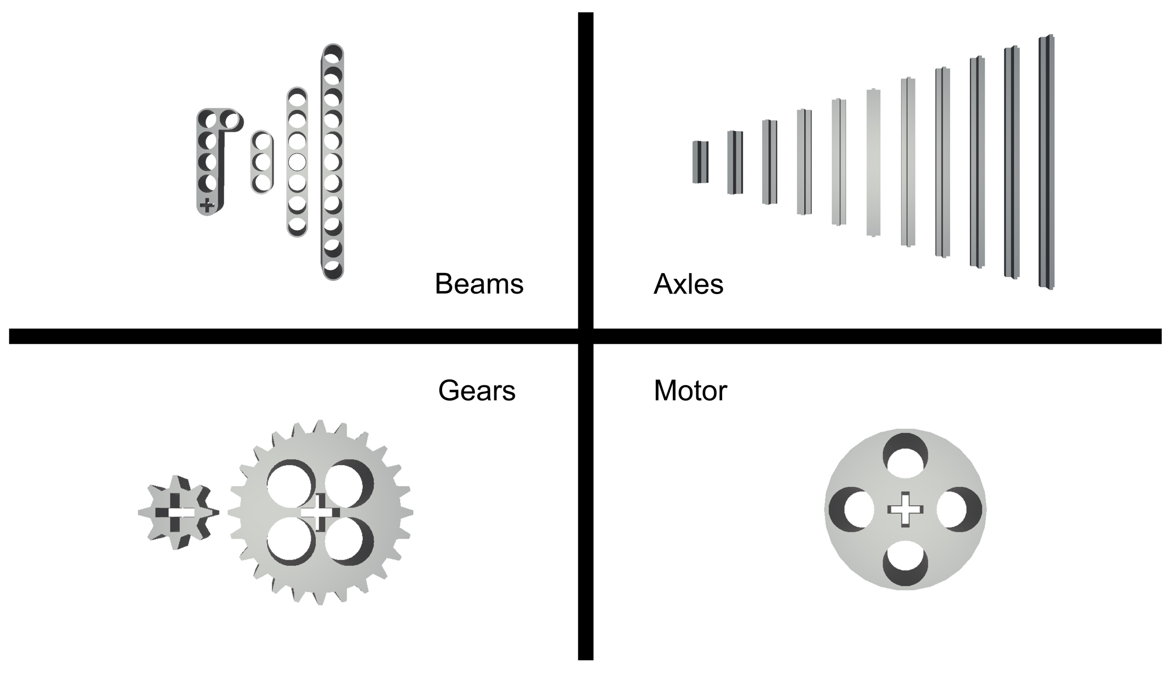
Parts used to fit a mechanical assembly should deliver power easily and be assembled intuitively. In this regard, this study adopted certain parts of the Lego Technique series, which satisfied the aforementioned requirements of parts (see
Figure 1). This study formed 3D meshes by imitating each part, identified the necessary elements for assembly and operation based on the 3D meshes, and generated data of the identified elements, which were defined as property data. Property data included and stored the following elements: names of parts, types of parts, types of parts or connecting sections which can be connected, rotational properties of parts, unique data of each part (e.g., the number of gear teeth), location of connecting sections such as holes, and types of parts that can be connected to connecting sections.
3.2. Part Representation
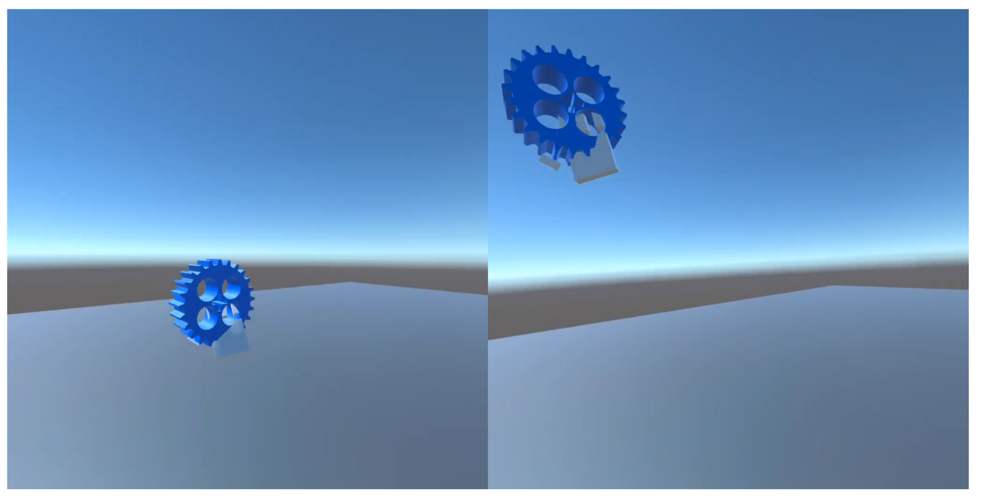
The processes of representing each part in the VR space are as follows. Data are classified as property data for storing the properties of parts and mesh data for determining the 3D form of objects. The proposed interface integrates mesh and property data and represents the integrated result in the VR space to facilitate the successful operation of functions for part connection and power delivery. Users can visually inspect the list of parts that can be generated based on the part generation UI. When they select parts to be generated and move their controllers to the desired parts, 3D parts applying the property data are displayed.
3.3. Properties of Assemblies
It is required to represent data of parts composing a mechanical assembly and connection relations in the process of assembling, storing, or applying a mechanical assembly. When users select random parts, the proposed interface stores data of the selected parts, such as the location and rotation of each part and connects the relations of these parts. Here, the data of the location and rotation of parts are converted to those of the relative coordinates and rotation based on the starting parts to facilitate the convenient representation of these parts in the virtual space.
Users can use controllers to save or load mechanical assemblies that they fabricated. The size of the mechanical assemblies to be loaded should be reduced to avoid collision between the assemblies and allow users to inspect them at a glance. When users determine the mechanical assemblies to be loaded and put buttons using their controllers, the developed interface represents the selected assemblies in the original size in VR space and removes the list of the remaining mechanical assemblies.
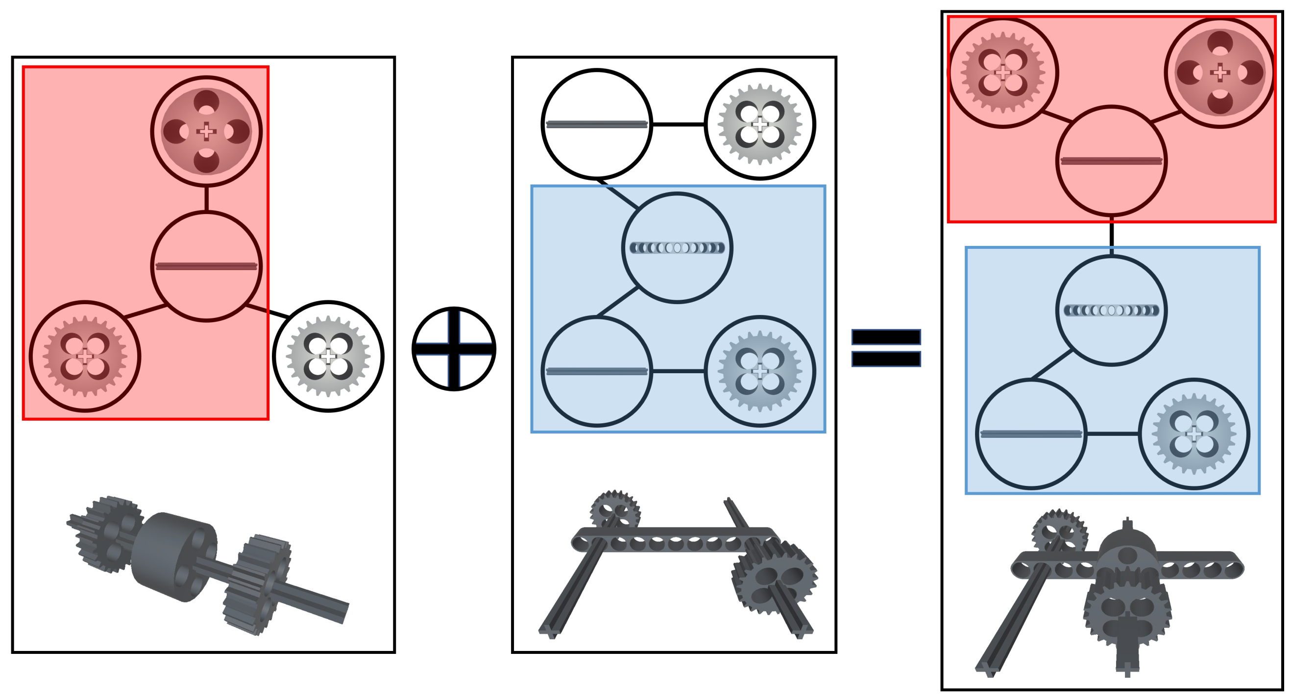
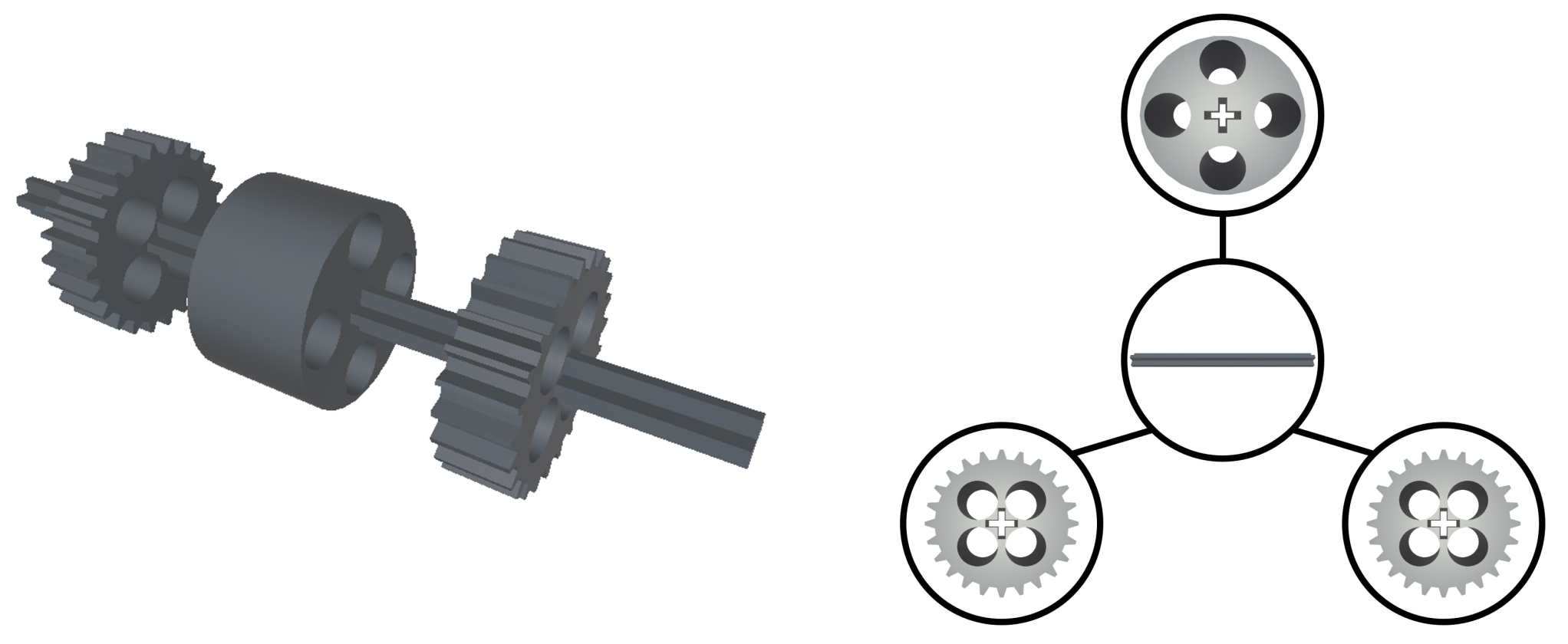
3.4. Graph-Based Representation of Assemblies
This study represented the structure of the connection between parts as that of an undirected graph to help users identify the entire structure of the parts connected (see
Figure 2). Parts composing a mechanical assembly are nodes of the graph and connecting contact sections with other parts are edges of the graph. The graph structure can be used to define the connecting structures, inspect, move, or rotate the entire parts connected, or perform power simulations. The properties of the nodes include locational information, rotational information, the list of edges possessed by nodes, types of parts, and names of parts. The properties of the edges include parts to which they belong, types of edges that can be connected, edges connected, and types of rotation (see
Table 1). Each node can approach other nodes based on the edges that they possess and other edges connected to their edges. Users can identify the connected nodes using the properties of the nodes and edges and recursively repeat the aforementioned processes to identify the entire structure of the mechanical assembly.
T is a rotation type serving as an element used in power simulation. , a rotation type of an edge delivering power and an edge receiving it, is compared with , a rotation type currently spreading, to determine the rotation type to be transferred. Rotation types are prioritized to facilitate convenient control. A rotation type with high priority is applied to nodes that received power and all the nodes connected. A rotation type with low priority is applied to only nodes that received power. When is determined as a rotation type with high priority, it is not replaced. When has a higher priority than , is replaced with . When both and have a low priority, is not replaced.
Power rotation types include a case (tight rotation) in which nodes perfectly combined with connecting sections rotate based on the rotation axis with a local coordinate system rotating; a case (loose rotation) in which nodes loosely combined with connecting sections rotate based on the rotation axis with a local coordinate system not rotating; a case (stop rotation) in which rotation should be suspended; and a case (gear rotation) in which rotation between gears is performed. Tight rotation and gear rotation are rotation types with low priority, whereas loose rotation and stop rotation are rotation types with high priority. In the cases of tight rotation and gear rotation, nodes rotate based on the rotation axis and their location. In the case of loose rotation, only the first node applying loose rotation rotates to enable the nodes connect to follow the motion of the first node rotating. Subsequently, nodes that delivered loose rotation stop rotating. Breadth first search is implemented to identify nodes that were connected to nodes to be rotated but not explored yet. Then, the nodes connected to nodes to be rotated are moved. Stop rotation is delivered to the connected nodes to omit rotation.
3.5. Power Simulation
This system implemented a simulation sub-system that allows power generated from a motor to spread through connected parts along with the graph representation defined above (see Algorithm 1). This system induces power to move around the part graph, deliver rotational information to each node, and support appropriate motion of parts.
Each node sequentially delivers power to the connected nodes based on edges to represent the motions of the mechanical assembly. To deliver power, a node (
n) in a graph receives information on the rotation axis (
a), central location (
p) of rotation, rotation velocity (
s), a rotation type (
T), and the list (
S) of nodes were previously explored from the previous node. Users can manipulate the motor to turn on or off the power supply, and the power delivery system is operated when the motor rotates. When a power supply is executed, depth first exploration is applied to the graph structure from the motor to recursively deliver power. If a cycle exists, power is delivered to only nodes that are not included in the list of nodes explored, which was delivered by the previous node, to avoid a re-visit to the previously explored nodes.
| Algorithm 1 Power Transfer |
| function PowerTransfer(a, p, s, T, S) ▹ Where S : Array |
| if S not contains n then ▹ Where n : node(brick) |
| S.push(n) |
| Rotate n by T |
| for in edges of ndo ▹ Where edges : Array |
| if is high priority or both T and is low priority then |
| change a, p, T to , , |
| end if |
| for in connected edges with do |
| if is high priority or both T and is low priority then |
| change a, p, T to , , |
| end if |
| .PowerTransfer(a, p, s, T, S) ▹ : node of |
| end for |
| end for |
| end if |
| end function |
4. Direct Manipulation Interface
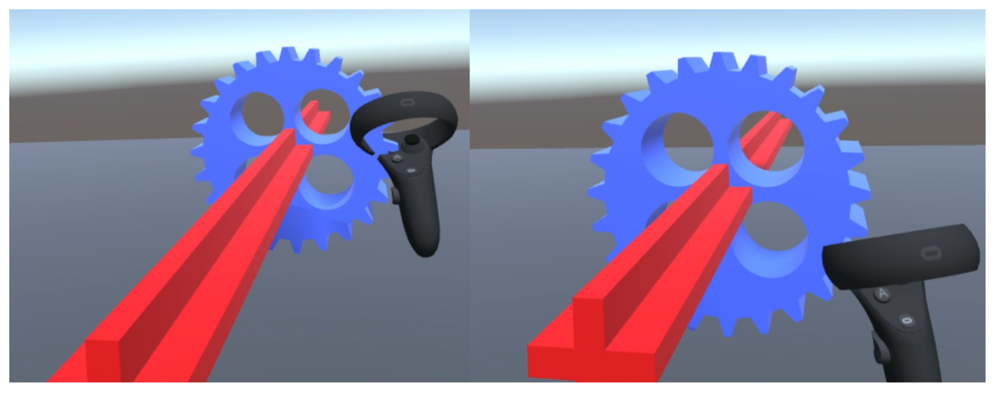
This study presented users with an environment where they were allowed to fabricate and assemble parts. Users interact with the environment provided using VR controllers, and the location and rotation of controllers in the real world are reflected in the virtual space. VR controllers enable users to display or hide the part generation UI, rotate the motor in a clockwise or counterclockwise direction, and move or rotate parts. When controllers reach parts, the contacted parts are selected. When controllers move apart from the selected parts, the selection state is terminated. Users should identify both parts selected based on connection relations and parts connected to the selected parts to control all the parts. The selected parts are controlled according to buttons pushed by users. Part control consists of part movement and part rotation. When parts are connected, the proposed interface calibrates the location of the connected parts or restricts a direction of movement to ensure user convenience for manipulation. Details of the manipulation are as follows.
4.1. Part Translation
When parts are not connected, users can move these parts freely (see
Figure 3). To provide users with a feeling of directly moving objects, the original location (
p) of a part is added with change (
) in the location of the controller to identify the adjusted location (
) of the part the change in the location of the controller is calculated based on the location of the current frame and previous frame. When the entire part is moved, the aforementioned method is applied to calculate the change in the location of the selected part. Then, all the parts connected are moved according to changes in the location of the selected part calculated.
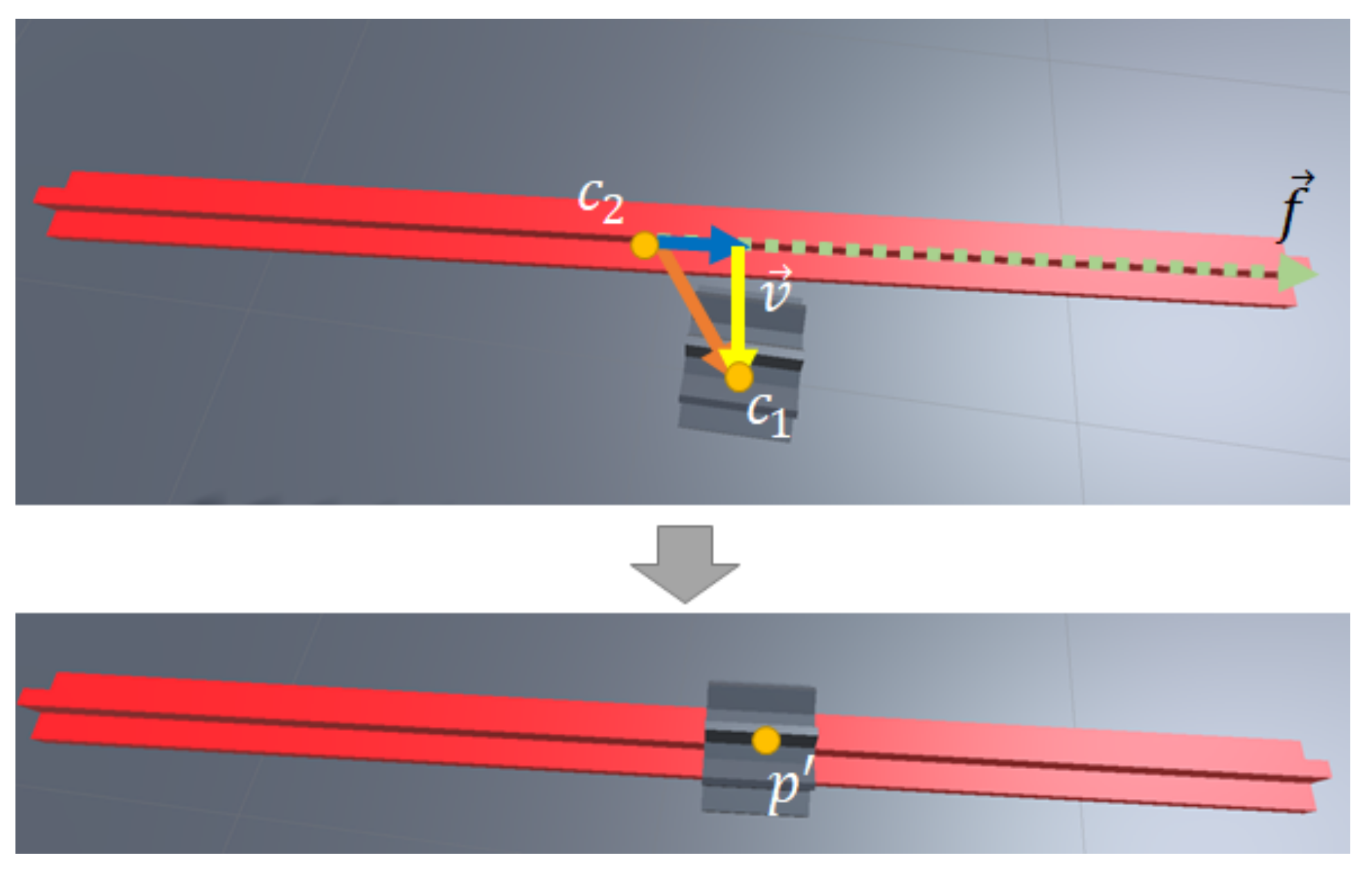
When parts are connected, they are moved along with the connecting sections (see
Figure 4). Change in the location of the controller is projected in the vector (
) of parts in the movement direction making parts move in a straight direction. Here, the vector of parts in the movement direction is established to make parts pass through holes in connecting sections.
4.2. Part Rotation
In the process of part rotation, the proposed interface generates a virtual circle that has the same location and center as those of the selected part (see
Figure 5). The selected part is established as a sub-object for the circle. The radius of the circle was established as the distance from the center of the part and controller. The circle was rotated according to a change in the location of the controller to intuitively rotate the object. The rotation axis (
) of the part is a vertical vector to vectors heading for location (
) of the controller based on the previous frame from the center of the circle and location (
) of the controller based on the current frame from the center of the circle. The rotation angle (
) is an included angle between two vectors.
4.3. Calibration of Location
When parts are combined, they are moved to locate these parts at holes on connecting sections (see
Figure 6). The central location (
) of the currently manipulated part is subtracted from the central location (
) of the connecting section to calculate the vector (
) of the distance difference. This vector is projected to the vector (
) of the currently manipulated part in the movement direction. The projected vector is subtracted from
to derive a vector that can calibrate the location of the part in a vertical direction to
. The calibration vector is subtracted from the original location (
p) of the part.
5. Evolutionary Exploration Interface
This study assumed that target users were inexperienced in managing mechanical mechanisms. As they cannot predict the motions of mechanical assemblies easily, they might find it difficult to finish designing appropriate assembly structures for desired objectives. This study proposed a crossover operation interface for these users.
A crossover operation is basically a part of a genetic algorithm, which is used to evaluate behaviors or properties of a target to be optimized and adjust the composition of the target based on the evaluation result. Generally, this algorithm places several comparison targets, selects targets that gained the most excellent evaluation results, and generates new comparison targets by referring to components of the selected targets. Fitness refers to the value of a property serving as an evaluation standard, and the crossover operation is a technique for generating new elements based on the existing elements. The genetic algorithm repeats the crossover operation multiple times to derive the optimized result that can perform or represent the objective the most successfully.
This study provided users with the authority to establish fitness, repeat the crossover operation in each generation, and ultimately identify the optimal structure instead of automating these processes. Such authority allows users to visually inspect the motions of mechanical assemblies, determine more excellent mechanical assemblies, and fabricate new mechanical assemblies based on existing mechanical assemblies through crossover operations. This study conducted experiments to verify whether users can design appropriate mechanical assembly structures in the aforementioned environment.
5.1. Crossover Operation Algorithm
The crossover operation algorithm is based on the part graph structure. In the graph structure (
G), two nodes that are not duplicated are selected randomly. The selected nodes and connected to the selected nodes are alternatively inspected to group them. Through this process, the part graph is classified as subgraphs
and
with the connecting structure of the nodes maintained. The connecting relation between both subgraphs is also maintained. These processes are also applied to another graph structure (
) to derive four subgraphs
,
,
, and
. The subgraphs obtained are used to generate a new assembly graph
or
(see
Figure 7). To form a new assembly graph, a node is randomly selected in two subgraphs, respectively. It is then inspected whether certain edges of the selected nodes can be connected. If these edges exist, the edges of both nodes are logically connected. Subsequently, the location of the subgraph
are adjusted according to the location of the edge of the subgraph
previously connected in the process of practical part rendering. Detailed processes are as follows (see Algorithm 2). Users order a crossover command based on the crossover operation interface. Based on this order, two nodes,
and
, are randomly selected to divide a graph into two subgraphs. Then, two queues,
and
, are generated, and
and
are placed in these queues. The nodes placed in queues are pulled out and stored in a sequence. Subsequently, nodes connected to the aforementioned nodes are placed in queues. These processes are applied to both queues and repeated until all the nodes are explored. Consequently, a graph can be classified as two sequences.
The computation indicated in Algorithm 2 is applied to two graph structures,
G and
, and a subgraph is brought from each graph. A node is then randomly selected in each subgraph. The types of edges that can be connected among all the edges of both nodes are analyzed to select a pair of edges that can be combined and can connect these edges. If these edges are not connected, a node is randomly selected again in each subgraph, and the processes described above are repeated. If edges are not connected despite the exploration of all the parts, a subgraph is randomly re-generated in a parent graph, and the aforementioned processes are repeated.
| Algorithm 2 Seperation |
| function Seperation(G) ▹ Where G : Array |
| Output : ▹ Where , : Array |
| if then |
| |
| |
| else |
| random from 1 to size] |
| random from 1 to size] ▹ |
| |
| ▹ Where , : queue |
| while not visitting every node in G do |
| for node n in except added in this iteration do |
| if is false then |
| = true |
| .add(n) |
| .push(n.nextNode but not searched) |
| end if |
| end for |
| for node n in except added in this iteration do |
| if is false then |
| = true |
| .add(n) |
| .push(n.nextNode but not searched) |
| end if |
| end for |
| end while |
| end if |
| end function |
5.2. Crossover Operation Interface
The proposed interface applied the crossover operation, which is a part of the genetic algorithm. Because users were provided with this interface, they participated in the optimization process, unlike general genetic algorithm processes. The proposed interface partially copies and integrates mechanical assemblies fit by users to present a new mechanical assembly.
Users need two mechanical assembly structures to use the crossover operation algorithm in a VR environment. Additionally, they are provided with two-parent setting interfaces for crossover operation, which are used to register mechanical assembly structures as parent devices for crossover operation in a VR environment, crossover operation interface for executing crossover operations, and 14 result interfaces for displaying the crossover operation results (see
Figure 8).
When each part of mechanical assembly structures reaches the parent setting interfaces, these interfaces load and save all the graph structures from these parts and enter into a crossover standby state. When both parent setting interfaces are in a crossover standby state and users move controllers toward the crossover operation interface, the crossover operation algorithm is operated to display the crossover result of the two mechanical assembly structures on result interfaces. A subgraph is moved and rotated to make two subgraphs look connected naturally. When users select one of the crossover operation results, the other results are eliminated. Users can use crossover operation results for their crossover operation.
6. Experimental Results
6.1. Environment
Unity, a game production engine, was used to establish an experimental environment, and Oculus Quest 2 was used as a VR device, which was capable of running as a standalone headset so that the participants in our experiments were able to move freely without physical constraints imposed by connecting cables. Launching the VR application for experiments, equipped with the headset, participants were immersed in a 3D environment in which only a large floor plane was placed under the feet. Each participant was asked to assemble a mechanical structure that satisfied specific requirements from the scratch using the direct manipulation only or additionally with the evolutionary interface. The direct manipulation interface allowed the instantiation of new mechanical parts, translation and rotation of existing parts, and connection between any two existing parts. With the evolutionary interface, users first placed two existing mechanical structures to parent setting areas, which were visually represented as translucent cubes floating in the air, and then pressed the execution button next to the parent setting areas, which generated 14 new mechanical structures corresponding to the children of the given mechanical structures. Participants were given the options to keep any of those child structures if they satisfied the given requirements more precisely than existing mechanical structures, or to simply discard ones otherwise. Each experiment was allowed to end when a participant determined that he/she had completed the given task, or was forcibly terminated if the time limit was exceeded. The mechanical structures at the end of the experiments were automatically saved and, thereafter, were evaluated according to the measurement criteria. Please refer to the
Supplementary Materials if you would like to visually examine the experimental environments in detail.
6.2. Method
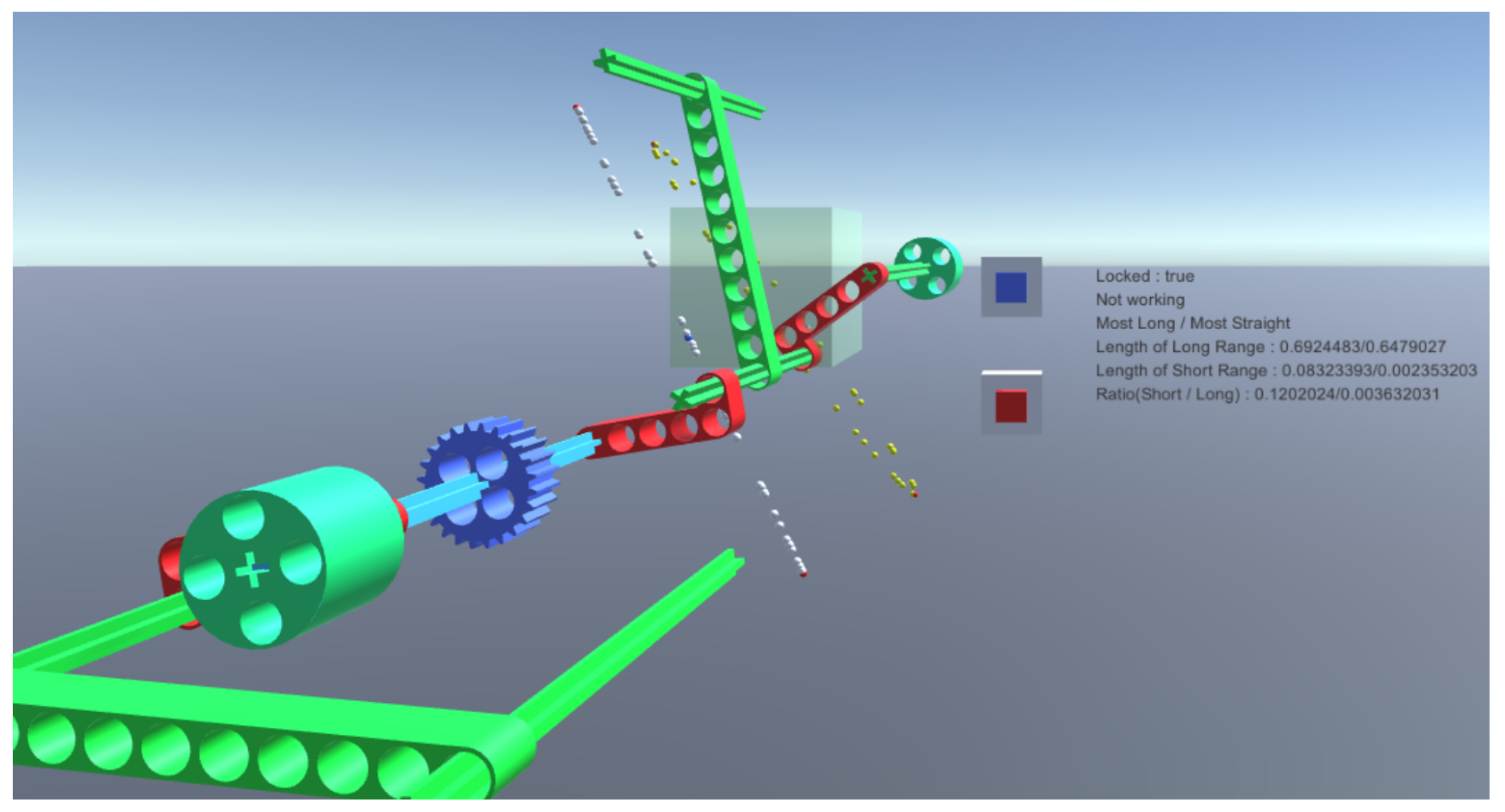
Two rounds of experiments were conducted and each experiment was conducted for 30 min. After each experiment, the subjects participated in surveys on each experiment for approximately 10 min. Ten students, who majored in software, computer engineering, or electronic engineering and expected to have little knowledge in mechanical engineering, participated as subjects in the experiments. The proposed interface can optimize various functions; to verify the effectiveness of this interface, participants were requested to complete the task of fabricating a mechanical assembly that performs a straight reciprocating motion. In the first experiment, participants were provided with simple assembly examples. This study evaluated if they achieved their tasks using only the direct manipulation interface. When they accomplished their tasks, the evaluation indices were improved. In the second experiment, they were provided with sample assembly examples offered in the first experiment and the final mechanical assemblies that they submitted in the first experiment. They were allowed to use both the direct manipulation interface and crossover operation interface during the second experiment. As in the first experiment, this study analyzed if they achieved their tasks. When they accomplished their tasks, the evaluation indices were improved. When the second experiment was terminated, this study classified the status of success or failure according to whether a part that showed a straight reciprocating motion existed among the parts composing the final mechanical assemblies that users submitted in the second experiment. The experimental results were then registered on the evaluation interface, and evaluation indices were obtained according to the following evaluation methods. Because the motor can represent only the rotational motion, the overlapping operation of several motors can present various motions ranging from an elliptical motion to a similar motion to a straight motion. When it is assumed that a mechanical assembly performs an elliptical motion, the longest distance and shortest distance between two points can be calculated on a track on which these points moved over time. A length ratio between both distance values is calculated to numerically indicate the closeness of an ellipse to straight motion. When the track is close to a circle under the condition of the longest distance divided by the shortest distance, the length ratio is close to 1. When the track is close to straight motion under the condition of the longest distance divided by the shortest distance, the length ratio is close to 0. Among the meshes comprising a part, a point drawing the track with the lowest length ratio and a point drawing the track with the highest length ratio are identified, respectively. Then, a point drawing the track with the lowest length ratio and a point drawing the track with the highest length ratio in each part are identified, respectively, represented in the VR space, and numerically indicated. The white track refers to the track with the lowest length ratio, whereas the yellow track refers to the track with the highest length ratio.
6.3. Results
Five participants out of ten in the experiments completed their tasks (see
Figure 9). One out of the ten participants completed the given task in the first experiment, and four more participants completed their tasks in the second experiment. Four out of the five task achievers did not accomplish their tasks at the direct manipulation interface but completed these tasks at the crossover operation interface. All the five task achievers designed mechanical assemblies that can represent an elliptical motion or a straight reciprocating motion (see
Table 2).
Details of the surveys conducted based on the participants are as follows. The fabrication of mechanical assemblies and motions were determined as survey keywords, and the participants were asked whether they easily got ideas on these keywords and whether they easily fabricated mechanical assemblies.
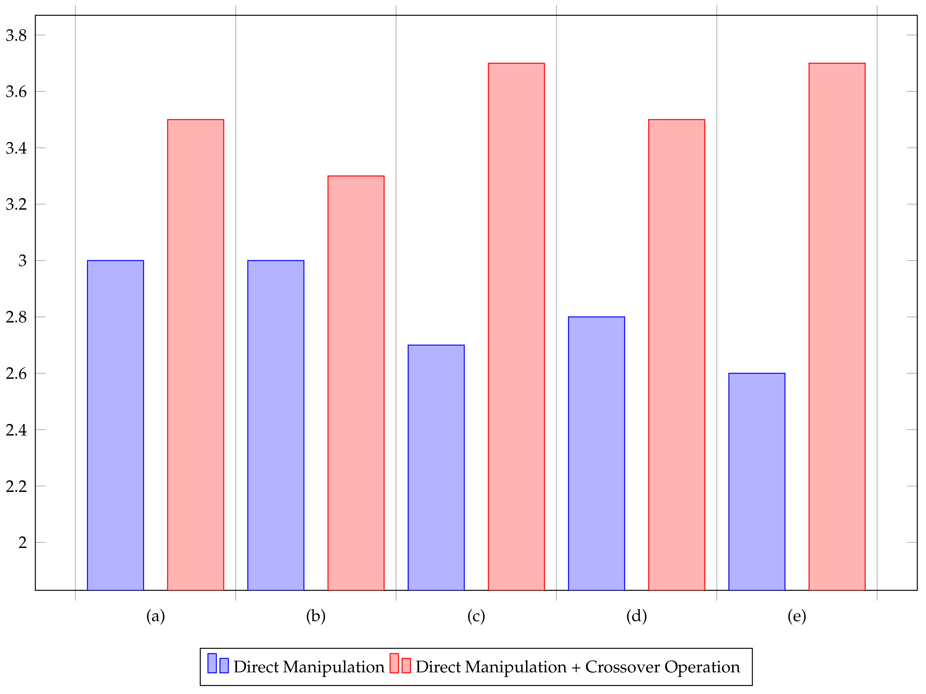
Table 3 lists up the survey questions. The surveys were conducted based on a five-point scale ranging from “very unlikely (Score 1)” to “very likely (Score 5)”. The survey results are depicted as bar graphs in
Figure 10.
This study analyzed the responses of participants and calculated the mean of the indices according to items. The calculation result indicated that most participants preferred a crossover operation environment to a direct manipulation environment. Particularly, participants showed more positive responses toward the crossover operation environment than those toward the direct manipulation environment in terms of the indices related to motions. The most remarkable difference is found in the responses to the last question, which relates to the participants’ satisfaction with whether or not they successfully assembled a machine that met the given requirements. This result can be regarded as a natural consequence because just 10% of the participants succeeded in the first experiment with only the direct manipulation interface whereas 50% of the participants succeeded in the second experiment with the additional evolutionary interface. Considering that the scores for the questions (a) and (b) related with the convenience of assembly does not exhibit notable differences, it is interpreted that the most important factor determining success or failure lies in making it easy to imagine the appropriate motions through the evolutionary interface, which is strongly evidenced by the significant difference in scores for the question (d). Such an interpretation is exactly in line with the direction of presenting the evolutionary interface as a creative tool for exploring new and effective design solutions in this paper.
The results of observing participants in experiments are as follows. A few participants were aware of the mechanical assembly structures that existed in the real world and can be used to achieve their tasks. However, they failed to accomplish their tasks because they could not fabricate the same structures in an experimental environment. Two participants were involved with this case, and one of them presented a similar mechanical assembly to the solution in the crossover operation environment. Then, 3D meshes of components can be duplicated in a mechanical assembly obtained as a result of the crossover operations. Thus, most participants performed crossover operations based on the same combination of mechanical assemblies for multiple times to derive results. When asked about the state of the task achievement, a majority of participants responded that they were not sure about the design direction in direct manipulation. However, most participants commented that the crossover operation environment helped them design mechanical assemblies and derive solutions. The experimental results verified that the proposed interface system based on crossover operation assisted even those with little knowledge of mechanical engineering to achieve their goals and provided practical support for users.
In addition, the comparison between the direct manipulation and the evolutionary interfaces, participants were asked some additional questions about their general satisfactions about the presented system. Most of the participants agreed that “it was more realitic to assemble in the presented VR system than in other PC or mobile applications” (scored 4.3). On the other hand, not so many participants agreed with that “it was easier to assemble in the presented VR system that in other PC or mobile applications” (scored 2.9). It was expected that assembling in 3D sapce would be easier to directly manipulate in an immersive virtual reality in a similar way to the real world than to operate through a conventional 2D screen. However, on the contrary to such an expectation, not an insignificant portion of the participants did not feel very comfortable with the assembly process using the VR interface. One possible interpretation of this result is that most of the participants did not feel familiar with the VR interface itself because they had little experience with VR equipment, such as head-mount displays and motion controllers. In fact, it is somewhat supported by the fact that some participants who had participated in VR-related research and were familiar with VR devices gave high scores to this question, while others who did not gave average or lower scores.
7. Conclusions
This study proposed a crossover operation interface system that can support non-experts to design mechanical assemblies that are operated according to the desired functions. To this end, this study established a VR assembly environment, which was similar to an assembly environment in the real world and provided a crossover operation interface that allowed users to assemble various structures of mechanical assemblies. When users face a lack of inspiration in the process of assembling mechanical assemblies in direct manipulation environment, they can use a crossover operation to obtain a new mechanical assembly combined with a different mechanical assembly. They can design a mechanical assembly that contains the desired functions by repeating the aforementioned process.
Based on this theory, this study implemented a VR environment and conducted an experiment under the VR environment that allowed the quantitative comparison between the direct manipulation interface and the evolutionary interface based on an assembly of a mechanical structure satisfying given objectives. The experimental result showed that a higher proportion of participants achieved their tasks successfully based on the evolutionary interface. Moreover, users experienced a lower level of difficulty in completing tasks and a higher level of satisfaction with the evolutionary interface combined with the direct manipulation interface than just with the direct manipulation interface.
One of the limitations in the presented system is that it requires users to handle a large number of mechanical structures simultaneously because each execution of the crossover operation yields dozens of new structures. Examining each new structure and determining whether to accept or not may take a considerable amount of time and effort. Some improvements on the interface might alleviate this problem, for example, by allowing users to easily and compactly rearrange the mechanical structures in 3D space or to quickly move among different mechanical structures located at distant places. As a more fundamental improvement, the inferior child machines could be automatically removed in advance according to a criterion that could quantitatively evaluate the degree of satisfaction with the requirements of the mechanical device to be made. This will provide a hybrid interface in the form of a mixture of interactive evolution and automated optimization.
This study established each mechanical assembly based on the unit of a gene. Therefore, the mechanical assembly obtained through the crossover operation could include fewer functions or show more incomplete performance than the reference assemblies when the structure of this assembly is complicated or its parts are divided according to the functions. Thus, further research should be conducted to carry out the crossover operation on both the complex structures of the mechanical assemblies according to the functional parts and components composing these functional parts to increase genetic variation. It is expected that the technical engineering design support based on the crossover operation will also be effectively applied, not only in the mechanical engineering field but also in other fields such as electronic circuit design.
Author Contributions
Conceptualization, K.H.L.; methodology, W.G.K. and K.H.L.; software, W.G.K.; validation, W.G.K. and K.H.L.; formal analysis, W.G.K. and K.H.L.; investigation, W.G.K. and K.H.L.; resources, W.G.K. and K.H.L.; data curation, W.G.K. and K.H.L.; writing—original draft preparation, W.G.K.; writing—review and editing, K.H.L.; visualization, W.G.K.; supervision, K.H.L.; project administration, K.H.L.; funding acquisition, K.H.L. All authors have read and agreed to the published version of the manuscript.
Funding
This work was supported by the National Research Foundation of Korea(NRF) grant funded by the Korea government(MSIT) (No. NRF-2021R1F1A1046373). This research also has been conducted by the Research Grant of Kwangwoon University in 2019.
Institutional Review Board Statement
The study was conducted in accordance with the Declaration of Helsinki, and the protocol was approved by the Ethics Committee of Kwangwoon University (7001546-20210701-HR(SB)-007-02).
Informed Consent Statement
All subjects gave their informed consent for inclusion before they participated in the study.
Data Availability Statement
Data available on request due to privacy or other restrictions.
Conflicts of Interest
The authors declare no conflict of interest.
References
- Beltagui, A.; Sesis, A.; Stylos, N. A bricolage perspective on democratising innovation: The case of 3D printing in makerspaces. Technol. Forecast. Soc. Chang. 2021, 163, 120453. [Google Scholar] [CrossRef]
- Lin, K.-Y.; Hsiao, H.-S.; Chang, Y.-S.; Chien, Y.-H.; Wu, Y.-T. The effectiveness of using 3D printing technology in STEM project-based learning activites. Eurasia J. Math. Sci. Technol. Educ. 2018, 14, em1633. [Google Scholar] [CrossRef]
- Bermano, A.H.; Funkhouser, T.; Rusinkiewicz, S. State of the art methods and representations for fabrication-aware design. Comput. Graph. Forum 2017, 36, 509–535. [Google Scholar] [CrossRef]
- Kadir, A.A.; Xu, X.; Hämmerle, E. Virtual machine tools and virtual machining-A technological review. Robot. Comput. Integr. Manuf. 2011, 27, 494–508. [Google Scholar] [CrossRef] [Green Version]
- Mendes, D.; Caputo, F.M.; Giachetti, A.; Ferreira, A.; Jorge, J. A survey on 3D virtual object manipulation: From the desktop to immersive virtual environments. Comput. Graph. Forum 2019, 38, 21–45. [Google Scholar] [CrossRef] [Green Version]
- Bowman, D.A.; Kruijff, E.; LaViola, J.J.; Poupyrev, I. 3D User Interfaces: Theory and Practice; Addison-Wesley: Redwood City, CA, USA, 2004. [Google Scholar]
- Bowman, D.A.; Hodges, L.F. An evaluation of techniques for grabbing and manipulating remote objects in immersive virtual environments. In Proceedings of the Symposium on Interactive 3D Graphics, Providence, RI, USA, 27–30 April 1997. [Google Scholar]
- Stoakley, R.; Conway, M.J.; Pausch, R. Virtual reality on a WIM: Interactive worlds in miniature. In Proceedings of the SIGCHI Conference on Human Factors in Computing Systems, Denver, CO, USA, 7–11 May 1995. [Google Scholar]
- Ha, W.; Choi, M.G.; Lee, K.H. Automatic control of virtual mirrors for precise 3D manipulation in VR. IEEE Access 2020, 8, 156274–156284. [Google Scholar] [CrossRef]
- Marks, J.; Andalman, B.; Beardsley, P.A.; Freeman, W.; Gibson, S.; Hodgins, J.; Kang, T.; Mirtich, B.; Pfister, H.; Ruml, W.; et al. Design galleries: A general approach to setting parameters for computer graphics and animation. In Proceedings of the SIGGRAPH, Los Angeles, CA, USA, 3–8 August 1997. [Google Scholar]
- Stanley, K.O.; Miikkulainen, R. Evolving neural networks through augmenting topologies. Evol. Comput. 2002, 10, 99–127. [Google Scholar] [CrossRef]
- Secretan, J.; Beato, N.; D’Ambrosio, D.B.; Rodriguez, A.; Campbell, A.; Stanley, K.O. Picbreeder: Evolving pictures collaboratively online. In Proceedings of the SIGCHI Conference on Human Factors in Computing Systems, Florence, Italy, 5–10 April 2008. [Google Scholar]
- Fisher, M.; Ritchie, D.; Savva, M.; Funkhouser, T.; Hanrahan, P. Example-based synthesis of 3D object arrangements. ACM Trans. Graph. 2012, 31, 1–11. [Google Scholar] [CrossRef]
- Desai, R.; Anderson, F.; Matejka, J.; Coros, S.; McCann, J.; Fitzmaurice, G.; Grossman, T. Geppetto: Enabling semantic design of expressive robot behaviors. In Proceedings of the CHI Conference on Human Factors in Computing Systems, Glasgow, UK, 4–9 May 2019. [Google Scholar]
- Swearngin, A.; Wang, C.; Oleson, A.; Fogarty, J.; Ko, A.J. Scout: Rapid exploration of interface layout alternatives through high-level design constraints. In Proceedings of the CHI Conference on Human Factors in Computing Systenms, Honolulu, HI, USA, 25–30 April 2020. [Google Scholar]
- Averkiou, M.; Kim, V.G.; Zheng, Y.; Mitra, N.J. ShapeSynth: Parameterizing model collections for coupled shape exploration and synthesis. Comput. Graph. Forum 2014, 33, 125–134. [Google Scholar] [CrossRef] [Green Version]
- Zheng, Y.; Cohen-Or, D.; Mitra, N.J. Smart variations: Functional substructures for part compatibility. Comput. Graph. Forum 2013, 32, 195–204. [Google Scholar] [CrossRef] [Green Version]
- Xu, K.; Zhang, H.; Cohen-Or, D.; Chen, B. Fit and diverse: Set evolution for inspiring 3D shape galleries. ACM Trans. Graph. 2012, 31, 1–10. [Google Scholar] [CrossRef]
- Goldberg, D.E. Genetic Algorithms in Search, Optimization and Machine Learning; Addison-Wesley: Boston, MA, USA, 1989. [Google Scholar]
- Doncieux, S.; Bredeche, N.; Mouret, J.-B.; Eiben, A.E. Evolutionary robotics: What, why, and where to. Front. Robot. AI 2015, 2, 4. [Google Scholar] [CrossRef] [Green Version]
- Sims, K. Evolving virtual creatures. In Proceedings of the SIGGRAPH, Orlando, FL, USA, 24–29 July 1994. [Google Scholar]
- Funes, P.; Pollack, J. Evolutionary body building: Adaptive physical designs for robots. Artif. Life 1998, 4, 337–357. [Google Scholar] [CrossRef]
- Park, J.H.; Lee, K.H. Computational design of modular robots based on genetic algorithm and reinforcement learning. Symmetry 2021, 13, 471. [Google Scholar] [CrossRef]
- Takagi, H. Interactive evolutionary computation: Fusion of the capabilities of EC optimization and human evalution. Proc. IEEE 2001, 89, 1275–1296. [Google Scholar] [CrossRef] [Green Version]
- Quiroz, J.C.; Louis, S.J.; Shankar, A.; Dascalu, S.M. Interactive genetic algorithm for user interface design. In Proceedings of the 2007 IEEE Congress on Evolutionary Computation, Singapore, 25–28 September 2007; pp. 1366–1373. [Google Scholar]
- Kim, H.-S.; Cho, S.-B. Application of interactive genetic algorithm to fashion design. Eng. Appl. Artif. Intell. 2000, 13, 635–644. [Google Scholar] [CrossRef] [Green Version]
- Globus, A.; Atsatt, S.; Lawton, J.; Wipke, T. JavaGenes: Evolving graphs with crossover. NASA Tech. Rep. 2000. [Google Scholar]
- Carballido, J.A.; Ponzoni, I.; Brignole, N.B. CGD-GA: A graph-based genetic algorithm for sensor network design. Inf. Sci. 2007, 177, 5091–5102. [Google Scholar] [CrossRef]
- Cuk, A.; Bezdan, T.; BAcanin, N.; Zivkovic, M.; Venkatachalam, K.; Rashid, T.A.; Devi, V.K. Feedforward multi-layer perceptron training by hybridized method between genetic algorithm and artificial bee colony. In Data Science and Data Analytics; Tyagi, A.K., Ed.; Chapman and Hall/CRC: New York, NY, USA, 2021; pp. 279–292. [Google Scholar]
- Xue, X.; Zhang, Z. Matching large-scale biomedical ontologies with central concept based partitioning algorithm and Adaptive Compact Evolutionary Algorithm. Appl. Soft Comput. 2021, 106, 107343. [Google Scholar] [CrossRef]
- Hanh, P.T.H.; Thanh, P.D.; Binh, H.T.T. Evolutionary algorithm and multifactorial evolutionary algorithm on clustered shortest-path tree problem. Inf. Sci. 2021, 553, 280–304. [Google Scholar] [CrossRef]
- Daham, H.A.; Mohammed, H.J. An evolutionary algorithm approach for vehicle routing problems with backhauls. Mater. Today Proc. 2021. [Google Scholar] [CrossRef]
| Publisher’s Note: MDPI stays neutral with regard to jurisdictional claims in published maps and institutional affiliations. |
© 2022 by the authors. Licensee MDPI, Basel, Switzerland. This article is an open access article distributed under the terms and conditions of the Creative Commons Attribution (CC BY) license (https://creativecommons.org/licenses/by/4.0/).


