Article

An Adaptive Neuro-Fuzzy Model for Attitude Estimation and Control of a 3 DOF System

1
Department of Kinesiology, Shenyang Sport University, Shenyang 110102, China
2
Department of Mechanical Engineering, University of Illinois at Chicago, Chicago, IL 60607, USA
3
Department of Mechanical Engineering, State University of New York at Binghamton, 4400 Vestal Parkway, Binghamton, NY 13902, USA
4
Key Laboratory of Structural Dynamics of Liaoning Province, College of Sciences, Northeastern University, Shenyang 110819, China
*
Authors to whom correspondence should be addressed.
Mathematics 2022, 10(6), 976; https://doi.org/10.3390/math10060976
Submission received: 18 February 2022 / Revised: 15 March 2022 / Accepted: 16 March 2022 / Published: 18 March 2022
(This article belongs to the Special Issue Applied Computing and Artificial Intelligence)

Abstract

:
In recent decades, one of the scientists’ main concerns has been to improve the accuracy of satellite attitude, regardless of the expense. The obvious result is that a large number of control strategies have been used to address this problem. In this study, an adaptive neuro-fuzzy integrated system (ANFIS) for satellite attitude estimation and control was developed. The controller was trained with the data provided by an optimal controller. Furthermore, a pulse modulator was used to generate the right ON/OFF commands of the thruster actuator. To evaluate the performance of the proposed controller in closed-loop simulation, an ANFIS observer was also used to estimate the attitude and angular velocities of the satellite using magnetometer, sun sensor, and data gyro data. However, a new ANFIS system was proposed that can jointly control and estimate the system attitude. The performance of the proposed controller was compared to the optimal PID controller in a Monte Carlo simulation with different initial conditions, disturbance, and noise. The results show that the proposed controller can surpass the optimal PID controller in several aspects including time and smoothness. In addition, the ANFIS estimator was examined and the results demonstrate the high ability of this designated observer. Consequently, evaluating the performance of PID and the proposed controller revealed that the proposed controller consumed less control effort for satellite attitude estimation under noise and uncertainty.

1. Introduction

Satellite attitude control plays a significant role in most space missions. Therefore, the development of an accurate and stable controller is an essential part of conducting a space mission [1,2,3,4,5,6,7,8]. The most advanced satellite attitude control techniques use the concept of quaternion feedback [9,10,11,12]. However, various linear and nonlinear attitude control strategies based on quaternion feedback have been investigated [13,14]. The quaternion feedback approach is also used to stabilize the attitude of microsatellites [15].
In recent years, many control techniques have been proposed for satellite attitude control in the presence of uncertainty and disturbance [16,17]. Li et al. [18] proposed a robust finite time control algorithm for controlling satellite attitude in the presence of uncertainty; and Xiao et al. [19] developed a control approach with a simple structure to perform an attitude tracking maneuver for rigid satellites in the case of disturbances and uncertain inertia parameters. In another study, Vatankhahghadim and Damaren [20] proposed a linear passivity-based controller design for hybrid attitude control of spacecraft using magnetic torques and thrusters.
Several different types of optimal controllers have been used to enhance the performance of the satellite attitude control system. In order to enhance the pointing accuracy of a small satellite, an attempt was made to optimize the attitude control model based on the optimal control algorithm [21]. In another study, the optimal magnetic attitude control for small satellites was studied [22]. Moreover, Arantes et al. [23] tried to analyze and design a reaction thruster attitude controller and then improve the performance of the control subsystem. All these optimal control design algorithms inevitably led to a specific mathematical model, leading to inappropriate behavior compared to external pulses in the comparison simulation state. It is noteworthy to mention that an optimal controller may not guarantee the stability of the closed-loop system in the presence of uncertainties.
The adaptive control method is one of the most powerful approaches that can deal with the problem of system uncertainty. In this regard, Wen et al. [24] proposed a novel adaptive control method for the spacecraft’s attitude tracking control problem with inertia uncertainties. Moreover, Lee and Singh [25] proposed an adaptive controller in order to control the satellite attitude by solar radiation pressure. In another research, they presented a novel adaptive controller for attitude control of satellites with large uncertainties in the system parameters utilizing solar radiation pressure [26]. All of these adaptive control algorithms are model-based, and although they are able to deal accurately with uncertainties, they are incapable of dealing with different dynamic models. The problem of satellite attitude determination has been extensively studied, and has been the main concern of many studies in recent decades [27,28,29]. In a study by Kouyama et al. [30], they proposed an automated and robust scheme to determine the satellite attitude, which of course follows an exact map projection. They employed this method in combination with the classic onboard sensors. In another study, Wu et al. [13] proposed a method by which the problem of orientation based on a single sensor observation could be solved.
The enormous ability of fuzzy logic to solve various mathematical problems of modeling, control, and estimation is undeniable. Daley et al. [31] utilized the self-organizer fuzzy logic controller (SOC) for attitude control of a flexible satellite with significant dynamic coupling of the axes that cannot be modeled easily. In another paper, Mukherjee et al. [32] employed fuzzy logic to control the attitude of Earth-pointing satellites, in which they used the genetic algorithm to optimize the performance of their proposed nonlinear fuzzy PID controller. In other research, Huo et al. [33] proposed an adaptive fuzzy fault tolerance attitude control for a rigid spacecraft. In recent years, fuzzy logic has been used for a variety of satellite attitude estimation purposes [34]. However, Ran et al. [35] studied an adaptive fuzzy fault tolerance control for rigid spacecraft attitude maneuvers. Furthermore, Sun et al. [36] utilized an adaptive fuzzy estimator for spacecraft attitude determination.
In this paper, an ANFIS (adapted neuro-fuzzy inference system) [37] controller was introduced to control and estimate the satellite attitude. However, to the best of the authors’ knowledge, no study in the literature has been conducted on the integrated control and estimation of satellite attitude using ANFIS, which is a kind of artificial neural network and is based on the Takagi–Sugeno fuzzy inference system. The most significant advantage of the proposed model is the elimination of interphase (sensor equations and equations used to calculate quaternion errors). This, in turn, eliminates systematic errors and noise that are unavoidable in classical approaches. Consequently, the ANFIS control method is mostly applicable in terms of measurement noise, model uncertainty, and external disturbance [38].
The rest of this paper is organized as follows. First, a summary of the satellite attitude dynamics is given. A brief overview of the optimal PID controller design for control systems is then given. Next, the general ANFIS structure and the learning algorithms are discussed. Subsequently, structures of ANFIS controller and satellite attitude estimator are given. Finally, an ANFIS integrated control and estimation subsystem are introduced to reduce the complexity of the control system. The usefulness of this model is then examined by comparing the proposed model results with those of the classical controller.

2. Modeling of System

2.1. Satellite Dynamics Model

In this section, we introduce equations of motion of a satellite with the Euler equation and quaternion kinematics. The Euler equation of the rigid body satellite attitude around its principal axes coordinates is [39]:
I 1 ω ˙ 1 = M c 1 + M d 1 I 3 I 2 ω 2 ω 3 I 2 ω ˙ 2 = M c 2 + M d 2 I 1 I 3 ω 1 ω 3 I 3 ω ˙ 3 = M c 3 + M d 3 I 2 I 1 ω 2 ω 1
where ω 1 ,   ω 2 , and ω 3 are the elements of the angular velocity vector of the satellite. In addition, I1, I2, and I3 are the moments of inertia about the principal axes. M c and M d are the control and disturbance moments, respectively, which are expressed in the body frame.
For kinematic representation, the quaternion vector q ¯ = q 1 , q 2 , q 3 , q 4 T is utilized, which is defined as follows:
q 1 q 2 q 3 = sin θ 2 e 1 e 2 e 3     ,     q 4 = cos θ 2  
where θ is the rotation angle about the Euler axis e ¯ = e 1 , e 2 , e 3 . The kinematic differential equations for quaternions are as follows:
q ˙ 1 q ˙ 2 q ˙ 3 q ˙ 4 = 1 2 0 ω 3 ω 2 ω 1 ω 3 0 ω 1 ω 2 ω 2 ω 1 0 ω 3 ω 1 ω 2 ω 3 0 q 1 q 2 q 3 q 4

2.2. Measurements

The sun sensor and the magnetometer were used as reference sensors in this study to estimate the setting. In order to simulate the magnetometer sensor (magnetic field), height, latitude, longitude date, were considered as inputs and the magnetic field vector can be calculated as inertia frame B ¯ I using the IGRF11 model [40]. Therefore, the magnetic field is transformed into the body frame B ¯ B including a random white noise n ¯ B :
B ¯ B = C I B B ¯ I + n ¯ B
The rotation matrix C I B can be calculated using the quaternion vector as follows:
C I B = 1 2 q 2 2 + q 3 2 2 q 1 q 2 + q 3 q 4 2 q 1 q 3 + q 2 q 4 2 q 2 q 1 + q 3 q 4 1 2 q 1 2 + q 3 2 2 q 2 q 3 + q 1 q 4 2 q 3 q 1 + q 2 q 4 2 q 3 q 2 + q 1 q 4 1 2 q 1 2 + q 2 2
The attitude measurement only needs the direction of the magnetic field, which can be calculated as follows:
u ¯ B B = B ¯ B / B ¯ B
The sun vector direction in inertial frame u ¯ s I can be found by the following formulation [41]:
u ¯ S I = cos λ e c l i p t i c cos ε sin λ e c l i p t i c sin ε sin λ e c l i p t i c T
where
JD = 367 year INT 7 year + INT month + 9 12 4 + INT 275 month 9 + day + 1721013.5 + second 60 + minute 60 + hour 24
T = JD 2451545.0 / 36525   ,
λ M = 280.4606184 ° + 36000.77005361 T ,
M = 357.5277233 ° + 35999.05034 T ,
λ e c l i p t i c = λ M + 1.914666471 °   sin M + 0.019994643 sin 2 M ,
ε = 23.439291 ° 0.0130042 T ,
In the above equations, JD is Julian Day based on the date and time (year, month, day, hour, minute, and second); T is the Julian centuries; λ M is mean longitude of the sun; M is the mean anomaly of the sun; λ e c l i p t i c is the ecliptic longitude of the sun; and ε is the tilt angle of the Earth rotation axis.
Similar to the magnetometer, the output of the sun sensor as the direction of the sun vector in body frame u ¯ S B can be estimated as follows:
u ¯ S B = C I B u ¯ S I + n ¯ S
Furthermore, to provide the angular velocity measurements, a three-axis rate-gyro with random white noise was used.

3. Adaptive Neural Fuzzy Inference System

3.1. Fuzzy Logic

Most traditional tools for modeling, thinking, and arithmetic are crisp, deterministic, and precise in character, so yes or no types instead of more or less types. In conventional dual logic, for example, a statement may be true or false and nothing in between. For the first time, L.A. Zadeh [42] proposed a fuzzy logic that contained “true”, “false”, and “partially true”. He emphasized that real situations are often not clear and deterministic and cannot be described accurately.
A fuzzy control system is based on fuzzy logic, which analyzes input values in the form of logical variables that assume continuous values between 0 and 1. Rather than designing algorithms that explicitly define the control action as a function of the control input variables, the developer of a fuzzy controller writes rules that associate the input variables with the control variables through expressions of linguistic variables [43,44]. After all rules have been defined, the control process begins with the calculation of all rule consequences. Then, the consequences are summarized into a fuzzy set that describes the possible control actions.

3.2. ANFIS

In general, the fuzzy control logic has two main approaches: (1) Mamdani [45] and (2) Takagi–Sugeno [46]. The basis of ANFIS as an adaptive network-based fuzzy system is the Takagi–Sugeno fuzzy system method [37,47]. Its inference system corresponds to a set of fuzzy IF–THEN rules that have a learning ability to approximate non-linear functions. ANFIS is a combination of neural networks and fuzzy systems. However, ANFIS has become a very powerful simulation method that uses both fuzzy and neural network methods [48]. Recently, ANFIS modeling has become widespread in various space missions [49,50,51].
The main characteristic of the ANFIS controller is the ability to handle inaccuracy and uncertainty, which allows the use of real data and, more importantly, the design of a controller based on the provided real data [14,52]. The other considerable superiority of the ANFIS system is the required number of input variables for control and estimation. Simplicity of modeling compared to classical modeling, along with the superiority of this method in the presence of noise and uncertainty compared to PID controllers, which makes our proposed model more accurate.
ANFIS has five layers (as shown in Figure 1) as follows:
Layer 1: Define membership function of input variables.
O 1 , i = μ A i x   f o r   i = 1 , 2
O 1 , i = μ B i 2 x   f o r   i = 3 , 4
Layer 2: Product of the membership function for each input.
O 2 , i = ω i = μ A i x   μ B i x   i = 1 , 2
Layer 3: Normalize the output of layer 2.
O 3 , i = ω ¯ i = ω i ω 1 + ω 2   i = 1 , 2
Layer 4: The output of this layer is:
O 4 , i = ω ¯ i f i = ω ¯ i p i x + q i y + r i
Layer 5: The output of this layer is the summation of all outputs in layer 4.
O 5 , i = ω ¯ i f i = ω i f i ω i

3.3. Hybrid Learning Algorithm

Least square gradient reduction was used to train the ANFIS system (locating the membership function parameters) and the pattern between the input and the output data provided by an optimal PID controller.
Each learning level can be divided into two parts. In the forward stage, the inputs and outputs of each layer are calculated and the optimal coefficients are provided. Then, in the reverse stage, the parameters of the ANFIS system are updated.

3.4. Optimal PID Controller

The control moment vector by using the PID controller can be calculated as follows:
M c = K p q e + K d ω + K q q e d t + K ω ω d t
where q e is the quaternion error and can be obtained from the following equation [39]:
q ¯ e q 4 = q 1 e q 2 e q 3 e q 4 e = q 4 c q 3 c q 2 c q 1 c q 3 c q 4 c q 1 c q 2 c q 2 c q 1 c q 4 c q 3 c q 1 c q 2 c q 3 c q 4 c q 1 q 2 q 3 q 4
where q c s are the quaternions of the command attitude.
The control gains K p ,   K d ,   K q in Equation (9) are optimized in order to minimize the following cost function:
J = i = 1 3 ω i + i = 1 3 q e i d t
By considering the following constraint as:
M c M c m a x
Consequently, this constraint guarantees the appropriate signal command to input the modulator for ON–OFF command of the thrusters with torque M c m a x .

4. ANFIS Controller and Estimator

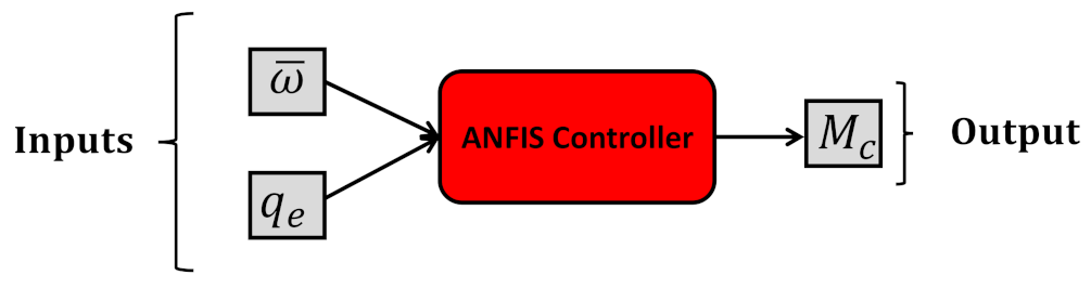
4.1. ANFIS Controller

The aim of this training is to model an optimal PID controller as close as possible. The control input variables are angular velocity and quaternion errors, and the control output variable is the control torque M C (as shown in Figure 2).
After the input and output variables are supplied by a system with PID controller, the collection of these data is repeated several times, taking into account 15 different initial conditions (each simulation for 20 s with 0.01 s sampling time). This means that the initial quaternions and initial angular velocities are changed to provide a wide range of data for ANFIS learning. Thereafter, the ANFIS controller training process begins and the ANFIS system learns the path from the inputs to the outputs. Now, the ANFIS controller can work with all initial conditions.

4.2. ANFIS Estimator

In this study, we utilized sun sensor and magnetometer outputs to estimate attitude. Therefore, data for ANFIS estimation learning from these two sensors were provided both in the body (sensor) and in the inertia frame (calculation) (as shown in Figure 3). However, several different scenarios were considered to provide a large database for learning the ANFIS estimator.

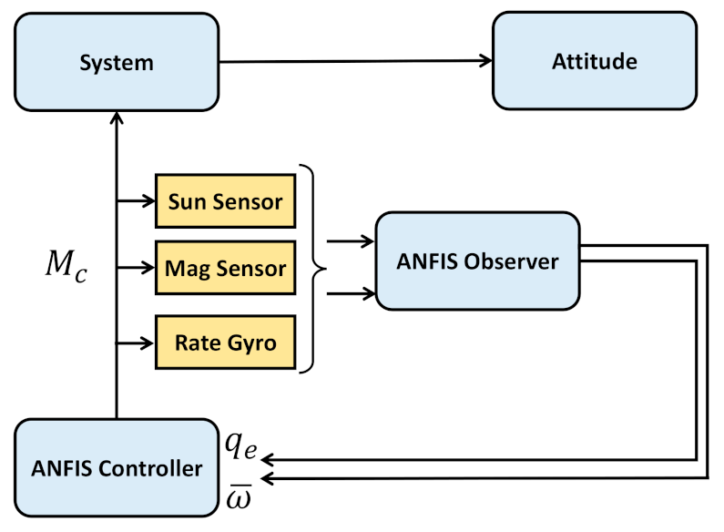
4.3. Combined Control and Estimation Using ANFIS

In this study, both the ANFIS estimator and ANFIS controller were used in a closed loop simulation. The nesting simulations show the performance of these two ANFIS subsystems working simultaneously (as shown in Figure 4).

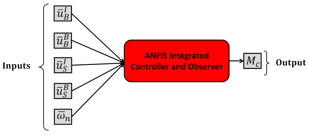
4.4. Integrated Control and Estimation Using ANFIS

As mentioned in the introduction, the main purpose of this study was to evaluate the performance of an ANFIS system as a combination of estimator and controller instead of two separate subsystems (ANFIS estimator and ANFIS controller). As shown in Figure 5, for the proposed ANFIS subsystem, input variables are the inputs of the estimator (sensor data), and output variables are the outputs of the controller (control torque). In fact, the ANFIS integrated control and estimation subsystem receives data read by the sun sensor and the magnetic sensor as input variables and then passes the control torque directly to the system dynamics, as shown in Figure 6).

5. Evaluation of ANFIS Control and Estimation

To study the performance of attitude estimation and the control of satellites using ANFIS, a satellite with the moments of inertia that presented in Table 1 was considered. For all simulations, the final simulation duration time was selected to be 20 s, and the sampling time for estimation was 0.01 s. The system initial conditions and the desire attitude are provided in Table 2.

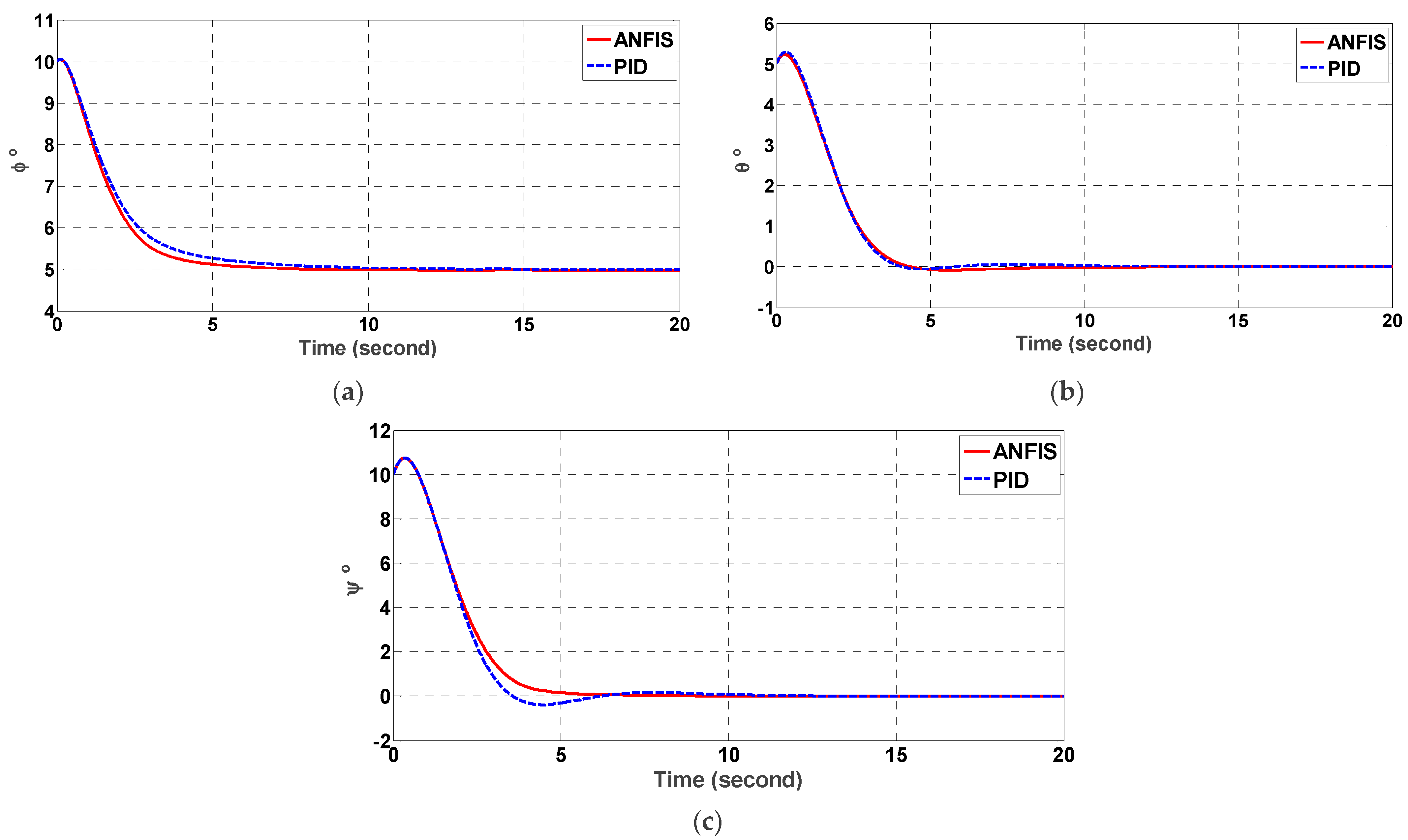
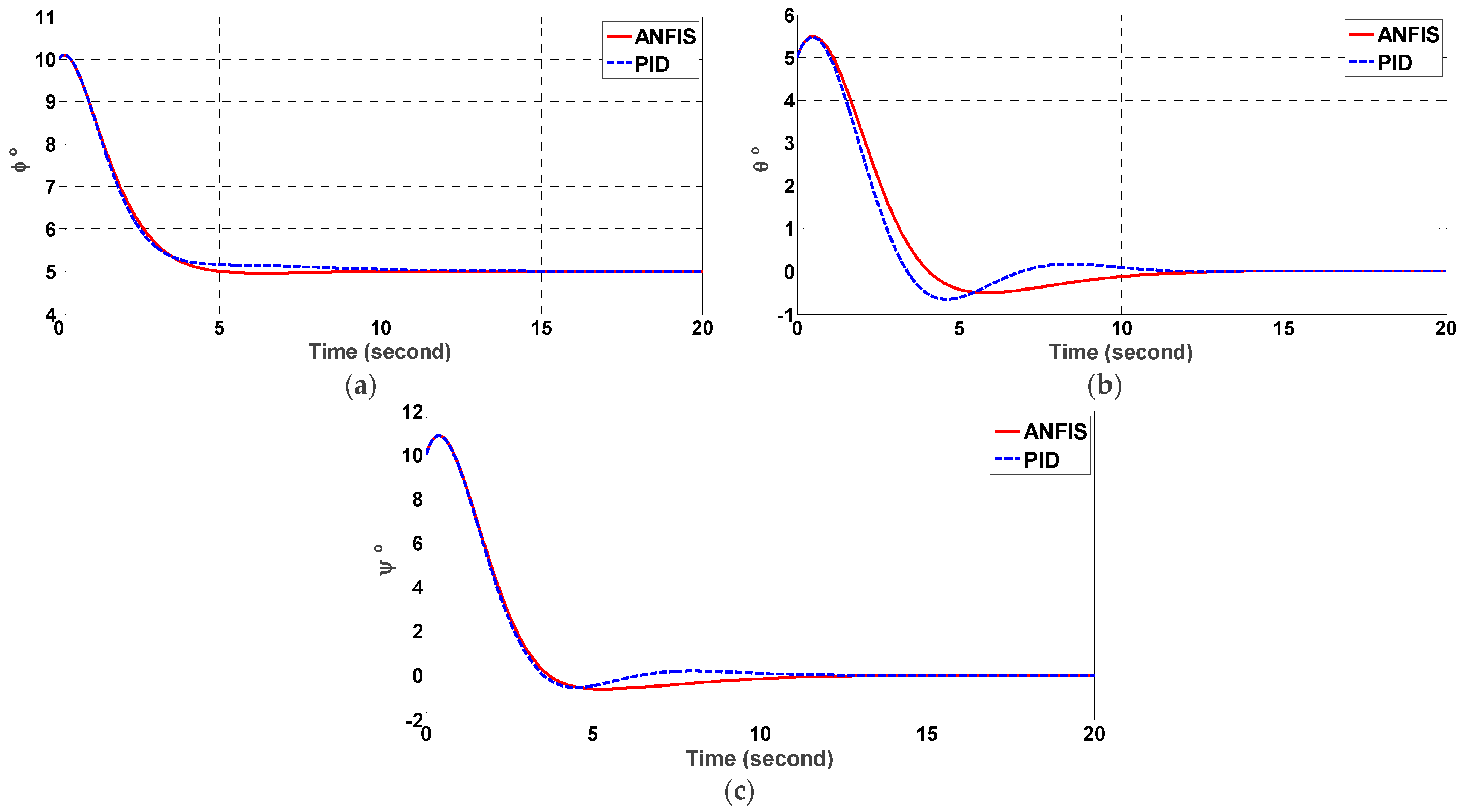
5.1. ANFIS Performance Comparison

As the simulations are presented for the stabilization of satellite attitude on zero condition, the most important characteristics of the results are the settling time of control, the control effort (fuel consumption), and the steady state error. Therefore, these characteristics are considered as the criteria for a comparison of the results.
The comparison of time histories of control moments for PID and ANFIS in the presence of noise and uncertainty are shown in Figure 7 and Figure 8, respectively. The trajectory of the Euler angles are also presented in Figure 9 and Figure 10. As shown in Figure 7, it can be seen that the PID controller is noisy and the ANFIS controller design method produces smoother control actions. Moreover, the trajectory of the attitude angles using PID controller has larger over-shoot values. As a result, the attitude angles are smoother and they can quickly reach the desired values.
The numerical results of the comparison of the ANFIS controller and PID controller are provided in Table 3 with/without noise and uncertainty. It is clear from this table that the fuel consumption of the ANFIS controller was 5% lower than PID, even if there is no uncertainty and/or measurement noise. The presence of noise and uncertainty induced more fuel consumption (14% and 9%, respectively). Accordingly, the ANFIS controller used less control effort (fuel) in all situations (noise and uncertainty).
The settling time with 1% error is listed in Table 4 for both controllers. The improvement in settling time using ANFIS over the PID was more obvious. In some cases, the settling time of ANFIS was almost half the PID, which is very important in space systems.

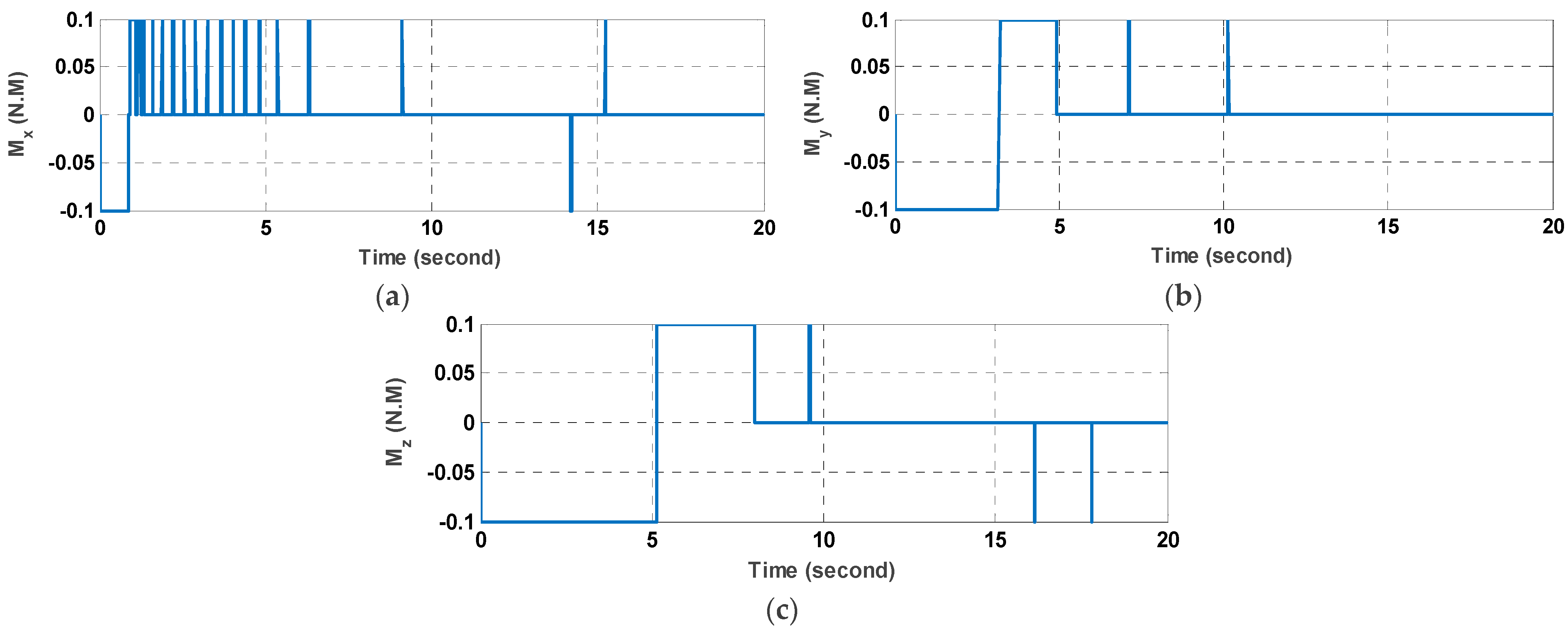
5.2. Command Modulation

To evaluate the ANFIS controller results for the real thruster actuator, the control moments should be converted to ON–OFF commands. However, a PWPF (pulse-width pulse-frequency) modulator is used to transform the continuous control moment command to the ON–OFF commands. The trajectory of the attitude angles and the thruster commands are shown in Figure 11 and Figure 12, respectively. It is clear that the limit of thrust results in a slower approach to the final attitudes. However, the results are acceptable considering the model uncertainty and measurement noise.

5.3. Monte Carlo Simulation

To analyze the robustness of the proposed integrated ANFIS estimator and controller, a Monte-Carlo simulation was conducted. A random initial condition (between −15 and +15 degrees) was considered in addition to the random noise and random uncertainty (I 1 Kg·m2). The attitude control error of Euler angles of time = 20 s are shown for each Monte-Carlo simulation and the average and 3σ (standard deviation) until each iteration are shown in Figure 13 for 200 iterations. The maximum control error was less than 0.02 degrees, which is considerably low.

6. Conclusions

In this study, an ANFIS (adaptive neuro-fuzzy inference system) controller and estimator was proposed in order to estimate and control the attitude of a satellite. However, the ANFIS controller was trained using an optimal PID. The other significant ability of the proposed system is in estimating the necessary states accurately via an ANFIS observer. To train the observer, a satellite in several different conditions (noise and uncertainty) was considered. The performance of the ANFIS controller and estimator was also compared with the PID controller in the presence of uncertainties and noises.
A comparison oof the performance of the PID and ANFIS controllers showed that the proposed ANFIS controller consumed less control effort (fuel) in all situations (noise and uncertainty). In addition, the proposed controller outputs behaved smoother and reached stability in a shorter time interval than the PID controller. Likewise, system outputs (control angles) were smoother and reached the desired angles faster. Furthermore, using an ANFIS estimator in the system showed that despite its simple design, it can estimate the states, even in the presence of uncertainty. Results of using the synchronous control and estimation ANFIS simulator showed that although both stages (control and estimation) were conducted in one-step, the performance of the integrated system was similar to the combined controller and estimator. Due to the proven abilities of the ANFIS controller and observer, it can be concluded that it is able to work with black box systems. It means that the determined dynamic is not essential, which makes it possible to be used for unknown space bodies (e.g., space debris) as well as fast parameter varying space objects (e.g., space robots and manipulators). In this study, we aimed to utilize as less feedback parameters as possible while the simplicity and practicability of determining those parameters were considered. Future work will focus on the attitude control of flexible satellites with multi-section appendages as well as considering fluid fuel sloshing using the ANFIS controller.

Author Contributions

Conceptualization, M.C. and S.M.A.; methodology, T.Z. and X.W.; software, S.M.A. and M.C.; validation, X.W., T.Z. and M.C.; formal analysis, S.M.A.; investigation, S.M.A. and M.C.; resources, T.Z.; data curation, X.W.; writing—original draft preparation, S.M.A. and M.C.; writing—review and editing, M.C. and S.M.A.; visualization, S.M.A.; supervision, T.Z.; project administration, X.W.; funding acquisition, T.Z. All authors have read and agreed to the published version of the manuscript.

Funding

This study is funded by the key R&D plan of China for Winter Olympics (No. 2021YFF0306401), and the Key Special Project of the National Key Research and Development Program “Technical Winter Olympics” (2018YFF0300502 and 2021YFF0306400).

Institutional Review Board Statement

Not applicable.

Informed Consent Statement

Not applicable.

Data Availability Statement

Not applicable.

Conflicts of Interest

The authors declare no conflict of interest.

References

  1. Ismail, Z.; Varatharajoo, R. A study of reaction wheel configurations for a 3-axis satellite attitude control. Adv. Sp. Res. 2010, 45, 750–759. [Google Scholar] [CrossRef]
  2. Inamori, T.; Sako, N.; Nakasuka, S. Compensation of time-variable magnetic moments for a precise attitude control in nano- and micro-satellite missions. Adv. Sp. Res. 2011, 48, 432–440. [Google Scholar] [CrossRef]
  3. Siahpour, S.; Zand, M.M.; Mousavi, M. Dynamics and vibrations of particle-sensing MEMS considering thermal and electrostatic actuation. Microsyst. Technol. 2018, 24, 1545–1552. [Google Scholar] [CrossRef]
  4. Mousavi, M.; Rahnavard, M.; Haddad, S. Observer based fault reconstruction schemes using terminal sliding modes. Int. J. Control 2020, 93, 881–888. [Google Scholar] [CrossRef]
  5. Mousavi, M.; Rahnavard, M.; Yazdi, M.R.H.; Ayati, M. On the Development of Terminal Sliding Mode Observers. In Proceedings of the 26th Iranian Conference on Electrical Engineering (ICEE), Mashhad, Iran, 8–10 May 2018; pp. 951–956. [Google Scholar] [CrossRef]
  6. Mousavi, M.; Rahnavard, M.; Ayati, M.; Hairi Yazdi, M.R. Terminal sliding mode observers for uncertain linear systems with matched disturbance. Asian J. Control 2019, 21, 377–386. [Google Scholar] [CrossRef] [Green Version]
  7. Sajjadi, M.; Chahari, M.; Pishkenari, H.N. Imaging performance of trolling mode atomic force microscopy: Investigation of effective parameters. Arch. Appl. Mech. 2022, 2022, 1–20. [Google Scholar] [CrossRef]
  8. Rahnavard, M.; Ayati, M.; Hairi Yazdi, M.R.; Mousavi, M. Finite time estimation of actuator faults, states, and aerodynamic load of a realistic wind turbine. Renew. Energy 2019, 130, 256–267. [Google Scholar] [CrossRef]
  9. Sajjadi, M.; Pishkenari, H.N.; Vossoughi, G. Dynamic modeling of trolling-mode AFM: Considering effects of cantilever torsion, nanoneedle flexibility and liquid-nanoneedle interactions. Ultramicroscopy 2017, 182, 99–111. [Google Scholar] [CrossRef]
  10. Fossen, T.I. Marine Control Systems. J. Guid. Control Dyn. 2002, 28, 1689–1699. [Google Scholar]
  11. Sajjadi, M.; Chahari, M.; Pishkenari, H.N.; Vossoughi, G. Designing nonlinear observer for topography estimation in trolling mode atomic force microscopy. J. Vib. Control 2021. [Google Scholar] [CrossRef]
  12. Chahari, M.; Sajjadi, M. Modeling of eccentric nanoneedle in trolling-mode atomic force microscope. Microsc. Res. Tech. 2020, 84, 639–655. [Google Scholar] [CrossRef] [PubMed]
  13. Wu, J.; Zhou, Z.; Li, R.; Yang, L.; Fourati, H. Attitude determination using a single sensor observation: Analytic quaternion solutions and property discussion. IET Sci. Meas. Technol. 2017, 11, 731–739. [Google Scholar] [CrossRef]
  14. Abtahi, S.; Sharifi, M. Machine learning method to control and observe for treatment and monitoring of hepatitis b virus. arXiv 2020, arXiv:2004.09751. [Google Scholar]
  15. Kristiansen, R.; Nicklasson, P.J. Satellite attitude control by quaternion-based backstepping. In Proceedings of the 2005, American Control Conference, Portland, OR, USA, 8–10 June 2005; pp. 907–912. [Google Scholar]
  16. Kang, J.; Zhu, Z.H.; Wang, W.; Li, A.; Wang, C. Fractional order sliding mode control for tethered satellite deployment with disturbances. Adv. Sp. Res. 2017, 59, 263–273. [Google Scholar] [CrossRef]
  17. Aleksandrov, A.Y.; Aleksandrova, E.B.; Tikhonov, A.A. Stabilization of a programmed rotation mode for a satellite with electrodynamic attitude control system. Adv. Sp. Res. 2018, 62, 142–151. [Google Scholar] [CrossRef]
  18. Li, Y.; Ye, D.; Sun, Z. Robust finite time control algorithm for satellite attitude control. Aerosp. Sci. Technol. 2017, 68, 46–57. [Google Scholar] [CrossRef]
  19. Xiao, B.; Yin, S.; Wu, L. A structure simple controller for satellite attitude tracking maneuver. IEEE Trans. Ind. Electron. 2016, 64, 1436–1446. [Google Scholar] [CrossRef]
  20. Vatankhahghadim, B.; Damaren, C.J. Magnetic attitude control with impulsive thrusting using the hybrid passivity theorem. J. Guid. Control Dyn. 2017, 40, 1860–1876. [Google Scholar] [CrossRef] [Green Version]
  21. Fan, Z.; Hua, S.; Chundi, M.; Yuchang, L. An optimal attitude control of small satellite with momentum wheel and magnetic torquerods. In Proceedings of the 4th World Congress on Intelligent Control and Automation (Cat. No. 02EX527), Shanghai, China, 10–14 June 2002; Volume 2, pp. 1395–1398. [Google Scholar]
  22. Wisniewski, R.; Markley, F.L. Optimal magnetic attitude control. IFAC Proc. Vol. 1999, 32, 7991–7996. [Google Scholar] [CrossRef]
  23. Arantes, G.; Martins-Filho, L.S.; Santana, A.C. Optimal on-off attitude control for the Brazilian multimission platform satellite. Math. Probl. Eng. 2009, 2009, 750945. [Google Scholar] [CrossRef] [Green Version]
  24. Wen, H.; Yue, X.; Li, P.; Yuan, J. Fast spacecraft adaptive attitude tracking control through immersion and invariance design. Acta Astronaut. 2017, 139, 77–84. [Google Scholar] [CrossRef]
  25. Lee, K.W.; Singh, S.N. 1 adaptive attitude control of satellites in elliptic orbits using solar radiation pressure. Proc. Inst. Mech. Eng. Part G J. Aerosp. Eng. 2014, 228, 611–626. [Google Scholar] [CrossRef]
  26. Lee, K.W.; Singh, S.N. Non-certainty-equivalent adaptive satellite attitude control using solar radiation pressure. Proc. Inst. Mech. Eng. Part G J. Aerosp. Eng. 2009, 223, 977–988. [Google Scholar] [CrossRef]
  27. Zhang, J.; Swain, A.K.; Nguang, S.K. Robust sensor fault estimation scheme for satellite attitude control systems. J. Franklin Inst. 2013, 350, 2581–2604. [Google Scholar] [CrossRef]
  28. Cao, L.; Li, H. Unscented predictive variable structure filter for satellite attitude estimation with model errors when using low precision sensors. Acta Astronaut. 2016, 127, 505–513. [Google Scholar] [CrossRef]
  29. Zeng, Z.; Zhang, S.; Xing, Y.; Cao, X. Robust adaptive filter for small satellite attitude estimation based on magnetometer and gyro. Abstr. Appl. Anal. 2014, 2014, 159149. [Google Scholar] [CrossRef] [Green Version]
  30. Kouyama, T.; Kanemura, A.; Kato, S.; Imamoglu, N.; Fukuhara, T.; Nakamura, R. Satellite attitude determination and map projection based on robust image matching. Remote Sens. 2017, 9, 90. [Google Scholar] [CrossRef] [Green Version]
  31. Daley, S.; Gill, K.F. A design study of a self-organizing fuzzy logic controller. Proc. Inst. Mech. Eng. Part C J. Mech. Eng. Sci. 1986, 200, 59–69. [Google Scholar] [CrossRef]
  32. Mukherjee, B.K.; Giri, D.K.; Sinha, M. Lorentz-force-based fuzzy proportional–integral–derivative attitude control for earth-pointing satellites. J. Spacecr. Rockets 2017, 54, 1153–1160. [Google Scholar] [CrossRef]
  33. Huo, B.; Xia, Y.; Yin, L.; Fu, M. Fuzzy adaptive fault-tolerant output feedback attitude-tracking control of rigid spacecraft. IEEE Trans. Syst. Man Cybern. Syst. 2016, 47, 1898–1908. [Google Scholar] [CrossRef]
  34. Zhong, C.; Guo, Y.; Wang, L. Fuzzy active disturbance rejection attitude control of spacecraft with unknown disturbance and parametric uncertainty. Int. J. Control Autom. 2015, 8, 233–242. [Google Scholar] [CrossRef]
  35. Ran, D.; Chen, X.; Sheng, T. Adaptive fuzzy fault-tolerant control for rigid spacecraft attitude maneuver with finite-time convergence. Proc. Inst. Mech. Eng. Part G J. Aerosp. Eng. 2016, 230, 779–792. [Google Scholar] [CrossRef]
  36. Sun, G.; Chen, J.; Zhu, B. Generalized predictive control for spacecraft attitude based on adaptive fuzzy estimator. J. Aerosp. Eng. 2017, 30, 4017024. [Google Scholar] [CrossRef]
  37. Jang, J.-S. ANFIS: Adaptive-network-based fuzzy inference system. IEEE Trans. Syst. Man. Cybern. 1993, 23, 665–685. [Google Scholar] [CrossRef]
  38. Jenkins, B.M.; Annaswamy, A.M.; Lavretsky, E.; Gibson, T.E. Convergence Properties of Adaptive Systems and the Definition of Exponential Stability. SIAM J. Control Optim. 2018, 56, 2463–2484. [Google Scholar] [CrossRef]
  39. Wie, B. Space Vehicle Dynamics and Control; Aiaa: Reston, VA, USA, 1998; ISBN 1563472619. [Google Scholar]
  40. Finlay, C.C.; Maus, S.; Beggan, C.D.; Bondar, T.N.; Chambodut, A.; Chernova, T.A.; Chulliat, A.; Golovkov, V.P.; Hamilton, B.; Hamoudi, M. International geomagnetic reference field: The eleventh generation. Geophys. J. Int. 2010, 183, 1216–1230. [Google Scholar]
  41. Vallado, D.A. Fundamentals of Astrodynamics and Applications; Springer Science & Business Media: Berlin/Heidelberg, Germany, 2001; Volume 12, ISBN 0792369033. [Google Scholar]
  42. Zadeh, L.A. Fuzzy sets. Inf. Control 1965, 8, 338–353. [Google Scholar] [CrossRef] [Green Version]
  43. Li, X.; Zhang, W.; Ma, H.; Luo, Z.; Li, X. Degradation Alignment in Remaining Useful Life Prediction Using Deep Cycle-Consistent Learning. IEEE Trans. Neural Netw. Learn. Syst. 2021, 1–12. [Google Scholar] [CrossRef] [PubMed]
  44. Zhang, W.; Li, X.; Ma, H.; Luo, Z.; Li, X. Open-Set Domain Adaptation in Machinery Fault Diagnostics Using Instance-Level Weighted Adversarial Learning. IEEE Trans. Ind. Inform. 2021, 17, 7445–7455. [Google Scholar] [CrossRef]
  45. Mamdani, E.H.; Assilian, S. An experiment in linguistic synthesis with a fuzzy logic controller. Int. J. Man. Mach. Stud. 1975, 7, 1–13. [Google Scholar] [CrossRef]
  46. Takagi, T.; Sugeno, M. Fuzzy identification of systems and its applications to modeling and control. IEEE Trans. Syst. Man. Cybern. 1985, SMC-15, 116–132. [Google Scholar] [CrossRef]
  47. Ramos-Fernández, J.C.; López-Morales, V.; Márquez-Vera, M.A.; Pérez, J.M.X.; Suarez-Cansino, J. Neuro-Fuzzy Modelling and Stable PD Controller for Angular Position in Steering Systems. Int. J. Automot. Technol. 2021, 22, 1495–1503. [Google Scholar] [CrossRef]
  48. Zhang, W.; Li, X.; Ma, H.; Luo, Z.; Li, X. Transfer learning using deep representation regularization in remaining useful life prediction across operating conditions. Reliab. Eng. Syst. Saf. 2021, 211, 107556. [Google Scholar] [CrossRef]
  49. Hanafy, T.O.S. Modeling and Identification of Spacecraft Systems Using Adaptive Neuro Fuzzy Inference Systems (ANFIS). IOSR J. Eng. 2014, 4, 47–59. [Google Scholar] [CrossRef]
  50. Gupta, A.K.; Kumar, P.; Sahoo, R.K.; Sahu, A.K.; Sarangi, S.K. Performance measurement of plate fin heat exchanger by exploration: ANN, ANFIS, GA, and SA. J. Comput. Des. Eng. 2017, 4, 60–68. [Google Scholar] [CrossRef] [Green Version]
  51. Ting, W.; Bo, X. ANFIS Controller for Spacecraft Formation Flying. In Proceedings of the International Conference on Computer Science Education Innovation & Technology (CSEIT), Phuket, Thailand, 28–29 October 2013; Global Science and Technology Forum: Singapore, 2013; p. 45. [Google Scholar]
  52. Abtahi, S.; Sharifi, M. Machine Learning Method Used to find Discrete and Predictive Treatment of Cancer. arXiv 2020, arXiv:2004.09753. [Google Scholar]
Figure 1. ANFIS structure.
Mathematics 10 00976 g001
Figure 2. Block diagram of the ANFIS controller.
Mathematics 10 00976 g002
Figure 3. Block diagram of the ANFIS observer.
Mathematics 10 00976 g003
Figure 4. Block diagram of the combined ANFIS observer and controller.
Mathematics 10 00976 g004
Figure 5. Block diagram of the integrated ANFIS controller and observer.
Mathematics 10 00976 g005
Figure 6. Block diagram of the control system using the ANFIS integrated controller and observer.
Mathematics 10 00976 g006
Figure 7. Comparison of control moments in (a) X, (b) Y, and (c) Z directions using ANFIS and PID in the presence of noise.
Mathematics 10 00976 g007
Figure 8. Comparison of control moment in (a) X, (b) Y, and (c) Z directions using ANFIS and PID in the presence of uncertainty.
Mathematics 10 00976 g008
Figure 9. Comparison of Euler angles (a) φ, (b) θ, and (c) ψ using ANFIS and PID controllers in the presence of noise.
Mathematics 10 00976 g009
Figure 10. Comparison of Euler angles (a) φ, (b) θ, and (c) ψ using ANFIS and PID controllers in the presence of uncertainty.
Mathematics 10 00976 g010
Figure 11. Euler angles time history using a PWPF modulator.
Mathematics 10 00976 g011
Figure 12. The control moment of the thruster in the (a) X, (b) Y, and (c) Z axis.
Mathematics 10 00976 g012
Figure 13. Monte-Carlo simulation error for (a) φ, (b) θ, and (c) ψ.
Mathematics 10 00976 g013
Table 1. Nominal and indeterminate moments of inertia (in Kg·m2).
IxIyIz
Moment of Inertia1.52.63
Moments of Inertia in case of uncertainty2.543.3
Table 2. Sample initial condition (this initial condition is not in the training set).
ω x ( Rad / s ) ω y ( Rad / s ) ω z ( Rad / s ) ϕ (deg) θ (deg) φ (deg)
Initial condition0.01250.050.07510510
Desired condition000500
Table 3. Fuel consumption of the PID and ANFIS controllers (in N.M.S).
X AxisY AxisZ AxisTotal
Without noise and uncertainty
ANFIS0.13110.39560.72081.2475
PID0.12870.42820.74851.3054
Considering noise
ANFIS0.17320.41170.69251.2774
PID0.19830.47190.81261.4830
Considering uncertainty
ANFIS0.19100.60300.78911.5831
PID0.19920.70480.83431.7383
Table 4. Settling time for 1% error for satellite Euler angles using PID and ANFIS controllers (in seconds).
X AxisY AxisZ Axis
Without noise and uncertainty
ANFIS7.234.878.88
PID9.628.829.51
Considering noise
ANFIS6.46.624.94
PID9.348.689.46
Considering uncertainty
ANFIS4.5911.3810.9
PID9.8410.6510
Publisher’s Note: MDPI stays neutral with regard to jurisdictional claims in published maps and institutional affiliations.

