Article

Interval Fuzzy Type-2 Sliding Mode Control Design of Six-DOF Robotic Manipulator

1
College of Computer Engineering and Sciences, Prince Sattam Bin Abdulaziz University, Al-Kharj 11942, Saudi Arabia
2
Control and Energy Management Laboratory (CEM Lab.), Ecole Nationale d’Ingenieurs de Sfax (ENIS) & Institut Superieur de Biotechnologie de Sfax (ISBS), University of Sfax, Sfax 3038, Tunisia
3
Department of Computer Science and Artificial Intelligence, College of Computer Science and Engineering, University of Jeddah, Jeddah 23218, Saudi Arabia
4
Department of Electrical Engineering, College of Engineering, University of Ha’il, Hail 2440, Saudi Arabia
5
Department of Computer Engineering, College of Computer Science and Engineering, University of Ha’il, Hail 2440, Saudi Arabia
6
Lab-STA, LR11ES50, National School of Engineering of Sfax, University of Sfax, Sfax 3038, Tunisia
7
Graduate School of Intelligent Data Science, National Yunlin University of Science and Technology, 123 University Road, Section 3, Douliou, Yunlin 640301, Taiwan
*
Author to whom correspondence should be addressed.
Mathematics 2022, 10(24), 4835; https://doi.org/10.3390/math10244835
Submission received: 21 October 2022 / Revised: 9 December 2022 / Accepted: 13 December 2022 / Published: 19 December 2022

Abstract

:
The remarkable features of hybrid SMC assisted with fuzzy systems supplying parameters of the controller have led to significant success of these control approaches, especially in the control of multi-input and multi-output nonlinear systems. The development of type-1 fuzzy systems to type-2 fuzzy systems has improved the performance of fuzzy systems due to the ability to model uncertainties in the expression of expert knowledge. Accordingly, in this paper, the basic approach of designing and implementing the interval type-2 fuzzy sliding mode control was proposed. According to the introduced systematic design procedure, complete optimal design of a type-2 fuzzy system structure was presented in providing sliding mode control parameters by minimizing tracking error and control energy. Based on the proposed method, the need for expert knowledge as the main challenge in designing fuzzy systems was eliminated. In addition, the possibility to limit the control outputs to deal with actuators’ saturation was made available. The control method was implemented on a six-degree-of-freedom robot manipulator that was exposed to severe external disturbances, and its performance was compared to a type-1 fuzzy system as well as to the conventional SMC. The achievements revealed improved performance of the combined control system of fuzzy sliding mode type-2 in comparison with its control counterparts.
MSC:
70E60; 70B15; 03B52; 34A07; 93C42; 94D05; 93D09; 93D21

1. Introduction

Sliding mode control (SMC) has been expanded to a variety of applications in the control robotic systems with nonlinear dynamics due to the robustification of the controlled system against structured and unstructured uncertainties, the capability to eliminate the external disturbances and the ease of implementation [1]. Nevertheless, the scheme has disadvantages because of the use of fixed gains in the discontinuous part of the sliding surface [1,2]. According to several studies [1,3], although increasing the gains of the controller of the switching section increases the resistance of the control system in the face of disturbance inputs and parametric uncertainties, this intensifies the effects of chattering and in turn leads to saturation of actuators. Therefore, proper adjustment of SMC controller parameters has been considered a challenging issue in the field of control [1,3]. The research efforts to achieve this goal from a control perspective can be classified into two general categories: “online” and “offline” [4,5]. It should be noted, however, that approaches based on real-time schemes, such as traditional SMC developments, have received considerable attention. However, the complexity of designing and implementing these approaches is a usual challenging topic in practice, especially in specific applications such as robotic systems with high-speed multi-input-multi-output nonlinear dynamics and the need for complex high-speed computing hardware to prevent interruptions in robotic system operations [6,7]. Therefore, the adaptive adjustment of SMC parameters in the off-line approach, with the aim of improving the performance of the control system without the need for time-consuming and complex designs and avoiding disruptions in system performance, is one of the issues in the field of sliding mode control development [1,2,3,8,9]. Additionally, fuzzy systems-based approaches employed in applications as the main controller or a complementary or compensatory part of the main controller have played an important role in achieving various control goals due to the features of easy design and implementation as well as fast response without the need for high computational burden or complex and expensive hardware [10,11,12]. Upon this description focusing on fuzzy systems as a complement to the main sliding mode controller with the role of providing SMC controller parameters, these approaches can again be categorized into two groups. In the first category, the fuzzy system is used as a direct supplier or part of the control energy to compensate for model uncertainties and unknown external disturbances [2,4,13]. In the second category, the fuzzy system is used to supply the adjusted parameters of the SMC controller [1,3].
The performance of the proportional integral derivative control, the first-order sliding mode control and the second-order sliding mode control approaches, which are compared for regulating two types of processes, was addressed in [14]. In the first-order sliding mode controller, decaying the error to zero after the convergence time is checked by sign mapping. This method is infected with the chattering problem. The second-order sliding-mode regulator smoothly deals with the chattering problem while using integral sign-mapping. The second-order sliding mode regulator was introduced as a new class of controller with asymptotic and stable path characteristics. In this method, the convergence time has been improved to a suitable extent compared with other regulators. In the validation of the research, the implementation of controllers on an electric furnace as a stable linear mathematical model and an inverted pendulum as an unstable asymmetric nonlinear mathematical model have been used.
The improved linear controllability and observability of robotic arms were proposed in [15]. In the proposed method, the nonlinear time variable model was rewritten as a quasi-linear time variable model, and the time invariant linear model was calculated from it. Based on the mentioned linear model, the condition of controllability and observability was tested. According to the results of the aforementioned research, the modified linear method was due to the non-use of Jacobian compared to the linearization method.
Based on the general state-space model structure of mechanical systems, a Takagi-Sugno fuzzy modeling and the controllability of fuzzy systems, an algebraic and practical approach to calculate the fuzzy gain that was able to guarantee the stability of Takagi was presented [16]. The main idea consists of finding a continuous fuzzy gain such that any linear behavior defined by an adequate selection of eigenvalues is expressed by the closed-loop fuzzy system. If the approximation of the fuzzy model of the mechanical system is accurate enough, the stability of the nonlinear system is granted by the fuzzy controller. The advantage of the method compared with similar approaches is the simplicity of the result.
A new evolutionary fuzzy model was proposed in [17] for solving regression problems based on the integration of error feedback in order to compensate the measurement noise to achieve more robust predictions. A noise model based on automatic regression (AR) with localized rules was defined, which enabled the modeling of different possible noise behaviors in different parts of the input space. In this method, the predictions of the above model are added to the predictions of the real fuzzy model, and the developed version of the least square estimator with recursive fuzzy weight with the ability of desirable convergence characteristics is obtained. According to testing of the method on several real data sets affected by noise and system identification problems, the performance of the model showed a significant improvement compared with the evolving fuzzy methods and with the conventional RFWLS estimator and recursive corr-entropy approach.
In [18], the application of the proportional derivative (PD) controller was presented to deal with the increase of the gain of the integrator. Due to the unknown or the difficulty of determining the nonlinearities of the dynamic system, adaptive controllers have been used to cope with nonlinear dynamics and uncertainty. A controller was proposed based on cascaded neural networks and the updating function of neural network weights. The algorithm was implemented using a radial basis function neural network and a compensation function that resulted in longer tracking for an identified problem. Validation of the method was investigated on a two-degree-of-freedom robot compared with traditional PD controller.
A sensorless controller based on an accurate passive output feedback dynamic error tracking method for tracking the angular velocity path of a DC motor with a full buck inverter was proposed in [19]. The tracking action was achieved only by measuring the current and using some reference paths by exploiting the flatness of the mathematical model of the process. Experimental tests for different angular velocity paths showed the effectiveness of the proposed control.
In the framework of this study, a widespread variety of control methods were published, and the fuzzy systems were considered as compensators to the main SMC controller. In this regard, reference [2] can be mentioned as an early example. In [2], the controller based on fuzzy systems was designed to compensate the main controller to ensure the robustness of a robotic manipulator arm facing uncertainties and providing precise tracking performance. A fuzzy controller was employed to approximate the unknown uncertainties. Performance evaluation by means of a two-degree-of-freedom SCARA robot verified the effectiveness of the control scheme. In an intelligent FSMC approach, a robot exposed to external disturbances was controlled by employing two fuzzy systems [5]. Because the robot dynamics were practically impossible to estimate, the deep learning algorithm was considered in order to as achieve a better approximation of robot dynamics in the controller design stage. This control method was effectively implemented to the KUKA robot. Fuzzy sliding mode control was used in [20] to control a submerged robot exposed to the highly nonlinear properties of fluid flow. The gains of the controller were adjusted by means of a genetic algorithm optimization scheme. Fewer and smaller positional errors than the PID controller were witnessed using the proposed controller. A hybrid tracking FSMC control method was introduced in [21] for an unmanned aerial vehicle (UAV). The studies showed that the quadrotor successfully followed the desired path with continuous and limited control inputs based on the proposed control approach.
The FSMC scheme was suggested to decrease the effect of undesired external inputs on the performance of space manipulators [12]. An adaptive fuzzy compensator was used in setting of the switching section, and the reinforcement learning mechanism was employed for tunning the fuzzy logic rules. Tests on the three-degrees-of-freedom CubeSat robot arm with the designed controller revealed improvements in the tracking performance of the controlled system. The authors in [7] demonstrated the application of combined fuzzy and SMC control to control shoulder, elbow and wrist rehabilitation robots with strong tracking capabilities and vibration reduction. Better performance and maintenance of system stability were observed compared with conventional PID controllers. An example of the application of FSMC with different control methods was demonstrated in [6]. The FSMC robust control approach has been used in controlling a group of systems exposed to parameter variations and disturbances. The integrated SMC surface was designed according to robust control, and the nonlinear fuzzy system approach was used in the approximation of the switching control part to overcome the uncertainty of the upper limit of unknown disturbances. According to the investigations, stability and robustness of the controlled system against disturbances were confirmed.
On the other hand, owing to the proper correspondence of the fuzzy system with optimization approaches, one can observe the development of these systems in various applications of fuzzy sliding mode controllers. For instance, reference tracking position of a robot arm using an optimal FSMC approach was proposed in [10]. In this approach, known parts of manipulator’s dynamics were eliminated using inverse dynamics, and in order to eliminate the chattering phenomenon, a Takagi Sugeno fuzzy system along with standard SMC was employed. With the aim of eliminating the tracking error, the PSO optimization method was used to regulate the membership functions of the fuzzy system. The optimal performance of the proposed controller was verified by simulating a two-degree-of-freedom robot. As another example, in [11], the design of path tracking FSMC for a 2DoF manipulator based on a genetic algorithm optimization approach was proposed. In this approach, the membership functions of the fuzzy system were set based on the Pareto front of multi-objective optimization. In another study, the particle swarm optimization algorithm was used for tunning the SMC sliding surface parameters employed for a 2DoF robot arm. The proposed neural fuzzy logic system showed a more appropriate performance compared with methods based on shifting the SMC boundary in removing the effects of disturbances [13].
Despite the significant performance of fuzzy systems in providing the main sliding mode control parameters with minimal complexity, fewer studies have been published regarding the approach of using fuzzy logic to supply the gains of the SMC system [1]. For the first sample of the application of fuzzy systems supplying adjusted gains based on SMC control robotic arm, we can refer to reference [22]. In this paper, the variable rate of gains’ rule was used in a cascade FSMC approach for a 3DoF space robot. In reference [4], fuzzy systems for regulating the slopes of sliding surfaces of SMC created to control an exoskeleton robot were considered. To control industrial robots at constant speeds, a control scheme was proposed using a Kalman filter to change the coordinates from the workspace to the shared workspace along with FSMC, in which a fuzzy system was employed to provide the parameters of the SMC switching part [23]. In reference [24], FSMC control of a pneumatically actuated manipulator while exposed to unmodeled dynamics and external disturbances was used, in which the task of adjusting the gains of the controller was put on a fuzzy system. The conducted investigations showed improved robustness and accuracy of the tracking system and a reduction in the chattering phenomenon. The adjustment of the gains of switching part of the SMC using corresponding fuzzy system were addressed in [25]. The results of the application of a self-tuning FSMC for path tracking control of a three-degree-of-freedom robotic arm were presented in [26]. According to the simulation results, elimination of the tracking error and chattering phenomenon was demonstrated by the proposed controller. In another example of published research results, the approach of using fuzzy systems to simultaneously provide the gain of the switching sector and the slope of the gains of the sliding surface was presented [3]. In this research, the performance of the SMC accompanied using fuzzy systems based on expert knowledge was improved. Because the duty of the switching section of the SMC controller is to compensate parametric uncertainties, it was expected that the value of this gain in the ability to deal with uncertainties would become large enough that it would lead to the chattering phenomenon. Therefore, the proportional supply of these gains was assigned to the fuzzy system. The results of the studies showed the improvement of controller performance by providing real-time controller gains by the aforementioned fuzzy systems. Despite the defensible position of fuzzy systems in proportional adjustment of controller parameters, the reliance of fuzzy systems design on expert knowledge is a challenging issue that is difficult to generalize to different applications.
Fault detection and isolation is one of the prominent fields of research of nonlinear dynamic systems. An uncertain fault diagnosis with the combined approach of the sliding mode fuzzy observer based on the Takagi-Sugno (T-S) fuzzy model was presented in [27]. In this approach, the robust fuzzy observer was designed based on uncertainties, and the convergence of the fuzzy observer was determined by searching for suitable Lyapunov matrices using the set of conditions of linear matrix inequalities (LMI). Following the fuzzy observer design of the FDI problem for nonlinear systems, a fuzzy observer bank was designed to investigate fault detection problems. The validity of the proposed method was demonstrated on a dynamic vehicle model.
In another study, the robust fuzzy control of four-wheel steering (4WS) vehicle dynamics control under conditions of changing road adhesion and lack of access to lateral slip angle measurement was studied using an uncertain Takagi–Sugeno (T–S) fuzzy model [28]. In this research, the nonlinear model of the vehicle was approximated using the T–S uncertain fuzzy system, and based on this system, the fuzzy controller and observer were designed. The closed-loop stability conditions of the vehicle by the fuzzy controller and observer were parameterized based on the linear matrix inequality (LMI) problem and solved using efficient convex optimization techniques. The simulation revealed a significant improvement in car.
In [29], the simultaneous estimation of inputs and unknown state variables for a class of Lipschitz nonlinear systems with bounded uncertainties appearing in both state and output matrices (using output measurements) was presented. The observer design problem was formulated as a set of linear constraints that could be solved using the Linear Matrix Inequalities (LMI) technique. The performance evaluation of the proposed viewer was studied in estimating the state and faults on the robot arm with direct current (DC) motor actuator.
In order to present the generalized approach of fuzzy tuning of the SMC parameters, the article [1] can be considered as the development of the method presented in [3]. In [1], as one of the new articles in line with the present article, a comparative study was carried out to assess performance of fuzzy sliding mode control systems for which fuzzy systems were used to provide the sliding surface slope coefficients. Combined with both fuzzy systems, switching section gains were presented in comparison with conventional sliding mode controllers. It should be noted that in [1], fuzzy systems were optimally designed using a pattern search optimization approach, and the quality of the controllers’ performance in tracking the reference path for the six-degree-of-freedom Stewart platform was investigated. The results of the simulation revealed improved performance of sliding mode control systems using fuzzy systems providing the main controller parameters in comparison with the sliding mode controller.
According to the reviewed articles, although significant progress of research on the use of type-1 fuzzy systems to achieve the desired goals has been observed, a scarcity of articles have addressed the ability of type-2 fuzzy systems to provide a more appropriate method for modeling uncertainty and inaccuracy of the knowledge of experts to help improve fuzzy expression [30,31]. In the following discussion, some articles that are almost consistent with the context of the present article are described. Article [32] can be considered one of the basic articles comparing the performance of type-2 fuzzy logic systems with type-1 fuzzy logic systems. The authors in [32] used different types of fuzzy logic systems to design fuzzy controllers for nonlinear processes. The advantage of using generalized type-2 fuzzy logic in fuzzy controllers with four standard problems was confirmed in the article. The authors in [33] present better performance of generalized type-2 fuzzy control systems compared with type-1 fuzzy control systems and type-2 intervals in conditions where the process was exposed to external disturbances. This was measured during the flexibility controller’s test for mobile robot control, which was exposed to three types of external disturbances and through different performance indicators such as ITAE, ITSE, IAE and ISE. As an example of the application of type-2 fuzzy systems with sliding mode control, a new type-2 fuzzy sliding mode controller was developed to adjust the power balance of a power line inspection robot [34]. In [34], sliding mode control was used to complete the adjustment of motor balance. The general type-2 fuzzy sliding mode controller was developed by replacing an element of the sliding mode control law with the output of the general type-2 fuzzy system. The new hybrid method made it possible to increase the PLI robot’s anti-interference capability while achieving motion balance control. In another study, the design of a robust tracking controller for the robot arm of n-degree series freedom with dynamic uncertainties and unknown disturbances was presented [35]. In that approach, two adaptive interval type-2 fuzzy logic systems were employed to better estimate parametric uncertainties, to attain the finest performance of the tracking control and to increase the system’s robustness against approximation errors and unknown disturbances. To address the chattering phenomenon, the rules of adaptive control were used for optimal regulation. The asymptotic stability of the method examined on a two-degree-of-freedom robot arm demonstrated the effectiveness of the proposed control approach.
Based on the aforementioned citation, it was revealed that the development of the use of the fuzzy sliding mode controller for robotic systems of several degrees of freedom is still immature. In some articles, however, the expressed method could be developed into robotic arms with multiple degrees of freedom, but in the method test, simple control samples were employed. This seems to be due to the difficulty of developing these methods in line with increasing degrees of freedom of robotic systems.
In this paper, a systematic design approach of fuzzy sliding mode control is presented in which the gains of the switching part and the slopes of the sliding surface of the standard sliding mode controller are provided by interval type-2 fuzzy systems for the 6DoF robot arm. In order to better demonstrate the effectiveness of the proposed controller, the performance of the interval type-2 fuzzy controller was compared with the conventional type-1 fuzzy controller as well as with the standard sliding mode controller with fixed gains and sliding slope coefficients.
Based on this explanation, in this paper we propose an advanced type-2 fuzzy sliding mode control approach (T2FSMC) for the 6DOF universal robot (UR5) arm. The main purposes of this paper are expressed as follows:
-
Proposing the comprehensive optimal design scheme of interval type-2 fuzzy systems providing the real time slope coefficients of the gains of the switching member of the SMC;
-
Presenting an efficient approach for the design of the rule base of interval type-2 fuzzy systems with uncertain scales and lag parameters of lower output membership functions of fuzzy systems to deliver the required parameters of the SMC with optimal tracking performance along with minimum control effort. This approach eliminates the need for expensive computing hardware and expert knowledge as the challenging issue in the fuzzy system design stage, and it prevents the actuators’ saturation due to generating optimal control effort;
-
The proposal also offers a vast operating range versus unwanted input disturbances and parametric uncertainties with the ability to reduce the chattering phenomenon.
The rest of the article is arranged as follows. Section 2 summarizes the kinematic and dynamic models of the 6DoF UR5 robotic arm. The SMC approach is described in Section 3. The concepts of interval type-2 fuzzy systems are discussed in Section 4. The SMC assisted by interval type-2 fuzzy system is shown in Section 5. The efficiency of the advanced type-2 fuzzy sliding mode controller is evaluated in Section 6. Finally, the conclusions are presented in Section 7.

2. Six-DoF Robot Arm

Serial robotic arms are used in many robotic systems. Serial robots are widely used in production, material handling and remote operations. Despite a good scientific understanding, the main challenge associated with these robots is to improve their performance, flexibility, reliability, safety and bandwidth [36]. In recent years, universal robots (UR) have been widely used in academia and industry as a collection of robotic manipulators. The development of a robotic system based on UR arms requires precise dynamic modeling of the robot and the design and implementation of a suitable controller. Despite the introduction of simulation platforms such as SimMechanics, access to details of the robot’s mathematical model is relatively limited. Therefore, the development of a reliable mathematical model for the robot in question is necessary for the purpose of this article. In the dynamic modeling of the UR5 robot required in this research, the approach presented in [36], which proposes a complete mathematical model for the kinematics and dynamics of the UR5 robot, was used [37].
The dynamic equation of robotic arms are generally as follows [38]:
M ( q ) q ¨ + C ( q , q ˙ ) q ˙ + G ( q ) = u + d
where q stands for the vector of generalized coordinates, u ( R 6 ) is the vector of torques acting and d is the input disturbance. Additionally, M ( q ) is robot mass, C ( q , q ˙ ) are Coriolis and centrifugal terms, respectively, and G ( q ) is the gravity term.
The mass matrix M ( q ) is calculated as [38]:
M ( q ) = [ i = 1 n ( m i J v i T J v i + J ω i T R i I i R i T J ω i ) ]
where n is the number of freedoms of the robot, R i is the rotation matrix of ith link with respect to the base coordinate, J v i and J ω i are the linear and angular part of the Jacobian matrix J i , respectively. m i is the mass, and I i is the mass moment of inertia of the ith link with respect to the link’s body coordinate.
For deriving the matrix C ( q , q ˙ ) , each element of the matrix c i j must be derived from the elements of the inertia matrix m i j using following formula [38]:
c i j = k = 1 n 1 2 ( m i j q k + m i k q j m k j q i ) q ˙ k
The elements of gravity vector g i ( q ) is [38]:
g i ( q ) = U q i
where U denotes the total potential energy of the system.

3. Controller Design

In order to simplify the design of the sliding mode controller, the tracking of the n-order system is transformed to the first-order stability, and the control operation is changed during the control action based on certain predefined conscious rules. Accordingly, the mismatches of the under-control system states are eliminated and the possibility of their movement towards stable states or sliding surfaces is provided. Under these conditions, the sensitivity of the system to parametric uncertainty, external disturbances and the actual process is eliminated. Therefore, the way to transfer and maintain the state of the system to the sliding surface in the design of the sliding mode controller, which directly depends on the quality of providing the parameters of the sliding mode controller, is a very important topic [1,3]. Therefore, assuming the possibility of supplying the slope of the sliding surface and the gain of the switching section is available, the formulation procedure of the conventional sliding mode controller is discussed below [1].
The state space non-linear dynamics of the robot could be written as:
𝓍 ˙ = f ( 𝓍 ) + B u
where 𝓍 = [ x 1 x n   x n + 1 x 2 n ] T . In mechanical systems, the state of the system usually consists of a state vector and its derivatives. In controller design, the sliding vector is defined as follows [1,3]:
s = { 𝓍 : σ ( 𝓍 , t ) = 0 }
in which σ is defined as:
σ = G Δ 𝓍
where
Δ 𝓍 = 𝓍 r 𝓍 = [ e e ˙ ] T
includes the error and error rate of change.
In (7), the matrix G contains the slope coefficients of the sliding surface as follows:
G = [ α 1 0 0 0 0 1 0 0 0 0 0 0 0 0 0 0 0 0 0 0 α i 0 0 0 0 1 0 0 0 0 0 0 0 0 0 0 0 0 0 0 α n 0 0 0 0 1 ] n × 2 n
where α i indicates the slope of the associated sliding surface [1,3].
σ i = α i e i + e ˙ i
The input of the total control is defined as [1,3]
u ( t ) = u e q ( t ) + K σ
where [1,3]
K = ( G B ) 1 Γ
Assumption 1.
The term G B  is considered as an invertible matrix, and in mechanical systems, it is the mass matrix [3]. If G B is not invertible (but is a full-rank matrix), then one can use a pseudo-inverse matrix as ( G B ) + = ( ( G B ) T ( G B ) ) 1 ( G B ) T .
The equivalent control rule u e q was selected as follows [1,3]:
u e q ( t ) = ( G B ) 1 [ Φ ˙ ( t ) G f ( 𝓍 ) ]
Γ terms are usually selected by trial ( Γ > 0 ) .
The Lyapunov function was considered as follows [1,3]:
V ( σ ) = 1 2 σ T σ > 0
For the sake of stability of the system, it is necessary that the time derivative of V ( σ ) be negative. Therefore, by time derivative of (14), we achieve [1,3]:
d V ( σ ) d t = 1 2 σ ˙ T σ + 1 2 σ T σ ˙ 0
To establish the control law satisfying condition (15), relation (7) was rewritten into two parts as below:
σ = Φ ( t ) σ a ( 𝓍 )
where
Φ ( t ) = G 𝓍 r
σ a ( 𝓍 ) = G 𝓍
Then σ ˙ is obtained using (16) as:
σ ˙ = Φ ˙ ( t ) σ a ( 𝓍 ) 𝓍 ˙
where σ a ( = σ a / 𝓍 ) means the partial derivative of σ a regarding 𝓍 .
Applying limit condition to (16) as σ ˙ = 0 , then using (5) and (19), the achievement is [3]:
Φ ˙ ( t ) G [ f ( 𝓍 ) + B u e q ] = 0
The equivalent control law u e q is obtained employing (20) as:
u e q ( t ) = ( G B ) 1 [ Φ ˙ ( t ) G f ( 𝓍 ) ]
The definition of a suitable extension part is necessary to drive the system states on the sliding mode. Therefore, using the time derivative of (14) as follows [1,3]:
d V ( σ ) d t = σ T Γ σ < 0
and performing some calculations, the overall control action is achieved as [1,3]:
u ( t ) = u e q ( t ) + K σ
where [3]:
K = ( G B ) 1 Γ
As can be seen from Equations (20) and (23), the act of control action depends on α and Γ .
Traditionally, α and Γ factors, which are the fixed coefficients, are tuned by trial and error. In the proposed control approaches, the aim was to develop sophisticated methods for adjusting the above parameters in case of existing parametric uncertainty and/or exposing the robot to external input disturbances while taking into account the stability of the robot. In accordance with the previous topics, in this paper, the generalized design method of interval type-2 fuzzy systems using an optimization method for providing these parameters for the SMC is explained in the following sections.

4. General Type-2 Fuzzy Inference Systems

In conventional type-1 fuzzy systems, each membership function has a single membership value in the universe of discourse. Therefore, a type-1 membership function, while specifying the degree of membership in a certain linguistic set, does not express the degree of uncertainty in the degree of membership. To model such uncertainty, type-2 interval membership functions characterized by the property that the degree of membership can have a range of values were introduced [31].
A type-2 fuzzy set in a universal set X is denoted as A ˜ and can be characterized in the following form [31,39]:
A ˜ = x X μ A ˜ ( x ) / d x
where:
μ A ˜ ( x ) = v J x f x ( v ) / d v , J x [ 0 , 1 ]  
wherein μ A ˜ ( x ) and f x ( v ) are secondary MF and secondary grade, respectively. Additionally, J x and v are the range of the secondary MF and fuzzy set, respectively. When f x ( v ) = 1 for   v J x , then the secondary MFs are rewritten as bellow [31,39]:
A ˜ = x X μ A ˜ ( x ) / d x = x X [ v J x 1 / v ] / x
Equation (27) implies that the interval type-2 fuzzy set determines an uncertainty in the primary membership. An interval type-2 fuzzy set is delignated by its lower and upper MFs. For an IT2FS, the footprint of uncertainty (FOU) is described in [31,39]:
F O U ( A ˜ ) = x X [ μ _ A ˜ ( x ) , μ ¯ A ˜ ( x ) ]
where μ _ A ˜ ( x ) and μ ¯ A ˜ ( x ) are lower and upper MFs, respectively.
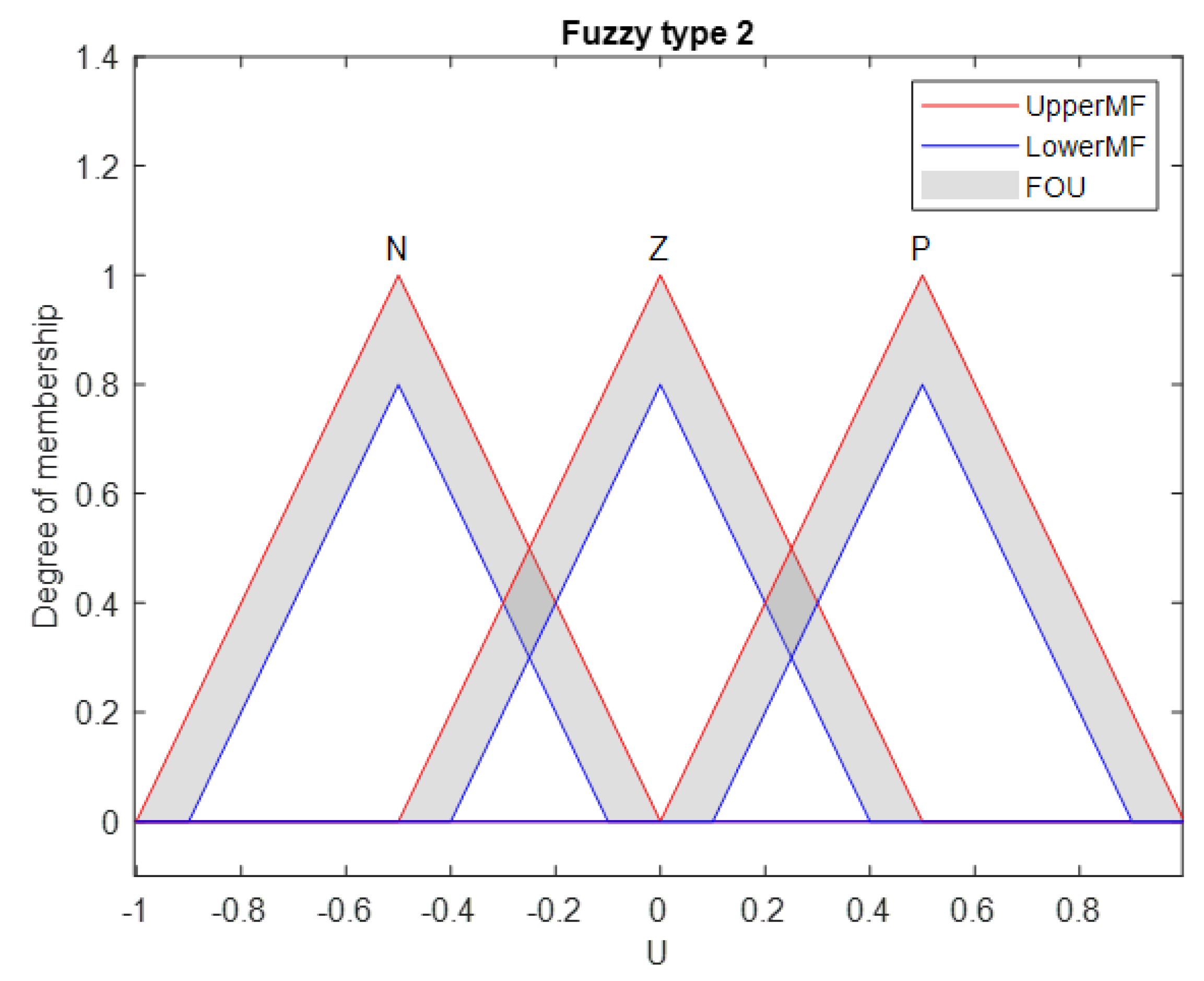
Figure 1 shows a triangular MF with its FOU, bounds with 20% scale factor and 20% lower lag in lower membership functions. Generally, an IT2FLS was reported in [31]. Figure 2 shows an IT2FLS, which is described in the following section. The structure of an IT2FLS is shown in Figure 3.

4.1. Fuzzifier Membership

The fuzzifier maps a real-valued variable into fuzzy sets. In this method, we simply use the singleton fuzzifier.

4.2. Fuzzy Rule

Expert knowledge will be considered in this part, which consists of a set of fuzzy IF-THEN rules. The jth rule in the IT2FLS is described as follows [31,39]:
R j :   If   x 1   is   F ˜ 1 j   and   x 2   is   F ˜ 2 j x n   is   F ˜ n j   then   y   is   G ˜ j ,   x i (   i = 1 , 2 , , n ) ,   j = 1 , 2 , , M
where M shows the number of rules; y is the output of the IT2FLS; and F ˜ i j and G ˜ j are the type-1 or type-2 antecedent and consequent sets, respectively.

4.3. Inference Engine

In IT2FLS, the inference engine combines rules and gives a mapping from input IT2FSs to output IT2FSs. By performing input and antecedent operations, the firing set is generally obtained as follows [31,39]:
F j ( X ) = i = 1 n μ F ˜ i j ( x i )
where product t-norm is assumed. More specifically, since we are concerned with IT2FSs here, the firing input sets were defined as follows [31,39]:
F j ( X ) = [ f _ j ( X ) , f ¯ j ( X ) ]
f _ j ( X ) = μ _ F ˜ 1 j μ _ F ˜ 2 j μ _ F ˜ n j
f ¯ j ( X ) = μ ¯ F ˜ 1 j μ ¯ F ˜ 2 j μ ¯ F ˜ n j
where f _ j ( X ) and f ¯ j ( X ) are the jth lower and upper MFs, respectively, and denotes t-norm.

4.4. Defuzzifier

To find the final crisp output value for the inference process, the type-2 fuzzy set output of the inference engine is first needed before defuzzification can be used to convert type-2 fuzzy sets into type-1 sets in a type reducer. Among the type reductions, center of sets (COS) is widely used because it can be computed more easily by the Karnik–Mendel (KM) iterative algorithm. Because we only used IT2FSs here, Y c o s is an interval set that is determined with its left-end point y l and right-end point y r . The COS type reducer can be expressed as [31,39]:
Y c o s   ( y l , y r ) = θ 1 θ M f 1 f M 1 / j = 1 M f j θ j j = 1 M f j
where f j F j ( X ) = [ f _ j ( X ) , f ¯ j ( X ) ] and θ j is the centroid of jth consequent set. Mendel and Karnik introduced two algorithms for calculating these two end points in [15], which are now known as the KM iterative algorithms. If we use a singleton fuzzifier, product inference engine and COS type reducer, y l and y r can be illustrated as follows [31,39]:
y l = j = 1 M f l j θ l j j = 1 M f l j = θ l T ξ l
where f l j is the point of jth consequent set, θ l = [ θ l 1 , , θ l M   ] T , ξ l j = f l j j = 1 M f l j , ξ l = [ ξ l 1 , , ξ l M   ] T and [31,39]:
y r = j = 1 M f r j θ r j j = 1 M f r j = θ r T ξ r
where θ r j and θ l j are the right-end and left-end point of jth consequent set, respectively,
θ r = [ θ r 1 , , θ r M   ] T ,   ξ r j = f r j j = 1 M f r j   and   ξ r = [ ξ l 1 , , ξ l M   ] T
Assuming θ l j are arranged in ascending order (i.e., θ l 1 θ l 2 θ l M ), y l is calculated using the KM algorithms. The same procedure is followed for calculating y r , and the defuzzified crisp output of the IT2FS is then calculated as follows [31,39]:
y r = y l + y r 2

5. SMC-Based Interval Type-2 Fuzzy System

5.1. T2FSMC Schemes

Appropriate design of each Γ and α fuzzy system to provide the required parameters of the fuzzy controller is essential [1]. In this section, the design approach of fuzzy type-1 (T1FSMC) and type-2 (T2FSMC) sliding mode control schemes for providing adaptive gains and slopes of the sliding surface so-called Γ and α fuzzy systems is explained. Due to suitable adaptation of fuzzy systems with optimization methods, this paper aimed to generate an optimal design of the Γ and α fuzzy systems using the optimization method of the studied approach. The recently designed concept of fuzzy systems established in [1] was considered for the development of the interval type-2 fuzzy systems for the purpose of this article.
The error and the time rate of the error are considered as input and output variables of the proposed Γ and α type-1 and type-2 fuzzy systems. The triangular membership functions were also employed for both fuzzy systems with uniform distribution of 50% overlap for type-1 and for the upper MFs of type-2 fuzzy systems. When selecting the range of output variables of type-1 and -2 fuzzy systems of Γ and α, achieving effective and appropriate tracking quality as well as preventing the saturation of the actuators are the main considerations to be taken into account. Both T1 and T2FSMCs were designed using the optimization method. The built-in MATLAB GA optimization algorithm through “tunefis” function was employed for this purpose. Twenty-five design variables serving as the “consequence” indices of the fuzzy rules were considered for the optimization of the rule base of the type-1 fuzzy systems. However, 10 more design variables of lower lags and scales of the lower output membership function of type-2 fuzzy systems were considered in the optimal design of the type-2 fuzzy systems. Repetition of the method indicated the adequacy of five generations. Additionally, the number of chromosomes in each population was considered equal to 150, and significant improvement was not observed while increasing the number of chromosomes. According to the proposed generalized design approach of fuzzy systems, the requirement of expert knowledge as a challenging aspect of fuzzy system design was eliminated, and the positiveness of the gains of sliding mode controller were guaranteed. The joint speeds were also limited to the predefined value to make the results more realistic. The design approach of type-1 and interval type-2 optimal fuzzy systems to provide each parameters of α or Γ were adopted according to the algorithm presented in [1]. It should be noted that despite the difference between these two proposed type-1 and interval type-2 fuzzy systems, the optimal design procedure is completely similar and based on the pseudo code given in [1]. In brief, the design procedure starts with the initial predefined proposed fuzzy system. Subsequently, during the repetitive calculation according to the principles of optimization algorithms, the structure of the desired fuzzy systems is designed by the optimizer with the appropriate change of the design variables. It should be mentioned that through cyclic calculation in each iteration, by selecting the design variables of the fuzzy system, the gains and coefficients of the sliding mode controller are calculated according to the theory stated in Section 3. Next, by applying the output of the controller to the robot arm, the collected response of the system is employed in the calculation of the cost value. The calculation continues until the design criteria is fulfilled.
It is noteworthy that the control action was limited to not exceeding the preset value in each actuator, i.e., τ a l l o w τ τ a l l o w   ( N . m ) . In addition, in order to ensure the results complied with realistic conditions, the joints’ speed was limited to prevent saturation, i.e., θ ˙ allow θ ˙ θ ˙ allow   ( deg / s ) . In calculation of the cost of operation, combination of the sum of square error and time rate of error along with the control action, i.e., C o s t = ( e T W e e ) + ( e ˙ T W e ˙ e ˙ ) + ( τ T W τ τ ) , is considered, in which W e , W e ˙ and W τ are scaling factors and τ is the vector of control effort.
The above procedure was used to design each of the type-1 and -2 fuzzy systems for α or Γ coefficients. The closed loop control schemes of the combined approaches of sliding mode control along with the type-1 and type-2 fuzzy systems to control the UR5 robot are explained in the following section.

5.2. T2FSMC with Adaptive Gains

The T2FSMC approach with adaptive gains provided by the so-called Γ fuzzy system and the corresponding controller scheme is depicted in Figure 4, where d represents the input disturbance. The output vector gain Γ of the related fuzzy system was employed in SMC to determine the factors of the switching part of the traditional SMC. As mentioned previously, errors were used as the input variables, and the Γ factor was considered as the output variable. The input memberships of the type-2 fuzzy system for Γ with 20% uncertainty in lower lag are shown in Figure 5.

5.3. T2FSMC with Tuned α Parameters

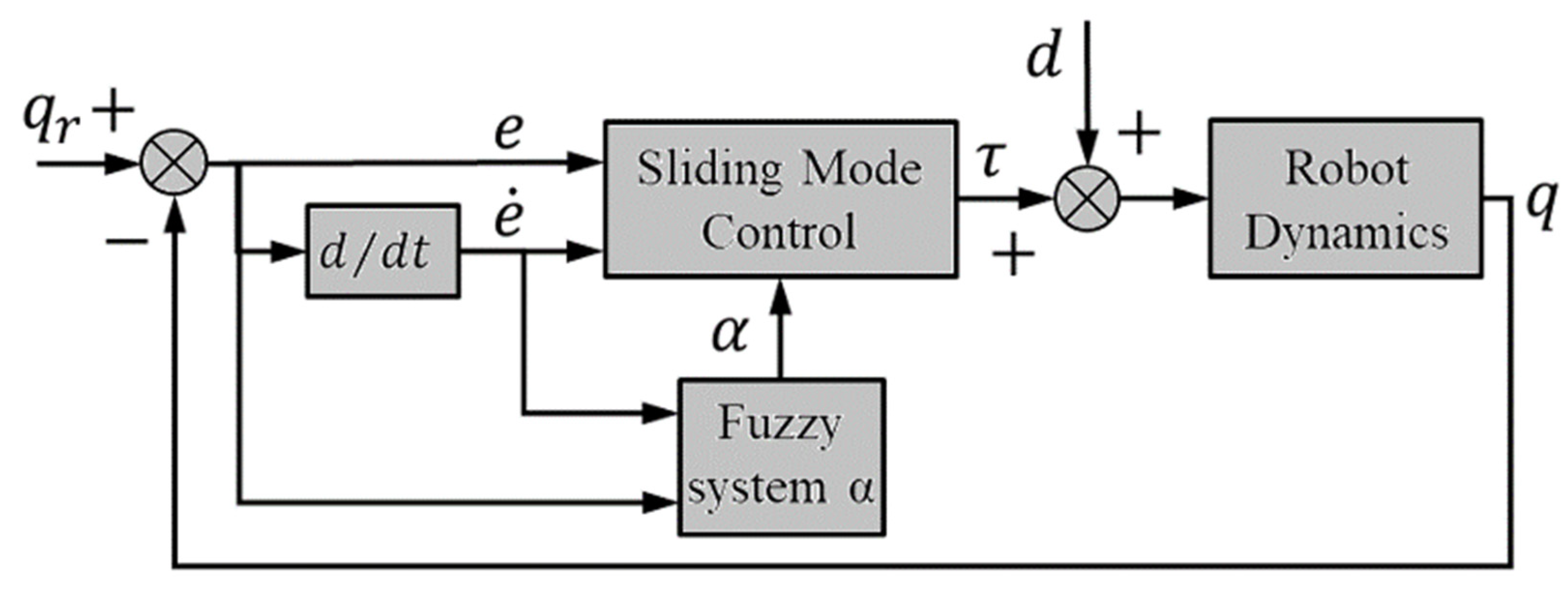
The closed loop control structure of the T2FSMC design with the α fuzzy system is depicted in Figure 6 [1]. As illustrated, the fuzzy system block received error and time rate of error, i.e., ( e , e ˙ ) , and delivered the corresponding α factor to the main controller. The input of this fuzzy system was same as the ones shown in Figure 5. As mentioned, α values through matrix G in Equation (21) were used to deliver the slope of the sliding surface.

5.4. T2FSMC with Tuned α and Γ Parameters

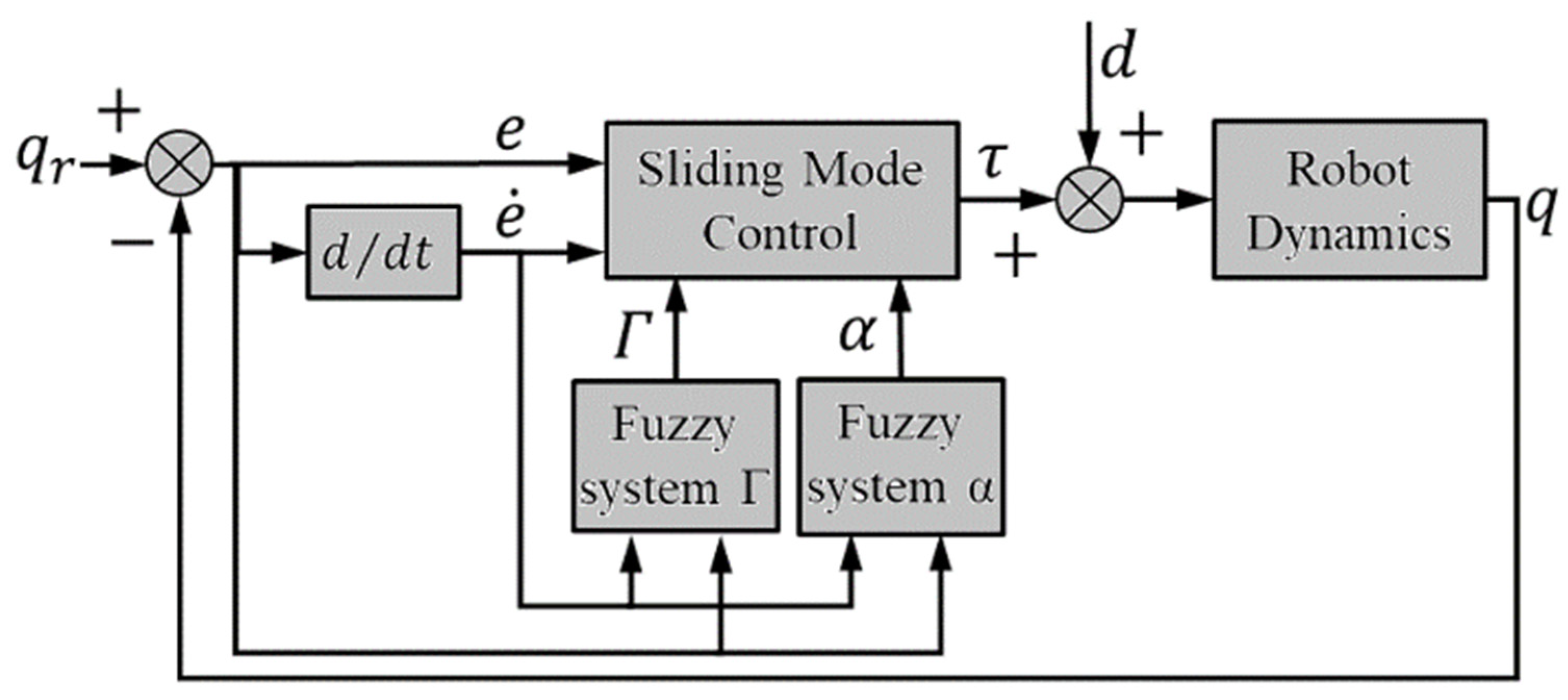
T2FSMC supplied with fuzzy systems of providing slopes of α and control gains of Γ was constructed using both fuzzy systems to provide the corresponding parameters of the controller. The closed loop control system is plotted in Figure 7. In the proposed controller, α and Γ had the inputs of ( e , e ˙ ) , and the corresponding outputs of α and Γ parameters were appropriately provided by the corresponding fuzzy systems.

5.5. Design of Type-2 Fuzzy Systems Assisting SMC

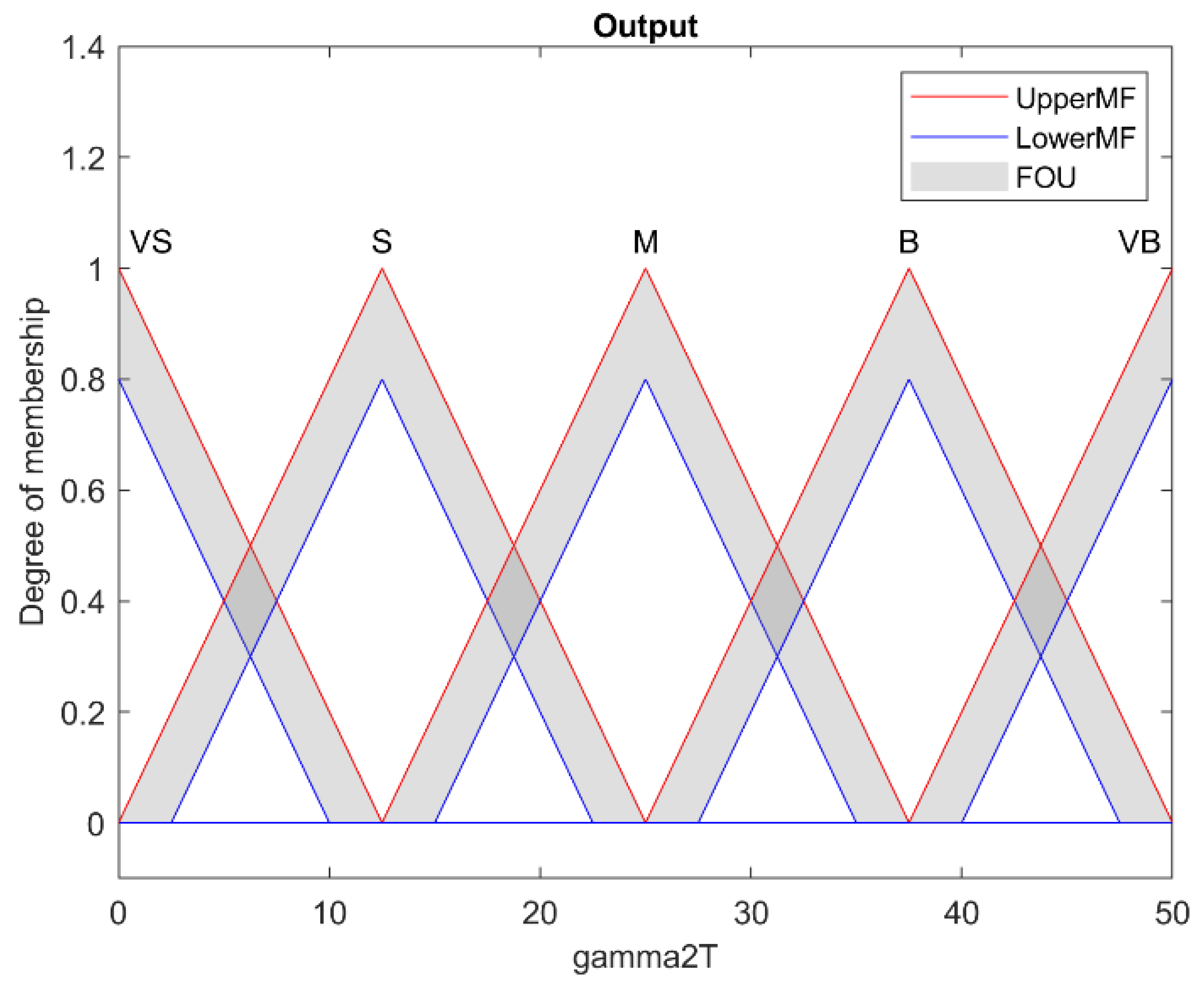
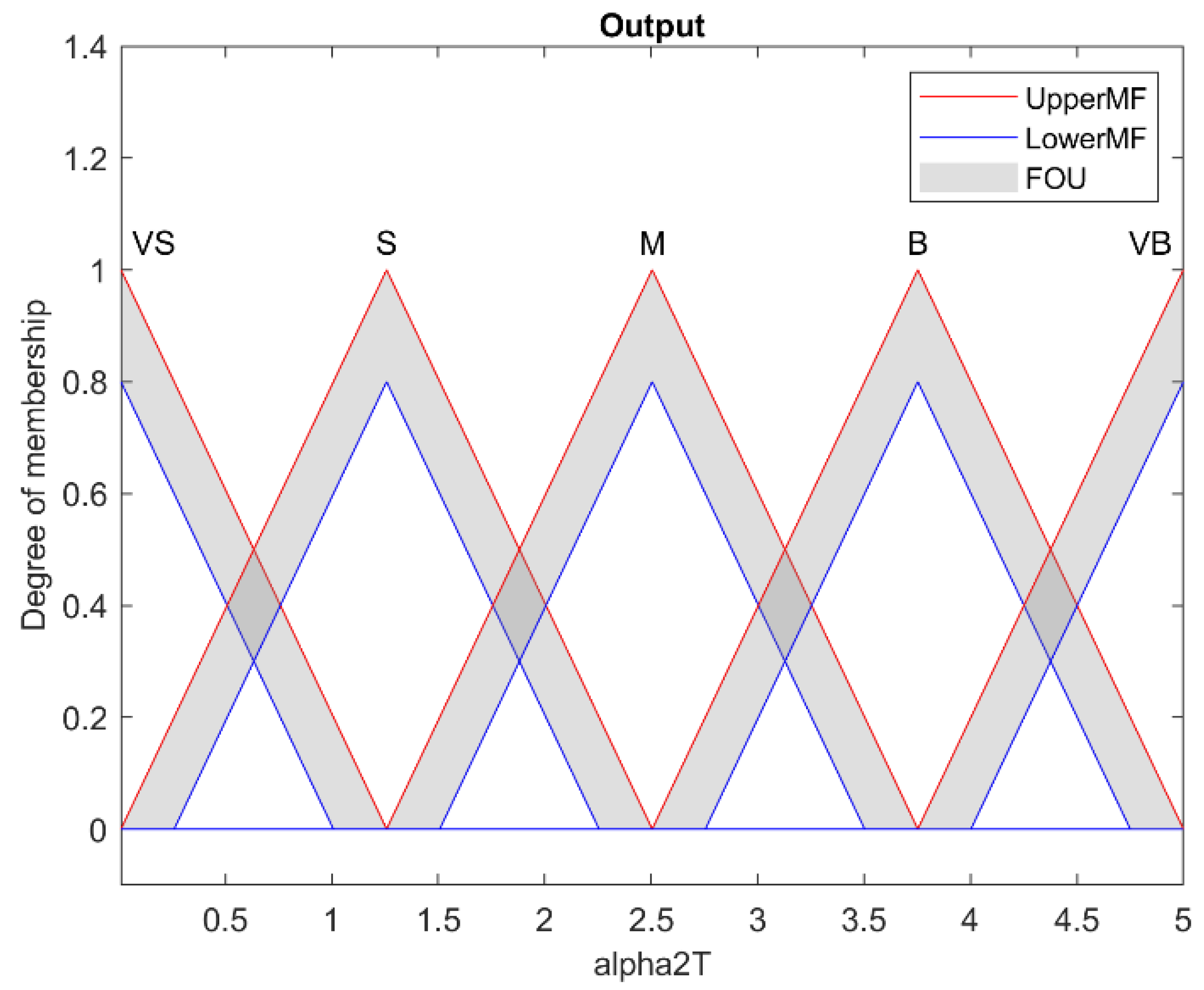
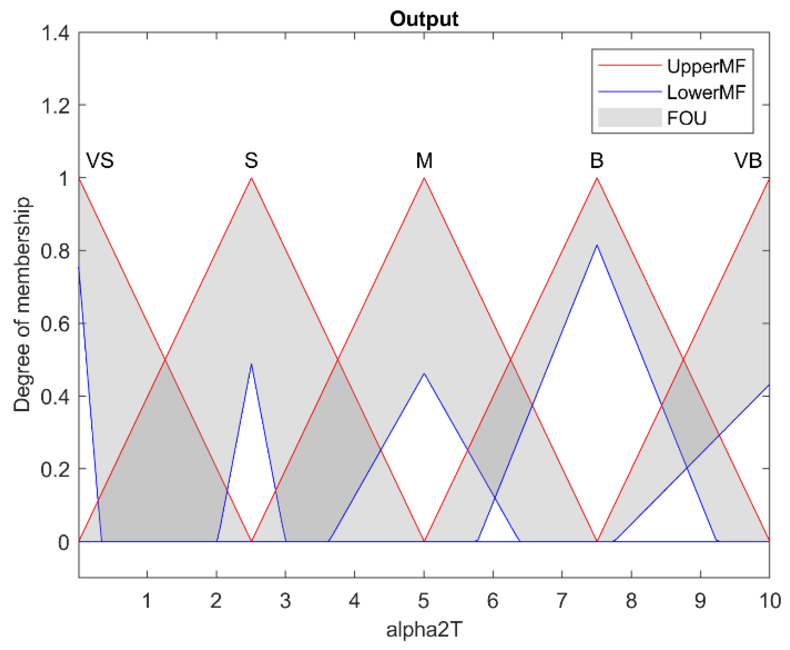
As mentioned above, the generalized designing of type-2 fuzzy systems to supply the required parameters of the optimal fuzzy sliding mode control scheme has been the main objective of this paper. The predefined and optimally designed output type-2 membership functions of α and Γ are plotted in Figure 8, Figure 9, Figure 10 and Figure 11, respectively. As shown, significant changes were observed in the scale and lower lag factors of T2MFs. The rule base of fuzzy systems as the main objectives of this article were optimally adjusted for both type-1 and type-2 fuzzy systems. It is noteworthy that in the optimization design phase of fuzzy systems, the effects of external input disturbances were not taken into account. The performance of fuzzy systems for providing control parameters in the event of robot exposure to input disturbances was then fairly evaluated.
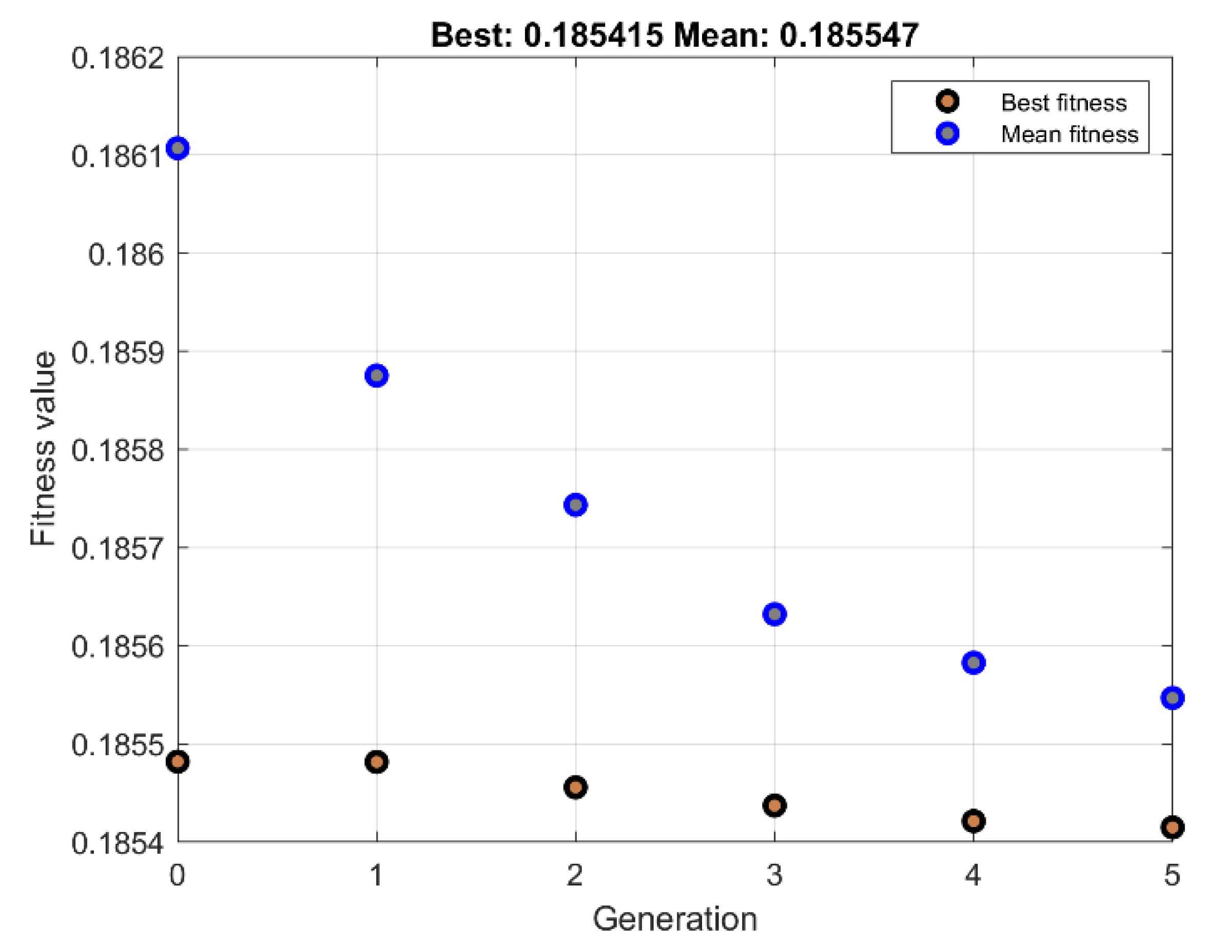
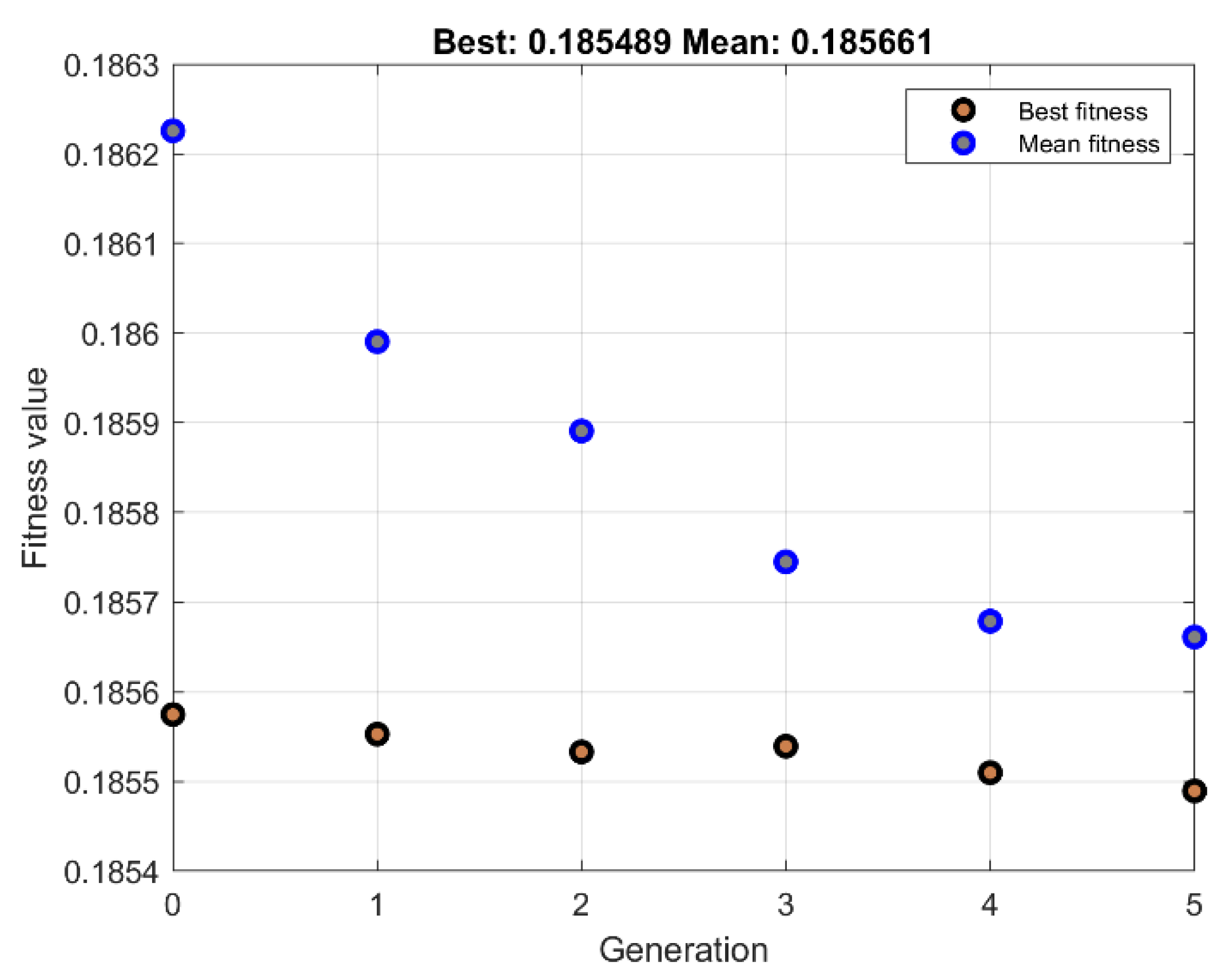
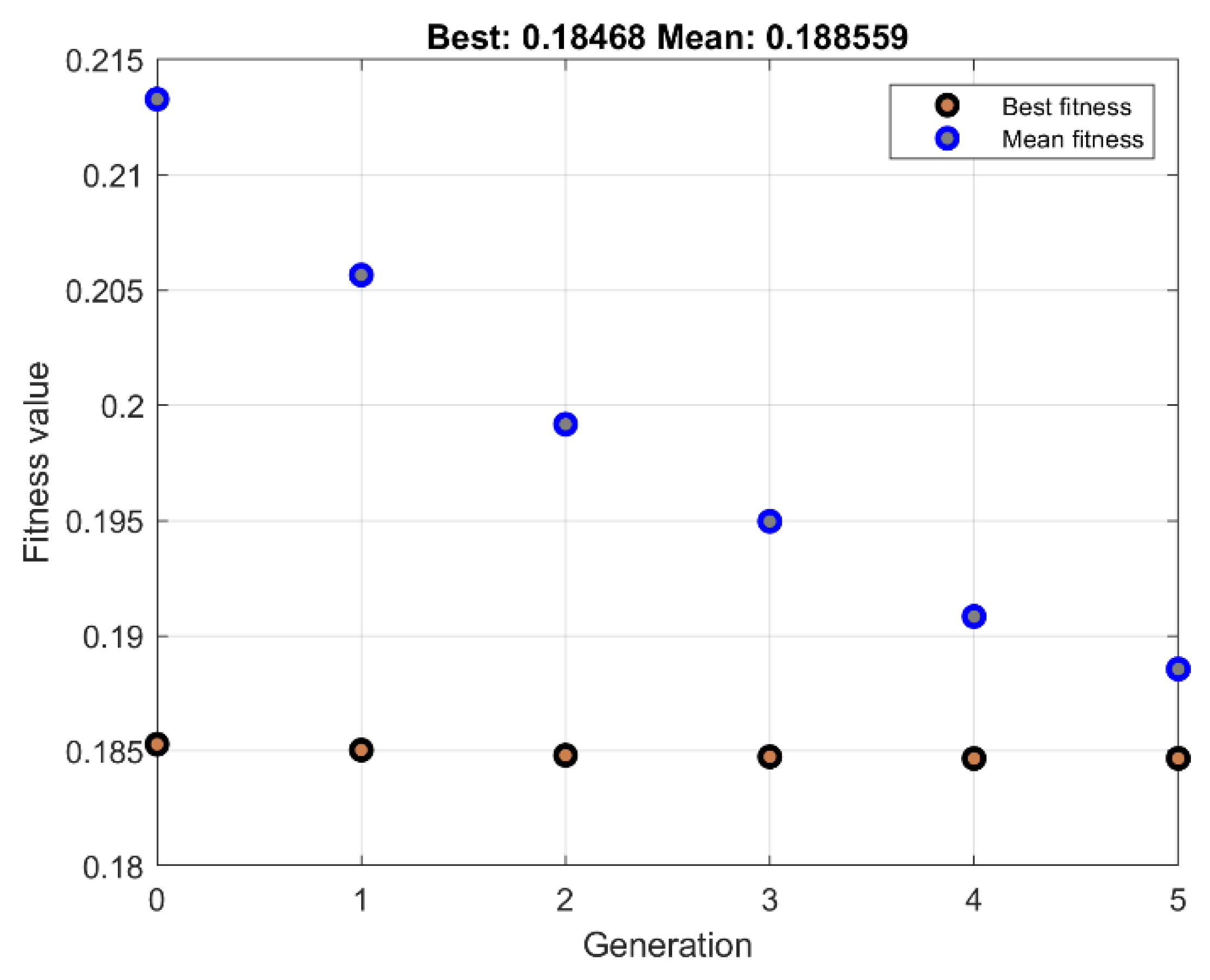
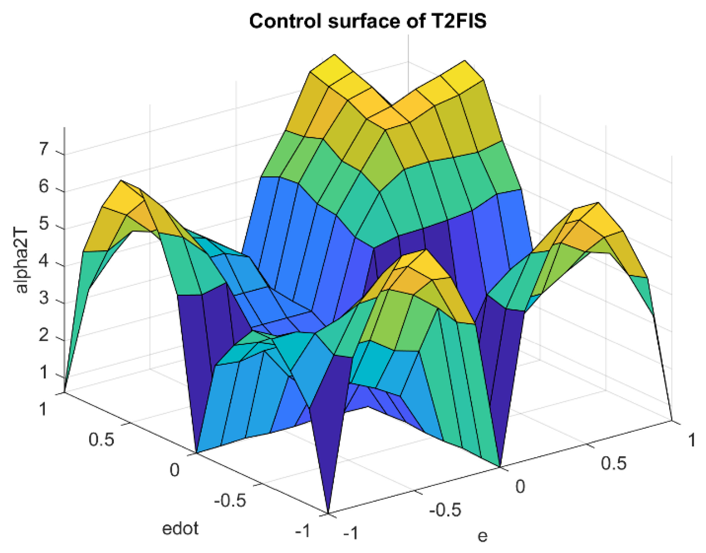
According to the optimization procedure, several outputs were available. In this regard, the trend of optimization quadratic cost function versus generation for type-1 and type-2 fuzzy systems are plotted in Figure 12, Figure 13, Figure 14 and Figure 15. According to the observations, successive repetition of five generations was sufficient to achieve proper convergence. Additionally, the same optimization performance was seen for type-1 and type-2 α and Γ fuzzy systems. Due to penalizing the control effort along with the joint’s positions and speeds tracking performance, the cost value was obviously not expected to exactly converge to zero. The adjusted fuzzy surfaces of the Γ and α type-1 and type-2 systems are illustrated in Figure 16, Figure 17, Figure 18 and Figure 19, respectively. The completely uneven fuzzy surfaces, which indicates complexity and entanglement of the fuzzy rules, confirm the difficulty of obtaining a reliable set of fuzzy rules relying on expert knowledge.
As expected, the optimization-based design procedure led to the optimally designed table of rules with minimal control efforts. The rule base of Γ and α type-1 and type-2 fuzzy systems are presented in Table 1, Table 2, Table 3 and Table 4, respectively. Each fuzzy system consisted of two inputs and one output with five triangular membership functions. By comparing the table of rules, one can see the clear difference between type-1 and type-2 fuzzy systems. Regardless of the initial presumed rule base, the optimal rules were obtained with the least number of repetitions. This result indicated the appropriate capability of the proposed approach in this paper for designing fuzzy systems without relying on expert knowledge, which is one of the main achievements of this research. Table 5 and Table 6 present the results of optimized values of scales and lower lags of type-2 membership functions of Γ and α systems. Considering predefined values, scattered changes were observed for the parameters after optimization. The values of these parameters are reflected in the diagrams of the optimal output membership functions depicted in Figure 8, Figure 9, Figure 10 and Figure 11.

6. Proficiency of the Proposed Hybrid Fuzzy SMCs

A set of computer simulations was performed to examine the operation of the proposed controllers. A 6DoF UR5 manipulator with the geometrical and physical parameters based on [36] was used as the challenging controlled plant. The desired joint trajectories were set as follows:
θ d 1 = ( π / 2 ) s i n ( t )   [ r a d ]
θ d 2 = 0.25 s i n ( 2 t )   [ r a d ]
θ d 3 = 0.25 c o s ( 2 t )   [ r a d ]
θ d 4 = π c o s ( 2 t )   [ r a d ]
θ d 5 = c o s ( 2 t )   [ r a d ]
θ d 6 = c o s ( 3 t )   [ r a d ]
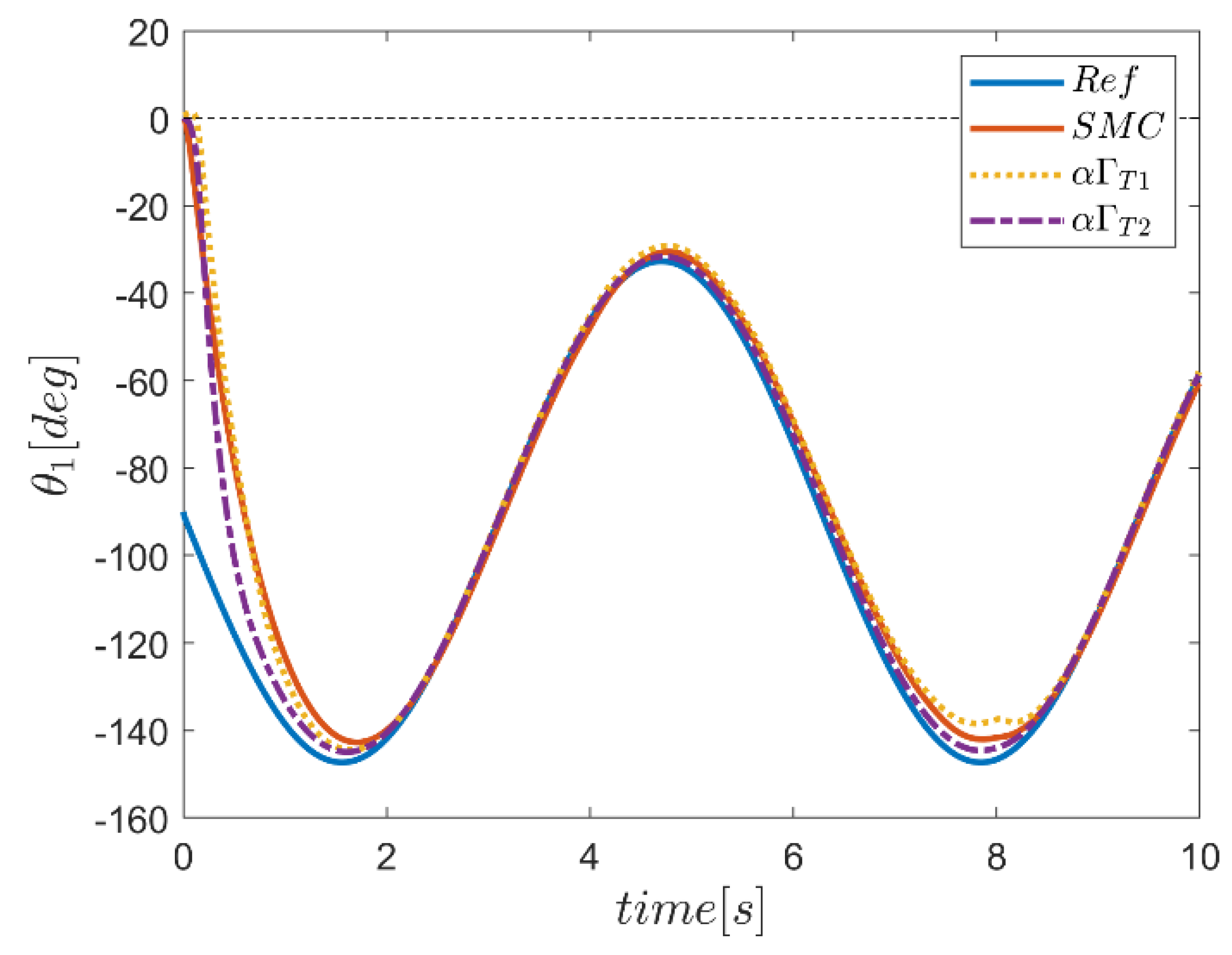
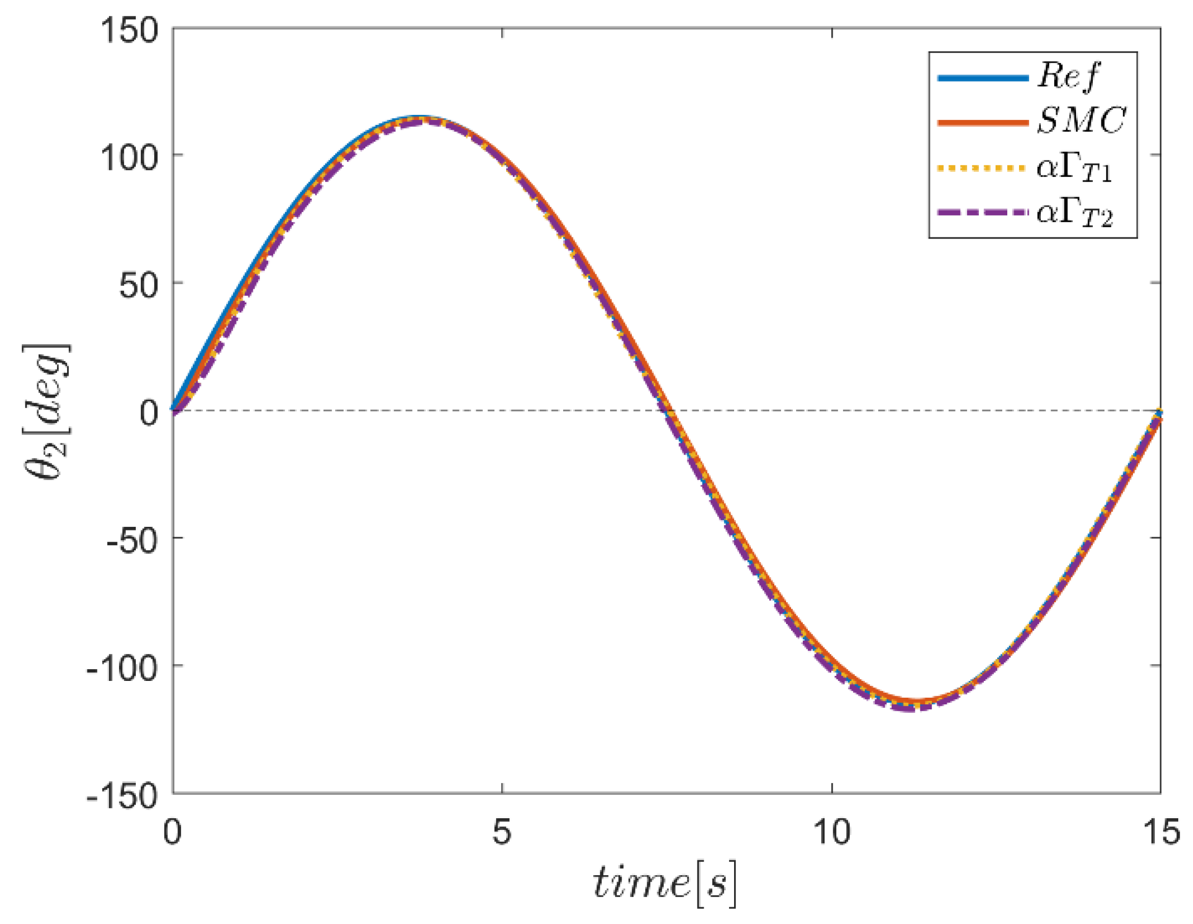
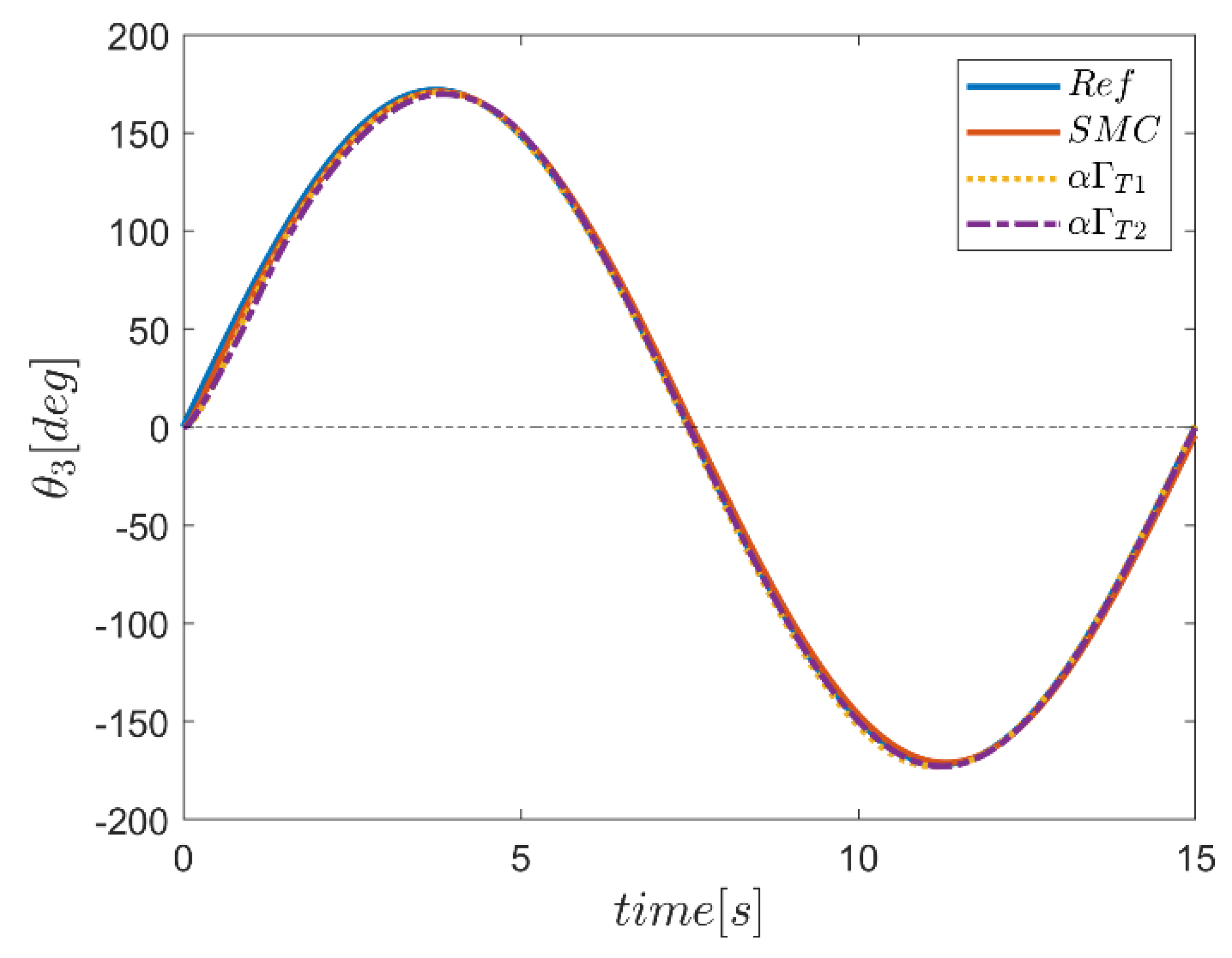
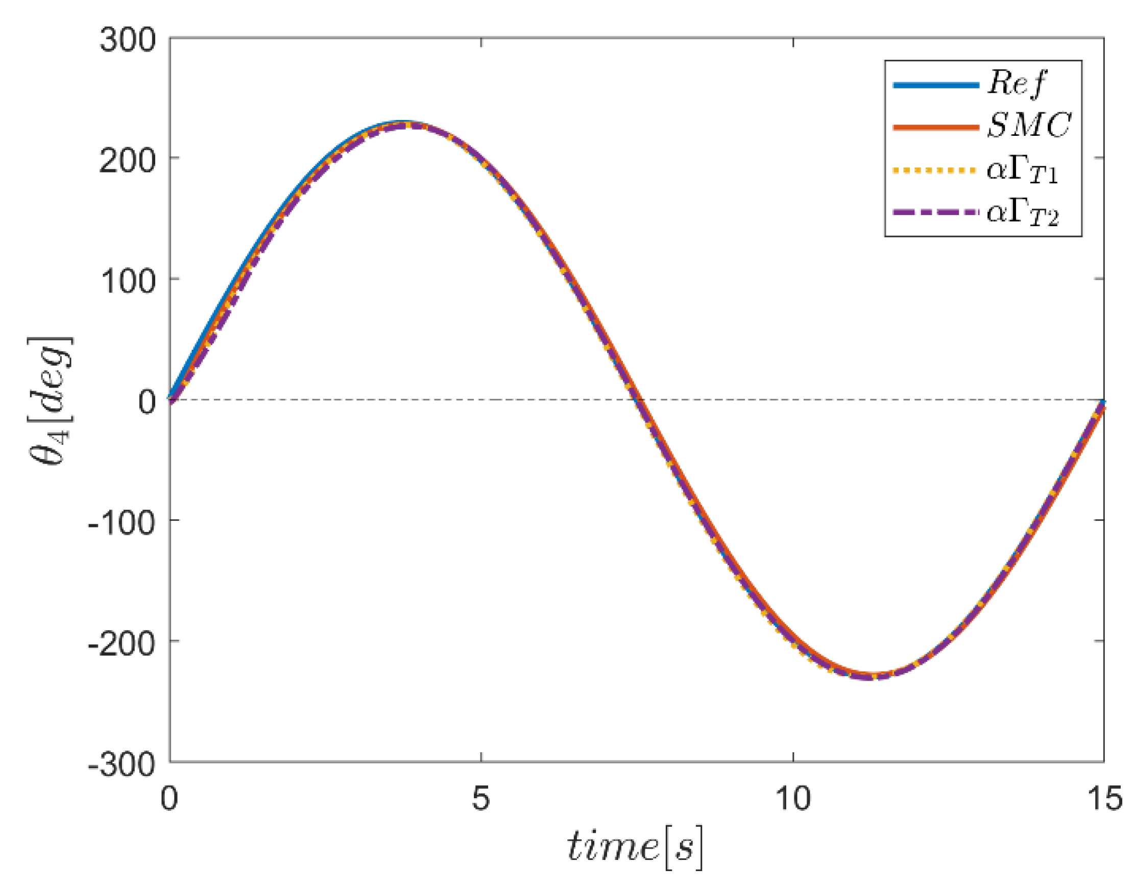
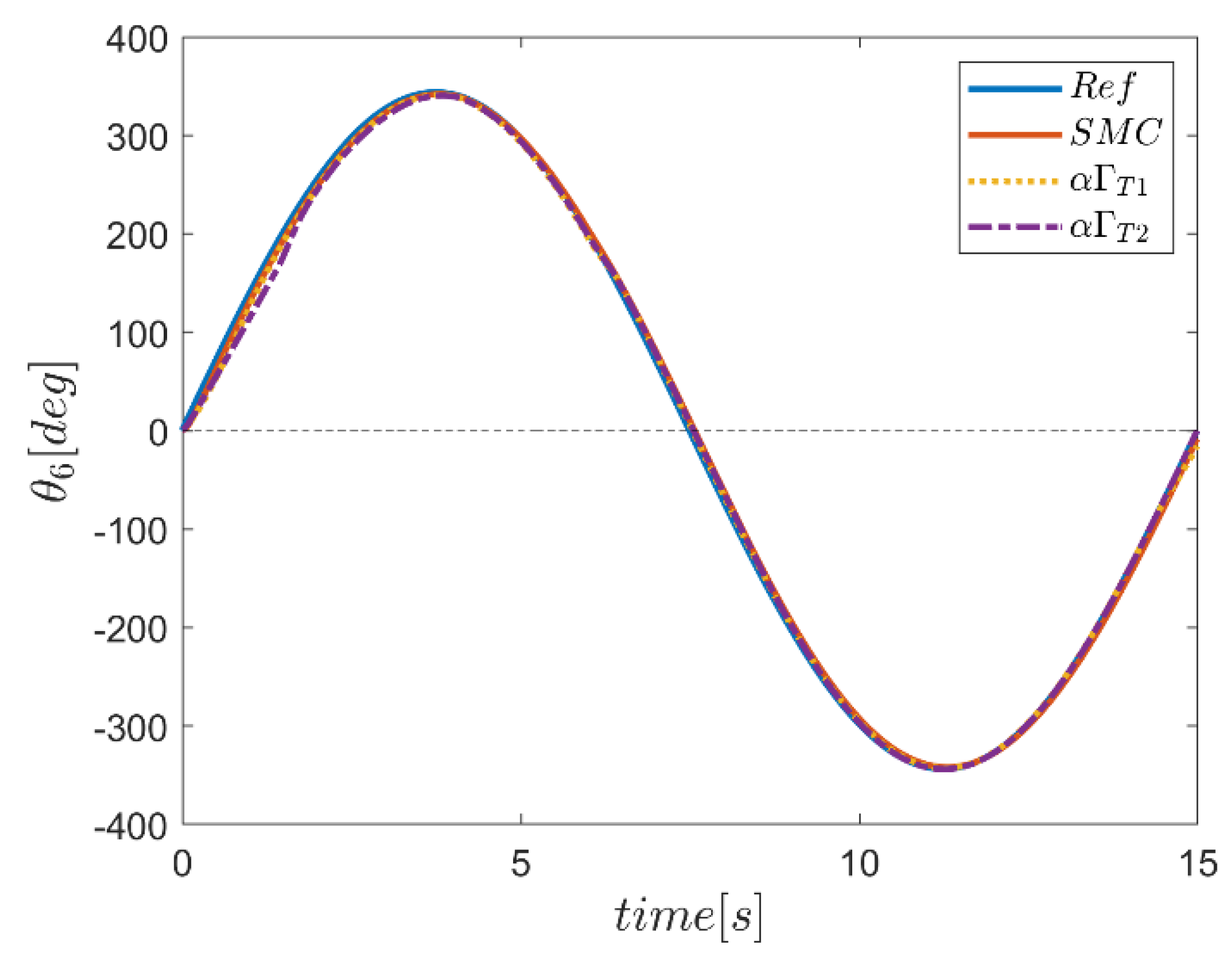
To illustrate the effectiveness of the presented control methods in eliminating the disturbances, the robot was assumed to be posed to an input d ( t ) , acting on the three revolute joints of one, two and six, as plotted in Figure 20. The comparative study of the performance of the proposed control schemes using type-2 fuzzy systems against the type-1 fuzzy systems as well as the conventional SMC was conducted. The conventional SMC with moderate constant coefficients of α ( = [ 2 , 2 , 2 , 2 , 2 , 2 ] ) and Γ ( = [ 20 , 20 , 20 , 20 , 20 , 20 ] ) was considered for this study. In order to make the simulation results more realistic, the input control torques and rotating joint speeds were limited to the range of [ 150 , 150 , 120 , 50 , 3010 ] τ [ 150 , 150 , 120 , 50 , 3010 ]   ( N . m ) and 360 θ ˙ 360   ( deg / s ) , respectively. The comprehensive output results of the simulations are plotted in Figure 21, Figure 22, Figure 23, Figure 24, Figure 25, Figure 26, Figure 27, Figure 28, Figure 29, Figure 30, Figure 31, Figure 32, Figure 33, Figure 34, Figure 35, Figure 36, Figure 37, Figure 38, Figure 39, Figure 40, Figure 41, Figure 42, Figure 43, Figure 44, Figure 45, Figure 46, Figure 47, Figure 48, Figure 49, Figure 50, Figure 51, Figure 52, Figure 53, Figure 54, Figure 55, Figure 56, Figure 57, Figure 58, Figure 59, Figure 60, Figure 61, Figure 62, Figure 63 and Figure 64. To distinguish between the type-1 and type-2 fuzzy systems, the subscripts of “T1” and “T2” were also considered in the annotation, respectively.
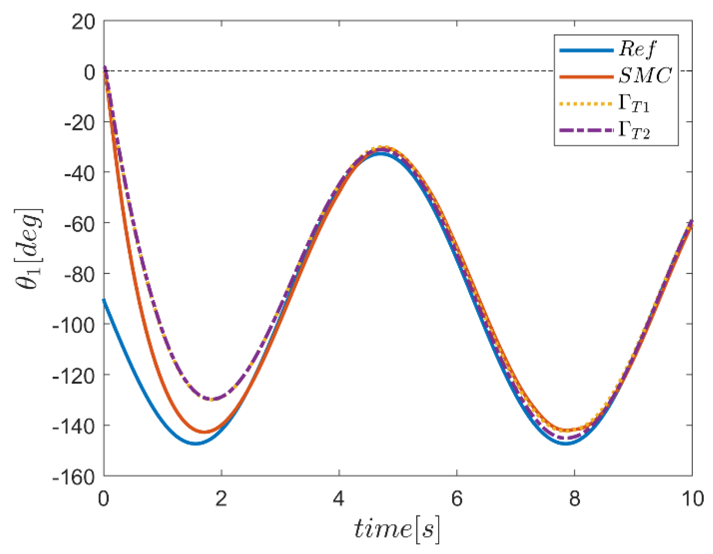
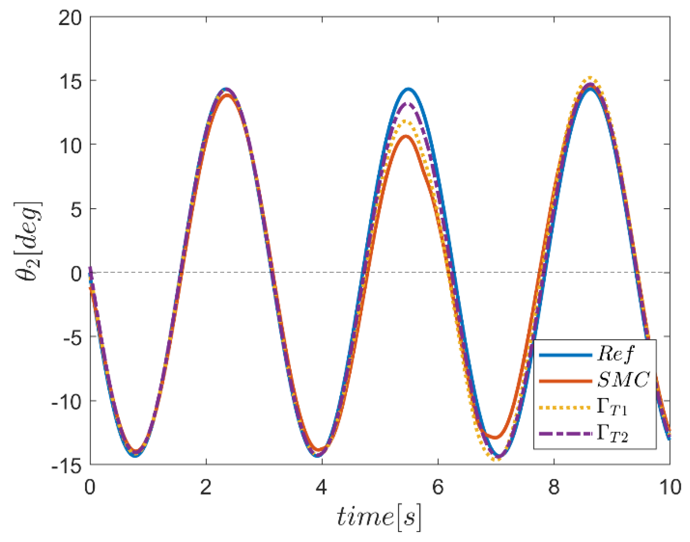
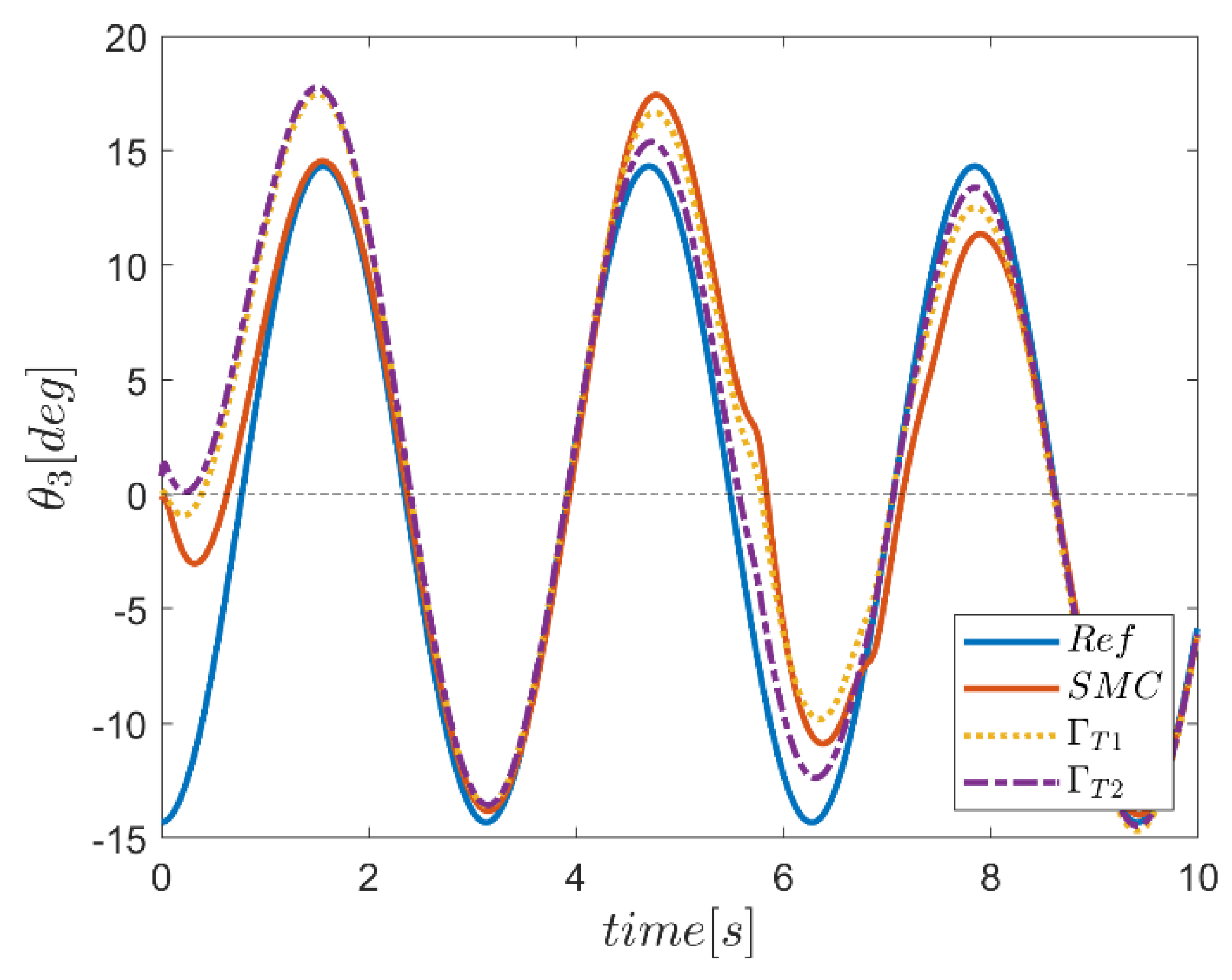
The result of desired trajectory tracking of joints using both type-1 and type-2 Γ FSMC and conventional SMC are plotted in Figure 21, Figure 22, Figure 23, Figure 24, Figure 25 and Figure 26. In the first, third, fourth, fifth and sixth channels, where the initial position of the robot was different from the reference input position, we witnessed path tracking errors. It should be noted that the performance of the SMC method was better than the two fuzzy Γ methods in the transient region. However, the quality of tracking methods based on Γ fuzzy systems continued to show better control quality. This quality of tracking reinforcement, especially in the period when the robot was exposed to external undesired inputs in three joints of first, second and sixth, clearly showed the proper performance of fuzzy control systems.
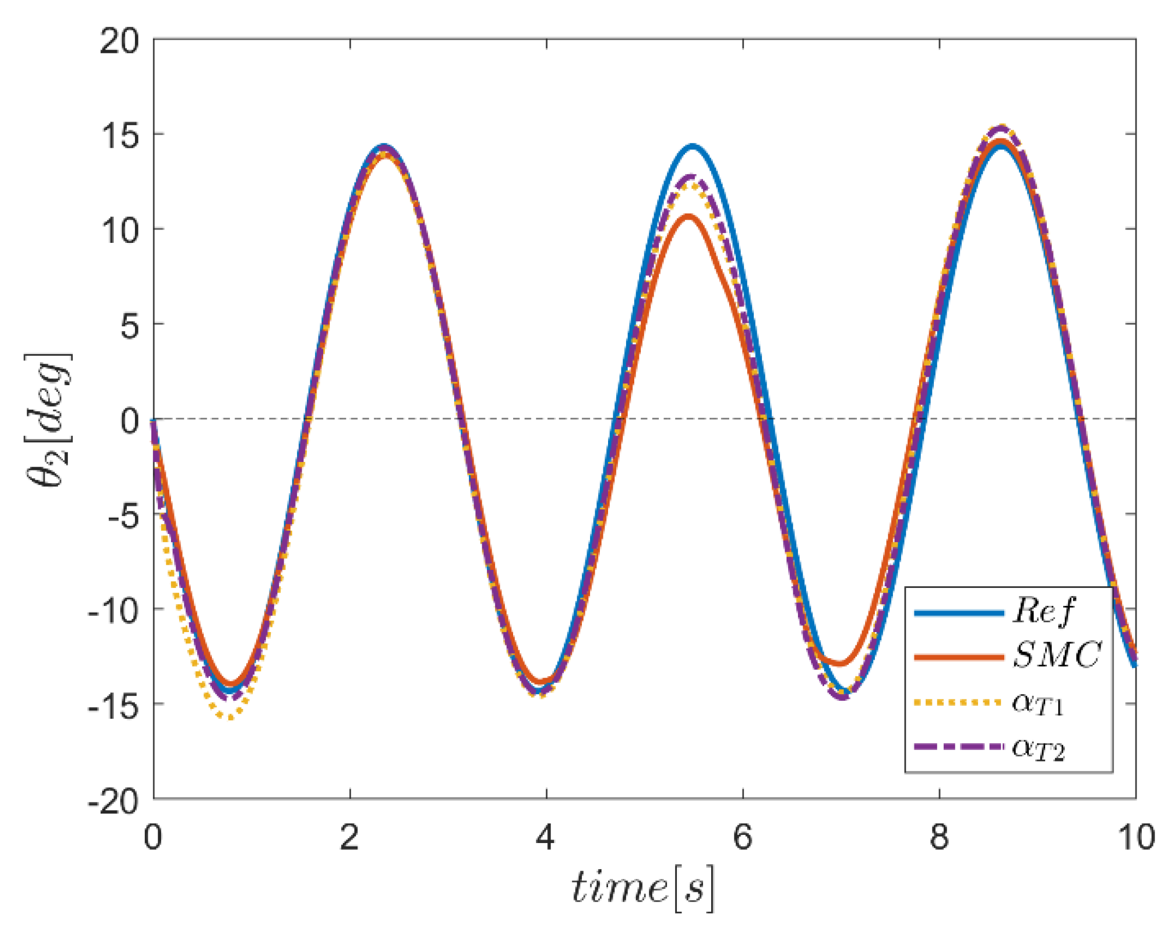
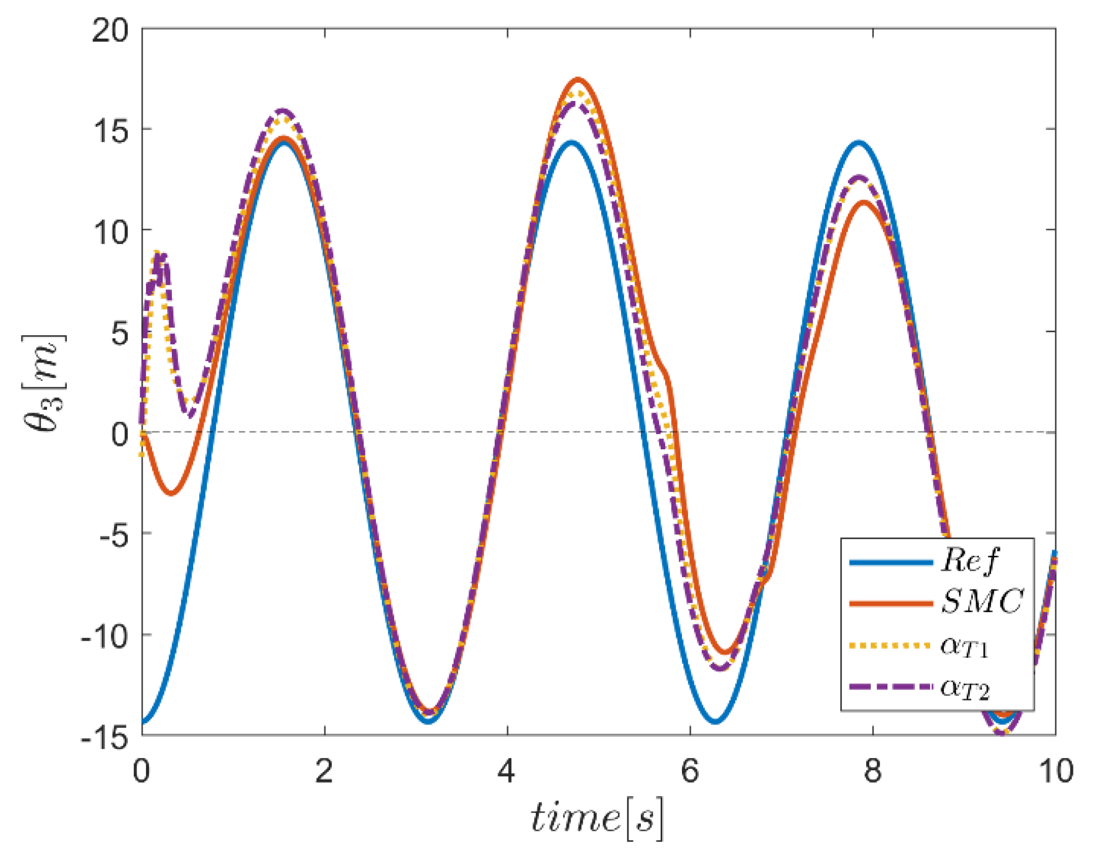
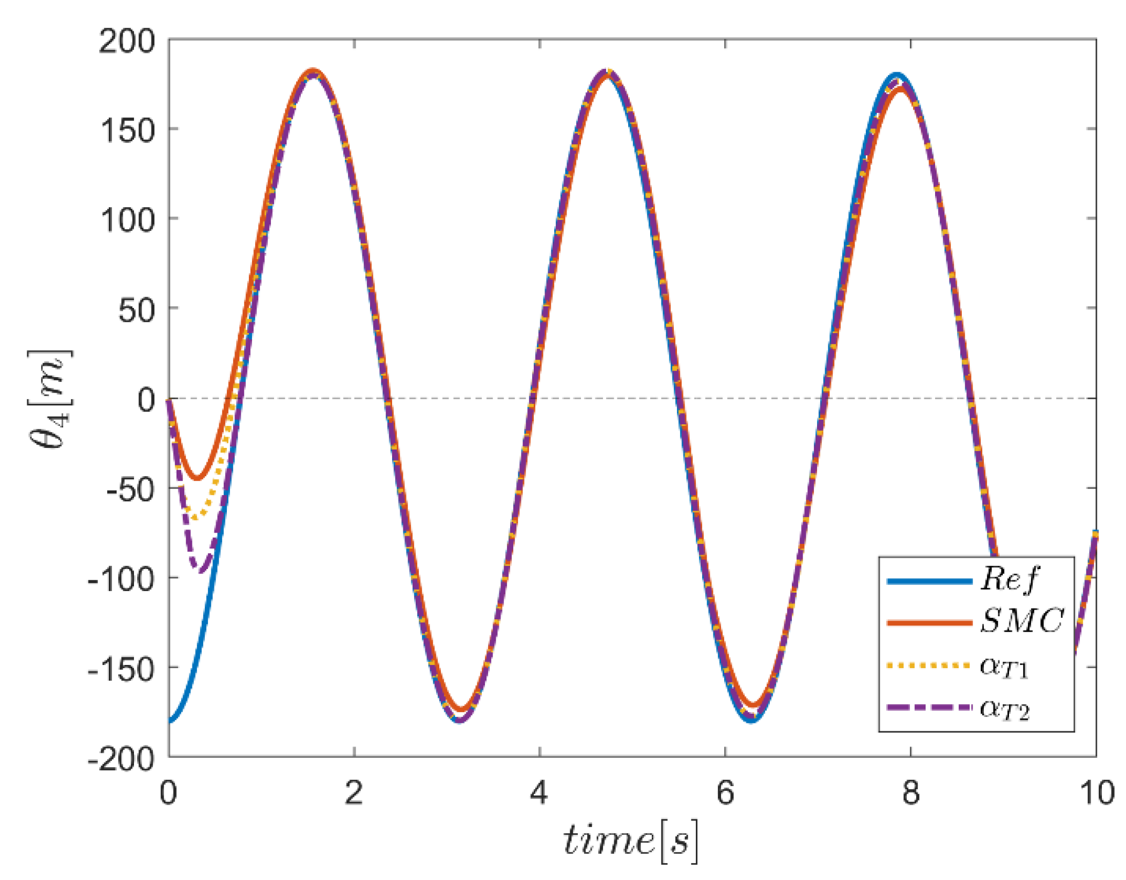
The result of reference path tracking of joints using both type-1 and type-2 α FSMC and conventional SMC are depicted in Figure 27, Figure 28, Figure 29, Figure 30, Figure 31 and Figure 32. Investigating the simulation results using fuzzy controllers compared with conventional sliding mode control systems revealed higher effectiveness of control approaches based on fuzzy systems both in the transient region and in areas where the robot was exposed to undesired input disturbances. Between the two types of α fuzzy systems, in most joints, the fuzzy type-2 controller showed more robust behavior than the type-1 fuzzy system. However, especially in the third channel, the tracking error due to the effect of input disturbance was observed in the time interval of the input effect. However, it can generally be concluded that the type-2 fuzzy control approach had a superior performance than the type-1 approach in this case. The trajectory performance of the type-1 and type-2 FSMCs, which used a combination of Γ and α fuzzy systems to provide parameters along with the conventional SMC, are plotted in Figure 33, Figure 34, Figure 35, Figure 36, Figure 37 and Figure 38. According to the simulation results in all joints, a superior performance quality of the αΓ type-2 fuzzy system was observed in comparison with the performance of the αΓ type-1 fuzzy system as well as the conventional SMC. Although the conventional sliding mode control system showed acceptable performance, the tracking quality of this controller was somewhat deteriorated, especially in the range of the external input effect in the third channel. To summarize the performance comparison of the controllers, the fuzzy type-2 αΓ sliding mode controller showed superior performance compared with the other two methods by almost completely eliminating the effect of annoying inputs in the transient region.
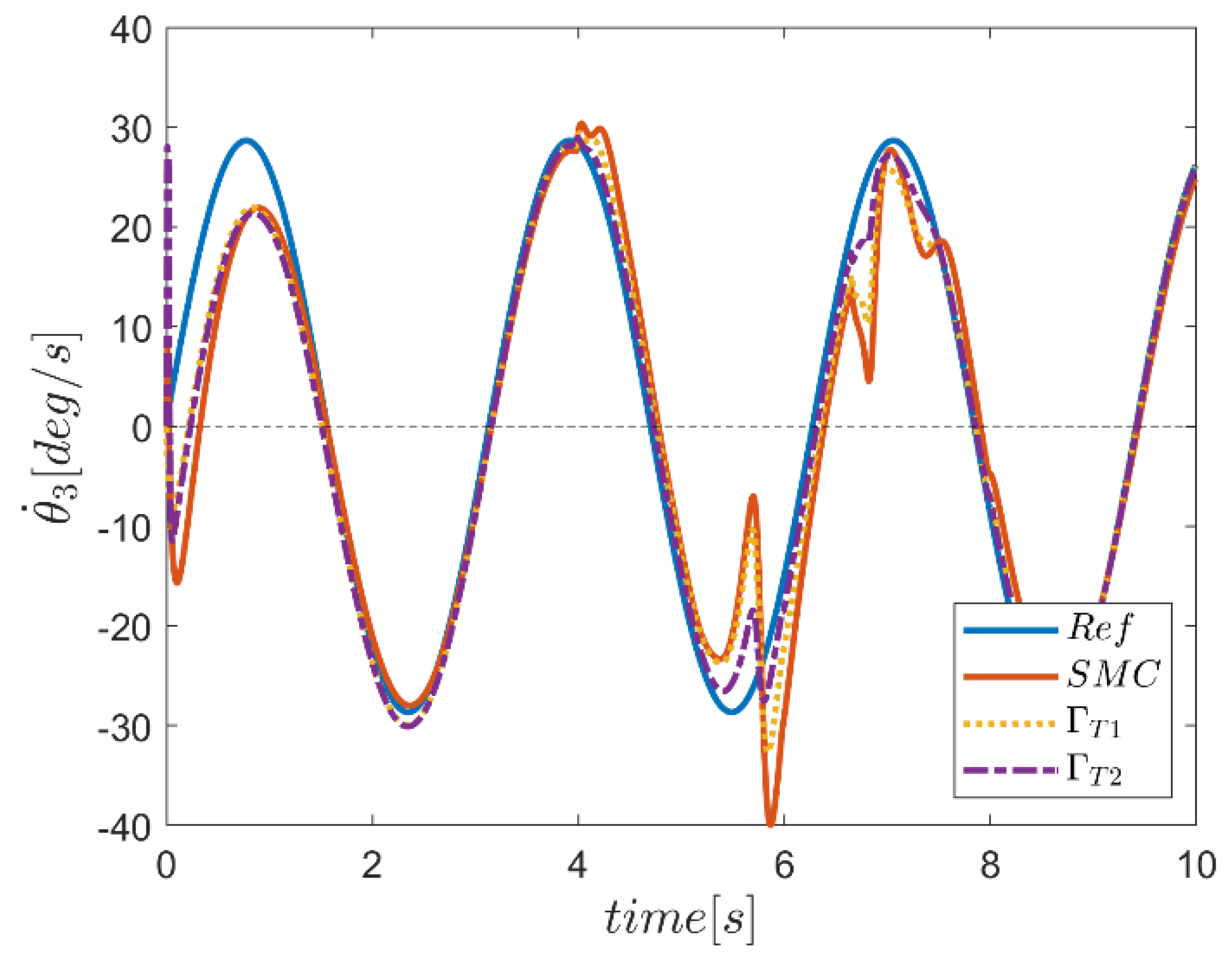
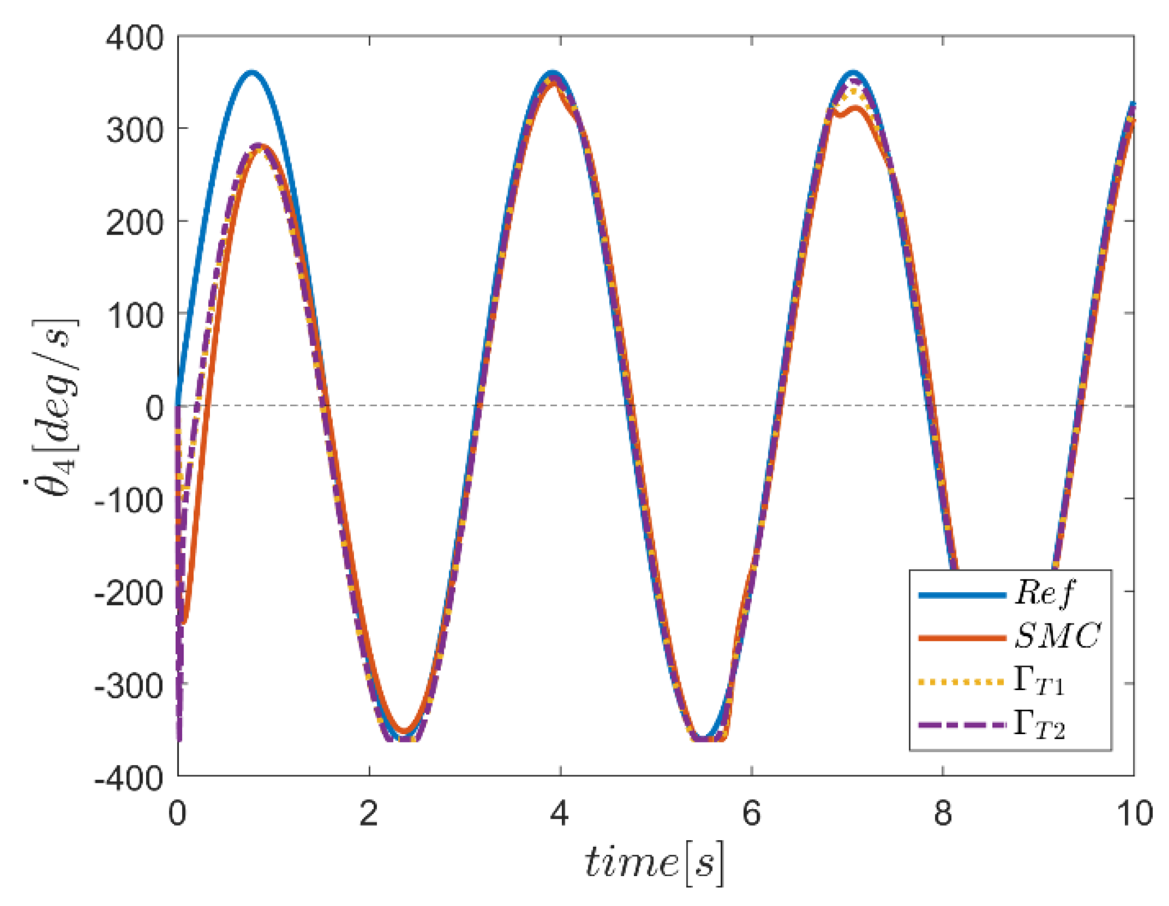
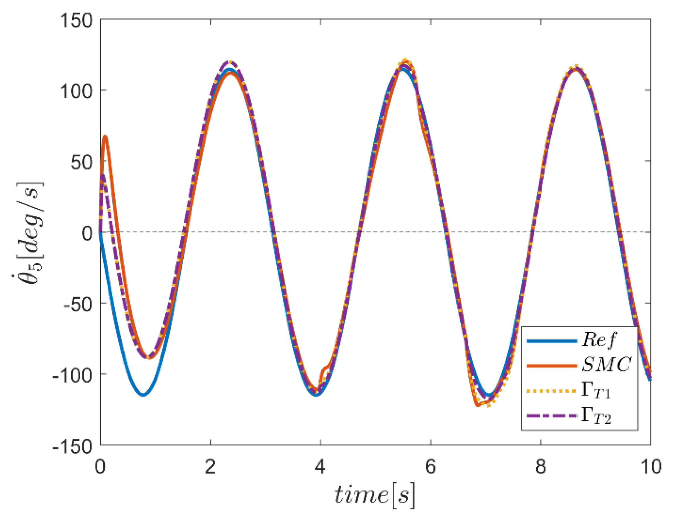
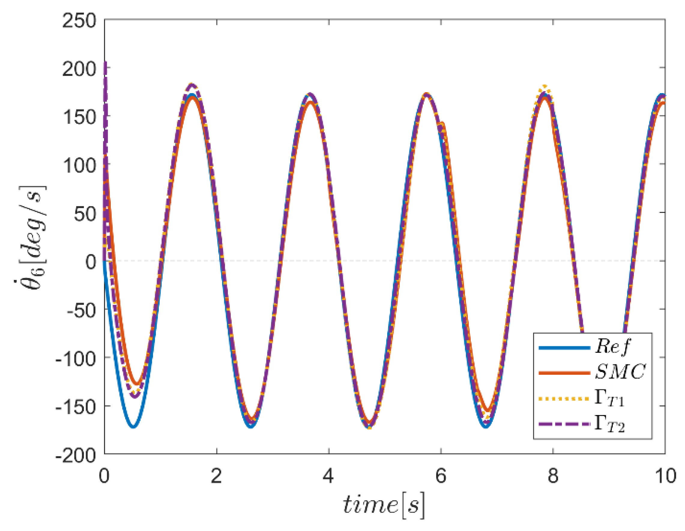
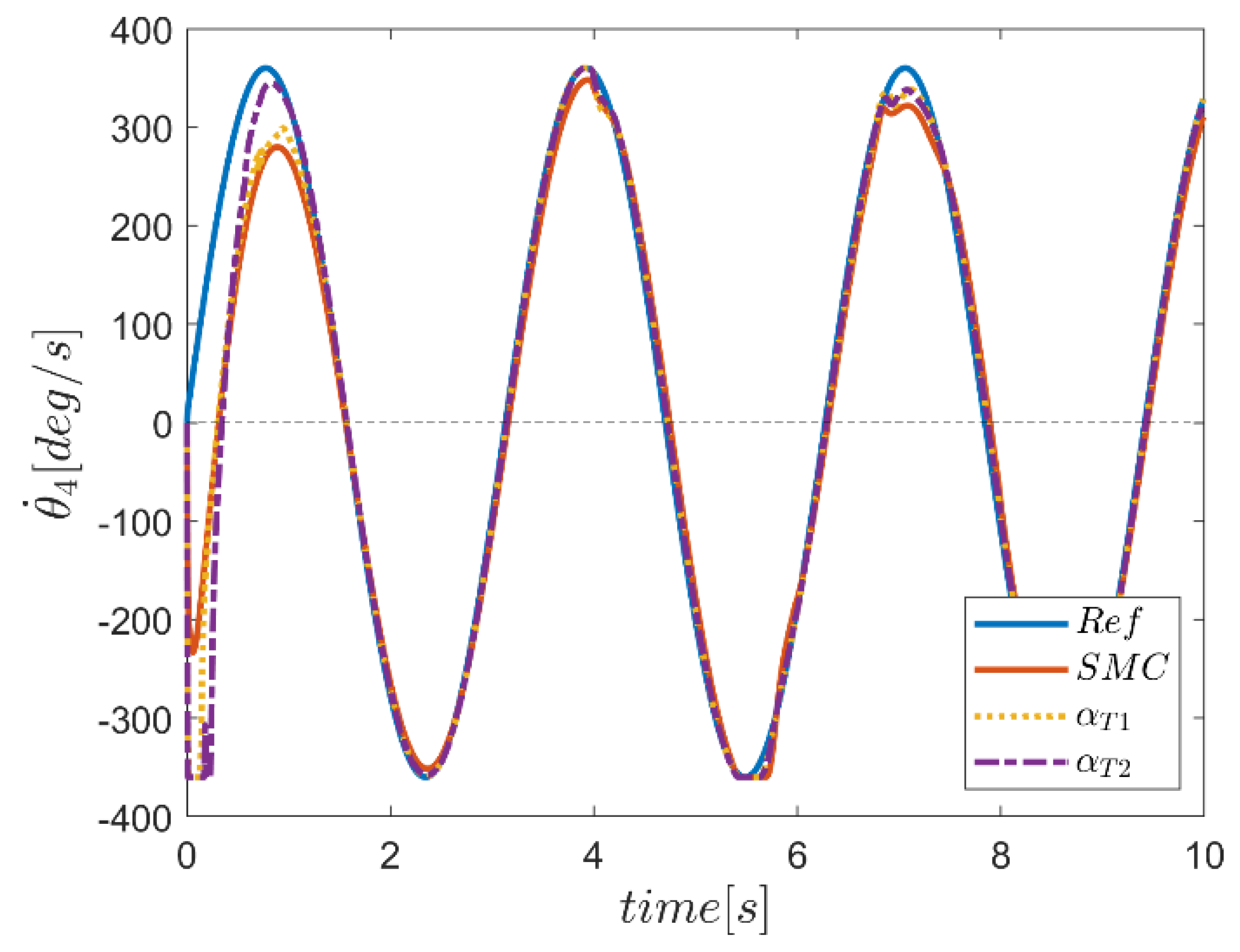
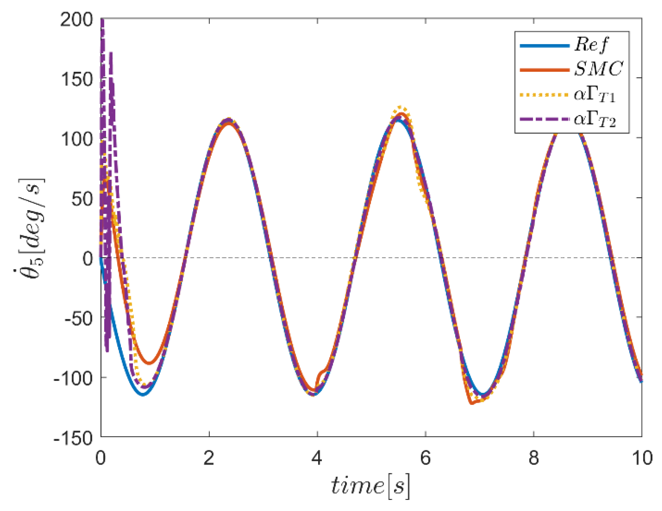
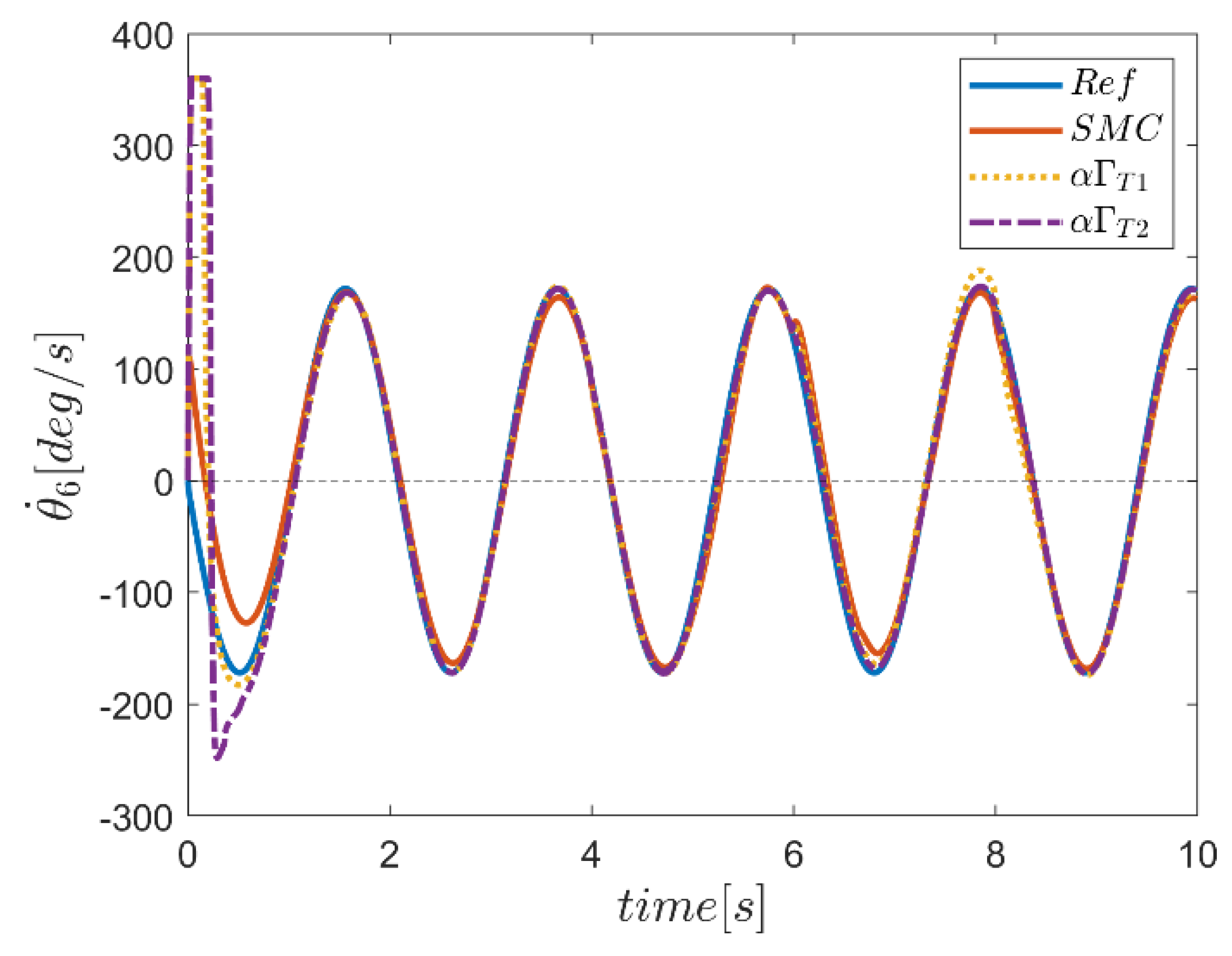
Regarding control of robot manipulators, tracking reference speeds is also essential. Due to the harmonic reference motion for the joints, the reference speed in the joints is also harmonic. To evaluate the performance of all three controllers in tracking the reference speed inputs, tracking curves of the Γ fuzzy controller system along with conventional sliding mode controller are plotted in curves 39 to 44. Regarding the performance of the controllers, in channel one, we see the unsatisfactory performance of all the controllers in the transient region. In other channels, however, the behavior of all three controllers in the transient region was relatively acceptable. Considering the performance of the controllers against the effect of disturbance inputs, the performance of the controllers based on fuzzy systems was specifically more robust in joint two. However, in the third joint, the disturbance input effects seemed more obvious. In this joint, the performance of the type-2 Γ fuzzy controller was much more robust than other methods. In other joints, the performance of fuzzy systems was much better, and the system was fully resistant against unwanted inputs. Overall, the result of the type-2 Γ fuzzy system approach was superior to the other methods.
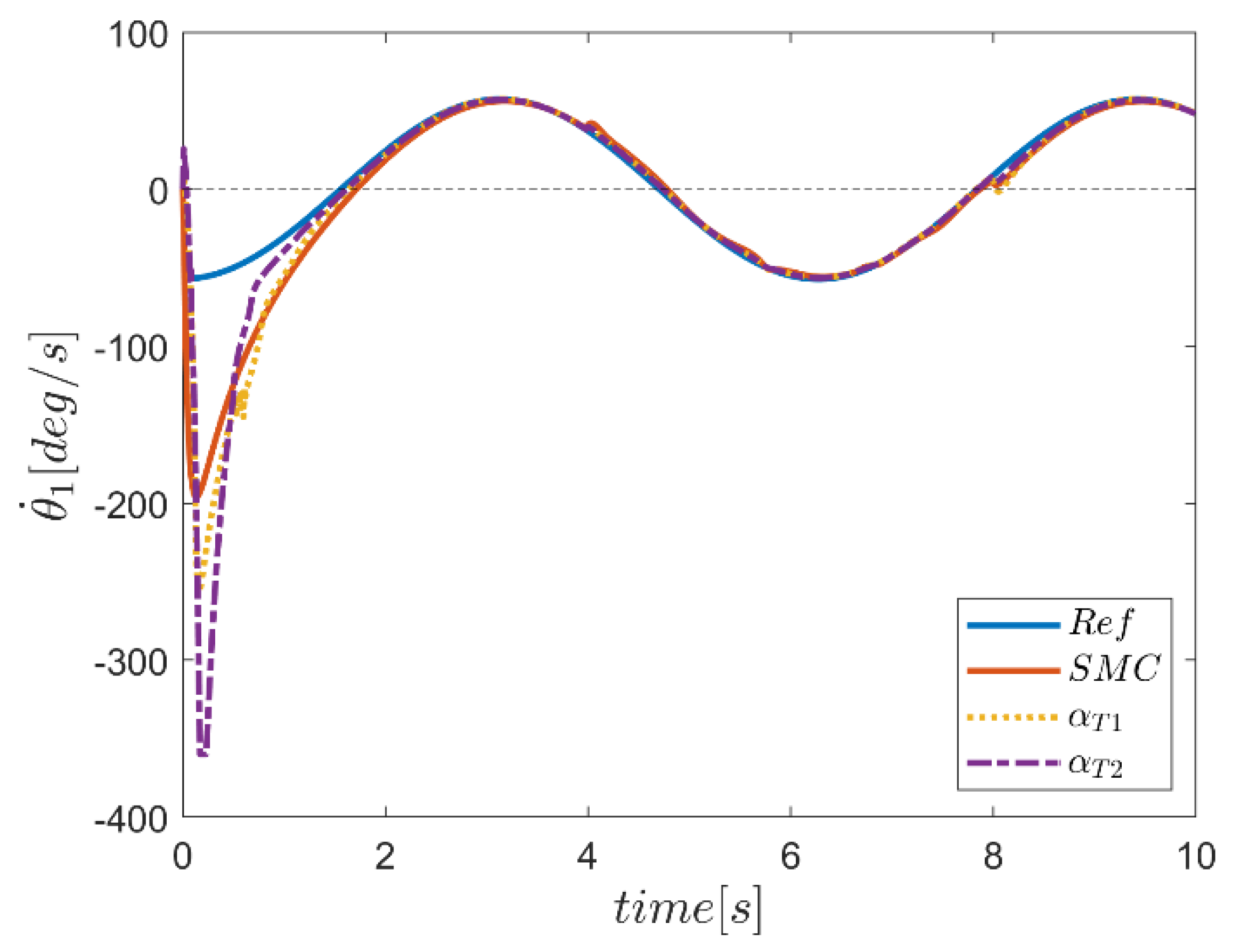
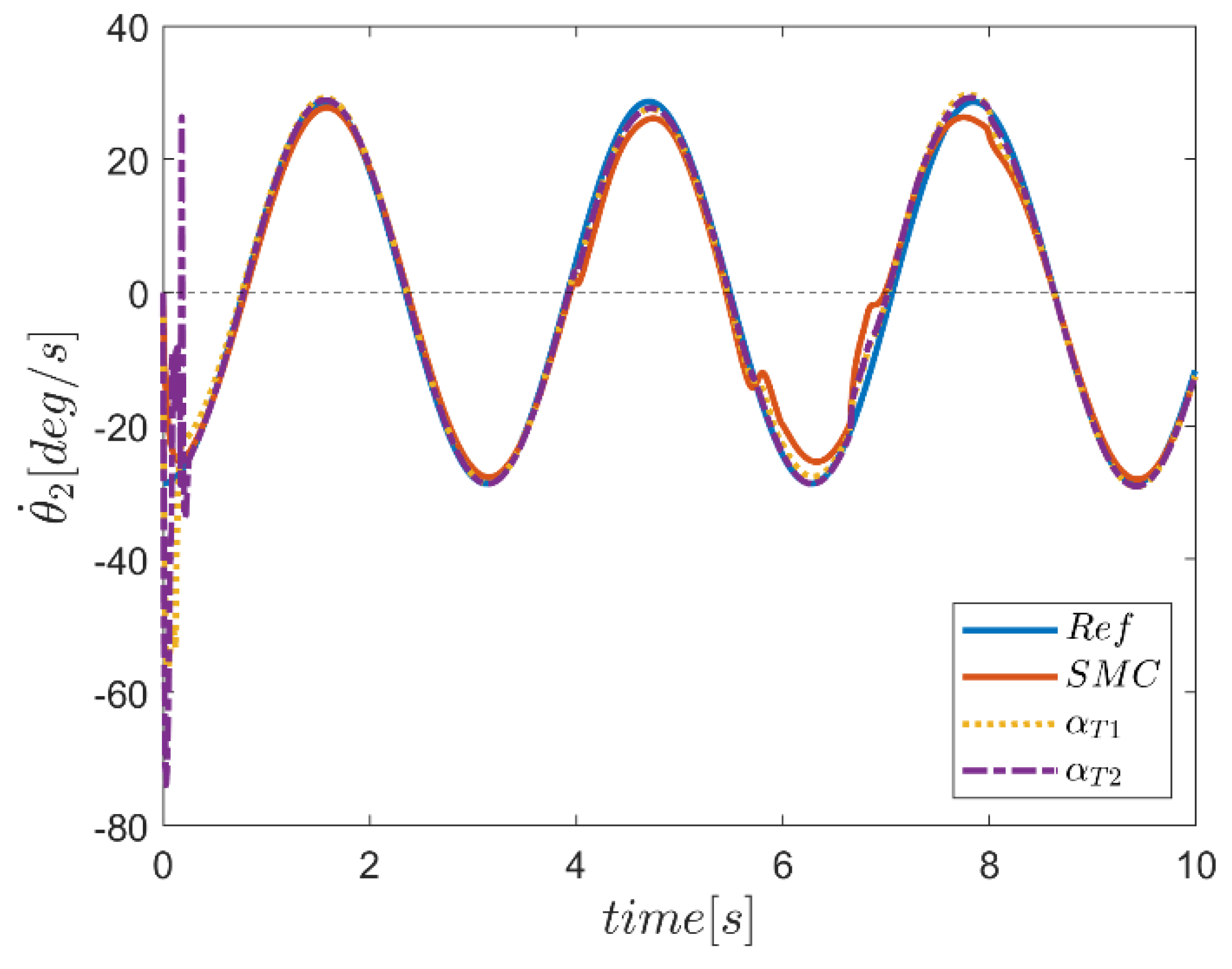
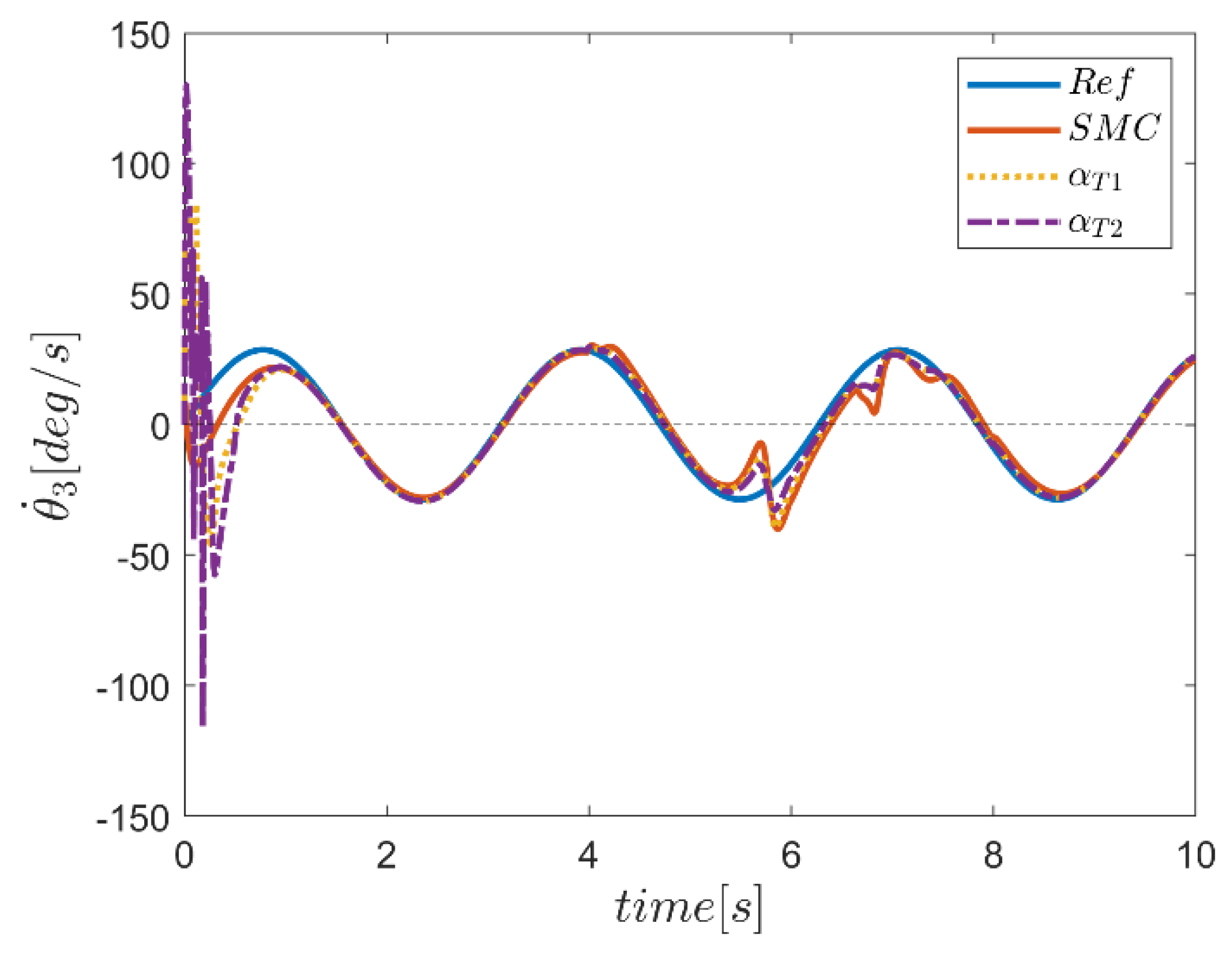
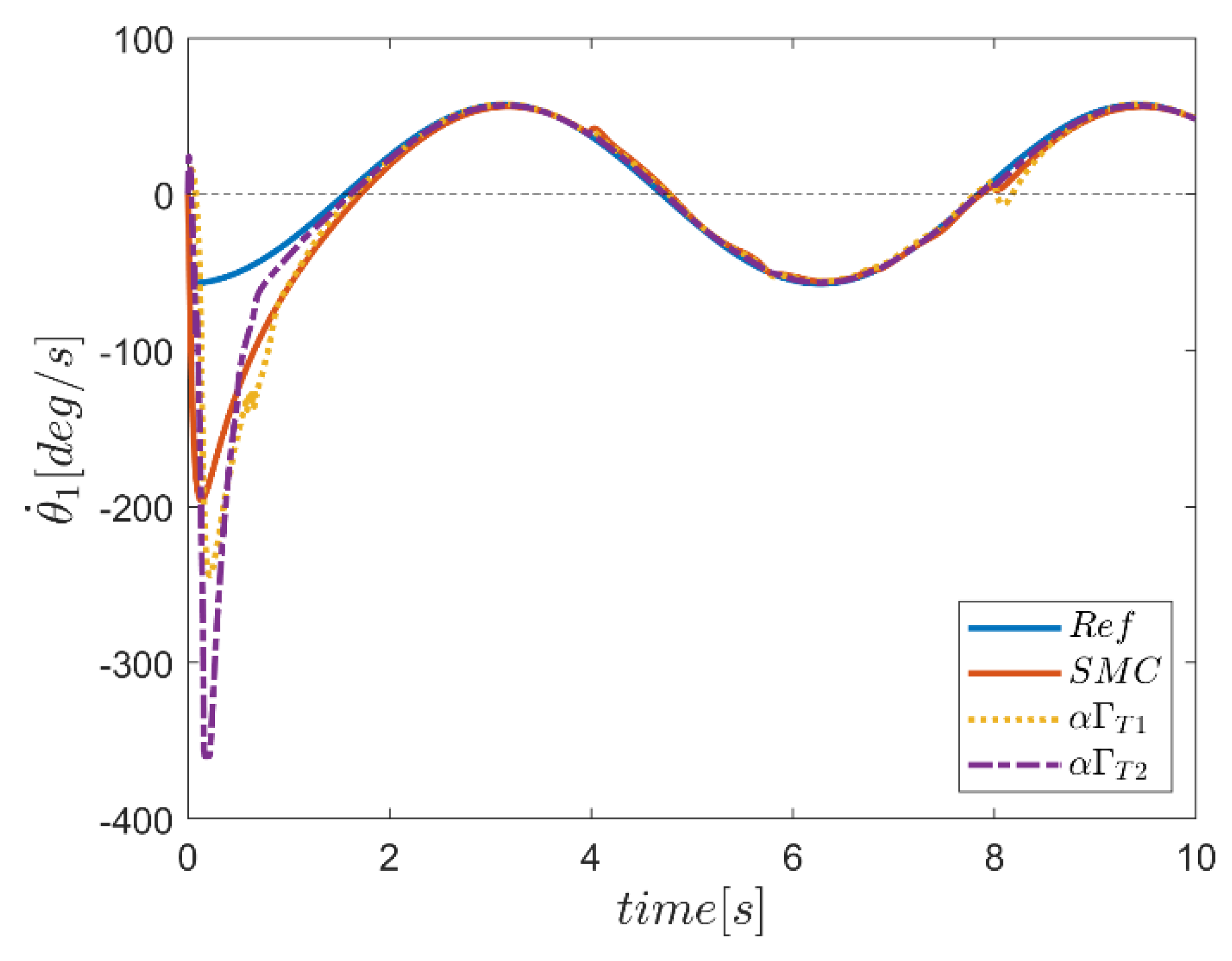
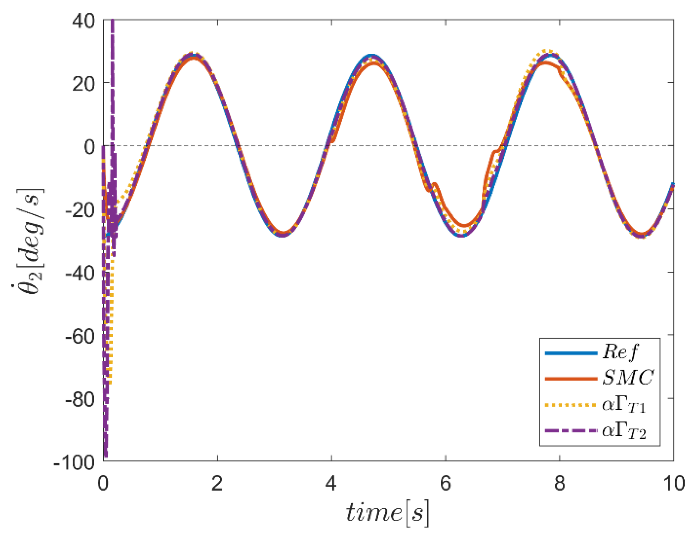
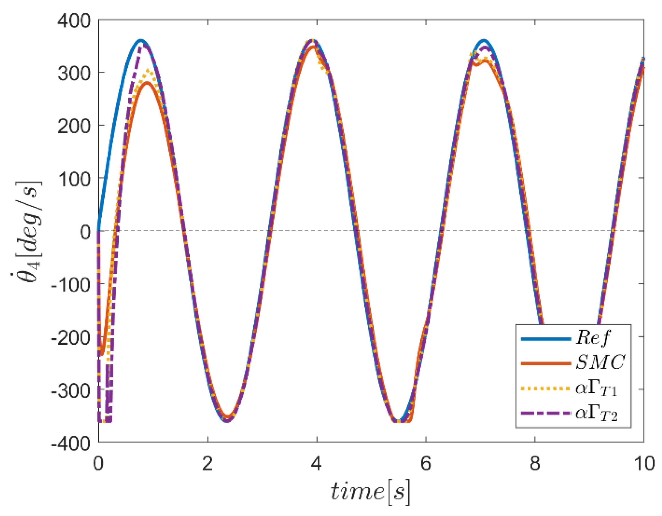
The graphs displaying temporal variation of velocity tracking in the joints based on type-1 and type-2 α fuzzy controllers as well as conventional sliding mode control are depicted in Figure 45, Figure 46, Figure 47, Figure 48, Figure 49 and Figure 50. In this section, in the transient region, we observed some drastic changes in system performance based on the control approaches of type-1 and type-2 α fuzzy systems, although in the remaining part of tracking reference speeds, the performance of controllers based on type-2 α fuzzy systems was much better than its counterparts. The performance of fuzzy systems was especially desirable in terms of stabilizing the system performance against external inputs. It is noteworthy that in joint number three, the reference speed tracking in the disturbance input region was somewhat weak. The important point regarding these curves is to keep the joint speeds below the limits. This limitation was seen in the angular velocity of joint number six in the transient region, for instance. Overall, the performance of the α type-2 fuzzy system was again superior compared with other controllers.
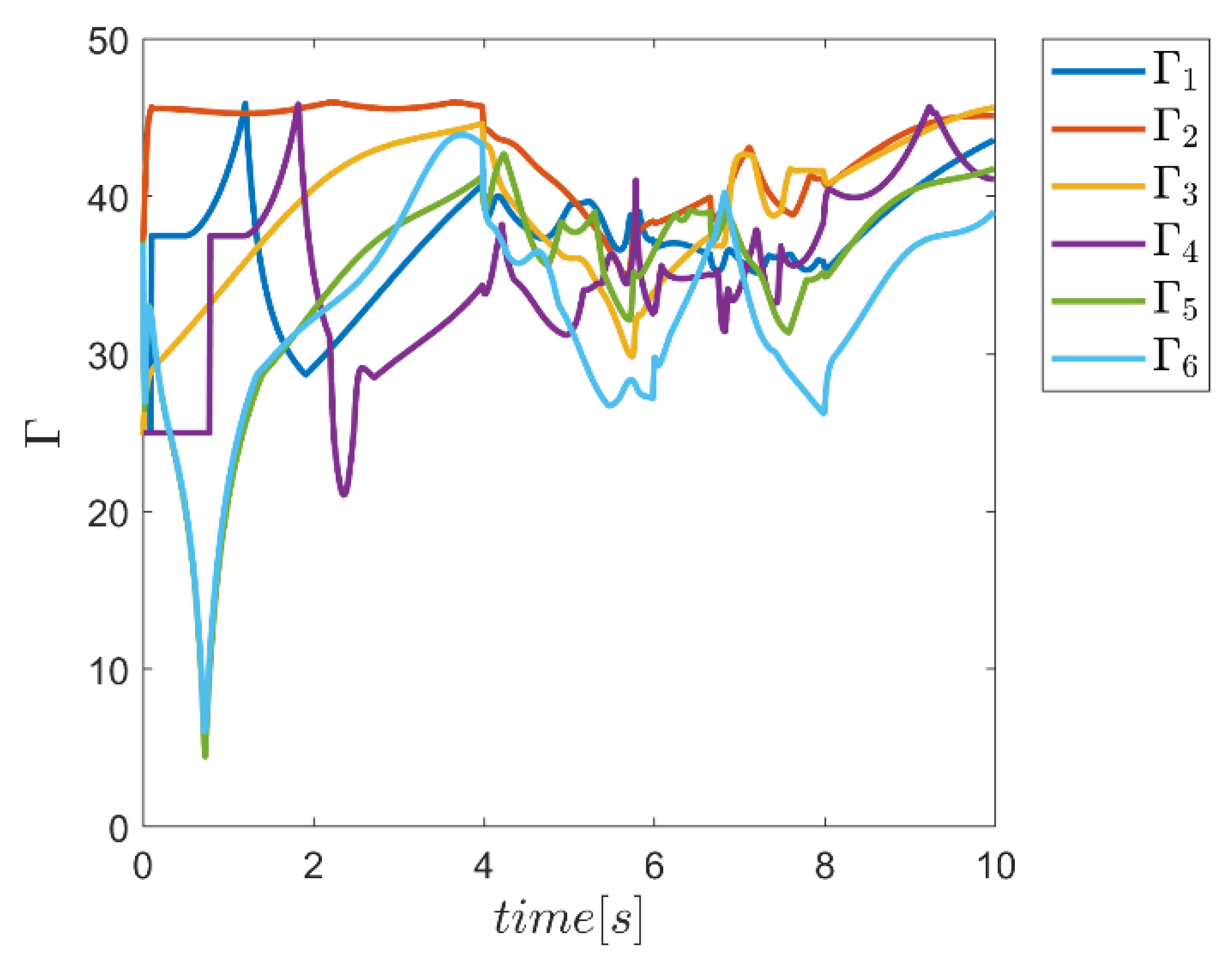
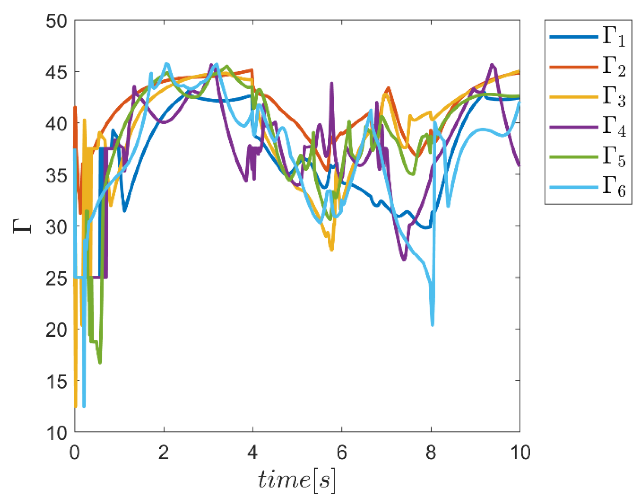
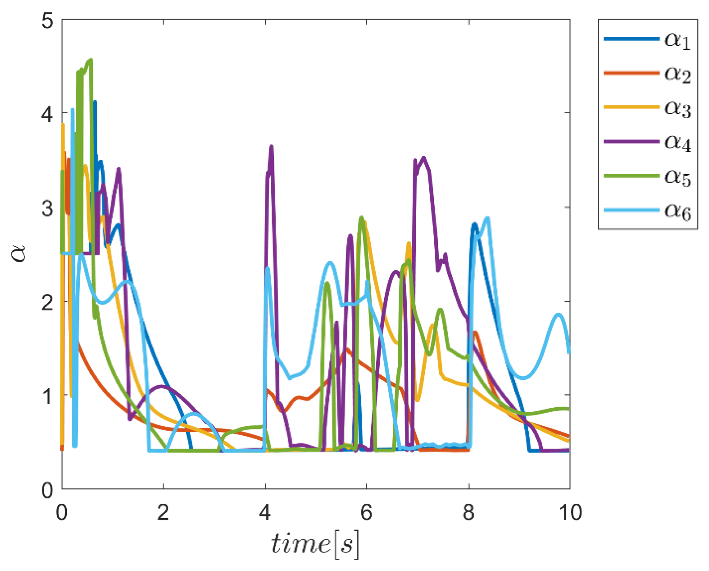
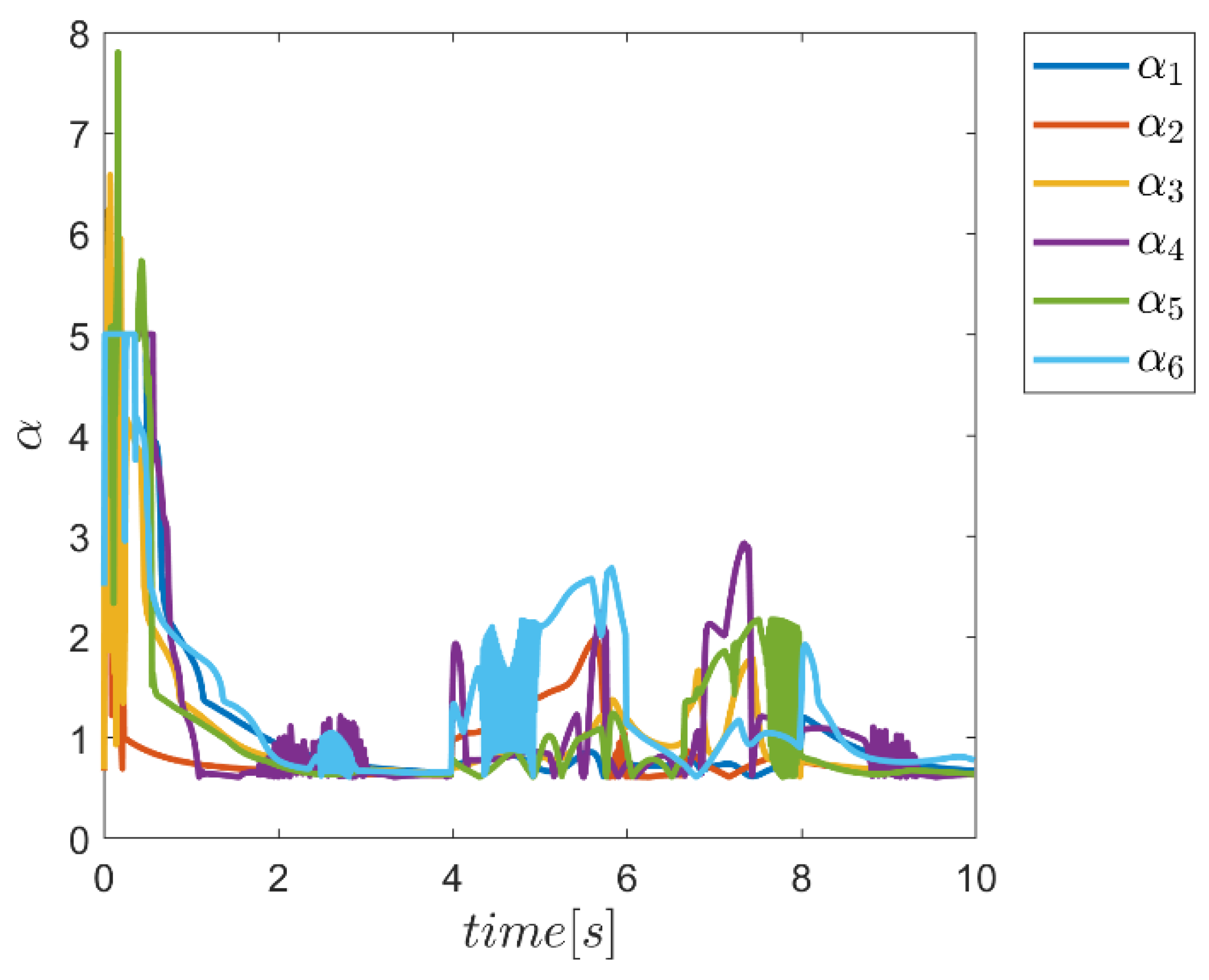
Figure 57, Figure 58, Figure 59, Figure 60, Figure 61, Figure 62, Figure 63 and Figure 64 show the capability of the proposed type-1 and -2 fuzzy systems in adaptively supplying the α and Γ coefficients for the sliding mode controller according to the working conditions of the robot manipulator in Γ, α alone and the α and Γ coefficients combined. In Figure 57, the Γ coefficients for the type-1 fuzzy system during the simulation time are plotted. According to the resulting curves, significant changes were observed in these coefficients over time. As shown, the change in the time interval of the disturbing external input effect was clearly significant, which indicated the effort of fuzzy systems to provide appropriate coefficients for the controller. Figure 58 illustrates the same coefficients for the type-2 fuzzy system. Compared with the type-1 fuzzy system, after the transient region, where significant changes were observed in all channels, these parameters regularly started decreasing, while in the range of the effect of input disturbances, these changes were milder than in type-1. The temporal variations of the α coefficient when using the α type-1 and -2 fuzzy systems are plotted in curves 59 and 60. According to the figures, the changes in this parameter in the transition region were significant and further showed a decreasing trend for both fuzzy systems. However, the process of change for this parameter in the type-2 fuzzy system was somewhat faster and also somewhat larger. In addition, the effect of the presence of external inputs in the interval of 4 to 8 s on these parameters in both systems was clear, which showed the system’s efforts to provide these coefficients optimally for the controller to face the adverse effects of undesirable inputs. Figure 61 and Figure 62 show the trend of changes of Γ coefficients related to type-1 and type-2 fuzzy systems, in which these coefficients were used in combination with the α coefficient to provide the control parameters. According to the resulting curves, significant changes in these coefficients were observed at the beginning of the tracking or transition zone, especially for the type-2 controller, which continued to calm down during the process of approximation changes in the type-2 fuzzy system. In the type-1 fuzzy system, the trend of changes of this parameter had significant changes during the tracking time. The temporal variations of the α coefficient in the case of the α types-1 and -2 fuzzy systems were plotted regarding the corresponding fuzzy systems for the Γ parameter in curves 63 and 64. Again, according to the figures, the trend of changes in this parameter in the transition zone was significant for both methods, particularly for the type-2 fuzzy system, while a decreasing trend was observed afterward in the application of both fuzzy systems. In addition, the effect of the presence of external inputs in the interval of 4 to 8 s on these parameters in both systems was quite clear. To summarize, it can be concluded that the compatible change of these parameters with the robot operating conditions over time indicated the ability of the proposed FSMC approaches to provide an appropriate amount of these parameters specially using type-2 fuzzy systems.
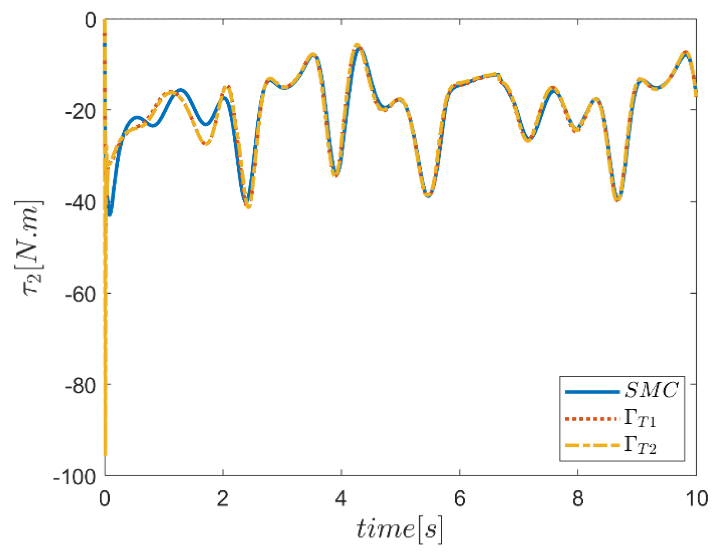
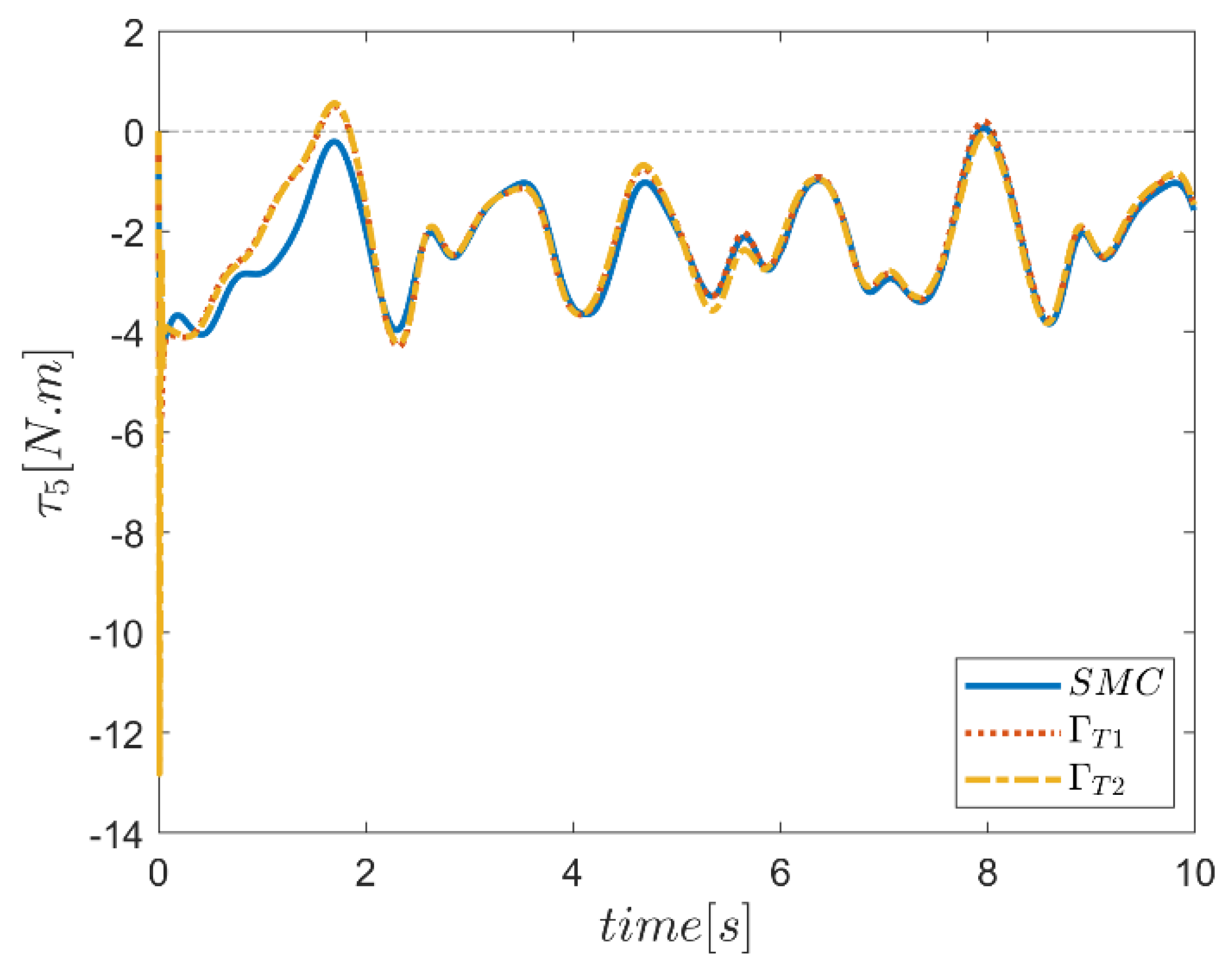
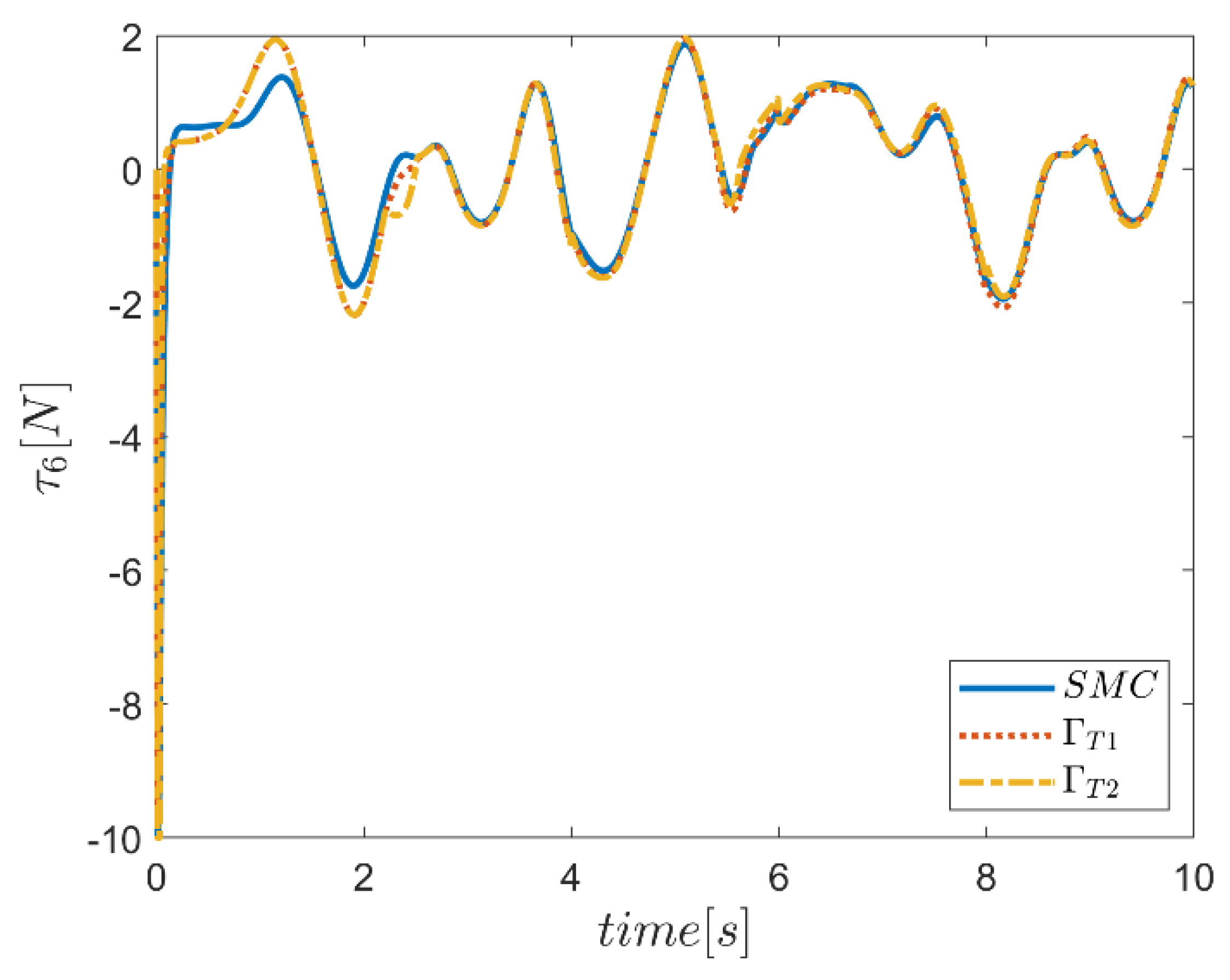
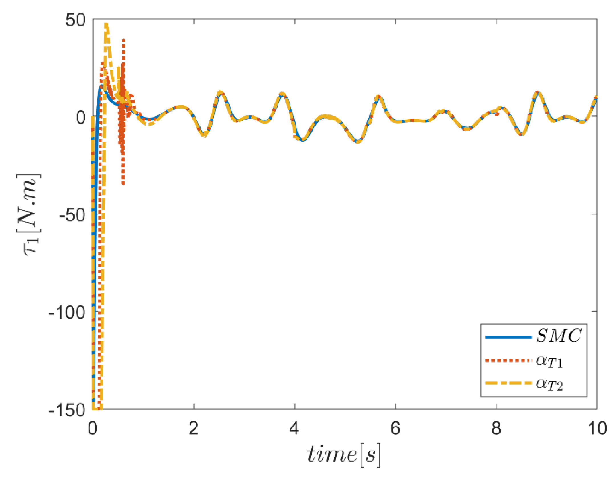
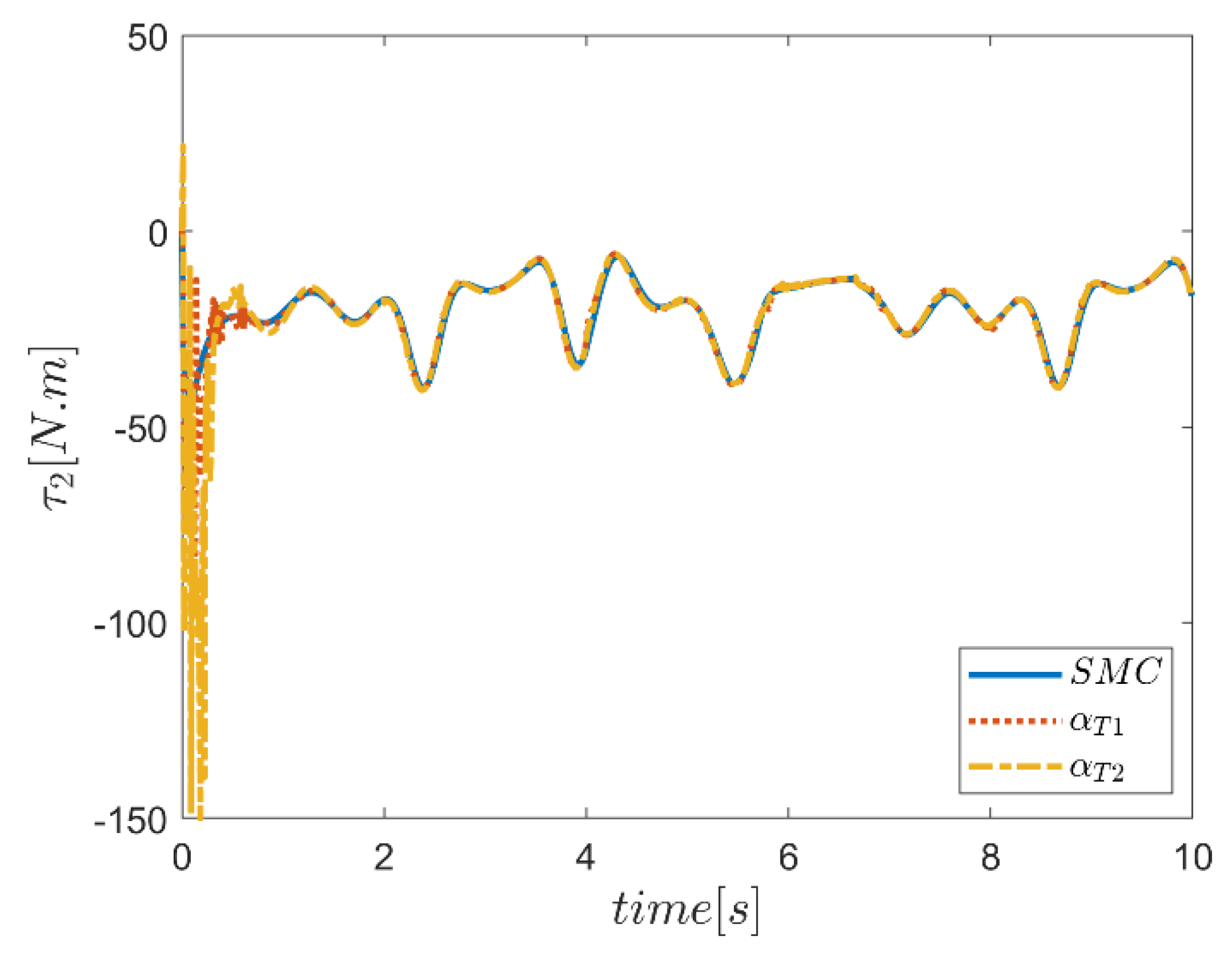
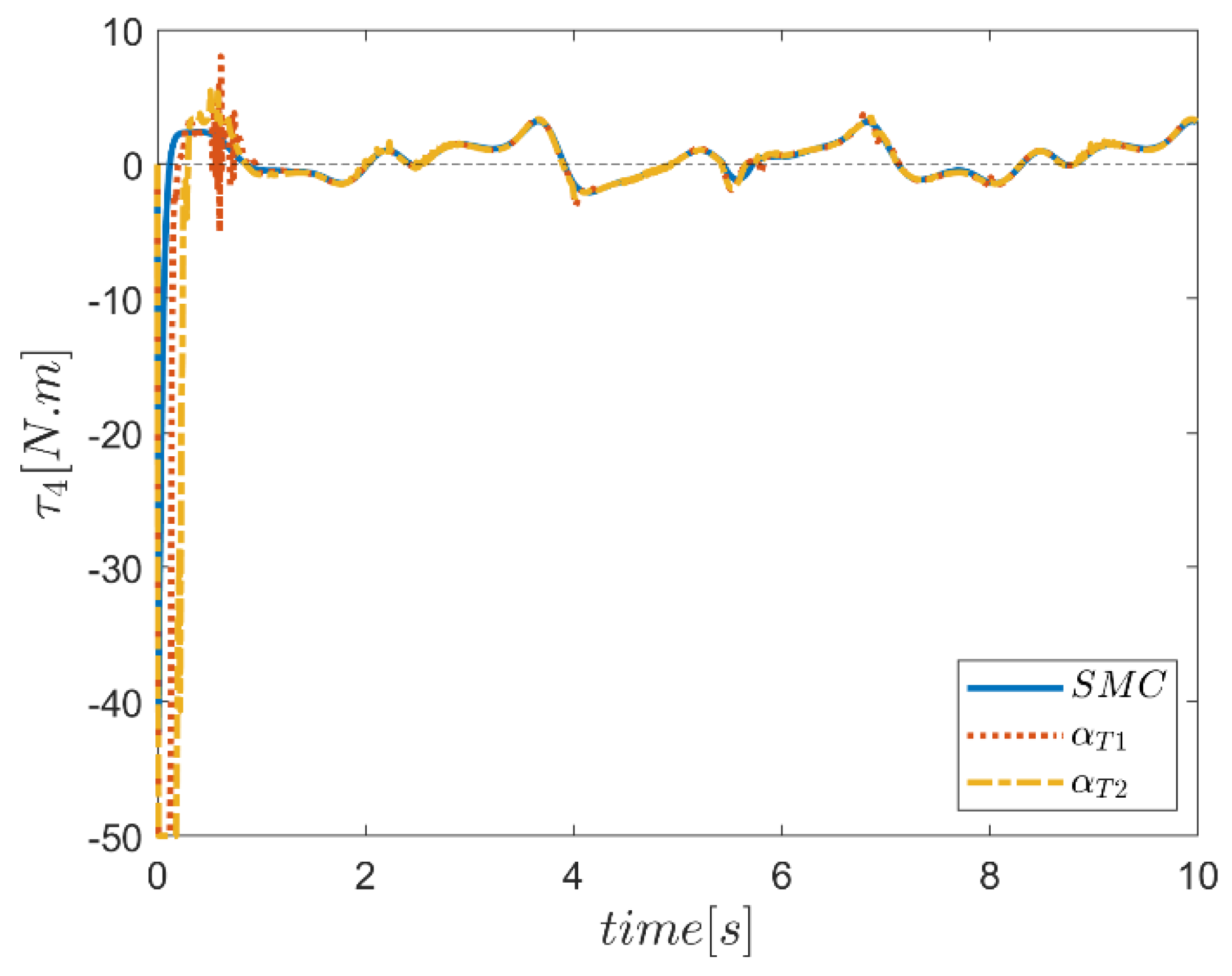
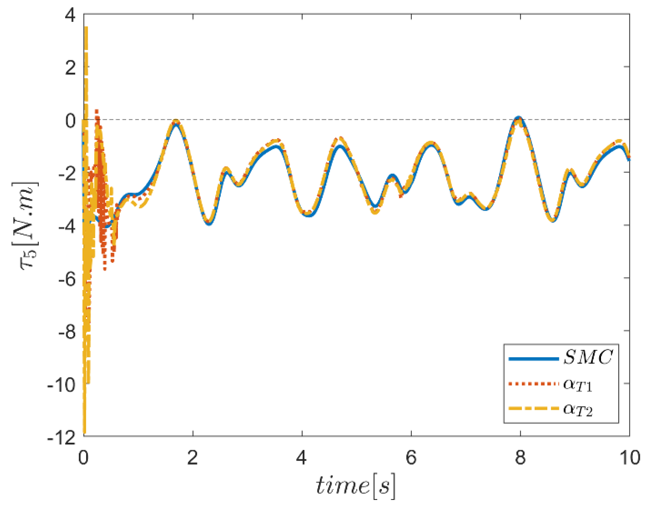
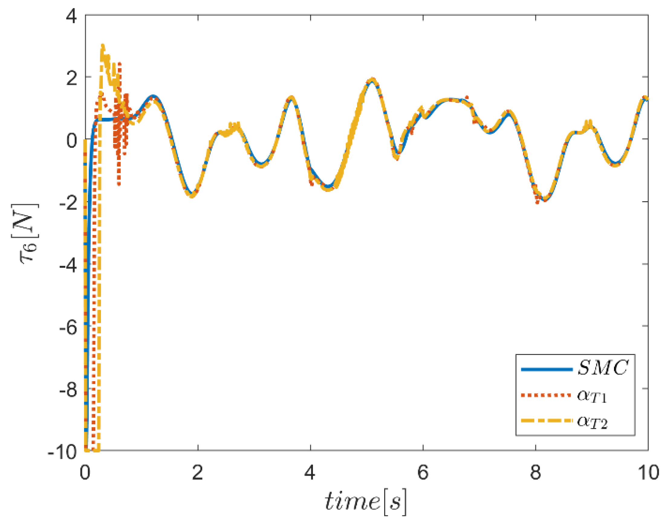
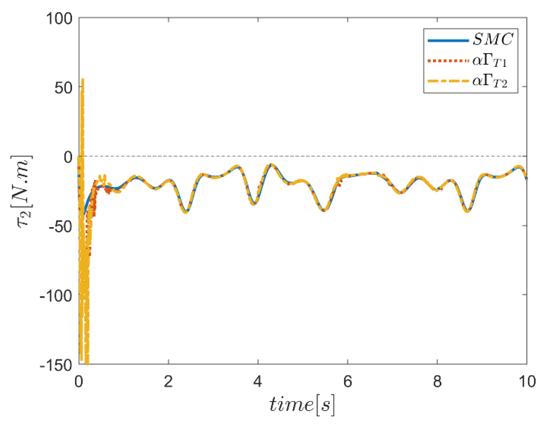
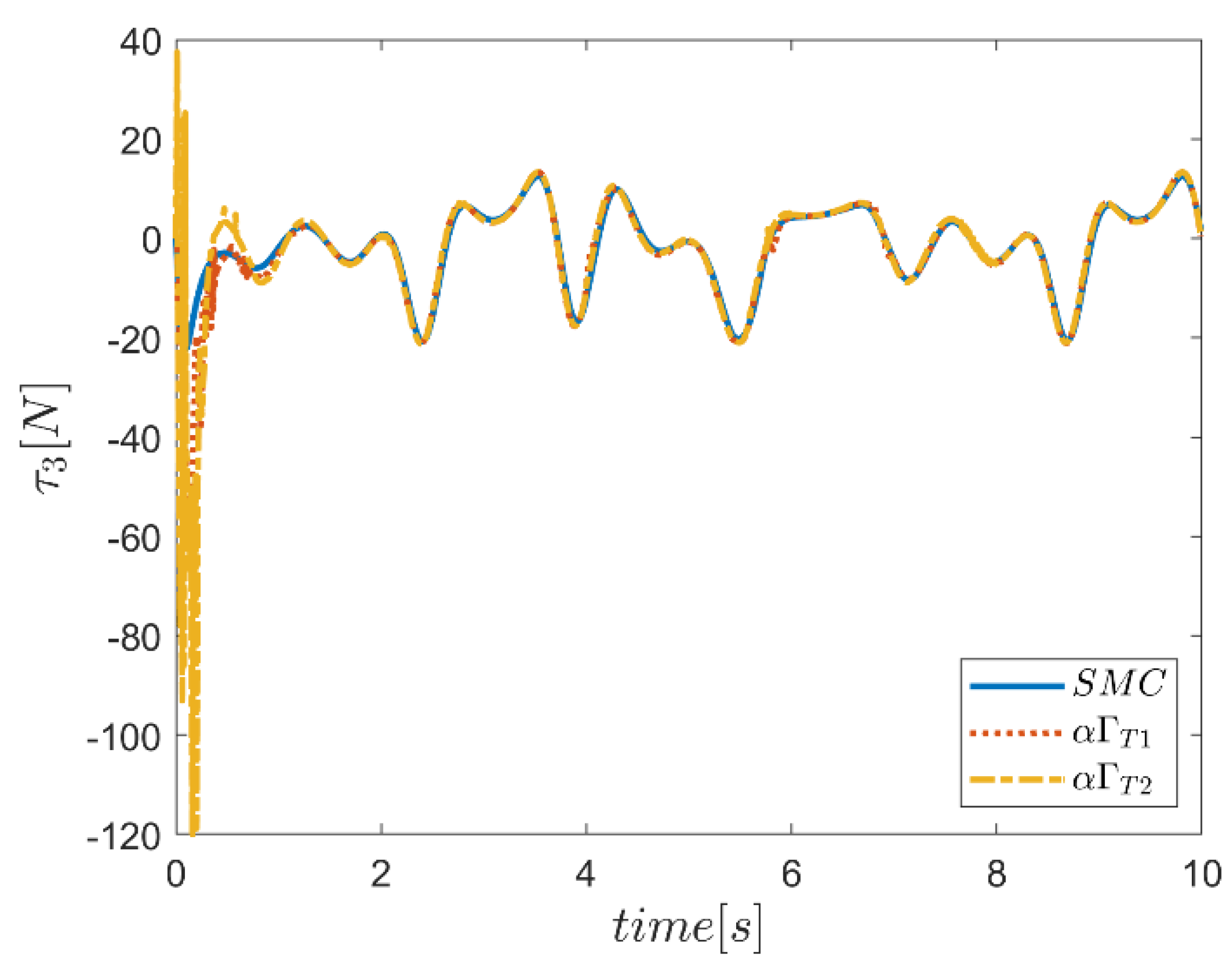
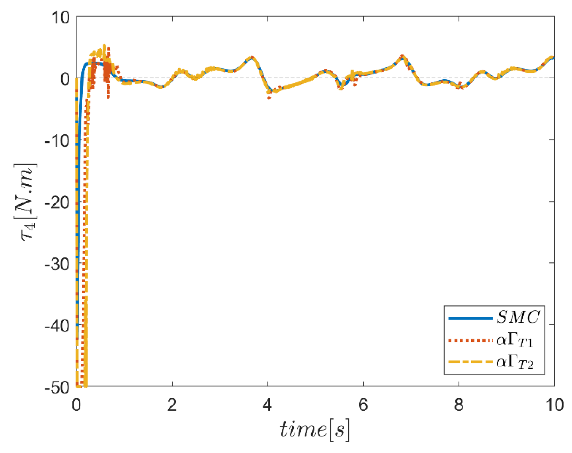
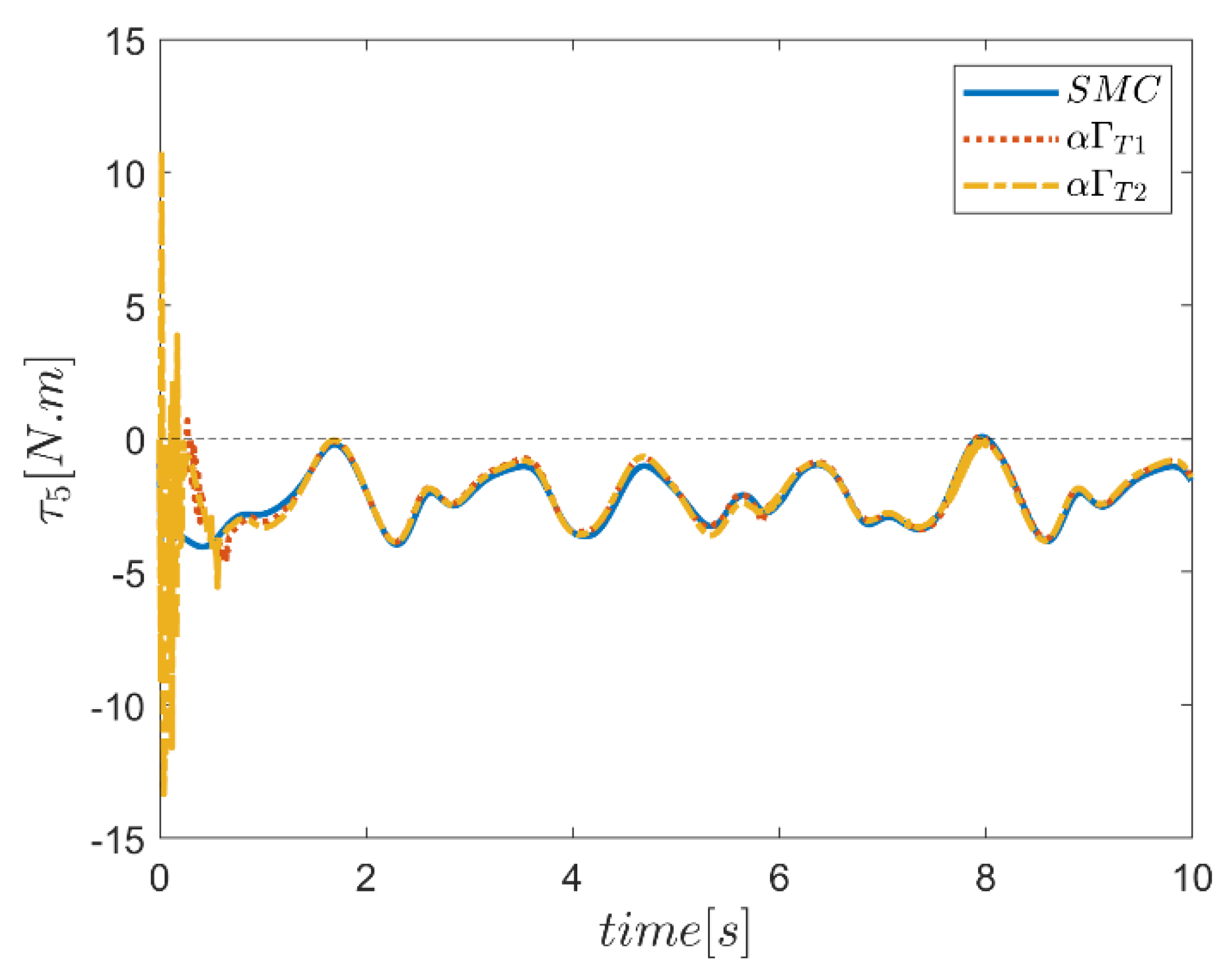
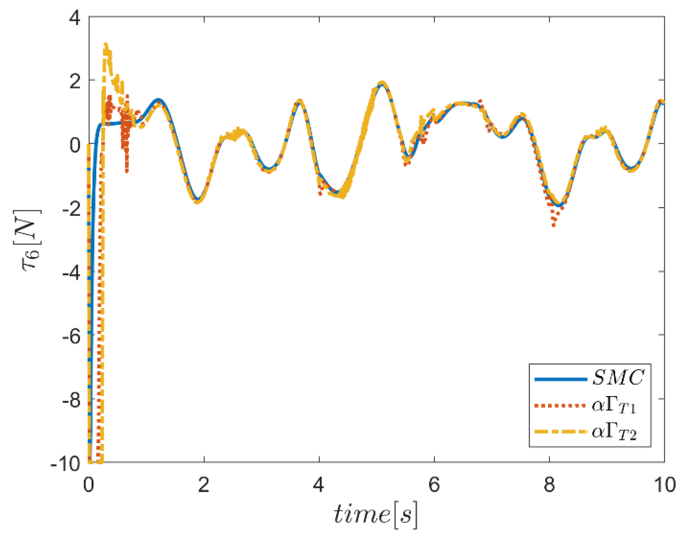
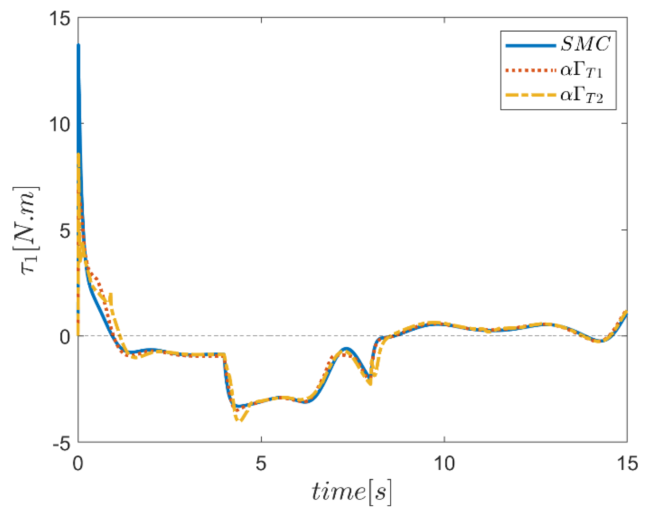
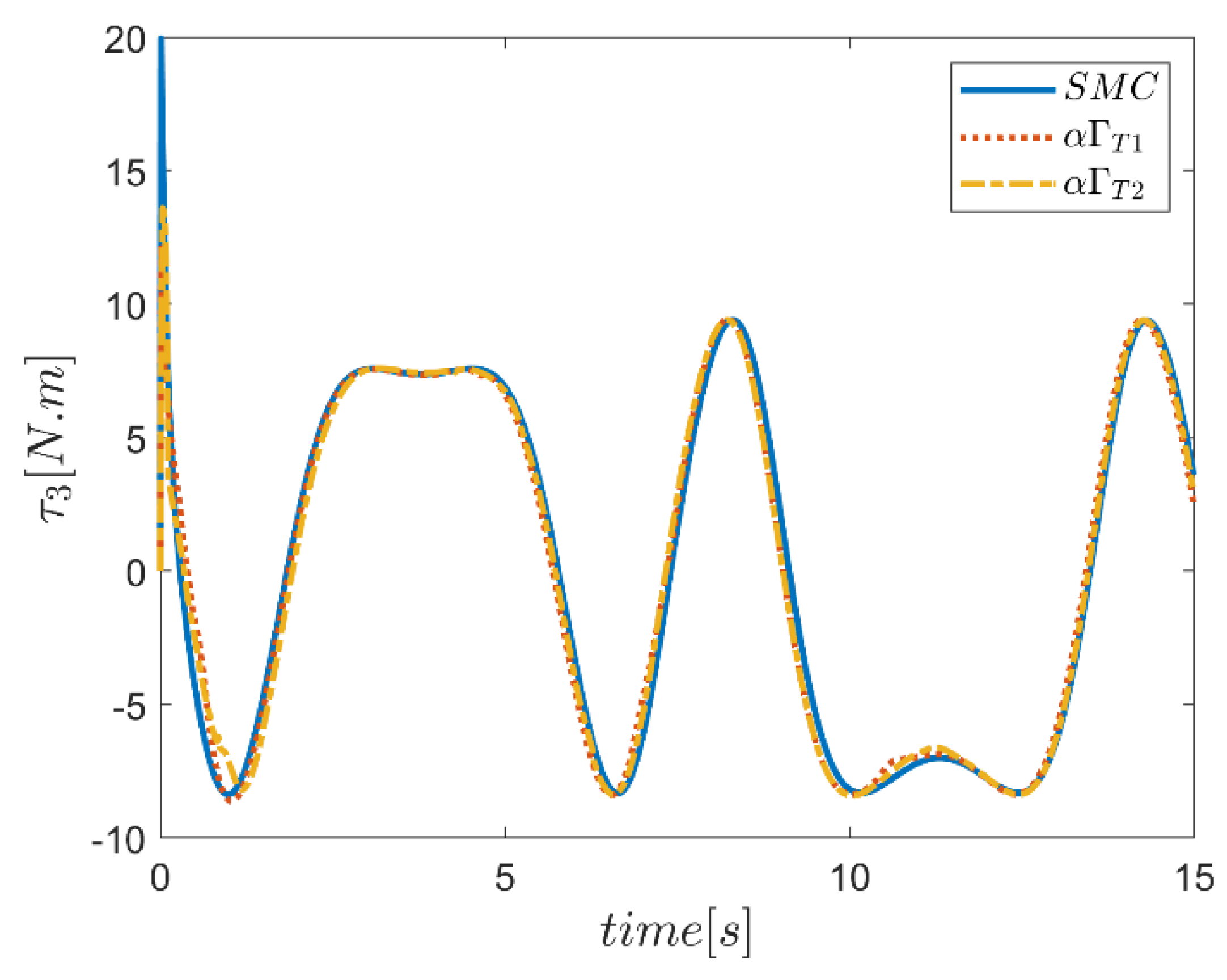
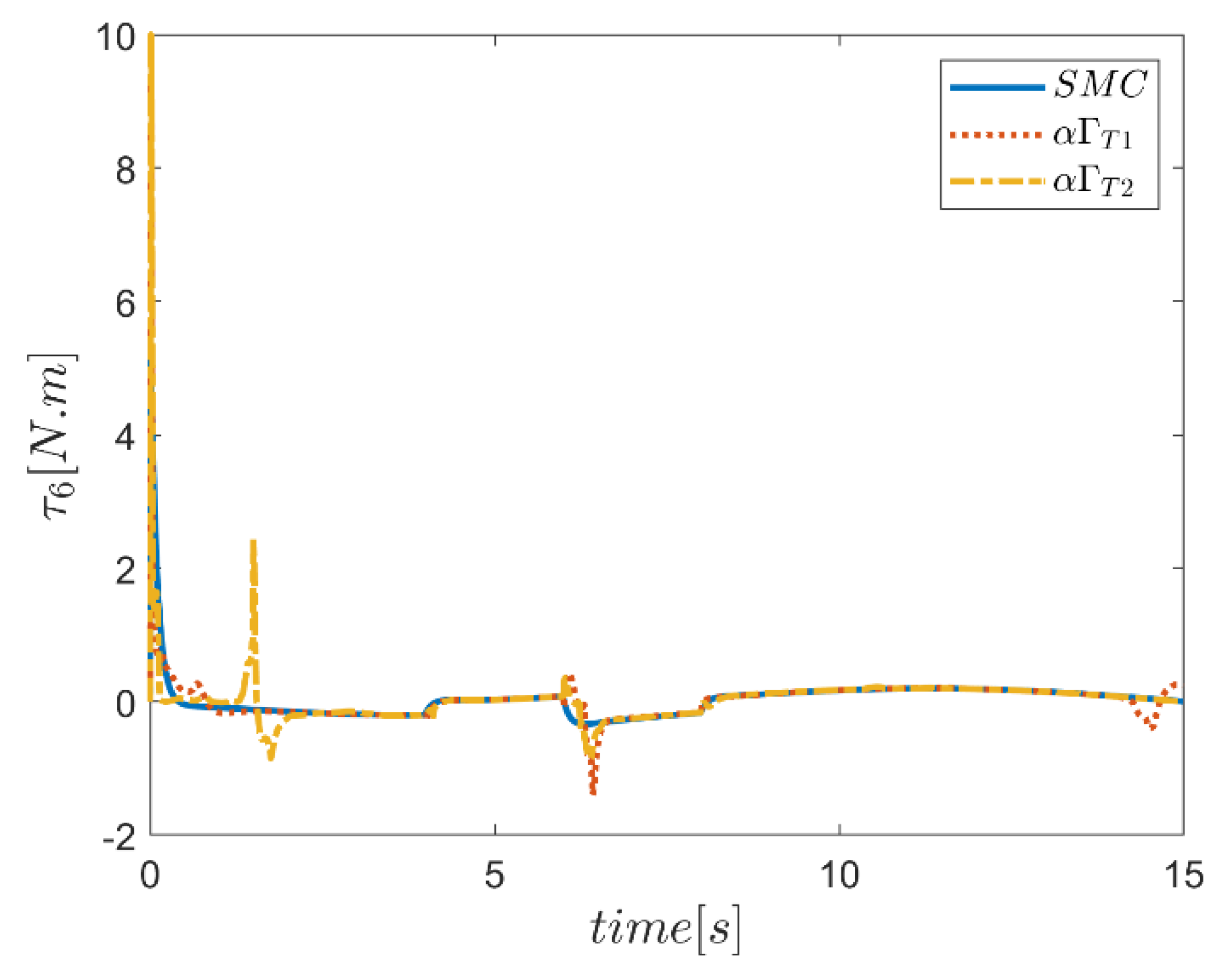
The control inputs versus simulation time for all proposed control methods are illustrated in Figure 65, Figure 66, Figure 67, Figure 68, Figure 69, Figure 70, Figure 71, Figure 72, Figure 73, Figure 74, Figure 75, Figure 76, Figure 77, Figure 78, Figure 79, Figure 80, Figure 81 and Figure 82. It is noteworthy that in all methods, significant changes in the value of the input torques were observed at the initial moment of tracking the desired trajectory. However, all control inputs were kept in the allowed window due to the applied limits on the output of controllers to match the case with the actual operating conditions. In curves 65 to 70, where the control inputs were drawn at the joints for the sliding mode controller along with the Γ fuzzy sliding mode controllers, the behavior was relatively the same for all methods. According to the results, in some cases, actuator saturation in the transient region occurred. Additionally, the changes of control inputs in the application of the type-2 fuzzy system in the transient region were slightly more severe than the type-1 fuzzy system, which of course can be seen in the full compliance of control inputs for all methods. Input torques for α fuzzy systems alone are plotted in Figure 71, Figure 72, Figure 73, Figure 74, Figure 75 and Figure 76. According to the results, with the exception of the transient input area, the same performance was observed for all controllers. In the transient region, the amount of torque was significant for all control approaches and sometimes led to actuator saturation, but in control approaches using type-1 and -2 fuzzy systems, more control demand was observed than the SMC. The amount of change in the use of type-2 fuzzy systems, of course, is almost greater than the type-1 fuzzy system approach. In curves 77 to 82, the control inputs at the robot joints are plotted for all three approaches of conventional sliding mode controllers and fuzzy sliding mode controllers using the combined α and Γ fuzzy systems to adjust the controller parameters. It was noted that the control changes in this mode were more balanced than in the case of α fuzzy control alone. Although there was more control input demand in the use of the type-2 fuzzy system approach than in the type-1 fuzzy system, the changes in the control approach based on the type-2 fuzzy system were much smoother than those of the type-1 fuzzy system. To summarize the results for control inputs, it was briefly observed that in the control approach based on type-2 fuzzy systems, which use a combination of α and Γ type-2 fuzzy systems to adjust the controller parameters, the control demand with quality and optimal changes of parameters for meeting the control objectives were adaptively provided, which showed the effectiveness of the method and the achievement of the objectives of this study.
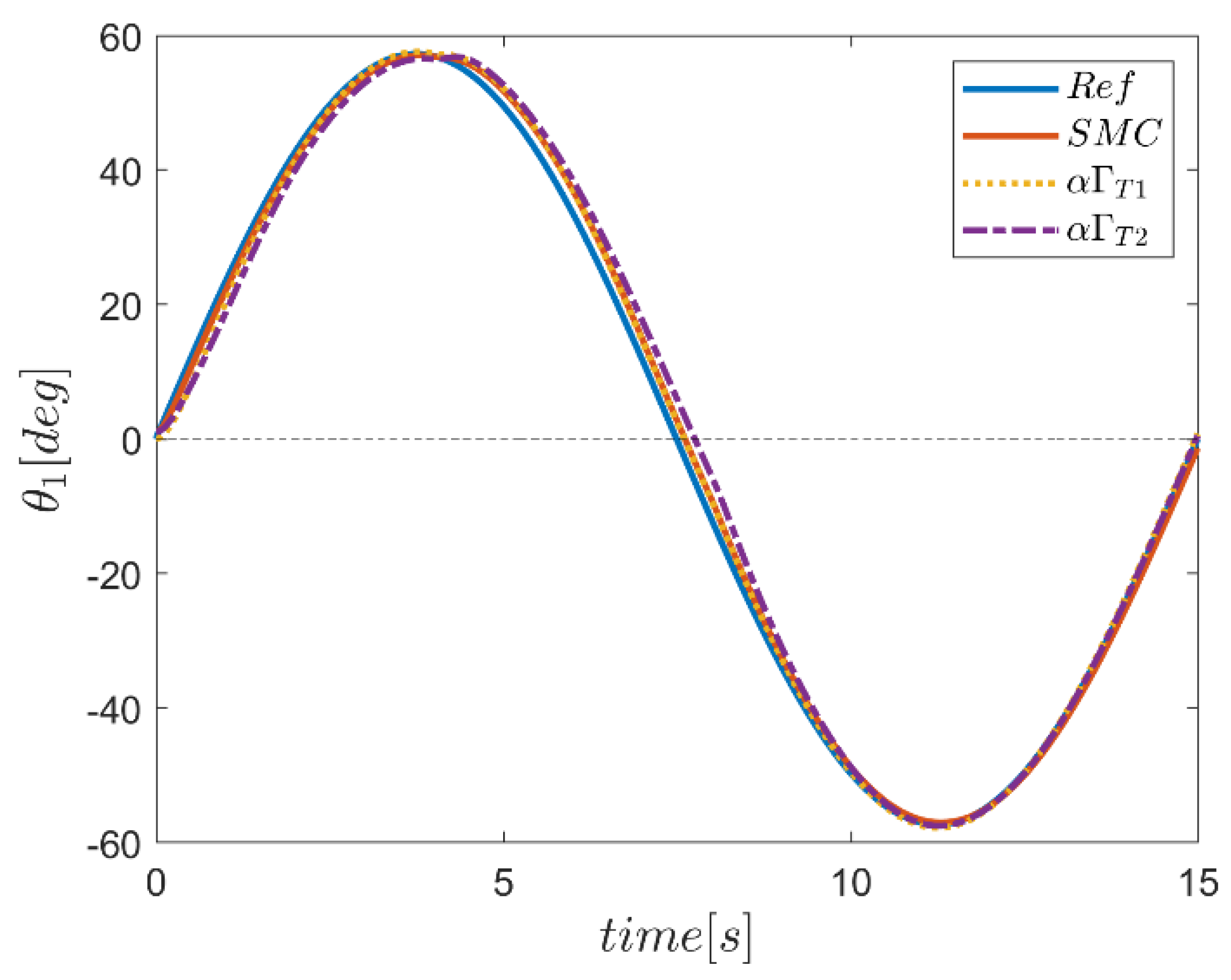
In order to further illustrating the effectiveness of the proposed controller system, the results of the simulation of tracking the reference inputs for the PUMA 560 robot according to reference [40] are presented in the Figure 83, Figure 84, Figure 85, Figure 86, Figure 87, Figure 88, Figure 89, Figure 90, Figure 91, Figure 92 and Figure 93. It should be noted that in order to prevent the article from becoming too long, only the joint reference path tracking the actuator torques using combined fuzzy systems αΓ are presented. The tracking quality of the sinusoidal reference inputs in all joints for the conventional sliding mode and αΓ type-1 and -2 fuzzy system controllers are plotted in Figure 83, Figure 84, Figure 85, Figure 86, Figure 87 and Figure 88. In the referenced article, a significant trajectory error was observed, but on the contrary, the exact tracking of the reference inputs was achieved using all conventional and fuzzy assisted SMC control methods. At the beginning of the tracking, the controller system based on the type-2 fuzzy system showed a small deviation, but further investigation revealed the more appropriate performance of this controller along the trajectory compared with the controller counterparts.

7. Conclusions

In this paper, the six-degree-of-freedom robot manipulator using a type-2 fuzzy sliding mode control (T2FSMC) approach in which type-2 fuzzy systems were used to adaptively adjust the sliding surface slope coefficients and the gains of switching control part of the SMC controller was presented. When setting up the fuzzy sliding mode controller, an optimal design approach based on a genetic algorithm (GA) optimization method was used to tune the table of rules and parameters of the output membership functions of type-2 fuzzy systems. According to the proposed design approach, the need for expert knowledge in fuzzy system design was eliminated and the uncertainty effects in defining membership functions were optimally considered. In addition, by managing the range of universe of discourse of output parameters during the design of fuzzy systems, preventing saturation of the actuators became possible. The performance of the proposed controller in delivering the proper optimal parameters of the sliding mode control systems using fuzzy type-2 systems was examined over controlling the UR5 robot arm. Simulation results of the proposed controller in comparison with the fuzzy sliding mode controllers of type-1 and the conventional sliding mode controller clearly indicated improved performance of the proposed control system. The generalizable features of the proposed control method make it possible to develop the method for a variety of multi-input-multi-output nonlinear systems. The aim of improving the comprehensiveness of the presented control approach as an efficient and practically implementable sliding mode control approach with fuzzy gain scheduling, especially for nonlinear systems with high degrees of freedom without demanding significant computing and hardware costs, will be considered in future work. In this regard, complementary components such as additional plugins to deal with the actuators and sensors faults are to be considered as the future extension of the present paper.

Author Contributions

Conceptualization, Y.B., K.A.A., O.A. and S.M.; formal analysis, S.M., O.A., S.B.A. and M.A.R.; funding acquisition, O.A. and S.B.A.; investigation, K.A.A., S.B.A. and S.M.; methodology, S.M. and Y.B.; writing—original draft, Y.B., K.A.A., O.A. and S.M.; writing—review and editing Y.B.; supervision, S.M., O.A., M.A.R. and Y.B. All authors have read and agreed to the published version of the manuscript.

Funding

This research has been funded by Deputy for Research & Innovation, Ministry of Education through Initiative of Institutional Funding at University of Ha’il-Saudi Arabia through project number IFP-22 031.

Institutional Review Board Statement

Not applicable.

Informed Consent Statement

Not applicable.

Data Availability Statement

The data that support the findings of this study are available within the article.

Conflicts of Interest

The authors declare no conflict of interest.

References

  1. Alattas, K.A.; Bouteraa, Y.; Rahmani, R.; Fekih, A.; Mobayen, S.; Assawinchaichote, W. Optimized Fuzzy Enhanced Robust Control Design for a Stewart Parallel Robot. Mathematics 2022, 10, 1917. [Google Scholar]
  2. Liu, H.; Zhang, T. Fuzzy sliding mode control of robotic manipulators with kinematic and dynamic uncertainties. J. Dyn. Syst. Meas. Control. 2012, 134, 061007. [Google Scholar] [CrossRef]
  3. Yagiz, N.; Hacioglu, Y. Robust control of a spatial robot using fuzzy sliding modes. Math. Comput. Model. 2009, 49, 114–127. [Google Scholar] [CrossRef]
  4. Maalej, B.; Medhaffar, H.; Chemori, A.; Derbel, N. A Fuzzy Sliding Mode Controller for Reducing Torques Applied to a Rehabilitation Robot. In Proceedings of the 2020 17th International Multi-Conference on Systems, Signals & Devices (SSD), Sfax, Tunisia, 20–23 July 2020; pp. 740–746. [Google Scholar]
  5. Zheng, K.; Hu, Y.; Wu, B. Intelligent fuzzy sliding mode control for complex robot system with disturbances. Eur. J. Control. 2020, 51, 95–109. [Google Scholar] [CrossRef]
  6. Ren, L.-T.; Xie, S.-S.; Miao, Z.-G.; Tian, H.-S.; Peng, J.-B. Fuzzy robust sliding mode control of a class of uncertain systems. J. Cent. South Univ. 2016, 23, 2296–2304. [Google Scholar] [CrossRef]
  7. Wu, Q.; Wang, X.; Du, F.; Zhu, Q. Fuzzy sliding mode control of an upper limb exoskeleton for robot-assisted rehabilitation. In Proceedings of the 2015 IEEE International Symposium on Medical Measurements and Applications (MeMeA) Proceedings, Torino, Italy, 7–9 May 2015; pp. 451–456. [Google Scholar]
  8. Razzaghian, A.; Moghaddam, R.K. Fuzzy sliding mode control of 5 DOF upper-limb exoskeleton robot. In Proceedings of the 2015 International Congress on Technology, Communication and Knowledge (ICTCK), Mashhad, Iran, 11–12 November 2015; pp. 25–32. [Google Scholar]
  9. Qureshi, M.S.; Swarnkar, P.; Gupta, S. A supervisory on-line tuned fuzzy logic based sliding mode control for robotics: An application to surgical robots. Robot. Auton. Syst. 2018, 109, 68–85. [Google Scholar] [CrossRef]
  10. Soltanpour, M.R.; Khooban, M.H. A particle swarm optimization approach for fuzzy sliding mode control for tracking the robot manipulator. Nonlinear Dyn. 2013, 74, 467–478. [Google Scholar] [CrossRef]
  11. Taran, B.; Pirmohammadi, A. Designing an optimal fuzzy sliding mode control for a two-link robot. J. Braz. Soc. Mech. Sci. Eng. 2019, 42, 5. [Google Scholar] [CrossRef]
  12. Xie, Z.; Sun, T.; Kwan, T.; Wu, X. Motion control of a space manipulator using fuzzy sliding mode control with reinforcement learning. Acta Astronaut. 2020, 176, 156–172. [Google Scholar] [CrossRef]
  13. Vijay, M.; Jena, D. PSO based neuro fuzzy sliding mode control for a robot manipulator. J. Electr. Syst. Inf. Technol. 2017, 4, 243–256. [Google Scholar] [CrossRef] [Green Version]
  14. Balcazar, R.; Rubio, J.d.J.; Orozco, E.; Andres Cordova, D.; Ochoa, G.; Garcia, E.; Pacheco, J.; Gutierrez, G.J.; Mujica-Vargas, D.; Aguilar-Ibañez, C. The Regulation of an Electric Oven and an Inverted Pendulum. Symmetry 2022, 14, 759. [Google Scholar] [CrossRef]
  15. Rubio, J.D.J.; Orozco, E.; Cordova, D.A.; Islas, M.A.; Pacheco, J.; Gutierrez, G.J.; Zacarias, A.; Soriano, L.A.; Meda-Campaña, J.A.; Mujica-Vargas, D. Modified linear technique for the controllability and observability of robotic arms. IEEE Access 2022, 10, 3366–3377. [Google Scholar] [CrossRef]
  16. Meda-Campaña, J.A.; Rodríguez-Manzanarez, R.A.; Ontiveros-Paredes, S.D.; Rubio, J.d.J.; Tapia-Herrera, R.; Hernández-Cortés, T.; Obregón-Pulido, G.; Aguilar-Ibáñez, C. An Algebraic Fuzzy Pole Placement Approach to Stabilize Nonlinear Mechanical Systems. IEEE Trans. Fuzzy Syst. 2022, 30, 3322–3332. [Google Scholar] [CrossRef]
  17. Lughofer, E.; Skrjanc, I. Evolving Error Feedback Fuzzy Model for Improved Robustness under Measurement Noise. IEEE Trans. Fuzzy Syst. 2022, 1–12. [Google Scholar] [CrossRef]
  18. Soriano, L.A.; Zamora, E.; Vazquez-Nicolas, J.M.; Hernández, G.; Barraza Madrigal, J.A.; Balderas, D. PD Control Compensation Based on a Cascade Neural Network Applied to a Robot Manipulator. Frontiers in Neurorobotics 2020, 14, 577749. [Google Scholar] [CrossRef]
  19. Silva-Ortigoza, R.; Hernández-Márquez, E.; Roldán-Caballero, A.; Tavera-Mosqueda, S.; Marciano-Melchor, M.; García-Sánchez, J.R.; Hernández-Guzmán, V.M.; Silva-Ortigoza, G. Sensorless Tracking Control for a “Full-Bridge Buck Inverter–DC Motor” System: Passivity and Flatness-Based Design. IEEE Access 2021, 9, 132191–132204. [Google Scholar] [CrossRef]
  20. Chin, C.S.; Lin, W.P. Robust genetic algorithm and fuzzy inference mechanism embedded in a sliding-mode controller for an uncertain underwater robot. IEEE/ASME Trans. Mechatron. 2018, 23, 655–666. [Google Scholar] [CrossRef] [Green Version]
  21. Huaman-Loayza, A.S. Path-Following of a Quadrotor Using Fuzzy Sliding Mode Control. In Proceedings of the 2018 IEEE XXV International Conference on Electronics, Electrical Engineering and Computing (INTERCON), Lima, Peru, 8–10 August 2018; pp. 1–4. [Google Scholar]
  22. Hu, S.B.; Lu, M.X. Backstepping Fuzzy Sliding Mode Control for a Three-Links Spatial Robot Based on Variable Rate Reaching Law. Appl. Mech. Mater. 2011, 105–107, 2213–2216. [Google Scholar] [CrossRef]
  23. Khanesar, M.A.; Branson, D. Robust Sliding Mode Fuzzy Control of Industrial Robots Using an Extended Kalman Filter Inverse Kinematic Solver. Energies 2022, 15, 1876. [Google Scholar] [CrossRef]
  24. Li, F.; Zhang, Z.; Wu, Y.; Chen, Y.; Liu, K.; Yao, J. Improved fuzzy sliding mode control in flexible manipulator actuated by PMAs. Robotica 2022, 40, 2683–2696. [Google Scholar] [CrossRef]
  25. Bao, L.; Kim, D.; Yi, S.-J.; Lee, J. Design of a Sliding Mode Controller with Fuzzy Rules for a 4-DoF Service Robot. Int. J. Control. Autom. Syst. 2021, 19, 2869–2881. [Google Scholar] [CrossRef]
  26. Ashagrie, A.; Salau, A.O.; Weldcherkos, T. Modeling and control of a 3-DOF articulated robotic manipulator using self-tuning fuzzy sliding mode controller. Cogent Eng. 2021, 8, 1950105. [Google Scholar] [CrossRef]
  27. Akhenak, A.; Chadli, M.; Ragot, J.; Maquin, D. Fault detection and isolation using sliding mode observer for uncertain Takagi-Sugeno fuzzy model. In Proceedings of the 2008 16th Mediterranean Conference on Control and automation, Ajaccio, France, 25–27 June 2008; pp. 286–291. [Google Scholar]
  28. El Hajjaji, A.; Chadli, M.; Oudghiri, M.; Pages, O. Observer-based robust fuzzy control for vehicle lateral dynamics. In Proceedings of the 2006 American Control Conference, Minneapolis, MN, USA, 14–16 June 2006; p. 6. [Google Scholar]
  29. Mohamed, K.; Chadli, M.; Chaabane, M. Unknown inputs observer for a class of nonlinear uncertain systems: An LMI approach. Int. J. Autom. Comput. 2012, 9, 331–336. [Google Scholar] [CrossRef]
  30. Castillo, O.; Melin, P.; Kacprzyk, J.; Pedrycz, W. Type-2 Fuzzy Logic: Theory and Applications. In Proceedings of the 2007 IEEE International Conference on Granular Computing (GRC 2007), San Jose, CA, USA, 2–4 November 2007; p. 145. [Google Scholar]
  31. Mendel, J.; Hagras, H.; Tan, W.-W.; Melek, W.W.; Ying, H. Introduction to Type-2 Fuzzy Logic Control: Theory and Applications; John Wiley & Sons: Hoboken, NJ, USA, 2014. [Google Scholar]
  32. Castillo, O.; Amador-Angulo, L.; Castro, J.R.; Garcia-Valdez, M. A comparative study of type-1 fuzzy logic systems, interval type-2 fuzzy logic systems and generalized type-2 fuzzy logic systems in control problems. Inf. Sci. 2016, 354, 257–274. [Google Scholar] [CrossRef]
  33. Sanchez, M.A.; Castillo, O.; Castro, J.R. Generalized type-2 fuzzy systems for controlling a mobile robot and a performance comparison with interval type-2 and type-1 fuzzy systems. Expert Syst. Appl. 2015, 42, 5904–5914. [Google Scholar] [CrossRef]
  34. Liu, J.; Zhao, T.; Dian, S. General type-2 fuzzy sliding mode control for motion balance adjusting of power-line inspection robot. Soft Comput. 2021, 25, 1033–1047. [Google Scholar] [CrossRef]
  35. Nafia, N.; El Kari, A.; Ayad, H.; Mjahed, M. Robust interval type-2 fuzzy sliding mode control design for robot manipulators. Robotics 2018, 7, 40. [Google Scholar] [CrossRef] [Green Version]
  36. Kebria, P.M.; Al-Wais, S.; Abdi, H.; Nahavandi, S. Kinematic and dynamic modelling of UR5 manipulator. In Proceedings of the 2016 IEEE International Conference on Systems, Man, and Cybernetics (SMC), Budapest, Hungary, 9–12 October 2016; pp. 004229–004234. [Google Scholar]
  37. Universal Robots (UR5). Available online: https://www.universal-robots.com/products/ur5-robot/ (accessed on 20 October 2022).
  38. Spong, M.W.; Hutchinson, S.; Vidyasagar, M. Robot Modeling and Control; John Wiley & Sons: Hoboken, NJ, USA, 2020. [Google Scholar]
  39. Mendel, J.M.; John, R.I.; Liu, F. Interval type-2 fuzzy logic systems made simple. IEEE Trans. Fuzzy Syst. 2006, 14, 808–821. [Google Scholar] [CrossRef] [Green Version]
  40. Alavandar, S.; Nigam, M. Fuzzy PD + I control of a six DOF robot manipulator. Ind. Robot. Int. J. 2008, 35, 125–132. [Google Scholar] [CrossRef]
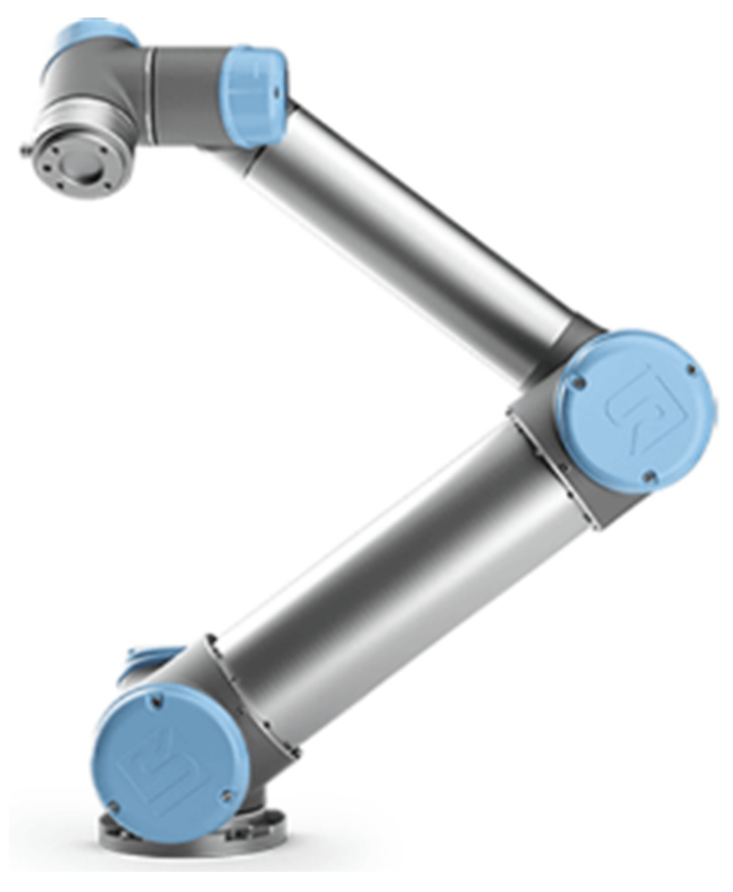
Figure 1. UR5 Robotic arm.
Mathematics 10 04835 g001
Figure 2. Type-2 triangular membership functions with 20% lower lag and 20% scale uncertainty.
Mathematics 10 04835 g002
Figure 3. Structure of an IT2FLS.
Mathematics 10 04835 g003
Figure 4. FSMC and T2FSMC with adaptive control gains of Γ.
Mathematics 10 04835 g004
Figure 5. Input membership functions of the fuzzy type-2 systems with 20% lower lag uncertainty.
Mathematics 10 04835 g005
Figure 6. FSMC and T2FSMC with variable of α.
Mathematics 10 04835 g006
Figure 7. FSMC with α and Γ.
Mathematics 10 04835 g007
Figure 8. Predefined fuzzy type-2 output membership functions of the controller gains of Γ.
Mathematics 10 04835 g008
Figure 9. Tuned fuzzy type-2 output membership functions of gains of Γ.
Mathematics 10 04835 g009
Figure 10. Predefined fuzzy type-2 output membership functions of the controller gains of α.
Mathematics 10 04835 g010
Figure 11. Tuned fuzzy type-2 output membership functions of the controller gains of α.
Mathematics 10 04835 g011
Figure 12. Best value of Γ fuzzy rule tuning.
Mathematics 10 04835 g012
Figure 13. Best value of α fuzzy type 2 tuning.
Mathematics 10 04835 g013
Figure 14. Best value of α fuzzy type-1 tuning.
Mathematics 10 04835 g014
Figure 15. Best value of α fuzzy type-2 tuning.
Mathematics 10 04835 g015
Figure 16. Surface of tuned Γ fuzzy type-1 system.
Mathematics 10 04835 g016
Figure 17. Surface of tuned Γ fuzzy type-2 system.
Mathematics 10 04835 g017
Figure 18. Surface of tuned α fuzzy type-1 system.
Mathematics 10 04835 g018
Figure 19. Surface of tuned α fuzzy type-2 system.
Mathematics 10 04835 g019
Figure 20. Applied input disturbances.
Mathematics 10 04835 g020
Figure 21. Trajectory tracking in first joint using Γ fuzzy systems.
Mathematics 10 04835 g021
Figure 22. Trajectory tracking in second joint using Γ fuzzy systems.
Mathematics 10 04835 g022
Figure 23. Trajectory tracking in third joint using Γ fuzzy systems.
Mathematics 10 04835 g023
Figure 24. Trajectory tracking in fourth joint using Γ fuzzy systems.
Mathematics 10 04835 g024
Figure 25. Trajectory tracking in fifth joint using Γ fuzzy systems.
Mathematics 10 04835 g025
Figure 26. Trajectory tracking in sixth joint using Γ fuzzy systems.
Mathematics 10 04835 g026
Figure 27. Trajectory tracking in first joint using α fuzzy systems.
Mathematics 10 04835 g027
Figure 28. Trajectory tracking in second joint using α fuzzy systems.
Mathematics 10 04835 g028
Figure 29. Trajectory tracking in third joint using α fuzzy systems.
Mathematics 10 04835 g029
Figure 30. Trajectory tracking in fourth joint using α fuzzy systems.
Mathematics 10 04835 g030
Figure 31. Trajectory tracking in fifth joint using α fuzzy systems.
Mathematics 10 04835 g031
Figure 32. Trajectory tracking in sixth joint using α fuzzy systems.
Mathematics 10 04835 g032
Figure 33. Trajectory tracking in first joint using αΓ fuzzy systems.
Mathematics 10 04835 g033
Figure 34. Trajectory tracking in second joint using αΓ fuzzy systems.
Mathematics 10 04835 g034
Figure 35. Trajectory tracking in third joint using αΓ fuzzy systems.
Mathematics 10 04835 g035
Figure 36. Trajectory tracking in fourth joint using αΓ fuzzy systems.
Mathematics 10 04835 g036
Figure 37. Trajectory tracking in fifth joint using αΓ fuzzy systems.
Mathematics 10 04835 g037
Figure 38. Trajectory tracking in sixth joint using αΓ fuzzy systems.
Mathematics 10 04835 g038
Figure 39. Velocity tracking in first joint using Γ fuzzy systems.
Mathematics 10 04835 g039
Figure 40. Velocity tracking in second joint using Γ fuzzy systems.
Mathematics 10 04835 g040
Figure 41. Velocity tracking in third joint using Γ fuzzy systems.
Mathematics 10 04835 g041
Figure 42. Velocity tracking in fourth joint using Γ fuzzy systems.
Mathematics 10 04835 g042
Figure 43. Velocity tracking in fifth joint using Γ fuzzy systems.
Mathematics 10 04835 g043
Figure 44. Velocity tracking in sixth joint using Γ fuzzy systems.
Mathematics 10 04835 g044
Figure 45. Velocity tracking in first joint using α fuzzy systems.
Mathematics 10 04835 g045
Figure 46. Velocity tracking in second joint using α fuzzy systems.
Mathematics 10 04835 g046
Figure 47. Velocity tracking in third joint using α fuzzy systems.
Mathematics 10 04835 g047
Figure 48. Velocity tracking in fourth joint using α fuzzy systems.
Mathematics 10 04835 g048
Figure 49. Velocity tracking in fifth joint using α fuzzy systems.
Mathematics 10 04835 g049
Figure 50. Velocity tracking in sixth joint using α fuzzy systems.
Mathematics 10 04835 g050
Figure 51. Velocity tracking in first joint using αΓ fuzzy systems.
Mathematics 10 04835 g051
Figure 52. Velocity tracking in second joint using αΓ fuzzy systems.
Mathematics 10 04835 g052
Figure 53. Velocity tracking in third joint using αΓ fuzzy systems.
Mathematics 10 04835 g053
Figure 54. Velocity tracking in fourth joint using αΓ fuzzy systems.
Mathematics 10 04835 g054
Figure 55. Velocity tracking in fifth joint using αΓ fuzzy systems.
Mathematics 10 04835 g055
Figure 56. Velocity tracking in sixth joint using αΓ fuzzy systems.
Mathematics 10 04835 g056
Figure 57. Variation of Γ for Γ type-1 fuzzy system.
Mathematics 10 04835 g057
Figure 58. Variation of Γ for Γ type-2 fuzzy system.
Mathematics 10 04835 g058
Figure 59. Variation of α for α type-1 fuzzy system.
Mathematics 10 04835 g059
Figure 60. Variation of α for α type-2 fuzzy system.
Mathematics 10 04835 g060
Figure 61. Variation of Γ for αΓ type-1 fuzzy system.
Mathematics 10 04835 g061
Figure 62. Variation of Γ for αΓ type-2 fuzzy system.
Mathematics 10 04835 g062
Figure 63. Variation of α for αΓ type-1 fuzzy system.
Mathematics 10 04835 g063
Figure 64. Variation of α for αΓ type-2 fuzzy system.
Mathematics 10 04835 g064
Figure 65. Input torque in first joint using Γ fuzzy system.
Mathematics 10 04835 g065
Figure 66. Input torque in second joint using Γ fuzzy system.
Mathematics 10 04835 g066
Figure 67. Input torque in third joint using Γ fuzzy system.
Mathematics 10 04835 g067
Figure 68. Input torque in fourth joint using Γ fuzzy system.
Mathematics 10 04835 g068
Figure 69. Input torque in fifth joint using Γ fuzzy system.
Mathematics 10 04835 g069
Figure 70. Input torque in sixth joint using Γ fuzzy system.
Mathematics 10 04835 g070
Figure 71. Input torque in first joint using α fuzzy system.
Mathematics 10 04835 g071
Figure 72. Input torque in second joint using α fuzzy system.
Mathematics 10 04835 g072
Figure 73. Input torque in third joint using α fuzzy system.
Mathematics 10 04835 g073
Figure 74. Input torque in fourth joint using α fuzzy system.
Mathematics 10 04835 g074
Figure 75. Input torque in fifth joint using α fuzzy system.
Mathematics 10 04835 g075
Figure 76. Input torque in sixth joint using α fuzzy system.
Mathematics 10 04835 g076
Figure 77. Input torque in first joint using αΓ fuzzy system.
Mathematics 10 04835 g077
Figure 78. Input torque in second joint using αΓ fuzzy system.
Mathematics 10 04835 g078
Figure 79. Input torque in third joint using αΓ fuzzy system.
Mathematics 10 04835 g079
Figure 80. Input torque in fourth joint using αΓ fuzzy system.
Mathematics 10 04835 g080
Figure 81. Input torque in fifth joint using αΓ fuzzy system.
Mathematics 10 04835 g081
Figure 82. Input torque in sixth joint using αΓ fuzzy system.
Mathematics 10 04835 g082
Figure 83. Velocity tracking in first joint using Γ fuzzy systems.
Mathematics 10 04835 g083
Figure 84. Velocity tracking in second joint using Γ fuzzy systems.
Mathematics 10 04835 g084
Figure 85. Velocity tracking in third joint using Γ fuzzy systems.
Mathematics 10 04835 g085
Figure 86. Velocity tracking in fourth joint using Γ fuzzy systems.
Mathematics 10 04835 g086
Figure 87. Velocity tracking in fifth joint using Γ fuzzy systems.
Mathematics 10 04835 g087
Figure 88. Velocity tracking in sixth joint using Γ fuzzy systems.
Mathematics 10 04835 g088
Figure 89. Input torque in first joint using αΓ fuzzy system.
Mathematics 10 04835 g089
Figure 90. Input torque in second joint using αΓ fuzzy system.
Mathematics 10 04835 g090
Figure 91. Input torque in third joint using αΓ fuzzy system.
Mathematics 10 04835 g091
Figure 92. Input torque in fifth joint using αΓ fuzzy system.
Mathematics 10 04835 g092
Figure 93. Input torque in sixth joint using αΓ fuzzy system.
Mathematics 10 04835 g093
Table 1. Fuzzy type-1 tuned rules for Γ .
Γ e ˙
NBNSZPSPB
e NBVBVSBBB
NSSMVSVBB
ZSBVBBB
PSMVSVSSM
PBVBMBVSM
Table 2. Fuzzy type-2 tuned rules for Γ .
Γ e ˙
NBNSZPSPB
e NBSMVBSM
NSMMMBB
ZVSBVBVSS
PSBMMBS
PBBBVBBS
Table 3. Fuzzy type-1 tuned rules for α .
α e ˙
NBNSZPSPB
e NBVSBSSM
NSBVSSSVB
ZVBVSSBM
PSVBBBMB
PBBMMVBM
Table 4. Fuzzy type-2 tuned rules for α .
α e ˙
NBNSZPSPB
e NBBSBVBS
NSMVSVSVSB
ZSMVSBVS
PSSBBVSS
PBSVBSSM
Table 5. Fuzzy type-2 tuned output MF parameters for Γ .
MFScaleLower Lag
Initial ValueTunned ValueInitial ValueTunned Value
NB0.80.80000.20.2399
NS0.80.91330.20.2691
Z0.80.40760.20.1971
PS0.80.53580.20.8950
PB0.80.76890.20.1536
Table 6. Fuzzy type-2 tuned output MF parameters for α .
MFScaleLower Lag
Initial ValueTunned ValueInitial ValueTunned Value
NB0.80.80030.20.9133
NS0.80.03770.20.0527
Z0.80.47140.20.8419
PS0.80.57370.20.3308
PB0.80.32880.20.6841
Publisher’s Note: MDPI stays neutral with regard to jurisdictional claims in published maps and institutional affiliations.