Abstract
Thermal performance and phase-change dynamics in a channel having a cavity equipped with a heater and phase-change material (PCM)-packed bed (PB) region are analyzed during nanoliquid convection under an inclined magnetic field. Curvature of the upper wall above the PCM zone is also considered by using the finite element method. Impacts of curvature of the upper wall (between 0.01H and 0.6H, H-channel height), strength of magnetic field (MGF) (Hartmann number between 0 and 40), height (between 0.1H and 0.4H) and number (between 5 and 17) of heaters on the thermal performance and phase-change dynamics are studied. In the interior and wall near regions of the PCM-PB, the curvature effects become opposite, while phase completion time (tF) rises by about 42% at the highest radius of the curvature. Imposing MGF and increasing its strength has positive impacts on the phase change and thermal performance. There is a reduction in tF by about and when MGF is imposed at Ha = 40 for pure fluids and nanofluids. When thermal performance for all different cases is compared, using MGF+nanofluid+PCM provides the most favorable case. When the reference case (only pure fluid without MGF and PCM) is used, including nanoparticles results in an improvement of 33.7%m while it is further increased to 71.1% when PCM-PB is also installed. The most favorable case by using MGF, nanofluid and PCM-PB results in thermal performance improvement of about 373.9% as compared to the reference configuration.
MSC:
76D25; 76D55; 80M10; 80M50; 76S05
1. Introduction
Energy management and storage are two main topics that have been studied extensively in recent years. Due to the rising concerns about energy costs and environmental impacts, alternative design solutions for energy-efficient products are developed, tested and offered for a variety of applications in thermal science. In electronic cooling, a large amount of produced heat in a limited space should be removed as fast as possible for operation safety and increasing the life-span of products [1,2]. Flow in channels with area expansion/contraction have been considered in many studies, while important features of the flow have been identified [3,4]. Separated flow characteristics over facing steps (backward-BFS, forward-FFS) or channels involving cavities combined with heat transfer (HT) are relevant in many types of HT equipment involving electronic cooling applications or cooling systems for batteries. A comprehensive review of convective HT with separated flow features has been given in Ref. [5]. The authors of this study considered different studies for separation/reattachment, while many control methods have been summarized from multi-disciplinary works. They noted that the channel expansion ratio is important for the size of the basic recirculation, while other coupled effects will shape the characteristics after the step. The flow and HT features in a channel with a change in area or the installation of cavities can be controlled by using diverse HT enhancement techniques, such as using fins, stationary/rotating objects, porous obstacles, flow pulsations, and geometric forms of the walls. The inclination of the walls for convective flow over BFS has been considered in Ref. [6], where a step inclination between 15 and 90 was used. The highest Nusselt number (Nu) on the stepped wall was found near the side wall for an inclination greater than 30, while it appeared near the duct center for small inclinations. Abu-Mulaweh et al. [7] analyzed the mixed convection over inclined BFS while temperature and velocity distributions were found by using the cold wire anemometer and laser-Doppler velocimeter. They considered an inclination of the wall between 30 and 90. They noted significant impacts of inclination on the temperature distribution, while the local Nu was reduced with higher inclination angles from the vertical. Some other works that considered the curvature and inclination of the walls for convective HT over BFS can be found in Refs. [8,9,10,11].
Phase-change materials (PCMs) are commonly used in energy system applications for thermal management and energy storage purposes [12,13,14]. Some application examples include solar power, building energy and various HT equipments [15,16,17]. To increase the effectiveness of using PCMs in energy systems, many different methods have been proposed. As the lower thermal conductivity of PCM is a challenge, they are used with various techniques such as conductive fins, metal foams and nano-powders [18,19,20,21]. The PCM packed-bed (PB) systems have been considered in air conditioners, waste heat recovery applications, solar power and many more applications [22,23]. de Gracia and Cabeza [24] presented a comprehensive review of the characteristic features and important design parameters of PCM-PB systems. The geometric form of the system where the PCM-PB is equipped and other operating parameters are important for increasing the effectiveness of using PCM in HT equipments. Magnetic field (MGF) effects can be used with PCM applications. The MGF effects are relevant in diverse technologies, including medical technologies, micro-fluidic devices, micro-pumps, coolers of nuclear reactors, cooling and energy extraction [25,26,27]. In HT applications, MGF effects have been used for the control of HT and flow features [28,29,30]. In separated flow, the favorable features of using MGF have been shown in many studies, including flow over BFS/FFS geometries [30,31]. Sheikholeslami and Mahian [32] used MGF effects in a storage system equipped with nano-enhanced PCM. They performed numerical work by using the finite element method (FEM). They noted that employing MGF was an effective method for accelerating the phase change in an energy storage system. Kohyani et al. [33] employed MGF in a square porous enclosure for the phase changing of cyclohexane-copper nano-PCM. They observed that when intensive MGF was imposed, melting time was reduced, and the characteristics of melting line curvatures varied. In a recent work, Ghachem et al. [34], MGF effects were used with rotations for a PCM-PB-filled enclosure. The MGF strength has been imposed for the Hartmann values in the range of 0 and 30. Favorable impacts of using MGF on the acceleration of the phase-change process were noted. The MGF effects can be combined with effects of using nanoparticles in a base fluid for PCM applications. Nanofluid technology has been used in diverse energy systems to improve the thermal efficiency and provide effective thermal management [35,36,37,38]. Over the years, many nanoparticle types have been developed with advanced simulation tools for predicting the nanofluid behavior in thermal systems. When PCM applications are considered, the nanofluid technology has been successfully implemented, and favorable impacts of using nanopowders on the phase-changing process have been reported in many studies [39,40,41,42]. Rostami et al. [43] presented a comprehensive review for the HT and phase-change process using PCM and nano-PCMS by considering many different experimental and numerical models in convection and in energy storage. They noted that those materials improve the thermal efficiency, while some challenges still exist for commercialization and standardization. The particle type, its amount in the base fluid, HT fluid type, particle shape and size are some of the influential parameters for increasing the performance of PCMs in thermal systems. The effectiveness of using MGF in PCM-equipped systems has been further boosted by using nanopowders [44,45,46].
In the current study, the combined effects of using MGF and PCM-PB during nanofluid convection for a channel equipped with heater in a cavity within the channel on the phase transition and thermal performance are analyzed. A uniform MGF is used throughout the domain, while the upper channel wall above the PCM is partly curved. The favorable impacts of using MGF on phase transition has been shown in the previous works, but the coupled effects of flow separation due to the upper wall curvature for a channel with area expansion with an inclined uniform MGF on the thermal performance and phase-change process have never been studied. Hybrid nanoparticles are used to further improve the effectiveness of using MGF and HT performance. Different cases of using only MGF, only pure fluid, nanofluid+MGF, nanofluid+PCM and nanofluid+PCM+MGF will be compared in terms of thermal performance enhancements. As has been mentioned above, PCM-PB is widely used in various HT systems where the geometric form of the applications is diverse, which also includes beneficial aspects in terms of system development and performance optimization for solar power, electronic cooling, heat exchangers in waste heat recovery and other HT equipments.
2. Computational Model
The impacts of using nanofluid and MGF on improvements in thermal performance and PC process dynamics in a channel equipped with a cavity and heater were analyzed during forced convection. A schematic view is given in Figure 1. A cavity was introduced in the channel with the distance L1 from the inlet while the heater was installed within this region. The channel, cavity and heater heights were H1 = H, H2 = H and h. The heater had N rectangular protruding elements, which occupied the length of L3 within the cavity. Above the heater, the PCM-PB region was used, which has a layer height of Hp. The PCM region contained spherical-shaped paraffin wax capsules of 20 mm diameter, while Table 1 gives the thermophysical properties. The porosity of this region was taken as 0.55. The upper part of the channel wall above the PCM region was curved with an elliptic shape. The radius in the major and minor axis were ac and bc, while the value of bc was varied during the study. At the inlet, the velocity was uniform, with a value of ui. The temperature of the fluid at the inlet was Ti, while the heater was a constant temperature, T = Th, as the HT fluid, pure water and hybrid nanofluid were used. The nanofluid contained Ag-MgO nanoparticles with SVF = . This nanofluid was used as experimental data for the thermo-physical properties (viscosity and thermal conductivity), which are available in Ref. [47]. A uniformly inclined MGF was used throughout the computational domain with an inclination of . For the nanofluid modeling, the single-phase approach is considered. Induced MGF effects and displacement currents were not considered, along with the natural convection, thermal radiation and viscous dissipation effects.
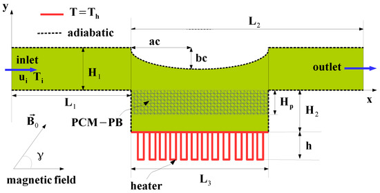
Figure 1.
Schematic view channel equipped with heater in a cavity and PCM-PB zone under uniform MGF.

Table 1.
Thermo-physical properties of PCM [48].
Conservation equations are given as [49,50]:
The Kozeny–Carmen model is used:
where take a value of 1 for the PCM region and take for the nanofluid region outside the PCM-PB region.
The conservation equation of energy for the PCM-PB region is considered with the following thermophysical properties [49]:
where takes 0 for and takes 1 for .
Among different phases, a non-equilibrum HT interface is considered. In this case, two equations are used with an additional source term as [51,52]:
where and represent the heat fluxes (conductive) of phases. The interstitial convective HT and source terms are given by the terms and Q. The definition of the related HT coefficient is [51,52]:
where is 10 (spherical particles). The fluid-to-solid Nu is described as [53]:
The Pr and Re are given as:
The fluid had uniform velocity (ui) and temperature (Ti) at the entrance. A pressure outlet was considered at the channel exit. The heater was isothermal with T = Th, while adiabatic () walls were used for the channel. An initial temperature of 303 K was considered. The relevant non-dimensional numbers were the Reynolds number () and the Hartmann number ().
For the solution of the governing equations, the finite element method (FEM) was utilized. The basic modeling steps in the FEM for HT and flow problems can be found in many sources [54,55,56]. FEM has been successfully used in thermal applications with PCM [57,58]. The relevant field variables are approximated using different ordered Lagrange FEs. When they are used in the equations, the residual (R) is formed, while its weighted average is set to be zero as [59]:
by using the weight function (W). The SUPG (streamline upwind Petrov–Galerkin) is used for numerical instability issues, while the BICGStab (biconjugate gradient stabilized) solver is utilized in the code. A convergence criteria of 10 is utilized by considering the second-order BDF (backward differentiation) for the time-dependent part. A commercial computational fluid dynamics code Comsol [52] is used.
Figure 2a shows the grid independence test results for phase transition time (tF) at two different MGF strengths. Grid G4 with 141,460 number of mixed (triangular+quadrilateral) elements was selected. The grid refinement locations are shown in Figure 2b. At the interfaces, near the walls of the channel and the heater, refinements were performed.
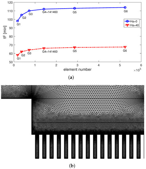
Figure 2.
Grid independence test results: phase transition time (tF in minutes) versus element number at two different MGF strengths (b = 0.4H, h = 0.25H, N = 12, SVF = 2%).
The validation of the code was conducted. In the first work, benchmark results were compared for the flow over BFS. The reattachment lengths at Re = 100 and for an expansion ratio of 2 were compared by using the works in Refs. [60,61,62]. Figure 3 shows the comparison of the reattachment lengths obtained from different sources. Deviations from the present solution are also given in the plot. The highest difference of 6.8% is seen with the result of [60], while a difference of less than 2% between the reattachment lengths is obtained when compared with the other cases. In another work, the results of Ghasemi et al. [63] are used. In this study, free convective HT in a square enclosure under MGF effects is analyzed. The cavity is differentially heated, where it is bounded by isothermal walls (hot and cold). In the work, Hartmann number values were considered between 0 and 60. Figure 4 shows the comparison results of flow and thermal pattern variations at a Hartmann number (Ha) of 30. It is seen that the flow and thermal behavior are captured well with the present solver. A comparison of the average Nu variation versus the Rayleigh number (Ra) is presented in Figure 5a at Ha = 30. The overall fits between the results are adequate. In another validation, experimental results from Ref. [64] were used, where phase-change dynamics in a differentially heated cavity are considered. A correlation for the solidified volume fraction in terms of Rayleigh number (Ra), dimensionless time () and cavity aspect ratio (AR) was derived. Figure 5b shows the comparison of the solidified volume fraction; the highest difference between the results is achieved at .
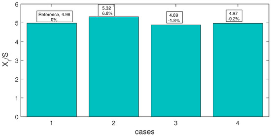
Figure 3.
Comparison of reattachment lengths in different benchmark studies at Re = 100 and expansion ratio of 2. Cases, C1: current study, C2: Ref. [60], C3: Ref. [61], C4: Ref. [62].
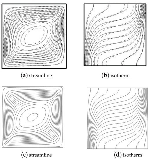
Figure 4.
Comparison of streamlines and isotherms for convection in a square cavity having two isothermal walls under MGF effects at Ha = 30 available in the study of Ghasemi et al. [63] (a,b) and in the present work (c,d).
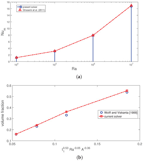
Figure 5.
Comparison of average Nu versus Rayleigh number (Ra) for convection in a square cavity having two isothermal walls under MGF effects at Ha = 30 as in Ref. [63] (a) and comparisons of the time-dependent volume fraction as in Ref. [64] (b).
3. Results and Discussion
Convective HT performance and PC process in an open cavity equipped with a PCM-PB region are analyzed under MGF when multiple heaters are used. Part of the cavity above the heaters is considered as curved, while the radius of the curvature is varied between 0.01H and 0.6H. A uniform MGF throughout the domain is considered for different strengths (Hartmann number values between 0 and 40). Heaters with different heights (between h = 0.1H and h = 0.4H) and different numbers (between N = 5 and N = 17) are used, while cases with PCM and without PCM considering pure fluid and nanofluid (SVF = 2%) as HT fluid are utilized. The Reynolds number is taken as Re = 300. Figure 6 shows the MGF strength impacts on the flow pattern distributions. In the absence of MGF (Ha = 0), a large recirculation region on the bottom wall of the channel after the heaters is established. Small vortices are also formed on the corners on the curved upper part of the open cavity. As the MGF is imposed and its magnitude is increased, suppression of those regions is observed due to the Lorentz force contributions in the momentum equations. Similar observations have been reported in the literature for vented cavity and for flow over BFS [8]. The PC process is also influenced by varying the MGF strength, as the vortex distribution and its variation extending the PB region are affected with the imposed MGF. Variations in the liquid fraction (L-FR) at different time instances are shown in Figure 7 considering different MGF strengths. In the regions of PCM closer to the walls, the L-FR amount is lower, while in the middle of this zone, the amount is higher. When MGF is imposed and its strength is increased, the PC process behavior in the interior domain and near the walls are altered. This is due to the fact that with higher MGF strength, the velocity is intensified near the wall regions, and the amount of L-FR increases. At t = 80 min, a complete phase transition is observed when MGF is imposed at Ha = 40. The acceleration of phase transitions with higher MGF strength has been reported in various studies [33,34].
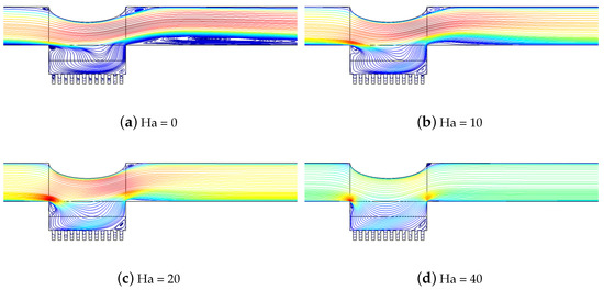
Figure 6.
Impacts of MGF strength on streamline distributions (bc = 0.4H, h = 0.25H, N = 13, SVF = 2%).
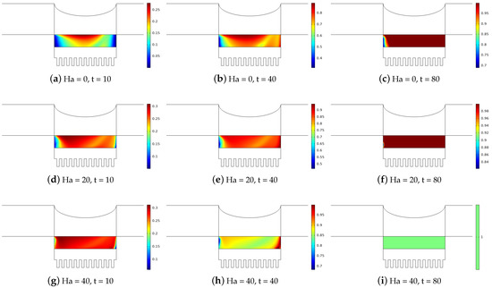
Figure 7.
Effects of MGF strength on liquid fraction (L-FR) distributions at different time instances (bc = 0.4H, h = 0.25H, N = 13, SVF = 2%).
The upper part of the channel above the heater is considered as curved, with a varying radius of the curvature between 0.01H and 0.6H. The flow field is influenced by the variation of the curvature, as shown in Figure 8. The case with a higher radius of the curvature leads to the formation of vortices on the upper-right corner of the curved region. At the higher value of b = 0.6H, recirculation regions are also formed on the left part of the PCM-installed zone and on the bottom wall of the channel after the heater as the fluid velocity rises due to the reduced passage area formed between the curved part and bottom wall. This also results in different characteristics of the PC process, as shown in Figure 9, considering different time instances. Due to the formation of the vortex near the left part of the PCM-PB zone, the amount of L-FR is lower at the highest b = 0.6H value in this region. In the interior of the PCM-PB region, the L-FR is higher due to the intensified fluid velocity as the passage area reduces with higher b values.
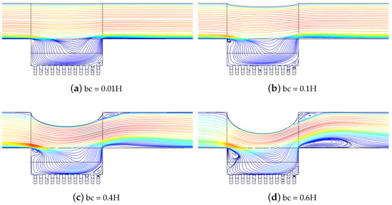
Figure 8.
Streamline distributions by varying the upper curved wall radius (Ha = 10, h = 0.25H, N = 13, SVF = 2%).
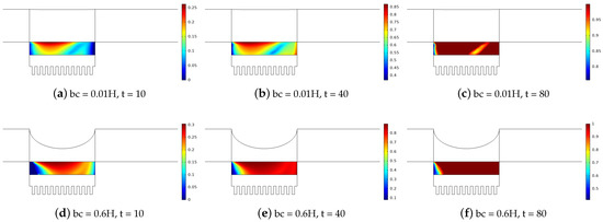
Figure 9.
Impacts of upper curved wall radius on the distributions of L-FR at various time instances (Ha = 10, h = 0.25H, N = 13, SVF = 2%).
Figure 10 shows the dynamic behavior of the PC process with varying MGF strengths and complete phase transition time (tF in minutes). When MGF is imposed, the process is accelerated, while at the same time, L-FR becomes higher with higher MGF strength. This is due to the vortex suppression and intensified velocity in the near-wall regions with higher MGF strength. When NF and PF are compared, both cases show a reduction in tF with higher MGF strength, but the values are lower when NF is used. This is attributed to the higher thermal transport features by using nanofluid in the PCM-PB zone. The reductions in tF are calculated as and by using PF and NF at the highest MGF strength as compared to the case at Ha = 0. Spatial average Nu comparisons for different cases of MGF strength by using PCM-PB are shown in Figure 11a. Higher MGF cases lead to higher values of Nu, which is due to the vortex suppression and intensified wall region velocity with MGF. When cases of using PCM-PB and without PCM-PB are compared under different MGF strengths, as shown in Figure 11b, significant improvement in the average Nu is seen when PCM-PB is used. Comparison results for spatial average Nu versus MGF strength for different cases of using PCM and NF are shown in Figure 11c. As the MGF strength is increased, average Nu values are increased for all cases. The most favorable case is obtained when PCM-PB is used with NF at the highest strength, while the lowest Nu is obtained in the absence of MGF for the PF case without PCM. At Ha = 0, between the cases of using PCM-NF and without PCM-PF, the average Nu rises by about , while it becomes when MGF is imposed at Ha = 40. Including nanofluid in the base fluid when PCM-PB region is installed results in an average Nu increment of 25% at Ha = 0 and 49.8% at Ha = 40.
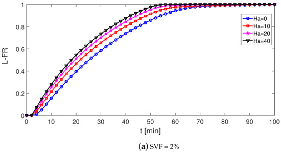
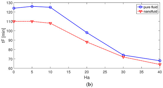
Figure 10.
Time-dependent variation in L-FR (a) and complete phase transition time (tF) at different MGF strengths (b) (bc = 0.4H, h = 0.25H, N = 13).
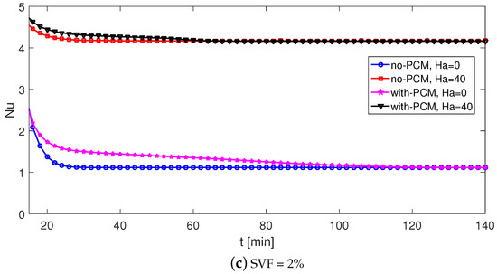
Figure 11.
Spatial average Nu versus Ha for different cases of using pure fluid, nanofluid and PCM (a); time-dependent variation of Nu for different MGF strengths by using nanofluid (b); time-dependent variation of Nu for different cases of using PCM with nanofluid (c) (bc = 0.4H, h = 0.25H, N = 13).
The flow dynamics and PC process are influenced by varying the curvature of the upper wall above the heater. Dynamic characteristics of L-FR for different radii of the curved wall are shown in Figure 12a. A higher value of radius (b) leads to higher L-FR until t = 70 min due to the increased fluid velocity, but after this time, the trend becomes the opposite, and the PC process becomes slower with higher radius values. This is due to the vortex formation in the PCM-PB zone with higher b values and inefficient phase transition near the wall regions, while in the interior of this zone fluid velocity rises. An efficient way to overcome this is to increase the MGF strength for the suppression of the vortex as shown before. The value of tF rises with a higher radius of the curved upper wall. The increment amounts are obtained as 45% and 42% for the PF and NF cases when the lowest and highest radius configurations are compared. The spatial average Nu rises with higher b values due to the increased fluid velocity over the heater, as shown in Figure 13. When the PCM-PB zone is installed in the system, further performance improvements can be achieved after some time. When different cases of using PCM and NF are compared, the highest average Nu is observed for the case with PCM+NF at b = 0.6H, while the lowest Nu is obtained for a flat upper wall when no PCM is used with PF. The average Nu increment becomes 83% and 47% when cases with the lowest and highest b are compared for NF+PCM and for PF without PCM. Along with the MGF, the curvature of the upper wall provides an excellent tool for HT and PC process control. The thermal performance of the heaters is shown to be influenced by using the PCM-PB region and varying MGF strength and upper wall curvature. The height and number of heaters are also influential on the thermal performance. When the height and number of heaters are increased, the spatial average Nu becomes lower (Figure 14). This can be attributed to the weak flow circulations within the narrow gaps forming the hot walls of the heater for higher height and numbers. When heater height is increased, the distance between the PCM-PB zone is reduced, while at the highest radius of the upper curved wall, the recirculation zone can be extended toward the left part of the heater, which leads to poor thermal performance characteristics.
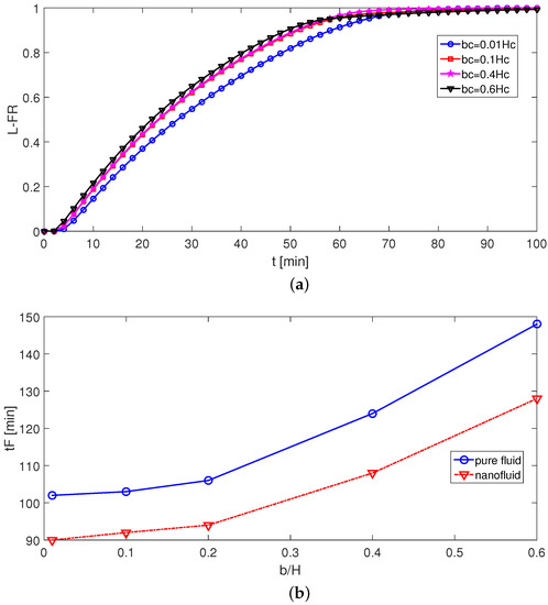
Figure 12.
Effects of upper curved-wall radius on the time-dependent variation of L-FR (a) and phase completion time (tF) (b) (Ha = 10, h = 0.25H, N = 13, SVF = 2%).
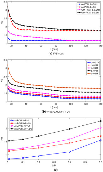
Figure 13.
Impacts of upper wall radius on the variation in time-dependent Nu for the cases with and without PCM (a), with PCM+nanofluid (b) and spatial average Nu for different cases of using PCM and nanofluid (c) (bc = 0.4H, Ha = 10, h = 0.25H, N = 13).
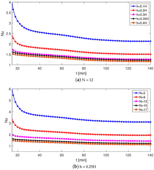
Figure 14.
Effects of heater size (a) and number (b) on the variation in the time-dependent spatial average Nu with PCM-PB system (bc = 0.4H, Ha = 10, SVF = 2%).
Figure 15 shows the comparison of different methods of HT enhancement by using nanofluid, MGF and PCM. As the reference case, pure fluid without MGF effects is considered, and average Nu increments are shown for different cases as compared to the reference configuration. By using nanofluid only, the spatial average Nu rises by about 33.7%, while this amount is further increased to 71.1% when PCB-PB is utilized. However, imposing MGF with the nanofluid significantly increases the average Nu up to 358.6%. When the PCM-PB system is installed for the nanofluid+MGF case, the amount becomes 373.9%. Imposing MGF with nanofluid provides the highest HT enhancement, while using PCM further improves the thermal performance, which is 37.4% in the absence of MGF (Ha = 0) and 15.3% in the presence of MGF at the highest strength (Ha = 40). Using nanofluid with MGF is effective on the thermal performance improvements and phase-change dynamics. By the combined utilization of MGF and nanoparticles, favorable impacts on the phase transition dynamics have been reported in several studies [45,46]. The reduction in the phase-change processing time depends upon the amount of nanoparticle loading, imposed MGF and other operating parameters. The wall region velocity intensification with imposed MGF will accelerate the phase-change process, while it also suppresses the vortexes within the cavity, which improves the HT. Including nano-sized particles in pure fluid improves the effectiveness of MGF and the phase-change process.
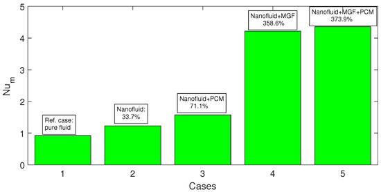
Figure 15.
Comparison of HT enhancement using different methods with nanofluid, PCM and MGF. Reference case is with the pure fluid configuration in the absence of MGF effects (Ha = 0) (bc = 0.4H, h = 0.25H, N = 13).
4. Conclusions
This study considers the convective HT and dynamics of the phase-change process in a channel having a cavity component equipped with encapsulated PCM and heater under inclined uniform MGF effects. Part of the wall above the PCM region is made corrugated, which has an elliptic shape. The following important conclusions can be drawn:
- The curvature of the upper wall results in altering the shape and size of vortex inside the PCM-PB region. In the interior and wall near regions, the amount of the L-FR shows opposite trends due to the enhanced velocity in the interior part. The phase completion time (tF) increases with higher curvatures of the upper wall. When the lowest- and highest-radius cases are compared, the increment amount of tF is obtained as 42%.
- MGF suppresses the vortices, and the velocity intensifies near the wall region. Therefore, the L-FR amount in those zones rises, and the phase-change process accelerates. The phase completion time (tF) is reduced by about and by using pure fluid (PF) and nanofluid (NF) at the highest strength of MGF as compared to cases without MGF.
- Average Nu rises by applying MGF and increasing its strength for configurations using PF and NF. The average Nu increment between the configurations with and without PCM-NF is obtained as at Ha = 40.
- In terms of thermal performance, the most favorable configuration is obtained when MGF with nanofluid is used for a PCM-PB equipped system. As compared to the reference case (only pure fluid without MGF and without PCM-PB), using NF only increases the HT by about 33.7%, and a further improvement of 71.1% is obtained when PCM-PB is installed. When MGF+NF+PCM is considered, the HT enhancement amount becomes 373.9% as compared to the reference configuration.
- Among using PCM, nanofluid and MGF, the highest impacts on the thermal performance improvement are obtained by using MGF. It also has profound impacts on the phase-change dynamics when PCM-PB is equipped.
The effects of pressure drop, entropy generation analysis, the impacts of the shapes of nanoparticles and two-phase modeling approaches can be considered along with different SVF of nanoparticles, MGF inclination and porosity of the PCM-PB zone as some of the potential extensions of the current work. Different thermal boundary conditions, non-uniform MGF effects and different curvature forms of the wall can be considered, which will extend the applicability of the results. The outcomes will be helpful in the initial design, optimization and thermal management studies relevant to electronic cooling, heat exchangers and diverse HT equipment.
Author Contributions
Conceptualization, F.S.; methodology, F.S.; software, F.S.; validation, L.K.; formal analysis, F.S., W.A. and L.K.; investigation, F.S., L.K., W.A., T.A. and S.A. (Salem Algarni); writing—original draft preparation, F.S.; writing—review and editing, F.S., L.K., W.A., S.A. (Salem Algarni) and S.A. (Sultan Alshehery); visualization, F.S. and L.K.; supervision, F.S., T.A., S.A. (Salem Algarni), S.A. (Sultan Alshehery) and W.A. All authors have read and agreed to the published version of the manuscript.
Funding
The authors thankfully acknowledge the funding provided by Scientific Research Deanship, King Khalid University, Abha, Kingdom of Saudi Arabia, under grant number RGP.1/389/43.
Data Availability Statement
Not applicable.
Conflicts of Interest
The authors declare no conflict of interest.
Abbreviations
| a, b | radii of the curvature |
| B | magnetic field strength |
| h | heater height |
| Ha | Hartmann number |
| H | channel height |
| Hp | PCM-PB height |
| k | thermal conductivity |
| L | length |
| L | latent heat of fusion |
| L-FR | liquid fraction |
| n | normal vector |
| Nu | Nusselt number |
| p | pressure |
| Pr | Prandtl number |
| Re | Reynolds number |
| t | time |
| tF | phase transition time |
| T | temperature |
| T | melting temperature |
| u, v | velocity components |
| x, y | Cartesian coordinates |
| Greek Characters | |
| kinematic viscosity | |
| dynamic viscosity | |
| density | |
| inclination of magnetic field | |
| porosity | |
| permeability | |
| electrical conductivity | |
| Subscripts | |
| c | cold |
| h | hot |
| m | average |
| nf | nanofluid |
| p | solid particle |
| Abbreviations | |
| BFS | backward-facing step |
| FEM | finite element method |
| FFS | forward-facing step |
| HT | heat transfer |
| MGF | magnetic field |
| PC | phase change |
| PB | packed bed |
| PCM | phase-change material |
| SVF | solid volume fraction |
References
- Ali, H.M.; Saieed, A.; Pao, W.; Ali, M. Copper foam/PCMs based heat sinks: An experimental study for electronic cooling systems. Int. J. Heat Mass Transf. 2018, 127, 381–393. [Google Scholar]
- Saidina, D.; Abdullah, M.; Hussin, M. Metal oxide nanofluids in electronic cooling: A review. J. Mater. Sci. Mater. Electron. 2020, 31, 4381–4398. [Google Scholar] [CrossRef]
- Armaly, B.F.; Durst, F.; Pereier, J.C.F.; Schonung, B. Experimental and theoretical investigation of backward-facing step flow. J. Fluid Mech. 1983, 127, 473–496. [Google Scholar] [CrossRef]
- Nie, J.; Armaly, B. Convection in laminar three-dimensional separated flow. Int. J. Heat Mass Transf. 2004, 47, 5407–5416. [Google Scholar] [CrossRef]
- Chen, L.; Asai, K.; Nonomura, T.; Xi, G.; Liu, T. A review of backward-facing step (BFS) flow mechanisms, heat transfer and control. Therm. Sci. Eng. Prog. 2018, 6, 194–216. [Google Scholar] [CrossRef]
- Chen, Y.; Nie, J.; Hsieh, H.T.; Sun, L. Three-dimensional convection flow adjacent to inclined backward-facing step. Int. J. Heat Mass Transf. 2006, 49, 4795–4803. [Google Scholar] [CrossRef]
- Abu-Mulaweh, H.; Armaly, B.F.; Chen, T. Measurements of laminar mixed convection in boundary-layer flow over horizontal and inclined backward-facing steps. Int. J. Heat Mass Transf. 1993, 36, 1883–1895. [Google Scholar] [CrossRef]
- Selimefendigil, F.; Öztop, H.F. Effects of local curvature and magnetic field on forced convection in a layered partly porous channel with area expansion. Int. J. Mech. Sci. 2020, 179, 105696. [Google Scholar] [CrossRef]
- Atashafrooz, M. Influence of radiative heat transfer on the thermal characteristics of nanofluid flow over an inclined step in the presence of an axial magnetic field. J. Therm. Anal. Calorim. 2020, 139, 3345–3360. [Google Scholar] [CrossRef]
- Ansari, A.B.; Nassab, S. Study of laminar forced convection of radiating gas over an inclined backward facing step under bleeding condition using the blocked-off method. J. Heat Transf. 2011, 133, 072702. [Google Scholar] [CrossRef]
- Atashafrooz, M.; Nassab, S.G. Simulation of three-dimensional laminar forced convection flow of a radiating gas over an inclined backward-facing step in a duct under bleeding condition. Proc. Inst. Mech. Eng. Part C J. Mech. Eng. Sci. 2013, 227, 332–345. [Google Scholar] [CrossRef]
- Sadeghi, H.M.; Babayan, M.; Chamkha, A. Investigation of using multi-layer PCMs in the tubular heat exchanger with periodic heat transfer boundary condition. Int. J. Heat Mass Transf. 2020, 147, 118970. [Google Scholar] [CrossRef]
- Leong, K.Y.; Rahman, M.R.A.; Gurunathan, B.A. Nano-enhanced phase change materials: A review of thermo-physical properties, applications and challenges. J. Energy Storage 2019, 21, 18–31. [Google Scholar] [CrossRef]
- Bianco, V.; De Rosa, M.; Vafai, K. Phase-change materials for thermal management of electronic devices. Appl. Therm. Eng. 2022, 214, 118839. [Google Scholar] [CrossRef]
- Javadi, F.; Metselaar, H.; Ganesan, P. Performance improvement of solar thermal systems integrated with phase change materials (PCM), a review. Sol. Energy 2020, 206, 330–352. [Google Scholar] [CrossRef]
- Khan, M.M.A.; Ibrahim, N.I.; Mahbubul, I.; Ali, H.M.; Saidur, R.; Al-Sulaiman, F.A. Evaluation of solar collector designs with integrated latent heat thermal energy storage: A review. Sol. Energy 2018, 166, 334–350. [Google Scholar] [CrossRef]
- Bondareva, N.S.; Sheremet, M.A. Conjugate heat transfer in the PCM-based heat storage system with finned copper profile: Application in electronics cooling. Int. J. Heat Mass Transf. 2018, 124, 1275–1284. [Google Scholar] [CrossRef]
- Zhao, C.; Opolot, M.; Liu, M.; Bruno, F.; Mancin, S.; Hooman, K. Numerical study of melting performance enhancement for PCM in an annular enclosure with internal-external fins and metal foams. Int. J. Heat Mass Transf. 2020, 150, 119348. [Google Scholar] [CrossRef]
- Mat, S.; Al-Abidi, A.A.; Sopian, K.; Sulaiman, M.Y.; Mohammad, A.T. Enhance heat transfer for PCM melting in triplex tube with internal–external fins. Energy Convers. Manag. 2013, 74, 223–236. [Google Scholar] [CrossRef]
- Nawsud, Z.A.; Altouni, A.; Akhijahani, H.S.; Kargarsharifabad, H. A comprehensive review on the use of nano-fluids and nano-PCM in parabolic trough solar collectors (PTC). Sustain. Energy Technol. Assess. 2022, 51, 101889. [Google Scholar] [CrossRef]
- Kok, B. Examining effects of special heat transfer fins designed for the melting process of PCM and Nano-PCM. Appl. Therm. Eng. 2020, 170, 114989. [Google Scholar] [CrossRef]
- Singh, H.; Saini, R.; Saini, J. A review on packed bed solar energy storage systems. Renew. Sustain. Energy Rev. 2010, 14, 1059–1069. [Google Scholar] [CrossRef]
- Regin, A.F.; Solanki, S.; Saini, J. Heat transfer characteristics of thermal energy storage system using PCM capsules: A review. Renew. Sustain. Energy Rev. 2008, 12, 2438–2458. [Google Scholar] [CrossRef]
- de Gracia, A.; Cabeza, L.F. Numerical simulation of a PCM packed bed system: A review. Renew. Sustain. Energy Rev. 2017, 69, 1055–1063. [Google Scholar] [CrossRef]
- Abedini-Nassab, R.; Pouryosef Miandoab, M.; Şaşmaz, M. Microfluidic synthesis, control, and sensing of magnetic nanoparticles: A review. Micromachines 2021, 12, 768. [Google Scholar] [CrossRef]
- Roy, K.; Devi, P.; Kumar, P. Magnetic-field induced sustainable electrochemical energy harvesting and storage devices: Recent progress, opportunities, and future perspectives. Nano Energy 2021, 87, 106119. [Google Scholar] [CrossRef]
- Al-Habahbeh, O.; Al-Saqqa, M.; Safi, M.; Khater, T.A. Review of magnetohydrodynamic pump applications. Alex. Eng. J. 2016, 55, 1347–1358. [Google Scholar] [CrossRef]
- Giwa, S.; Sharifpur, M.; Ahmadi, M.; Meyer, J. A review of magnetic field influence on natural convection heat transfer performance of nanofluids in square cavities. J. Therm. Anal. Calorim. 2021, 145, 2581–2623. [Google Scholar] [CrossRef]
- Sheremet, M.A.; Oztop, H.; Pop, I. MHD natural convection in an inclined wavy cavity with corner heater filled with a nanofluid. J. Magn. Magn. Mater. 2016, 416, 37–47. [Google Scholar] [CrossRef]
- Ma, Y.; Mohebbi, R.; Rashidi, M.; Yang, Z. MHD convective heat transfer of Ag-MgO/water hybrid nanofluid in a channel with active heaters and coolers. Int. J. Heat Mass Transf. 2019, 137, 714–726. [Google Scholar] [CrossRef]
- Selimefendigil, F.; Öztop, H.F. Hydro-thermal performance of CNT nanofluid in double backward facing step with rotating tube bundle under magnetic field. Int. J. Mech. Sci. 2020, 185, 105876. [Google Scholar] [CrossRef]
- Sheikholeslami, M.; Mahian, O. Enhancement of PCM solidification using inorganic nanoparticles and an external magnetic field with application in energy storage systems. J. Clean. Prod. 2019, 215, 963–977. [Google Scholar] [CrossRef]
- Kohyani, M.T.; Ghasemi, B.; Raisi, A.; Aminossadati, S. Melting of cyclohexane–Cu nano-phase change material (nano-PCM) in porous medium under magnetic field. J. Taiwan Inst. Chem. Eng. 2017, 77, 142–151. [Google Scholar] [CrossRef]
- Ghachem, K.; Selimefendigil, F.; Öztop, H.F.; Almeshaal, M.; Alhadri, M.; Kolsi, L. Effects of magnetic field, binary particle loading and rotational conic surface on phase change process in a PCM filled cylinder. Case Stud. Therm. Eng. 2021, 28, 101456. [Google Scholar] [CrossRef]
- Kakaç, S.; Pramuanjaroenkij, A. Review of convective heat transfer enhancement with nanofluids. Int. J. Heat Mass Transf. 2009, 52, 3187–3196. [Google Scholar] [CrossRef]
- Mahian, O.; Bellos, E.; Markides, C.N.; Taylor, R.A.; Alagumalai, A.; Yang, L.; Qin, C.; Lee, B.J.; Ahmadi, G.; Safaei, M.R.; et al. Recent advances in using nanofluids in renewable energy systems and the environmental implications of their uptake. Nano Energy 2021, 86, 106069. [Google Scholar] [CrossRef]
- Sheikholeslami, M.; Farshad, S.A.; Ebrahimpour, Z.; Said, Z. Recent progress on flat plate solar collectors and photovoltaic systems in the presence of nanofluid: A review. J. Clean. Prod. 2021, 293, 126119. [Google Scholar] [CrossRef]
- Hamzat, A.K.; Omisanya, M.I.; Sahin, A.Z.; Oyetunji, O.R.; Olaitan, N.A. Application of nanofluid in solar energy harvesting devices: A comprehensive review. Energy Convers. Manag. 2022, 266, 115790. [Google Scholar] [CrossRef]
- Ghasemi, K.; Tasnim, S.; Mahmud, S. PCM, nano/microencapsulation and slurries: A review of fundamentals, categories, fabrication, numerical models and applications. Sustain. Energy Technol. Assess. 2022, 52, 102084. [Google Scholar] [CrossRef]
- Elarem, R.; Alqahtani, T.; Mellouli, S.; Aich, W.; Khedher, N.B.; Kolsi, L.; Jemni, A. Numerical study of an Evacuated Tube Solar Collector incorporating a Nano-PCM as a latent heat storage system. Case Stud. Therm. Eng. 2021, 24, 100859. [Google Scholar] [CrossRef]
- Karaağaç, M.O.; Ergün, A.; Ağbulut, Ü.; Gürel, A.E.; Ceylan, I. Experimental analysis of CPV/T solar dryer with nano-enhanced PCM and prediction of drying parameters using ANN and SVM algorithms. Sol. Energy 2021, 218, 57–67. [Google Scholar] [CrossRef]
- Iachachene, F.; Haddad, Z.; Arıcı, M.; Abu-Nada, E.; Sheremet, M.A. The effect of nano encapsulated phase change materials and nanoparticles on turbulent heat transport: A conical diffuser scenario. J. Energy Storage 2022, 52, 104703. [Google Scholar] [CrossRef]
- Rostami, S.; Afrand, M.; Shahsavar, A.; Sheikholeslami, M.; Kalbasi, R.; Aghakhani, S.; Shadloo, M.S.; Oztop, H.F. A review of melting and freezing processes of PCM/nano-PCM and their application in energy storage. Energy 2020, 211, 118698. [Google Scholar] [CrossRef]
- Izadi, M.; Hajjar, A.; Alshehri, H.M.; Sheremet, M.; Galal, A.M. Charging process of a partially heated trapezoidal thermal energy storage filled by nano-enhanced PCM using controlable uniform magnetic field. Int. Commun. Heat Mass Transf. 2022, 138, 106349. [Google Scholar] [CrossRef]
- Sheikholeslami, M. Numerical simulation for solidification in a LHTESS by means of nano-enhanced PCM. J. Taiwan Inst. Chem. Eng. 2018, 86, 25–41. [Google Scholar] [CrossRef]
- Selimefendigil, F.; Öztop, H.F. Impacts of using an elastic fin on the phase change process under magnetic field during hybrid nanoliquid convection through a PCM-packed bed system. Int. J. Mech. Sci. 2022, 216, 106958. [Google Scholar] [CrossRef]
- Esfe, M.H.; Arani, A.A.A.; Rezaie, M.; Yan, W.M.; Karimipour, A. Experimental determination of thermal conductivity and dynamic viscosity of Ag–MgO/water hybrid nanofluid. Int. Commun. Heat Mass Transf. 2015, 66, 189–195. [Google Scholar] [CrossRef]
- Nallusamy, N.; Sampath, S.; Velraj, R. Experimental investigation on a combined sensible and latent heat storage system integrated with constant/varying (solar) heat sources. Renew. Energy 2007, 32, 1206–1227. [Google Scholar] [CrossRef]
- Mohammadnejad, F.; Hossainpour, S. A CFD modeling and investigation of a packed bed of high temperature phase change materials (PCMs) with different layer configurations. J. Energy Storage 2020, 28, 101209. [Google Scholar] [CrossRef]
- Cimpean, D.; Sheremet, M.; Pop, I. Mixed convection of hybrid nanofluid in a porous trapezoidal chamber. Int. Commun. Heat Mass Transf. 2020, 116, 104627. [Google Scholar] [CrossRef]
- Nield, D.; Bejan, A. Convection in Porous Media, in Convection Heat Transfer; John Wiley & Sons, Inc.: Hoboken, NJ, USA, 2013. [Google Scholar]
- COMSOL AB. Comsol User’s Guide; COMSOL AB: Stockholm, Sweden, 2018. [Google Scholar]
- Wakao, N.; Kaguei, S.; Funazkri, T. Effect of fluid dispersion coefficients on particle-to-fluid heat transfer coefficients in packed beds: Correlation of Nusselt numbers. Chem. Eng. Sci. 1979, 34, 325–336. [Google Scholar] [CrossRef]
- Nithiarasu, P.; Lewis, R.W.; Seetharamu, K.N. Fundamentals of the Finite Element Method for Heat and Mass Transfer; John Wiley & Sons: New York, NY, USA, 2016. [Google Scholar]
- Lewis, R.W.; Nithiarasu, P.; Seetharamu, K.N. Fundamentals of the Finite Element Method for Heat and Fluid Flow; John Wiley & Sons: West Sussex, UK, 2004. [Google Scholar]
- Reddy, J.N.; Gartling, D.K. The Finite Element Method in Heat Transfer and Fluid Dynamics; CRC Press: Boca Raton, FL, USA, 2010. [Google Scholar]
- Selimefendigil, F.; Öztop, H.F. Mixed convection in a PCM filled cavity under the influence of a rotating cylinder. Sol. Energy 2020, 200, 61–75. [Google Scholar] [CrossRef]
- Ghalambaz, M.; Chamkha, A.J.; Wen, D. Natural convective flow and heat transfer of nano-encapsulated phase change materials (NEPCMs) in a cavity. Int. J. Heat Mass Transf. 2019, 138, 738–749. [Google Scholar] [CrossRef]
- Sathiyamoorthy, M.; Chamkha, A. Effect of magnetic field on natural convection flow in a liquid gallium filled square cavity for linearly heated side wall(s). Int. J. Therm. Sci. 2010, 49, 1856–1865. [Google Scholar] [CrossRef]
- Cochran, R.; Horstman, R.; Sun, Y.; Emery, A. Benchmark solution for a vertical, buoyancy-assisted laminar backward-facing step flow using finite element, finite volume and finite difference methods. ASME-Publ.-HTD 1993, 258, 37. [Google Scholar]
- Dyne, B.; Pepper, D.; Brueckner, F. Mixed convection in a vertical channel with a backward facing step: A benchmark problem. ASME-Publ.-HTD 1993, 258, 49. [Google Scholar]
- Acharya, S.; Dixit, G.; Hou, Q. Laminar mixed convection in a vertical channel with a backstep: A benchmark study. ASME-Publ.-HTD 1993, 258, 11. [Google Scholar]
- Ghasemi, B.; Aminossadati, S.; Raisi, A. Magnetic field effect on natural convection in a nanofluid-filled square enclosure. Int. J. Therm. Sci. 2011, 50, 1748–1756. [Google Scholar] [CrossRef]
- Wolff, F.; Viskanta, R. Solidification of a pure metal at a vertical wall in the presence of liquid superheat. Int. J. Heat Mass Transf. 1988, 31, 1735–1744. [Google Scholar] [CrossRef]


Publisher’s Note: MDPI stays neutral with regard to jurisdictional claims in published maps and institutional affiliations. |
© 2022 by the authors. Licensee MDPI, Basel, Switzerland. This article is an open access article distributed under the terms and conditions of the Creative Commons Attribution (CC BY) license (https://creativecommons.org/licenses/by/4.0/).