Abstract
For the mission requirement of collision-free asteroid landing with a given time of flight (TOF), a fast generation method of landing reachable domain based on section and expansion is proposed. First, to overcome the difficulties of trajectory optimization caused by anti-collision path constraints, a two-stage collision-free trajectory optimization model is used to improve the efficiency of trajectory optimization. Second, the velocity increment under a long TOF is analyzed to obtain the distribution law of the reachable domain affected by the TOF, and the generation problem of the reachable domain is transformed into the solution problem of the initial boundary and the continuous boundary. For the initial boundary, the section method is used to acquire a point on the boundary as the preliminary reachable domain boundary. The solution of continuous boundary is based on the initial boundary continuously expanding the section into the reachable domain until the boundary is continuous. Finally, the proposed method is applied to the asteroids 101955 Bennu and 2063 Bacchus. The simulation results show that this method can quickly and accurately obtain the reachable domain of collision-free asteroid landing in a given TOF and is applicable to different initial positions.
Keywords:
collision-free asteroid landing; given time of flight; reachable domain; section and expansion method; trajectory optimization MSC:
70F05
1. Introduction
Asteroid exploration is the main way to understand the formation and evolution of the solar system, which is of great significance to the development and utilization of space resources and the defense against asteroid impact threats [1,2,3]. Asteroid sample return missions have attracted the attention of space-faring powers, such as the ongoing OSIRIS-Rex mission [4] of the United States and the Japanese Hayabusa2 mission [5] that landed on the surface of the near-Earth asteroid Ryugu and has successfully sampled and returned. The landing of the spacecraft on the asteroid surface to collect the high-resolution data and soil samples is a crucial step of the asteroid sample return mission. In the OSIRIS-REx mission, in order to select the most suitable landing site, the ground personnel screened and compared four sampling areas on the surface of the asteroid Bennu. These landing sites are controllable within the landing range that the spacecraft can reach, so they can be regarded as feasible candidate landing sites [6]. Therefore, the generation and analysis of the reachable domain of the asteroid surface are of great significance in landing site selection and mission planning [7]. The reachable domain refers to the set of terminal positions that the spacecraft can reach under given initial conditions and constraints. At present, it is mainly obtained by solving a series of trajectory optimization problems [8]. Benito and Mease [9] defined the reachable set and the controllable set and introduced the calculation method. The reachable set is obtained by the grid detection method. By defining boundary constraints, control constraints, path constraints, and cost functions, a large number of trajectory optimization is performed according to the resolution of each mesh. Arslantaş and Oehlschlägel [10] used the optimization-based method to calculate the reachable set of nonlinear system dynamics with constraints, which was used in the terminal landing phase for the lunar mission. The state space is discretized by equidistant grid points, and a distance function is defined for each grid point as the objective function to solve the feasible trajectory. The above two methods [9,10] need a lot of time to solve the reachable domain. Chen and Qiao [11] used an improved method to solve the envelope of the reachable domain of spacecraft after a gravity-assist flyby. It is determined whether the reachable domain intersects with the orbit of a planet to indicate whether the spacecraft can fly over the planet. Lee and Hwang [12] proposed a new algorithm for calculating the reachable set of spacecraft relative motion with energy-limited low thrust. By deriving the analytical solution of the optimal control problem, and applying the ellipsoid approximation method, the inner and outer two ellipsoids approaching the exact boundary of the reachable set are obtained, which effectively solves the problem of large computational complexity in solving the reachable set. It should be noted that the application of the analytical solution is any relative dynamic model in which the transfer matrix is available and analytically integrable. The reachable domain can be used not only to solve reachable terminal positions but also to design the low-thrust trajectory. Kulumani and Lee [13] designed continuous low-thrust transfers between asteroid periodic orbits by using reachable sets generated on a lower dimensional Poincare surface. The calculation of the reachable set reduces the need to generate accurate initial guesses for optimization and only needs to select a trajectory with the smallest distance to the target from the reachable set as the optimal transfer trajectory.
At present, the existing generation methods of reachable domain mainly take Earth, Mars, and the moon as landing objects, and the relevant research on the landing reachable domain of asteroid surface is less [8]. Wen and Zeng [14] obtained the landing reachable domain of the hopping rover after one maneuver on the asteroid surface and when it naturally evolves to rest through numerical simulation. This is different from the case of solving the reachable domain of soft landing on the asteroid surface under thrust control in this study. Huang and Liang [8] proposed a reachable domain generation method based on a dynamic neighborhood search. Specifically, the optimization problem of the reachable domain is transformed into three subproblems: the calculation of the landing point with minimum fuel consumption, the calculation of the landing point when fuel is exhausted, and the dynamic neighborhood search for the reachable domain boundary. This method can obtain the landing reachable domain of the asteroid surface with high efficiency. However, the landing trajectory optimization process in this method [8] does not consider the anti-collision path constraint.
The choice of landing trajectory optimization method is important for solving the reachable domain. When the initial state of the spacecraft is known, it is necessary to quickly obtain the reachable domain on the asteroid surface in a given time of flight (TOF) before the powered descending. Therefore, it is necessary not only to optimize the solution method of the reachable domain but also to select an energy-efficient landing trajectory optimization method. In the existing research, the energy-optimal problem is mostly studied by the optimal control theory and has various applications. In the transport mission, the minimum-energy trajectory can maximize the energy efficiency of the transport [15]. For robots working in special environments, energy consumption must be considered in the design phase to ensure the completion of tasks. Energy consumption caused by both motion and communication belongs to the field of energy-optimal problems [16]. Additionally, it is important to minimize energy consumption and extend the network life cycle in wireless networks [17]. The optimal energy control problem is also widely studied in astrophysics. In recent years, fast trajectory optimization methods for collision-free asteroid landing in the gravitational field have been studied [18,19,20,21,22,23]. The algorithm based on convex optimization [18,19,20] has the problem that as the flight distance increases, the variables of the optimization model also increase significantly, resulting in the low efficiency of long-distance trajectory optimization [19]. The anti-collision path constraints [19,20] are expressed as the combined constraints of ellipsoid/sphere and glide slope. Zhang and Zhang [21] designed a saturated adaptive six-degree-of-freedom control law suitable for collision-free asteroid landing by separating the spacecraft from the asteroid using the designed curved surface to avoid collision. However, the control is not optimal. Zhu and Yang [22] proposed a new guidance method for avoiding danger by improving the artificial potential function and designed an anti-collision zone with continuity and rapid numerical change rate that can effectively prevent the spacecraft from falling into the local minimum area in complex terrain. The authors [23] proposed a new two-stage collision-free trajectory optimization method based on the indirect method by using the two-stage anti-collision path constraint composed of the ellipsoid and the glide slope [20] that can quickly generate the energy optimal trajectory. According to the anti-collision path constraint, the whole flight process is divided into the descent stage and the final landing stage, and the trajectory optimization problem is transformed into a two-stage energy optimal control problem with the given TOF. The approximate analytical solution of the initial costate [24] provides the guess of the initial costate for the trajectory optimization in the descent stage and directly serves as the initial costate of the final landing stage, which simplifies the complexity of the path constraint and improves the efficiency of trajectory optimization.
Before the powered descending, it is needed to generate and analyze the landing reachable domain with different flight times to determine whether the landing site can be reached. This requires trajectory optimization for all points on the asteroid surface, and every time the TOF is changed, the trajectory optimization of all surface points must be solved again, resulting in low efficiency. To this end, a method was proposed for quickly generating the landing reachable domain within a given TOF. To overcome the difficulty of landing trajectory optimization caused by anti-collision path constraints, a two-stage collision-free trajectory optimization method [23] was used to improve the efficiency and convergence of the optimization problem. Here, by analyzing the velocity increment under a long TOF, the distribution law of the reachable domain affected by TOF is obtained, so the generation of the reachable domain is simplified to the solution of the initial boundary and the continuous boundary. The initial boundary is defined as the boundary of the reachable domain preliminarily obtained by the section method. In view of the irregular shape of asteroids and the uneven gravitational field, the reachable domain usually presents a complex shape, and the boundary obtained by a one-time solution is usually difficult to clearly describe the boundary of the reachable domain. Therefore, it is proposed that the initial boundary is continuously extended to the interior of the reachable domain until the boundary is continuous to obtain the final continuous boundary. Finally, the proposed method is applied to the asteroids Bennu and Bacchus to verify the effectiveness and efficiency of the method.
2. Trajectory Optimization for Collision-Free Landing
2.1. Dynamic Models and Constraints
An asteroid-fixed coordinate system o-xyz with the mass center o of the asteroid as the coordinate origin is defined, of which the three axes are aligned with the three principle axes. Assume that asteroids uniformly rotate around the axis of maximum moment of inertia, and the motion equations of a spacecraft in the frame o-xyz are [24]
where r = [x, y, z]T is the position vector, v = [vx, vy, vz]T is the velocity vector, and m is the mass of the spacecraft system, respectively. Vector ω = [0, 0, ω]T is the angular velocity of the asteroid, g(r) is the gravitational acceleration, Tmax represents the maximum magnitude of the thrust, u ∈ [0, 1] is the thrust ratio, α is the direction of the thrust, Isp is the specific impulse, and g0 = 9.80665 m/s2 is the standard gravity.
Assume that the initial state vector of the spacecraft is known and expressed as
In this study, the reachable domain is defined as a set of points on the surface of an asteroid that can be reached. Based on the used polyhedron model, points on the surface of an asteroid are represented by the center of the surface triangle on the polyhedron, that is
where r1, r2, and r3 are three vertexes of a triangle, i stands for the i-th triangle, and Nf represents the total number of surface triangles of the selected polyhedral model. Then, for the soft landing problem with a given flight time tf, the final state vector of the spacecraft is known and written as
Due to the irregular gravity field and the rotation of the asteroid, it is necessary to set anti-collision path constraints to prevent the spacecraft from colliding with the asteroid’s surface during landing. The anti-collision path constraints are defined as the combination of external ellipsoid constraint and glide-slope constraint [20], which are respectively expressed as
where Re means diagonal matrix, with , and a, b and c are the semiaxis of the ellipsoid. Vector n is the outer normal vector of the triangle on the asteroid surface, and θ is the conical angle of the glide-slope constraint.
2.2. Two-Stage Simplified Method for Collision-Free Trajectory Optimization
In this study, the energy-optimal trajectory optimization problem for collision-free asteroid landing is considered, and the two-stage simplified solution method [23] proposed by authors in the previous research is used to solve this problem. In this method, the asteroid landing process is divided into the descent stage that satisfies the ellipsoid constraint and the final landing stage that flies in the ellipsoid and meets the glide-slope constraint. In the descent stage, the approximate initial costate of the generalized gravity-free energy-optimal control problem [24] is employed as the initial guess. In the final landing stage, the approximate analytical solution [24] can directly provide initial costate and the energy consumption for the optimal trajectories.
To plan the two-stage energy-optimal trajectory, the performance index is [23]
where J1 and J2 are the performance index of the energy-optimal control problem in the descent stage and the gravity-free energy-optimal control problem [24] in the final landing stage, respectively, λ0 = Tmax2/2m02 is a positive numerical factor that does not inherently change the optimal problem [25], m0 is the initial mass of the spacecraft, tp is the flight time of the descent stage, and a is the control acceleration of the final landing stage.
For the energy-optimal control problem in the descent stage, the costate λ(t) satisfies
where the costate λ(t) = [λr, λv, λm]T correspond to the state X(t) = [r, v, m]T. The optimal thrust direction α and the optimal thrust magnitude u are
where ρ is the switching function, expressed by
In addition, according to the transversality condition, the final mass costate of the descent stage can be written as
For the gravity-free energy-optimal control problem [24] in the final landing stage, the initial costate λ(t0) = [λr0, λv0, λm0] can be solved by
and the optimal-control acceleration a* is obtained as
where tpf is the flight time of the final landing stage, rp and vp are the final position and velocity of the descent stage, respectively. When rp and vp are determined, by solving Equations (13) and (14), the energy consumption J2 and initial costate of the final landing stage can be analytically obtained, while the trajectory is required to satisfy the glide-slope constraint given by Equation (6). Since the landing state and flight time are fixed, the trajectory only changes with rp and vp, i.e., the trajectory satisfying the glide-slope constraint can be obtained by changing rp and vp. In the descent stage, known the initial state in Equation (2) and flight time tp, if the initial costates of this stage are given, the trajectory and rp and vp can be obtained by integrating Equations (1) and (8), thereby generating the trajectory of the final landing stage by rp and vp. Under the conditions that the trajectory satisfies the path constraint of the descent stage, and rp and vp make the final landing stage satisfy the anti-collision path constraint, the initial costate that minimizes the energy consumption J of the two stages is found. Then, the problem can be solved.
The numerical integration method used above is the fourth-order Runge–Kutta algorithm with fixed step size. The optimal trajectories of anti-collision landing fulfill the following constraints: the dynamic constraints described by Equations (1), (8), and (13), initial-final state constraints described by Equations (2)–(4), anti-collision path constraints in Equations (5) and (6), the transversal condition described by Equation (12), and thrust magnitude constraint. The gradient descent method [26] is used to solve this problem, which can be performed by a nonlinear programming solver such as fmincon of the Matlab functions. Using the fmincon algorithm to solve this problem can be expressed as finding the initial costates that make the objective function, i.e., the two-stage energy consumption J, obtain the minimum value under the conditions of satisfying the above nonlinear inequality and equality constraints.
The feasibility of the trajectory optimization method depends on the error between the approximate analytical solution and the optimal solution in the final landing stage. The simulation results [23] show that the mean absolute error between them is less than 0.05, which means that the trajectories obtained by these two solutions are very close, and the convergence rate of the optimal trajectories can reach 96.4%. Because the anti-collision trajectory optimization problem has strong nonlinearity, compared with the traditional random guess method which is difficult to converge, the trajectory optimization algorithm has excellent performance.
3. Generation Method of the Reachable Domain
Through the above trajectory optimization method, the set of landing points with feasible solutions within a given TOF constitutes the landing reachable domain, which is expressed as Uc(tf). The obtained Uc(tf) is a set of terminal positions r(tf) satisfying constraints described in the previous section.
Solving times of feasible solution of landing trajectory depends on the number of surface triangles of the polyhedron model. The higher the model accuracy, the finer the division of surface triangles, that is, the more triangles, which leads to a large amount of computation and time-consuming to obtain the feasible solution of all surface points to obtain the reachable domain. To improve the efficiency of solving the reachable domain, this paper proposes to obtain the reachable domain boundary based on the distribution law of the reachable domain. The boundary roughly divides the asteroid surface into two parts with and without feasible solutions, and the former is the reachable domain of the required solution.
The reachable boundary is solved based on the section method and the expansion method. The section method is used to determine the rough boundary preliminarily. Since the boundary extracted by the section method is located at the edge of the reachable domain, it is difficult for the landing sites with the feasible solution to accurately describe the boundary contour. In order to improve the accuracy of the obtained reachable domain, an expansion method is proposed, that is, by expanding the initial boundary to the region with the feasible solution in the form of the section, the final continuous boundary is obtained. The method transforms the trajectory optimization problem of a large number of points in the region into that of a few points constituting the boundary, which avoids solving the feasible solutions of all points on the asteroid surface, and greatly reduces the amount of calculation on the premise of satisfying the high-precision solution of the reachable domain.
3.1. Initial Boundary of the Reachable Domain
The strategy of solving the boundary to obtain the reachable domain is based on the analysis of the distribution law of the reachable domain. By solving the distribution of the velocity increment of points with the feasible solution on the asteroid surface under the long TOF, the distribution law of the reachable domain affected by the TOF is obtained. The longer TOF is chosen to ensure that most of the points on the asteroid’s surface have feasible solutions. Velocity increment refers to the initial and final velocity variation of the landing trajectory with the feasible solution. It can be seen from Figure 1 that the velocity increment increases with the increase in the distance between the initial position and the landing site of the spacecraft. At the same time, the change in the velocity increment depends on the flight time; that is, when the flight time is short and it is difficult to reach a large velocity increment, it can be considered that the landing site in the region with large velocity increment does not have a feasible solution. Therefore, the numerical variation law of velocity increment can be regarded as the variation law of the asteroid surface region that the spacecraft can reach limited by the TOF. In Figure 1, taking Bacchus as an example, the distribution of the velocity increment of the spacecraft landing on the asteroid surface from different initial positions and the same longer TOF is described. The initial velocity of the spacecraft is assumed to be 0, and the black dot in the figure represents the initial position.

Figure 1.
Velocity increment distributions at different initial positions. (a) Over the North Pole. (b) Over the Equator. (c) Over the mid-latitude region.
According to the above analysis, it is concluded that the landing reachable domain increases with increasing flight time, and its distribution on the asteroid surface is closely related to the initial position of the spacecraft. The reachable domain boundary is determined by the position of any point on the boundary. Specifically, taking the distance from the point to the initial position as the radius, applying an upper and lower deviation to the radius to obtain a radius range, taking out the points on the asteroid surface within the radius range, and obtaining the reachable domain boundary by solving the feasible solution. At this time, the key to the problem is to determine the position of any point on the boundary.
Take out a group of asteroid surface points that change with the distance from the initial position, expressed as P(d), as shown by the yellow dot in Figure 2a. Then obtain a point on the reachable domain boundary by successively calculating the feasible solutions of these points. Since the reachable domain boundary refers to the edge of the region composed of the asteroid surface points with feasible solutions, the last point with feasible solutions in P(d) is the point on the boundary. In order to obtain uniformly and continuously distributed P(d), a plane section method is proposed that is defined as a method of obtaining two parallel planes after a plane is translated by the same distance along the normal vector of the plane in two opposite directions. The translation distance is determined by the size of the triangle on the asteroid surface and is generally taken as one half of the height h of the triangle to ensure the uniform and continuous distribution of points between the two planes. Thereby, the plane passes through the mass center of the asteroid, and the normal vector of the plane is perpendicular to the vector from the initial point to the mass center of the asteroid. As shown in Figure 2a, the two parallel planes are obtained by the plane section method, and the yellow dot between the planes is P(d). The points with feasible solutions in this group of points are shown as yellow “o” in Figure 2b. It should be pointed out that landing points with feasible but scattered solutions will be ignored when taking a point on the boundary. This is because the gravitational field near the asteroid is irregular, and the surface points of the asteroid with feasible solutions are not strictly within a certain region. Inevitably, some points fall outside the reachable domain obtained by the distribution law, and these points are scattered and small in number. Therefore, the scattered points are all ignored in this study. After removing the scattered points “o” in Figure 2b, the point “o” farthest from the initial position is a point on the boundary. The basis for determining whether a point is a scattered point is whether the distance between adjacent points exceeds 3h.
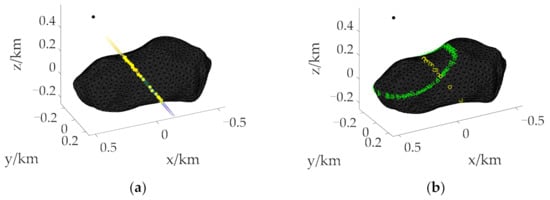
Figure 2.
Use of the section method. (a) Solving a point on the initial boundary by the section method. (b) A group of asteroid surface points used to solve the initial boundary. The yellow “o” stand for points with feasible solutions between parallel planes. The green “Δ“stand for points between parallel planes when solving initial boundary.
After determining a point on the boundary, the radius r0 is calculated, and the reachable domain boundary is obtained by using the circle section method, which is a method of obtaining the asteroid surface points between large and small radii by increasing and decreasing the radius by the same size. The size of increase and decrease is generally taken as one half of h, that is, the value range of radius r obtained is . This makes the number of points needed to solve the reachable domain boundary less and evenly distributed, and it greatly reduces the time consumption for solving the optimization problem. The obtained group of asteroid surface points is expressed as P(r), as shown by the green “Δ“ in Figure 2b. The reachable domain boundary can be obtained by taking out the points with feasible solutions.
However, since this group of points is located at the boundary between the points with feasible solutions and those without feasible solutions, the probability of occurrence of the two cases with and without feasible solutions is the same, which leads to the possibility that the points with feasible solutions may be discontinuous as the reachable domain boundary and the boundary description may not be clear. Discontinuity means that the distance between adjacent points is too large. In order to ensure computational efficiency and improve the accuracy of the boundary, the obtained boundary is defined as the initial boundary, and on this basis, the continuous boundary is obtained by extending to the region with the feasible solution.
3.2. Continuous Boundary of the Reachable Domain
The specific process of extending the initial boundary to the continuous boundary is as follows. First, the distance between adjacent points on the initial boundary is used to determine whether it is continuous. When the distance is less than 3h, it is continuous; otherwise, it is discontinuous. If any adjacent points are continuous, the initial boundary is the required final continuous boundary, and the reachable domain can be obtained. If it is not continuous, the extension method is used. Since the region composed of points with feasible solutions is the region close to the initial position in the two-part region divided by the boundary, the expansion method is to reduce the radius r to obtain a continuous boundary composed of points with feasible solutions.
The radius r1 is obtained by reducing r by h, and the value range obtained by the circular section method is , so as to obtain a group of asteroid surface points after the first expansion, expressed as P(r1). Points between all discontinuous points on the initial boundary are extracted from P(r1) along the vector direction from the asteroid centroid to the initial position. Through trajectory optimization, the obtained points with feasible solutions and the initial boundary form the boundary after the first expansion. Judge whether the boundary is continuous or not. If it is continuous, the final continuous boundary is obtained; otherwise, it continues to expand. The radius r2 is obtained by reducing r1 by h, and the value range obtained by using the circular section method is , so as to obtain a group of asteroid surface points P(r2) after the second expansion. The points between discontinuous points in the boundary are taken out along the vector direction. The obtained feasible solution and the boundary after the first expansion form the boundary after the second expansion. Repeat the above process until the obtained boundary is continuous. From the above expansion process, it can be seen that the height h of the triangle on the asteroid surface is taken as an expansion unit because this expansion unit can appropriately take out a layer of asteroid surface points, and its number and distribution state are the most suitable for solving the boundary.
Figure 3 shows the expansion process that the initial boundary is expanded twice to obtain a continuous boundary. In Figure 3a, “0” represents the initial boundary, and “1” and “2” represent the boundary obtained after the first and second expansion, respectively. Judging that “2” is a continuous boundary by the distance between adjacent points, the expansion stops and the reachable domain is obtained. Figure 3b highlights the specific expansion process of discontinuous adjacent points. Taking the extension of the “a” part with the discontinuous initial boundary as an example, after P(r1) is obtained, the points between green planes perpendicular to the paper surface are taken out according to the direction indicated by the arrow, and the points with feasible solutions form the boundary of this part. The direction indicated by the arrow is the vector direction from the mass center of the asteroid to the initial position. After determining the discontinuity of the “b” part in the boundary according to the distance, it continues to expand to obtain P(r2), and then takes out the points between red planes perpendicular to the paper according to the direction indicated by the arrow. At this time, the points with feasible solutions are continuous, and we can know that the continuous boundary of the “a” part is obtained after expanding it twice. The red dot in Figure 3b represents the points with the feasible solution obtained by trajectory optimization of all points on the asteroid surface.
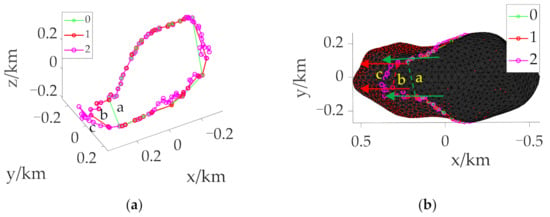
Figure 3.
Use of the extension method. (a) The extension from the initial boundary to the continuous boundary. (b) The extension of the “a” part. “0” represents the initial boundary, and “1” and “2” represent the boundary obtained after the first and second expansion, respectively.
4. Simulation Results and Analysis
The section and extension method is applied to obtain the reachable domain of the top-shaped asteroid Bennu and the elongated asteroid Bacchus to verify the effectiveness of the proposed method. All the simulations are implemented on a desktop computer with Intel Core i9-7920X CPU @2.90 GHz. To quickly calculate the gravitational field of the asteroids, the 2nd order spherical harmonic model and the rotating mass dipole model [27] be applied, respectively. For the spacecraft, the initial mass is 2000 kg, the maximum thrust Tmax = 20 N, the engine specific impulse Isp = 400 s, and the scaling is used, where the length scaling factor LU is set to 246 m and 1 km, respectively, and the time scaling factor s [24].
4.1. Applications to 101,955 Bennu
The rotation period of Bennu is 4.288 h and the average diameter is 492 m. A polyhedron model with 1348 vertices and 2692 faces is used in this paper. The number of faces is the number of target landing points. Taking energy optimization as the performance index, the trajectory optimization problem of collision-free asteroid landing is solved. 2692 trajectories need to be optimized when solving the landing reachable domain, which is extremely time-consuming. Therefore, the section and expansion method is used to obtain the boundary to improve the efficiency of the reachable domain under the given TOF. In order to fully reflect the effectiveness and applicability of the proposed reachable domain generation method, the initial positions of the spacecraft are selected to be above the North Pole, the Equator, and the mid-latitude region of the asteroid, which are [0 0 0.8] T km, [0.8 0 0] T km and [0.6 0 0.5] T km respectively. The initial velocity is set to 0 m/s.
4.1.1. Initial Boundary
The initial boundary is determined according to the distribution of velocity increment with a long TOF. As shown in Figure 4, the velocity increment distribution at different initial positions when tf = 1200 s and the TOF of the final landing stage is 200 s. It can be seen from the figure that at different initial positions, the velocity increment increases with the increase of the distance from the initial position. Therefore, the section method can be used to obtain a point on the initial boundary of the reachable domain.

Figure 4.
Distribution of velocity increment with different initial positions at tf = 1200 s. (a) Over the North Pole. (b) Over the Equator. (c) Over the mid-latitude region.
The process of taking a point on the boundary using the section method is shown by the yellow connecting line in Figure 5. Yellow “o” represents the points with feasible solutions between planes. After ignoring the scattered points, the remaining points are connected as lines. The far endpoint of the line relative to the initial position is the point on the initial boundary, and the distance from this point to the initial position is taken as the radius r0. Taking Figure 5a as an example, the radius r0 = 625 m, and the height h of the triangle on the asteroid surface is taken as 25 m. Using the circular section method, the surface points of the asteroid with a radius of more than 612.5 m but less than 637.5 m are taken out, and the points with feasible solutions form the initial boundary, as shown in green “o”. Figure 5a–f display the reachable domains of the asteroid surface at different initial positions when tf = 700 s and tf = 900 s. Among them, the purple dots indicate the points with feasible solutions obtained after trajectory optimization of all points on the asteroid surface, which are used as the references of the reachable domain to verify the effectiveness and accuracy of the reachable domain boundary solution.
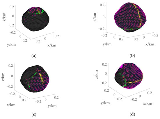
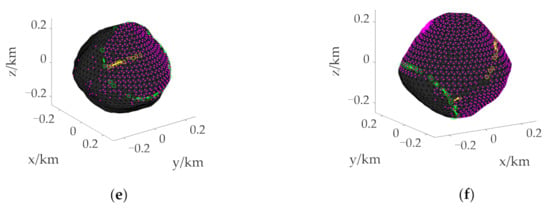
Figure 5.
Initial boundary of the reachable domain under different initial states. (a) Initial boundary for landing from over the North Pole with tf = 700 s. (b) Initial boundary for landing from over the North Pole with tf = 900 s. (c) Initial boundary for landing from over the Equator with tf = 700 s. (d) Initial boundary for landing from over the Equator with tf = 900 s. (e) Initial boundary for landing from over the mid-latitude region with when tf = 700 s. (f) Initial boundary for landing from over the mid-latitude region with when tf = 900 s. The yellow “o” stand for points with feasible solutions between parallel planes. The green “o” stand for points that make up the initial boundary. The purple dots indicate the points with feasible solutions on the asteroid surface.
It can be seen from Figure 5 that the range of the reachable domain is related to the initial position and the TOF of the spacecraft, and the proposed solution of the reachable domain can be applied to different situations. When the initial position is the same, the longer the given flight time, the larger the reachable range. In addition, Figure 5 shows that the initial boundary can effectively surround most of the purple points, and only a few scattered points are not within the boundary.
When tf = 900 s, histories of the position, velocity, mass, and descent trajectory of the energy optimal control problem landing on the asteroid surface from above the North Pole are shown in Figure 6. These results show that the two-stage simplified solution method based on the anti-collision path constraint enables the spacecraft to land safely at the target landing site. In the figure, the red “Δ“ and “●“ respectively indicate the transition position and landing position. In addition, the time consumption for solving an optimal landing trajectory is about 60 s.
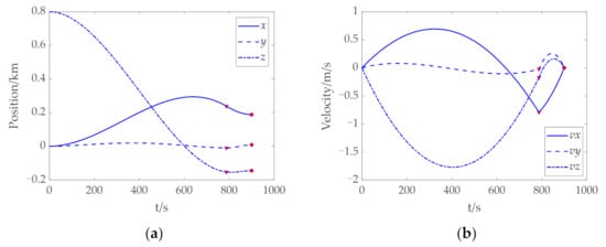
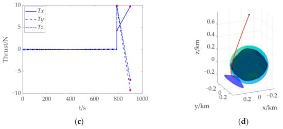
Figure 6.
Trajectory optimization results of landing on the asteroid Bennu from above the North Pole. (a) Histories of the position. (b) Histories of the velocity. (c) Histories of the thrust. (d) History of the descent trajectory. The red “Δ” and “●” indicate the transition position and landing position, respectively. “●” indicate the transition position and landing position, respectively.
4.1.2. Continuous Boundary
Based on the initial boundary obtained, judge whether it is continuous by the distance between adjacent points. When the distance is greater than 3h, i.e., 75 m, it is considered discontinuous, and the radius r needs to be reduced. Taking Figure 5a as an example, the radius r0 = 625 m at the initial boundary is obtained, and the radius r1 = r0 − h = 600 m after the first expansion. The surface point P(r1) of the asteroid after the first expansion is obtained using the circular section method. Along the vector direction from the asteroid centroid to the initial position, the points between all discontinuous points on the initial boundary are taken from P(r1) for trajectory optimization, and the obtained points with feasible solutions are connected with the initial boundary to become the boundary after the first expansion. Judge the distance of the boundary, repeat the above expansion process until the distance between all adjacent points is less than 75 m, and then obtain the final continuous boundary to determine the reachable domain.
Figure 7 shows the boundary at different initial positions when tf = 700 s, where the green connecting line represents the initial boundary, and the purple connecting line represents the continuous boundary. It can be seen that most of the initial boundary and the continuous boundary are coincident, and only when the distance between adjacent points is too large to describe the boundary is expansion required. In Figure 5, the initial boundary can basically surround the actual reachable domain, while the continuous boundary further improves the accuracy of the reachable domain boundary on the premise of a small increase in calculation.
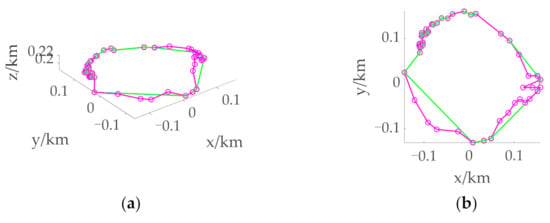
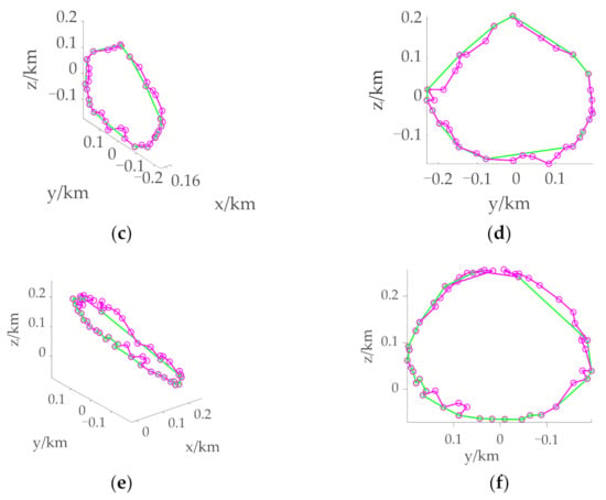
Figure 7.
Boundary of the reachable domain under different initial states with tf = 700 s. (a) 3D view of the boundary when the initial position is over the North Pole. (b) Supplementary view of the boundary when the initial position is over the North Pole. (c) 3D view of the boundary when the initial position is over the Equator. (d) Supplementary view of the boundary when the initial position is over the Equator. (e) 3D view of the boundary when the initial position is over the mid-latitude region. (f) Supplementary view of the boundary when the initial position is over the mid-latitude region. The green connecting line stands for the initial boundary. The purple connecting line stands for the continuous boundary.
In this study, considering the anti-collision path constraint and improving the trajectory optimization efficiency, the trajectory optimization methods used are two-stage simplified solutions [23]. Whether it is the traditional method of optimizing the trajectory of all points on the surface of the asteroid to obtain the reachable domain or the method of solving the boundary of the reachable domain proposed in this study, the time consumption for the trajectory optimization of a single point is basically the same. Therefore, the time-consuming ratio of the proposed method to the traditional method is approximated by comparing the number of points where the two methods need trajectory optimization, which illustrates the efficiency of trajectory optimization.
Table 1 lists the total number of points N of trajectory optimization required by the proposed method for obtaining a continuous boundary under different initial states, the total number of points Nf on the asteroid surface, and their ratio, i.e., the time-consuming ratio. In the table, P(d) represents the number of points needed for trajectory optimization when solving a point on the boundary; P(r) represents the number of points needed for trajectory optimization when solving the initial boundary; P(e) represents the number of points needed for trajectory optimization to obtain a continuous boundary by expanding the initial boundary and n represents the number of extension times.

Table 1.
Time-consuming statistics.
It can be seen that the ratio of N to Nf is not more than 6%, that is, the time-consuming ratio of the proposed method and the traditional method for solving the reachable domain is less than 6%. Therefore, the reachable domain solution method based on the section and expansion method proposed in this study can reduce the solution time by more than 94%, and greatly improve the solution efficiency. It should be pointed out that the use of the parfor greatly improves the efficiency of trajectory optimization.
We also verify that the more the number of faces on the surface of asteroid is, the smaller the time-consuming ratio is, and the advantages of the proposed method are more prominent. This is because the number of points taken by the section method for trajectory optimization can be determined manually, and the less the better under the condition of uniform and continuous distribution. Therefore, when the number of faces increases, the number of points in the section is almost unchanged, so the reduction of the time consumption ratio is the multiple of the increase of the number of faces.
4.2. Applications to 2063 Bacchus
In order to further prove the effectiveness of the proposed method, Bacchus was selected to solve the reachable domain. The rotation period of the asteroid is 14.9 h, and the polyhedron model with 2048 vertices and 4092 faces was adopted; that is, the number of triangle center points on the asteroid surface was 4092. Therefore, the number of trajectories that needed to be optimized with the two-stage simplified solution method was 4092. To further verify the effectiveness and applicability of the proposed method, it was also considered that the initial positions of the spacecraft are above the North Pole, the Equator, and the mid-latitude region of the asteroid, which were chosen as [0 0 0.6]T km, [1 0 0]T km and [0.4 0 0.6]T km, respectively. The initial velocity was set to 0 m/s.
4.2.1. Initial Boundary
The velocity increment of Bacchus at different initial positions when tf = 1600 s and the TOF of the final landing stage is 300 s is shown in Figure 1. It can be clearly seen that the velocity increment increases with the increase of the distance from the initial position. The process of obtaining a point on the initial boundary by using the section method is shown by the yellow connecting line in Figure 8, Figure 9 and Figure 10. The yellow “o” represents the point with the feasible solution in P®. After ignoring the scattered points, the yellow point “o” farthest from the initial position is the point on the initial boundary. Use this point to determine the radius to obtain the initial boundary, as shown by the green connecting line.
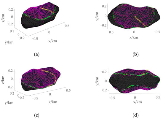
Figure 8.
Initial boundary when the initial position is above the North Pole. (a) 3D view of the initial boundary with tf = 900 s. (b) Supplementary view of the initial boundary with tf = 900 s. (c) 3D view of the initial boundary with tf = 1000 s. (d) Supplementary view of the initial boundary with tf = 1000 s. The yellow “o” stand for points with feasible solutions between parallel planes. The green “o” stand for points that make up the initial boundary. The purple dots indicate the points with feasible solutions on the asteroid surface.
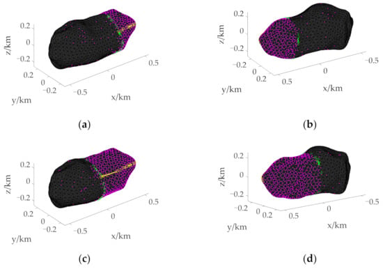
Figure 9.
Initial boundary when the initial position is above the Equator. (a) 3D view of the initial boundary with tf = 1000 s. (b) Supplementary view of the initial boundary with tf = 1000 s. (c) 3D view of the initial boundary with tf = 1100 s. (d) Supplementary view of the initial boundary with tf = 1100 s.
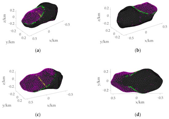
Figure 10.
Initial boundary when the initial position is above the mid-latitude region. (a) 3D view of the initial boundary with tf = 900 s. (b) Supplementary view of the initial boundary with tf = 900 s. (c) 3D view of the initial boundary with tf = 1000 s. (d) Supplementary view of the initial boundary with tf = 1000 s.
Taking Figure 8a as an example, the radius r0 and the height h of the triangle on the asteroid surface are taken as 620 m and 40 m, respectively. Using the circular section method, the asteroid surface points with radius r greater than 600 m but less than 640 m are extracted, and the initial boundary is obtained by trajectory optimization of these points. Figure 8, Figure 9 and Figure 10 show the initial boundaries of the reachable domain with different TOF when the initial positions of the spacecraft are over the North Pole, the Equator, and the mid-latitude region.
It can be seen from Figure 8, Figure 9 and Figure 10 that the reachable range is related to the initial position and the TOF of the spacecraft, and the proposed boundary method can be applied to different initial states. When the initial position is the same, the longer the given TOF, the larger the reachable range. The initial boundary can effectively surround most of the purple points, which further shows the effectiveness of the proposed method for solving the reachable domain boundary.
When tf = 1000 s, histories of the position, velocity, mass, and descent trajectory of the energy optimal control problem landing on the asteroid surface from above the North Pole are shown in Figure 11. These results show that the two-stage simplified solution method enables the spacecraft to land on the target point without collision. Similarly, the time consumption for solving an optimal landing trajectory is about 60 s.
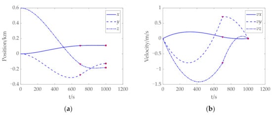
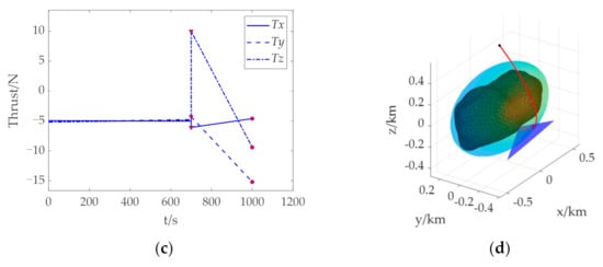
Figure 11.
Trajectory optimization results of landing on the asteroid Bacchus from above the North Pole. (a) Histories of the position. (b) Histories of the velocity. (c) Histories of the thrust. (d) History of the descent trajectory. The red “Δ“ and “●” indicate the transition position and landing position, respectively.
4.2.2. Continuous Boundary
Judge whether the distance between adjacent points meets the continuity condition based on the initial boundary, that is, when the distance between adjacent points is greater than 3h, i.e., 120 m, it is considered discontinuous. In this case, the radius r needs to be reduced. Taking Figure 12a as an example, when the initial boundary is obtained, the radius r0 = 620 m, and the radius r1 = r0 − h = 580 m after the first expansion. Based on r1, asteroid surface points P(r1) after the first expansion is obtained by using the circular section method. Along the vector direction from the asteroid centroid to the initial position, the points between all discontinuous points on the initial boundary are taken from P(r1) for trajectory optimization, and the obtained points with feasible solutions are connected with the initial boundary to become the boundary after the first expansion. Judge the distance of the boundary, repeat the above expansion process until the distance between all adjacent points is less than 120 m, and then obtain the final continuous boundary to determine the reachable domain.

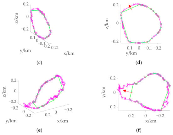
Figure 12.
Boundary of the reachable domain under different initial states with tf = 1000 s. (a) 3D view of the boundary when the initial position is over the North Pole. (b) Supplementary view of the boundary when the initial position is over the North Pole. (c) 3D view of the boundary when the initial position is over the Equator. (d) Supplementary view of the boundary when the initial position is over the Equator. (e) 3D view of the boundary when the initial position is over the mid-latitude region. (f) Supplementary view of the boundary when the initial position is over the mid-latitude region. The green connecting line stands for the initial boundary. The purple connecting line stands for the continuous boundary. The red arrow stands for the direction of expansion.
Figure 12 shows the boundary at different initial positions when tf = 1000 s, where the green connecting line represents the initial boundary and the purple connecting line represents the continuous boundary. It can be seen that most of the initial boundary and the continuous boundary are coincident, and only when the distance between adjacent points is too large to describe the boundary, expansion is required. From Figure 8, Figure 9 and Figure 10, it can be seen that the initial boundary can basically surround the actual reachable domain, while the continuous boundary further improves the accuracy of the reachable domain boundary on the premise of increasing a small amount of calculation. The expansion indicated by the red arrows in Figure 12d, f clearly illustrates the necessity of solving the continuous boundary.
Table 2 lists the total number of points N of trajectory optimization required for the proposed method to obtain the continuous boundary, the total number of points Nf on the asteroid surface, and their ratio, i.e., time-consuming ratio. It can be seen from Table 2 that the ratio of N to Nf is not more than 10%, that is, the time-consuming ratio of the proposed method and the traditional method to solve the reachable domain is less than 10%. Therefore, the reachable domain solution method based on the section and expansion method proposed in this study can reduce the solution time by more than 90%, and greatly improve the solution efficiency.

Table 2.
Time-consuming statistics.
5. Conclusions
In this paper, a fast generation method based on section and expansion is proposed to generate the reachable domain of collision-free asteroid landing with the given TOF. Considering the anti-collision requirements, a two-stage simplified solution method is used, which improves the efficiency and convergence of the trajectory optimization problem. By analyzing the velocity increment, the distribution law of the reachable domain is obtained. The generation problem of the reachable domain is transformed into three subproblems and solved in turn: the solution of a point on the initial boundary, the calculation of the initial boundary, and the calculation of the continuous boundary. The section and expansion method is used to solve these problems. Finally, the generation of the reachable domain on the asteroid surface is realized, and the efficiency of solving is greatly improved. Compared with the traversal algorithm, the time-consuming ratio is reduced by more than 90%. The effectiveness and applicability of the proposed method are verified by simulation analysis with asteroids of different shapes and spacecraft with different initial positions and different flight times.
Author Contributions
Conceptualization and methodology, Y.Z. and H.Y.; software, Y.Z. and J.H.; validation, Y.Z. and J.H.; formal analysis, Y.Z. and J.H.; writing—original draft preparation and supervision, Y.Z.; writing—review and editing, Y.Z. and H.Y.; visualization, Y.Z. All authors have read and agreed to the published version of the manuscript.
Funding
This research was funded by the National Natural Science Foundation of China under No. 12102177 and Natural Science Foundation of Jiangsu Province under No. BK20220130.
Institutional Review Board Statement
Not applicable.
Informed Consent Statement
Not applicable.
Data Availability Statement
All data generated or analyzed during this study are included in this published article in the form of figures and tables.
Conflicts of Interest
The authors declare no conflict of interest.
References
- Zhang, Y.; Michel, P. Shapes, structures, and evolution of small bodies. Astrodynamics 2021, 5, 293–329. [Google Scholar] [CrossRef]
- Zhang, Y.; Yu, Y.; Baoyin, H.X. Dynamical behavior of flexible net spacecraft for landing on asteroid. Astrodynamics 2021, 5, 249–261. [Google Scholar] [CrossRef]
- Zhang, X.; Luo, Y.; Xiao, Y.; Liu, D.; Guo, F.; Guo, Q. Developing Prototype Simulants for Surface Materials and Morphology of Near Earth Asteroid 2016 HO3. Space Sci. Technol. 2021, 2021, 9874929. [Google Scholar] [CrossRef]
- Rozitis, B.; Ryan, A.J.; Emery, J.P.; Nolan, M.C.; Green, S.F.; Christensen, P.R.; Lauretta, D.S. High-Resolution Thermophysical Analysis of the OSIRIS-REx Sample Site and Three Other Regions of Interest on Bennu. J. Geophys. Res. Planets 2022, 127, e2021JE007153. [Google Scholar] [CrossRef]
- Yada, T.; Abe, M.; Okada, T.; Nakato, A.; Yogata, K.; Miyazaki, A.; Hatakeda, K.; Kumagai, K.; Nishimura, M.; Hitomi, Y.; et al. Preliminary analysis of the Hayabusa2 samples returned from C-type asteroid Ryugu. Nat. Astron. 2021, 6, 214–220. [Google Scholar] [CrossRef]
- Ploen, S.R.; Seraji, H.; Kinney, C.E. Determination of spacecraft landing footprint for safe planetary landing. IEEE Trans. Aerosp. Electron. Syst. 2009, 45, 3–16. [Google Scholar] [CrossRef]
- Cui, P.; Ge, D.; Zhu, S.; Zhao, D. Research progress of autonomous planetary landing site assessment and selection. Sci. Sin. Technol. 2021, 51, 1315–1325. (In Chinese) [Google Scholar] [CrossRef]
- Huang, M.; Liang, Z.; Cui, P. Reachable zone generation for irregularly shaped asteroid landing. J. Astronaut. 2021, 42, 1550–1558. (In Chinese) [Google Scholar]
- Benito, J.; Mease, K.D. Reachable and controllable sets for planetary entry and landing. J. Guid. Control Dyn. 2010, 33, 641–654. [Google Scholar] [CrossRef]
- Arslantaş, Y.E.; Oehlschlägel, T.; Sagliano, M. Safe landing area determination for a moon lander by reachability analysis. Acta Astronaut. 2016, 128, 607–615. [Google Scholar] [CrossRef]
- Chen, Q.; Qiao, D.; Wen, C. Reachable domain of spacecraft after a gravity-assist flyby. J. Guid. Control Dyn. 2019, 42, 931–940. [Google Scholar] [CrossRef]
- Lee, S.; Hwang, I. Reachable set computation for spacecraft relative motion with energy-limited low-thrust. Aerosp. Sci. Technol. 2018, 77, 180–188. [Google Scholar] [CrossRef]
- Kulumani, S.; Lee, T. Low-thrust trajectory design using reachability sets near asteroid 4769 castalia. In Proceedings of the AIAA/AAS Astrodynamics Specialist Conference, Long Beach, CA, USA, 13–16 September 2016. [Google Scholar] [CrossRef][Green Version]
- Wen, T.; Zeng, X.; Circi, C.; Gao, Y. Hop reachable domain on irregularly shaped asteroids. J. Guid. Control Dyn. 2020, 43, 1269–1283. [Google Scholar] [CrossRef]
- Kim, H.; Kim, B. Energy-optimal transport trajectory planning and online trajectory modification for holonomic robots. Asian J. Control 2021, 23, 2185–2200. [Google Scholar] [CrossRef]
- Zhang, Y.; Wang, J.; Xu, Y.; Yang, D. Energy-optimal problem of multiple nonholonomic wheeled mobile robots via distributed event-triggered optimization algorithm. Chin. Phys. B 2019, 28, 030501. [Google Scholar] [CrossRef]
- Neely, M. Energy optimal control for time-varying wireless networks. IEEE Trans. Inf. Theory 2006, 52, 2915–2934. [Google Scholar] [CrossRef]
- Yang, H.; Bai, X.; Baoyin, H. Rapid generation of time-optimal trajectories for asteroid landing via convex optimization. J. Guid. Control Dyn. 2017, 40, 628–664. [Google Scholar] [CrossRef]
- Liu, X.; Yang, H.; Li, S. Collision-free trajectory design for long distance hopping transfer on asteroid surface using convex optimization. IEEE Trans. Aerosp. Electron. Syst. 2021, 57, 3071–3083. [Google Scholar] [CrossRef]
- Zhang, Y.; Huang, J.; Cui, H. Trajectory optimization for asteroid landing with two-phase free final time. Adv. Space Res. 2020, 65, 1210–1224. [Google Scholar] [CrossRef]
- Zhang, B.; Zhang, Y.; Bai, J. Twistor-Based Adaptive Pose Control of Spacecraft for Landing on an Asteroid with Collision Avoidance. IEEE Trans. Aerosp. Electron. Syst. 2021, 58, 152–167. [Google Scholar] [CrossRef]
- Zhu, S.; Yang, H.; Cui, P.; Xu, R.; Liang, Z. Anti-collision zone division based hazard avoidance guidance for asteroid landing with constant thrust. Acta Astronaut. 2022, 190, 377–387. [Google Scholar] [CrossRef]
- Zhao, Y.; Yang, H.; Li, S. Real-time trajectory optimization for collision-free asteroid landing based on deep neural networks. Adv. Space Res. 2022, 70, 112–124. [Google Scholar] [CrossRef]
- Yang, H.; Li, S.; Bai, X. Fast homotopy method for asteroid landing trajectory optimization using approximate initial costates. J. Guid. Control Dyn. 2019, 42, 585–597. [Google Scholar] [CrossRef]
- Jiang, F.; Baoyin, H.; Li, J. Practical techniques for low-thrust trajectory optimization with homotopic approach. J. Guid. Control Dyn. 2012, 35, 245–258. [Google Scholar] [CrossRef]
- Ma, H.; Xu, S. Optimization of bounded low-thrust rendezvous with terminal constraints by interval analysis. Aerosp. Sci. Technol. 2018, 79, 58–69. [Google Scholar] [CrossRef]
- Zeng, X.; Jiang, F.; Li, J.; Baoyin, H. Study on the connection between the rotating mass dipole and natural elongated bodies. Astrophys. Space Sci. 2015, 356, 29–42. [Google Scholar] [CrossRef]
Publisher’s Note: MDPI stays neutral with regard to jurisdictional claims in published maps and institutional affiliations. |
© 2022 by the authors. Licensee MDPI, Basel, Switzerland. This article is an open access article distributed under the terms and conditions of the Creative Commons Attribution (CC BY) license (https://creativecommons.org/licenses/by/4.0/).