Article

On Active Vibration Absorption in Motion Control of a Quadrotor UAV

1
Departamento de Energía, Universidad Autónoma Metropolitana, Unidad Azcapotzalco, Av. San Pablo No. 180, Col. Reynosa Tamaulipas, Mexico City 02200, Mexico
2
Departamento de Investigación, Tecnológico de Estudios Superiores de Tianguistenco, Santiago Tianguistenco 52650, Mexico
3
Departamento de Energía Eléctrica, Universidad Nacional Autónoma de México, Mexico City 04510, Mexico
4
Escuela de Ingeniería y Ciencias, Tecnologico de Monterrey, Av. Eugenio Garza Sada 2501, Monterrey 64849, Mexico
5
Facultad de Ingeniería, Universidad Panamericana, Álvaro del Portillo 49, Zapopan 45010, Mexico
*
Author to whom correspondence should be addressed.
Mathematics 2022, 10(2), 235; https://doi.org/10.3390/math10020235
Submission received: 27 October 2021 / Revised: 21 December 2021 / Accepted: 31 December 2021 / Published: 13 January 2022

Abstract

:
Conventional dynamic vibration absorbers are physical control devices designed to be coupled to flexible mechanical structures to be protected against undesirable forced vibrations. In this article, an approach to extend the capabilities of forced vibration suppression of the dynamic vibration absorbers into desired motion trajectory tracking control algorithms for a four-rotor unmanned aerial vehicle (UAV) is introduced. Nevertheless, additional physical control devices for mechanical vibration absorption are unnecessary in the proposed motion profile reference tracking control design perspective. A new dynamic control design approach for efficient tracking of desired motion profiles as well as for simultaneous active harmonic vibration absorption for a quadrotor helicopter is then proposed. In contrast to other control design methods, the presented motion tracking control scheme is based on the synthesis of multiple virtual (nonphysical) dynamic vibration absorbers. The mathematical structure of these physical mechanical devices, known as dynamic vibration absorbers, is properly exploited and extended for control synthesis for underactuated multiple-input multiple-output four-rotor nonlinear aerial dynamic systems. In this fashion, additional capabilities of active suppression of vibrating forces and torques can be achieved in specified motion directions on four-rotor helicopters. Moreover, since the dynamic vibration absorbers are designed to be virtual, these can be directly tuned for diverse operating conditions. In the present study, it is thus demonstrated that the mathematical structure of physical mechanical vibration absorbers can be extended for the design of active vibration control schemes for desired motion trajectory tracking tasks on four-rotor aerial vehicles subjected to adverse harmonic disturbances. The effectiveness of the presented novel design perspective of virtual dynamic vibration absorption schemes is proved by analytical and numerical results. Several operating case studies to stress the advantages to extend the undesirable vibration attenuation capabilities of the dynamic vibration absorbers into trajectory tracking control algorithms for nonlinear four-rotor helicopter systems are presented.

1. Introduction

Undesirable mechanical vibrations can be manifested in many engineering systems. Harmful vibrations could provoke several relevant troubles in mechanical structures such as rapid wear of machine parts, material fatigue, excessive noise, loss of efficiency, poor finishes of manufactured products, malfunction of instrumentation, discomfort to people, loosening of fasteners, and damage to property [1]. Forced harmonic vibrations can be induced by external oscillating disturbance forces or torques affecting the mechanical system dynamics. An alternative solution for unwanted vibration attenuation is the design of physical mechanical devices known as dynamic vibration absorbers. These vibration control devices are physically constituted by mechanical elements of inertia, stiffness, and damping [2]. Tuned mass damper, vibration neutralizer, anti-vibrator, dynamic damper, and shock absorber are some names commonly used in the literature to describe a dynamic vibration absorber as well [2,3,4]. These control devices are suitably tuned and coupled to mechanical structures (primary or main systems) to be protected against harmful forced harmonic vibrations. Since mechanical systems are prone to be excited at a specific frequency or subjected to multiple frequency excitations [5], diverse configurations for dynamic vibration absorbers have been proposed [2]. For the former case, passive vibration absorbers are tuned to efficiently suppress specific frequency harmonic excitations into an attenuation frequency band, without using some external energy source. Nevertheless, the dynamic performance of passive vibration absorbers could be deteriorated for certain operation conditions where uncertain variable excitation frequencies are present. In consequence, active dynamic vibration absorbers have been proposed to improve the capability of vibration suppression on vibrating mechanical systems under the action of variable frequency excitation forces (see [6,7] and references therein).
Unmanned aerial vehicles (UAV) possess mechanical structures that can be also subjected to external vibrating disturbance forces and torques due to their interaction with the operation environment. Vibrations could produce damage and faults on the aerial vehicle and reduce the specified flight performance. Malfunction of control instrumentation could be caused by vibrating disturbances as well. Increasing the technological development of unmanned aerial vehicles is thus focused on suppressing these harmful disturbing dynamics. The quadrotor UAV is a rotorcraft with four rotors vertically oriented. A quadrotor exhibits an underactuated and multivariable, complex nonlinear dynamic system model. The features of a quadrotor such as a symmetrical cross frame, flight endurance, payload, and its flight capabilities of hovering, take-off, and landing have attracted researchers’ attention, since controlling this multiple-input multiple-output (MIMO) nonlinear dynamic system is a challenge [8]. In this sense, the design of control laws to follow motion profiles and simultaneously attenuate forced harmonic vibrations on this nonlinear multivariable aerial vehicle—using the control inputs generated by its four rotors only—constitutes an equally open challenging research subject. Additional actuators and sensors can be also integrated in the aerial mechanical system to implement efficient active vibration controllers, which constitute another control design approach. Nevertheless, additional instrumentation increases the active vibration control implementation costs.
Multiple applications for this four-rotor aerial vehicle, such as agricultural spraying and crop monitoring [9], surveillance [10], monitoring and inspection [11,12], package delivering [13], mapping [14], rescuing operations [15], etc. [16,17], rely on the quadrotor’s controlled translational and rotational precision motions at prescribed velocities. The improvement of crop productivity, reliable data acquisition for digital analysis, reduction of rescue time, guaranteed detection of a target of interest, optimization of flight time regarding the payload, and efficient power lines inspection, usually in uncontrollable hostile environments, are some examples of the issues researchers are interested in solving for the aforementioned applications. Moreover, some advanced qualities, such as aggressive and agile manoeuvres [18], obstacle avoidance for improvement of autonomous navigation [19], and coordinated swarm flight [20], are open research challenge topics for quadrotor vehicles. Thus, the design of efficient and robust automatic control algorithms is a fundamental issue, which has been studied by multiple research and engineering groups all around the world.
The development of new and more efficient control strategies for controlling the quadrotor system dynamics is constantly reported in the literature, where it is required to take into consideration issues of robustness to parameter uncertainty, external disturbances, and sensor noise [21]. In this sense, several important studies on linear and nonlinear control design strategies have been proposed; improved versions of the conventional proportional-integral-derivative control and the linear quadratic regulator have been reported in [22,23], respectively. Artificial intelligence algorithms such as artificial neural networks, bio-inspired optimization, and fuzzy logic have been also successfully included in motion control design [24,25,26,27]. Additionally, several disturbances observers have been properly reported in [28,29,30,31] for compositing interesting control schemes. Moreover, nonlinear controllers based on sliding modes [32,33,34] and backstepping [35,36,37] approaches have been suitably introduced to deal with disturbances and uncertainties in quadrotor vehicles and, in some studies, further extended for fault tolerant controllers. In addition, important contributions based on theories such as robust H control [38], model predictive control [39], generalized proportional-integral control [40], energy-based control [41,42], optimal control [21,43], Lyapunov-based control [44], adaptive control [45,46], etc., have vastly improved the performance of quadrotors in regulation and tracking tasks. Nevertheless, to the best knowledge of the authors, there is no previous report taking advantage of the capabilities of virtual vibration absorbers for suppressing undesirable harmonic forces and torques in quadrotor motion trajectory tracking control design.
In this paper, different from other important control contributions on unmanned aerial vehicles reported in the literature, the inclusion of active vibration suppression capabilities based on nonphysical (virtual) dynamic vibration absorbers in desired motion tracking controllers on quadrotors is thus considered. Moreover, in contrast to real-time disturbance estimation techniques [47], oscillating disturbances can be automatically reconstructed online by the proper synthesis of virtual dynamic vibration absorbers on harmonically excited aerial vehicles, as described in this paper.
In this context, quadrotor position and attitude can be affected by undesired vibrating motion induced by external disturbance forces and torques. The incorporation of dynamic vibration absorbers as mechanical vibration attenuation mechanisms into motion control schemes for diverse unmanned aerial vehicles subjected to forced harmonic vibrations stands as a feasible alternative approach as proved in the present study. An analysis of virtual dynamic vibration absorbers [48] as an alternative efficient control design approach for suitable compensation of undesirable oscillating forces and torques in a controlled quadrotor vehicle is presented. In this fashion, compared with other control design techniques, robustness capabilities against forced harmonic vibrations are added to controllers designed to regulate the aerial vehicle operation towards planned motion reference trajectories.
Thus, a new approach to extend the structural property of the dynamic vibration absorbers for desired motion profile tracking control and simultaneous forced harmonic vibration suppression for MIMO underactuated nonlinear quadrotor systems disturbed by forced harmonic vibrations is proposed in the present study. In contrast to other valuable control design methods, virtual dynamic vibration absorbers are suitably tuned and embedded into motion control algorithms developed to perform regulation and trajectory tracking tasks on nonlinear quadrotor helicopters subjected to exogenous harmonic excitations. In addition, different from conventional physical dynamic vibration absorbers, virtual vibration absorption mechanisms can be directly tuned for diverse operating conditions. Then, vibration attenuation bands of virtual dynamic vibration absorbers can be conveniently adapted online or offline. Disturbance forces and torques are actively compensated in real-time by the non-physical dynamic vibration absorbers. Only information about trajectory tracking errors for the active suppression of specified frequency forces and torques through multiple virtual dynamic vibration absorbers is required. Furthermore, several operating case studies are included to numerically validate the satisfactory performance of the proposed control scheme for stabilization at a specific operating position as well as for desired motion reference trajectory tracking. It is thus demonstrated that the mathematical structure of physical mechanical vibration absorbers can be advantageously used for the design of active vibration control schemes for MIMO underactuated nonlinear four-rotor aerial vehicles without requiring additional conventional mechanical devices for mechanical vibration control, which constitutes the main difference with respect to existing control contributions for quadrotors. The new presented active vibration control design perspective can be extended to other configurations of MIMO nonlinear unmanned aerial dynamic systems.
The remainder of this paper is structured as follows: In the second part, the nonlinear dynamic model of the harmonically excited four-rotor aerial vehicle is summarized. In the third section, a virtual dynamic vibration absorption approach for the synthesis of motion tracking controllers for the underactuated MIMO nonlinear quadrotor system is presented. Here, proportional-derivative (PD)-like controllers are implemented plus dynamic compensation terms provided by the virtual vibration absorption stage in which trajectory tracking error signals are only necessary for the reconstruction and active rejection of external harmonic excitations. This PD-like control structure plus virtual dynamic vibration absorbers can be implemented to satisfactorily perform the motion planning specified for a quadrotor subjected to vibrating disturbances. Nevertheless, virtual vibration absorbers can be extended and embedded into other preferred nonlinear control techniques for efficient and robust tracking of desired motion reference profiles on unmanned aerial vehicles. Next, in the simulation results section, several operating scenarios are developed, where the quadrotor performs both regulation and trajectory tracking under the effects of exogenous harmonic disturbance forces and torques. The efficient and robust tracking of references trajectories planned online and offline is confirmed. Lastly, some highlights and comments are presented in the Conclusions section.

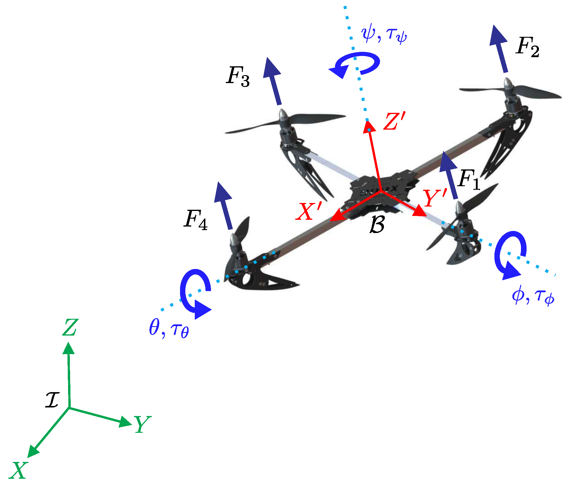
2. Nonlinear Four-Rotor Aerial Vehicle Dynamics

The quadrotor is the most common aerial platform, consisting of four rotors mounted on a cross frame. This underactuated nonlinear system possesses six degrees of freedom and four control inputs only. A quadrotor is usually designed to have a rigid body with a symmetrical mechanical structure, yielding a diagonal and positive definite inertia tensor, where two right-handed coordinated systems are used to describe its pose. Firstly, a global coordinate system I attached to the earth is established with axes X, Y, and Z. Subsequently, the second selected coordinate system is fixed to the quadrotor body, which is identified as B , with axes X’, Y’, and Z’, as shown in Figure 1. The control inputs are achieved by differential control of the thrust generated for each rotor (related to the angular speed): the total thrust or vertical force u and the actuation torques τ ϕ , τ θ , and τ ψ . Translations and rotations on the quadrotor are then provoked by a variation of the angular velocity of each rotor: rotors 1 and 3 spin counter-clockwise, and rotors 2 and 4 in the opposite direction. The pitching moment τ θ is originated by a difference in velocity of rotors 1 and 3. On the other hand, the rolling moment τ ϕ is generated by interaction of the produced forces by rotors 2 and 4. Finally, the yawing moment τ ψ occurs when angular velocities of lateral rotors are increased or decreased.The main control force u stands for the sum of all the vertical forces produced by the rotors.
The produced forces by the rotors and the control inputs are related as follows [49]:
u = i = 1 4 F i τ ψ = i = 1 4 τ M i τ θ = F 3 F 1 l τ ϕ = F 2 F 4 l
where l stands for the longitude from the quadrotor centre of mass to the rotation axes of the rotors, and the induced torque by each electric motor M i is represented by τ M i . Additionally, F i and τ M i depend on the rotors’ blades geometry by means of the thrust and drag coefficients. As observed in Equation (1), by regulating the rotor angular velocities, it is possible to achieve motion in different directions in the space. Thus, by a suitable combination of the control inputs, a quadrotor is able to perform the desired motion reference trajectory tracking as well as stable regulation around a specified position. Reported studies on dynamic modelling and control of the quadrotor [38,49,50,51,52] have been validated through exhaustive numerical simulations and experimental tests, where the Newton–Euler and Euler–Lagrange formalisms are used to describe translational and rotational quadrotor dynamics. It is a common practise to define a vector of generalized coordinates q in order to represent the quadrotor pose:
q = x y z ϕ θ ψ T R 6
where the altitude of the system is described by the set of Euler angles ϕ , θ , and ψ , and the position by the x, y, and z coordinates, both regarding the inertial reference frame I , as depicted in Figure 1.
In the present study, the following nonlinear dynamic model of the quadrotor is considered [8,51,53,54]:
m x ¨ = u sin θ + f x ( t ) m y ¨ = u cos θ sin ϕ + f y ( t ) m z ¨ = u cos θ cos ϕ m g + f z ( t ) J x ϕ ¨ = J y J z θ ˙ ψ ˙ J r Ω n θ ˙ + τ ϕ + τ ϕ d ( t ) J y θ ¨ = J z J x ϕ ˙ ψ ˙ + J r Ω n ϕ ˙ + τ θ + τ θ d ( t ) J z ψ ¨ = J x J y ϕ ˙ θ ˙ + τ ψ + τ ψ d ( t )
where m is the total quadrotor mass, J x , J y and J z are the diagonal elements of the tensor of inertia expressed in the body frame, and g is the acceleration constant of gravity. f i ( t ) , i = x , y , z , and τ j d ( t ) , j = ϕ , θ , ψ , represent exogenous harmonic torques and forces affecting translational and rotational dynamics. In the next section, nonphysical dynamic vibration absorbers are designed and embedded into desired motion tracking control signals to suppress the unwanted vibrating disturbances f i ( t ) and τ j d ( t ) .

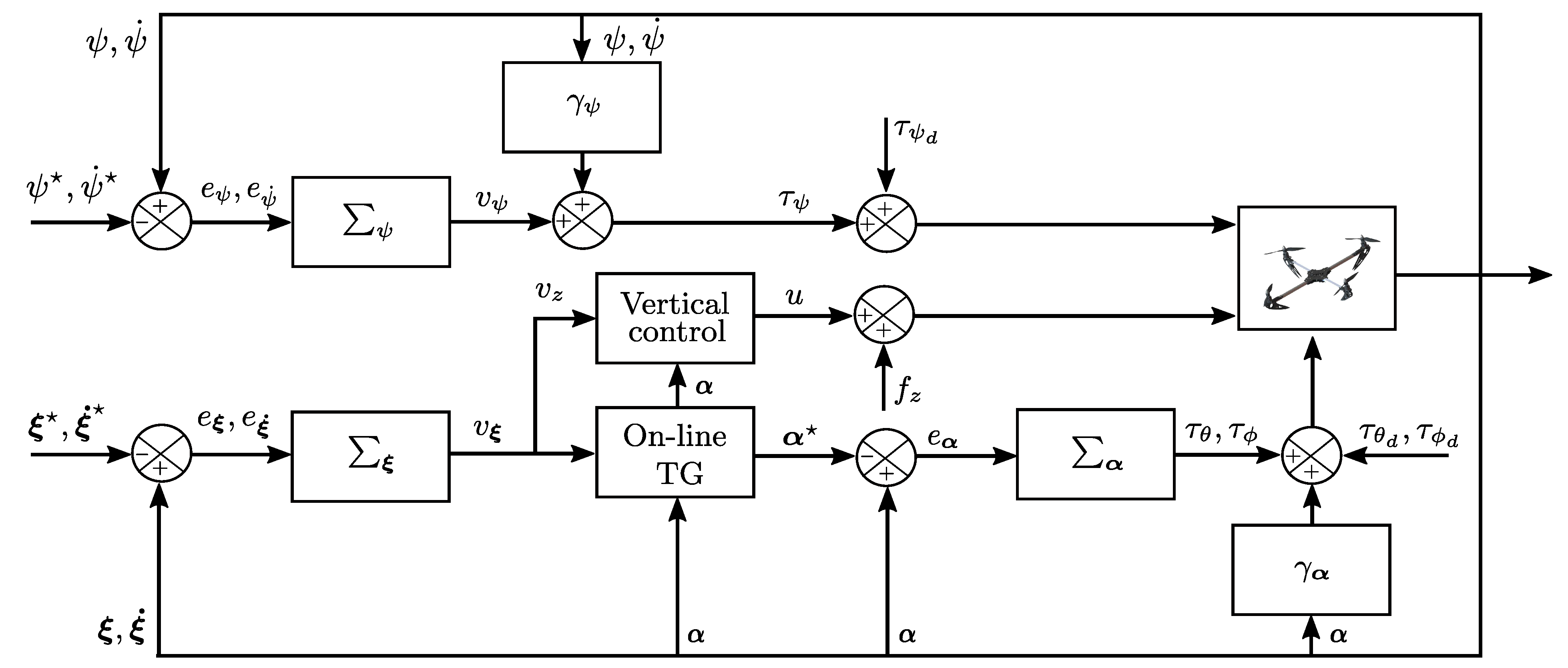
3. An Active Vibration Control Design Approach for Quadrotors

To depict the central ideas of the proposed control scheme to track planned motion profiles with additional vibration suppression capability for four-rotor helicopters, consider the main or primary vibrating system Σ 1 to be protected against harmonic vibrations induced by excitation forces f using an active dynamic vibration absorber Σ 2 as follows
Σ 1 : m y ¨ + c y ˙ + k y = k a ( y a y ) + f ( t ) Σ 2 : m a y ¨ a + c a y ˙ a + k a ( y a y ) = u a
In this representation, y is the position output variable of the main vibrating system, and y a is the position signal of the dynamic vibration absorber. u a represents an exogenous control force which can be implemented to extend the capabilities of the vibration absorber for closed-loop reference trajectory tracking and simultaneous active vibration suppression on the primary system. Positive parameters of mass, stiffness, and viscous damping of the main mechanical system subjected to undesirable vibrations are respectively denoted by m, k, and c > 0 . Physical parameters of mass, stiffness, and damping of the dynamic vibration absorption device Σ 2 are denoted by m a , k a , and c a . Harmonic disturbance forces f ( t ) are described as
f ( t ) = F 0 sin ( Ω t )
where the amplitude and frequency parameters are denoted by F 0 and Ω . The tuning frequency of the dynamic vibration absorber is then set as
ω a = k a m a = Ω
A high forced vibration attenuation level closed to the excitation frequency Ω can then be achieved using a weakly damped absorber, that is, by selecting the viscous damping parameter as c a 0 .
Then, consider the disturbed vibrating mechanical system Σ 1 in the state-space representation
Σ 1 : y ˙ 1 = y 2 y ˙ 2 = k m y 1 c m y 2 + 1 m u + 1 m f y = y 1
Here, the control input u should be designed so that undesirable harmonic disturbances f affecting the output signal y are actively suppressed. In the present study, virtual (nonphysical) dynamic vibration absorbers Σ 2 are proposed to be properly embedded into the dynamic controller as follows:
Σ 2 : η ˙ 1 = η 2 η ˙ 2 = k a m a ( η 1 y 1 ) u = k a ( η 1 y 1 )
In this fashion, harmonic vibration absorption capabilities can be added to dynamic controllers. The design parameters of the virtual dynamic vibration absorber should be selected to satisfy Ω 2 = k a / m a . The closed-loop system dynamics is then governed by
y ˙ 1 = y 2 y ˙ 2 = y 3 y ˙ 3 = y 4 y ˙ 4 = k k a m m a y 1 c k a m m a y 2 k + k a m + k a m a y 3 c m y 4
with y 1 = y , y 2 = y ˙ , y 3 = y ¨ , and y 4 = y ( 3 ) . Notice that the asymptotic stability of the closed-loop system is guaranteed by selecting the design parameters as m a , k a > 0 , which is proven as follows. The time derivative of the Lyapunov function candidate
V y 1 , y 2 , y 3 , y 4 = 1 2 k y 1 2 + 1 2 m y 2 2 + 1 2 k a k k a y 1 + c k a y 2 + m k a y 3 2 + 1 2 m a k + k a k a y 2 + c k a y 3 + m k a y 4 2
along the trajectories of the system dynamics (9) yields
V ˙ y 1 , y 2 , y 3 , y 4 = c y 2 2 0
Therefore, from the LaSalle’s invariance theorem,
lim t y i = 0 , i = 1 , , 4
Then, dynamic controllers based on virtual vibration absorbers (8) for active vibration suppression and desired motion profile tracking on four-rotor helicopters are proposed as follows:
u = 1 cos ϕ cos θ m z ¨ + v z + m g τ ϕ = J x ϕ ¨ + v ϕ J y J z θ ˙ ψ ˙ + J r θ ˙ Ω n τ θ = J y θ ¨ + v θ J z J x ϕ ˙ ψ ˙ J r ϕ ˙ Ω n τ ψ = J z ψ ¨ + v ψ J x J y ϕ ˙ θ ˙
with
Σ i : η ˙ 1 , i = η 2 , i η ˙ 2 , i = k a , i m a , i ( η 1 , i e i ) v i = β 0 , i e i β 1 , i e ˙ i + k a , i ( η 1 , i e i )
where e i = i i , i = x , y , z , ψ , θ , ϕ , stands for tracking errors; x , y , z , and ψ are reference profiles planned offline; and θ and ϕ are trajectories computed online by
tan θ = m x ¨ + v x m z ¨ + v z + m g cos ϕ
tan ϕ = m y ¨ + v y m z ¨ + v z + m g
Hence, closed-loop dynamics of the trajectory tracking errors is governed by
e x ( 4 ) + β 1 , x m e x ( 3 ) + β 0 , x + k a , x m + k a , x m a , x e ¨ x + β 1 , x k a , x m m a , x e ˙ x + β 0 , x k a , x m m a , x e x = 0 e y ( 4 ) + β 1 , y m e y ( 3 ) + β 0 , y + k a , y m + k a , y m a , y e ¨ y + β 1 , y k a , y m m a , y e ˙ y + β 0 , y k a , y m m a , y e y = 0 e z ( 4 ) + β 1 , z m e z ( 3 ) + β 0 , z + k a , z m + k a , z m a , z e ¨ z + β 1 , z k a , z m m a , z e ˙ z + β 0 , z k a , z m m a , z e z = 0 e ϕ ( 4 ) + β 1 , ϕ J x e ϕ ( 3 ) + β 0 , ϕ + k a , ϕ J x + k a , ϕ m a , ϕ e ¨ ϕ + β 1 , ϕ k a , ϕ J x m a , ϕ e ˙ ϕ + β 0 , ϕ k a , ϕ J x m a , ϕ e ϕ = 0 e θ ( 4 ) + β 1 , θ J y e θ ( 3 ) + β 0 , θ + k a , θ J y + k a , θ m a , θ e ¨ θ + β 1 , θ k a , θ J y m a , θ e ˙ θ + β 0 , θ k a , θ J y m a , θ e θ = 0 e ψ ( 4 ) + β 1 , ψ J z e ψ ( 3 ) + β 0 , ψ + k a , ψ J z + k a , ψ m a , ψ e ¨ ψ + β 1 , ψ k a , ψ J z m a , ψ e ˙ ψ + β 0 , ψ k a , ψ J z m a , ψ e ψ = 0
Therefore, asymptotic tracking of reference trajectories specified for the operation of the aerial vehicle can be achieved by the proper selection of the control design parameters, β 0 , i , β 1 , i > 0 , i = x , y , x , ϕ , θ , ψ , so that the characteristic polynomials associated with Equation (17) are Hurwitz polynomials. Then,
lim t e i ( t ) = 0 lim t i ( t ) = i ( t )
Here, θ and ϕ are used to regulate the x and y position variables toward the desired motion reference trajectories in the horizontal plane. In this fashion, the underactuation condition is then solved. Then, control gains of angular motion should be suitably chosen to be much faster than x and y translation motion. Notice that in order to avoid (uncontrollable) singular configurations of the quadrotor model (3), θ and ϕ angles should be constrained to take values in the open interval ( π / 2 , π / 2 ) .
Figure 2 summarizes the proposed control scheme. Here, the α = θ ϕ and α = θ ϕ vectors, containing both real and references values for roll and pitch angles, are used for purposes of simplicity in the representation. Moreover, vectors ξ = x y z and ξ = x y z stand for the real and planned reference positions. Notice that e ξ represents an error vector containing the x , y and z position errors; then, similar conditions hold for v ξ , e α , Σ ξ , and Σ α . Additionally, the Online TG block represents the trajectory generator mechanism implemented by solving the set equations introduced in (15) and (16). On the other hand, it can be seen that the proposed PD-like motion controllers require velocity and position errors. However, virtual vibration absorbers only need measurements of the quadrotor primary system displacements in order to attenuate the forced vibrations acting on it.

4. Numerical Simulation Results

Several computer simulation results are additionally presented in this section to show the efficient performance of the proposed dynamic control scheme when the quadrotor is tasked to reach desired position trajectories ( x , y , z ) . The external forced vibration suppression capability of the control technique based on virtual vibration absorbers is also confirmed. The numerical method of Runge–Kutta Fehlberg 4/5 was selected for computer simulations, where a fixed time step of 1 ms is adopted. Two scenarios for the operation of the aerial vehicle are described to portray the effectiveness of the introduced desired motion trajectory tracking control approach.

4.1. Scenario 1: Hover Stabilization

In the first case, the quadrotor performs motion regulation around a fixed or stable position (hovering). Thus, let us introduce the position reference profile in (19) that is implemented to obtain smooth transitions between initial and final x, y, and z positions:
Γ = Γ 0 0 t < T 1 Γ 0 + Γ f Γ 0 B z ( t , T 1 , T 2 ) T 1 t T 2 Γ f t > T 2
where Γ 0 and Γ f stand for desired initial and final values of motion trajectories planned for the aerial vehicle, which is characterized by the set of parameters given in Table 1. Meanwhile, B z is a Bézier polynomial [55] defined as
B z ( t , T 1 , T 2 ) = k = 0 n h k t T 1 T 2 T 1 k
with n = 6 , and h 1 = 252 , h 2 = 1050 , h 3 = 1800 , h 4 = 1575 , h 5 = 700 , h 6 = 126 .
Thereafter, the first stage considers moving the quadrotor from an initial vertical position z 0 = 0 m to a desired height of z f = 10 m within a time window of 6 s, starting after 1 s. Subsequently, the rotorcraft is displaced to desired positions in the horizontal plane, from initial conditions x 0 = 0 m and y 0 = 0 m to a final position defined by x f = 5 m and y f = 6 m in 10 and 15 s, respectively. On the other hand, the yaw angle is also simultaneously taken from ψ 0 = 0.5 rad to ψ f = 0 rad by using the Bézier curve until time reaches the proximity of 19 s. Then, a time-varying trajectory is adopted as the planned reference, where
ψ = 0.5 cos ( 0.25 t ) m ψ ˙ = 0.1250 sin ( 0.25 t ) m / s ψ ¨ = 0.03125 cos ( 0.25 t ) m / s 2
The closed-loop system performance with the controller (13) and (14) in the absence of harmonic forces is shown in Figure 3. From the figures, the sufficiently smooth transference towards the motion configuration planned for the quadrotor thanks to the use of Bézier interpolation polynomials between specified operating states is evident [56].
As described in the control design section, the planned references for solving the quadrotor underactuation condition are computed online and included in the control loop scheme, where the planned positions and velocity references are properly used as a feedforward action. In fact, the underactuation issue is solved by ensuring a faster response for the rotational rather than the translational dynamics. Moreover, note in Figure 4 a proper tracking of the angular references yielded by the trajectory generator (Figure 2) along with their respective time derivatives. Additionally, acceptable levels of energy from the control inputs are achieved, as corroborated in Figure 5.
In several indoor and outdoor real applications, such as filming and power line inspection, an effective stabilization of the quadrotor around a desired position while wind is inducing forced vibrations is demanded. Therefore, and in spite of the good performance achieved with our proposal, it is evident that we need to analyse the system behaviour when subjected to induced wind forced vibrations, trying to emulate real quadrotor flight conditions that deteriorate the system performance. Disturbance forces are intentionally injected in this simulation scenario as follows: f x = sin ( 5 t ) N, f y = sin ( 5 t ) N, and f z = sin ( 20 t ) N for t > 20 s. Moreover, disturbance torques are also included as τ ϕ d = 0.3 sin ( 100 t ) Nm for t > 5 s, τ θ d = 0.3 sin ( 80 t ) Nm for t > 20 s, and τ ψ d = sin ( 30 t ) Nm for t > 16 s. Consequently, the virtual dynamic vibration absorbers are tuned at ω a , z = 20 rad/s, ω a , x = ω a , y = 5 rad/s with m a , j = m / 2 . Similarly, in Figure 6 and Figure 7, the acceptable regulation around x = 5 m, y = 6 m, and z = 10 m in the presence of sustained harmonic disturbances can be observed.
On the other hand, Figure 6b confirms the satisfactory position control performance by adjusting the magnitude of the main control force input for situations where the quadrotor is being disturbed. Moreover, effective harmonic force suppression by means of the controlled trajectories of pitch and roll angles can be also corroborated in Figure 7. It is also relevant to highlight the soft and acceptable levels of the computed control inputs, so that the control torques and force used for both regulation tasks and active rejection of undesirable frequency harmonic vibrations are then suitable for implementation in a physical model. We then conclude that our proposal is quite promising, in the sense that acceptable attenuation levels of forced vibration are achieved while hover stabilization tasks are performed.

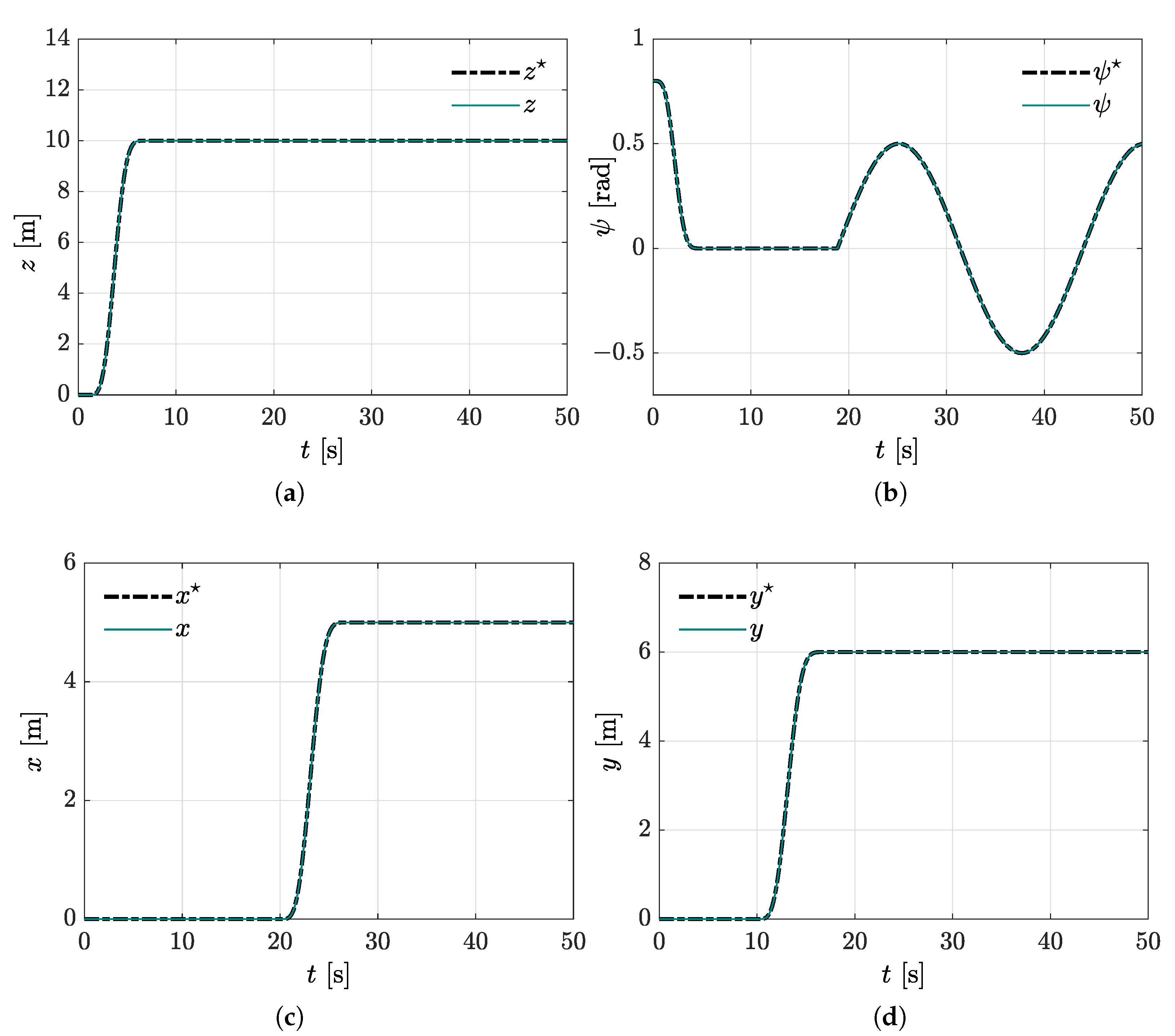
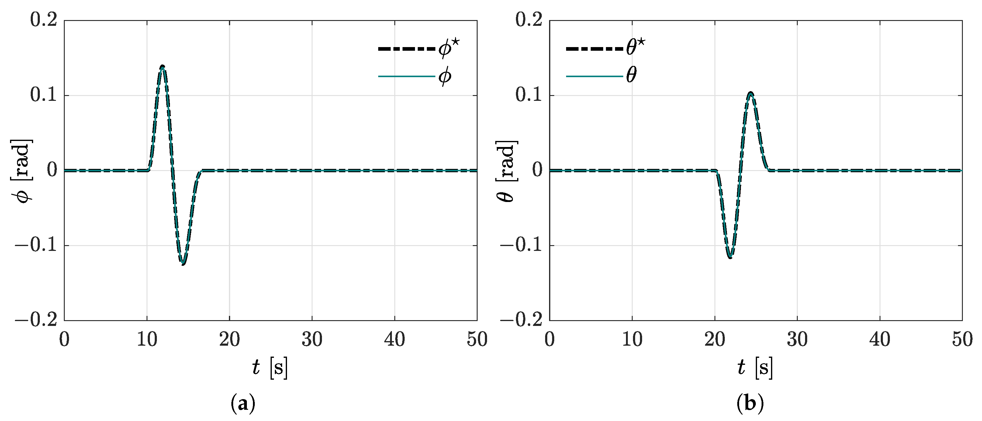
4.2. Scenario 2: Trajectory Tracking

In some quadrotor applications, such as surveillance and monitoring, payload delivering, mapping and inspection, etc., it is required to following either prescribed or online computed trajectories. Usually, while doing these tasks, the quadrotor is subjected to wind disturbances that produce undesired forced vibrations on the vehicle. Therefore, for the second operating scenario, the quadrotor should track a planned reference in four different cases: in the absence of disturbances and using the full control scheme; in the presence of disturbance force and torque inputs without using the vibration absorber compensation; in the presence of disturbance force and torque inputs but using the full control scheme; and finally, as in the previous case but considering noisy sensor measurements.

4.2.1. Unperturbed Trajectory Tracking

For such purposes, a Lissajous curve is chosen as the planned reference for the motion on the horizontal plane. Meanwhile, the Bézier interpolation setup remains the same as the first scenario for controlling the z position. In the same way, the planned reference for yawing motion is described by an interpolation curve with ψ 0 = 0 rad and ψ f = 0.72 rad, and transition times defined by T 1 = 1 s and T 2 = 7 s. In Table 2, the x and y trajectory references for position, velocity, and acceleration for scenario 2 are summarized. The equations allow us to see that the demanded motions for a proper trajectory tracking are a control challenge, since disturbances reasonably affect the quadrotor performance.
During the experiments, the parameter values are the following: k = 1 / 3 , A = 10 , and d T = t / 2 . It is also important to mention that control gains for both experiments were selected as follows:
β 0 , i = ω n , i 2 β 1 , i = 2 ζ i ω n , i
with ω n , z = 10 rad/s; ω n , j = 5 rad/s, j = x , y ; ω n , θ = 50 rad/s; ω n , ϕ = 30 rad/s; ω n , ψ = 40 rad/s; ζ i = 0.1 , i = x , y , θ , ϕ ; and ζ j = 0.5 , j = z , ψ .
The controlled trajectories of pitch and roll angles used to achieve the motion in x and y directions are depicted in Figure 8, as well as the control input torques applied to the helicopter. As expected, since disturbance are not included in this case, a proper functioning of the introduced scheme for tracking tasks is corroborated, as shown in Figure 9 and Figure 10.

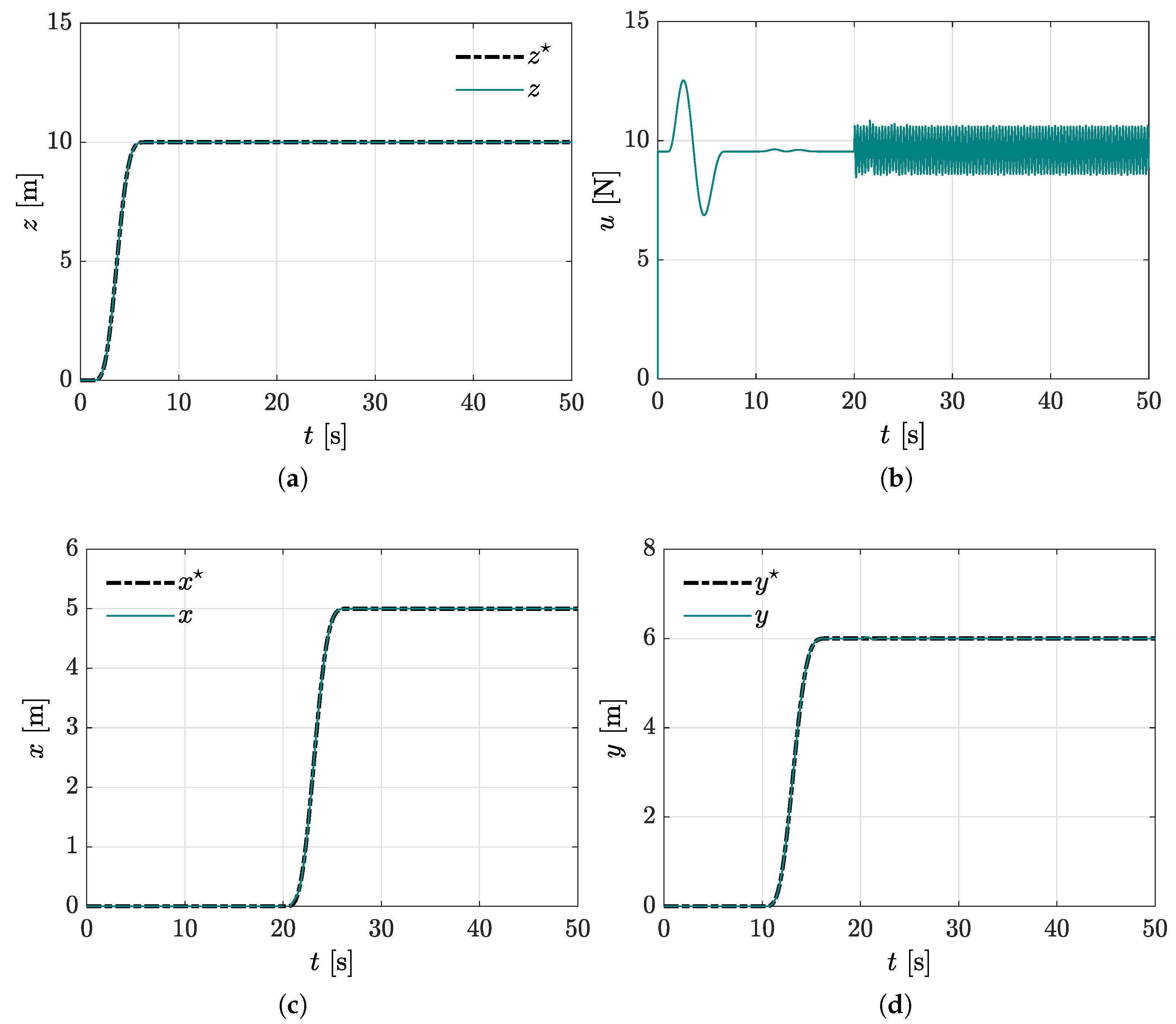
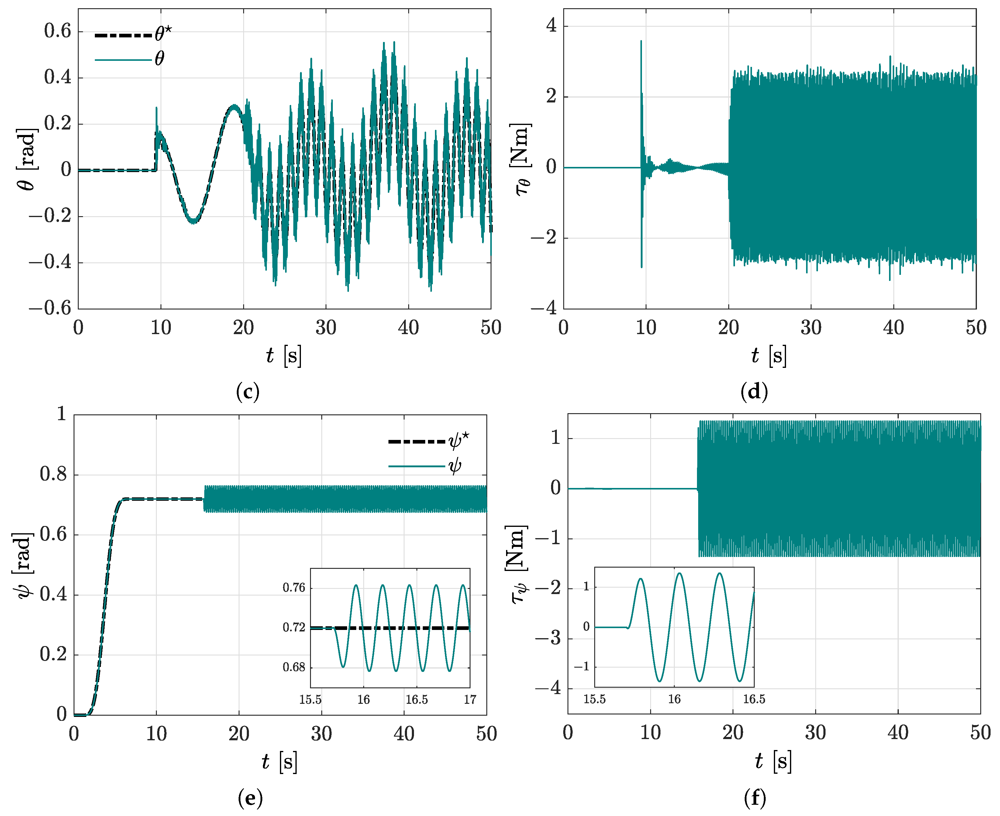
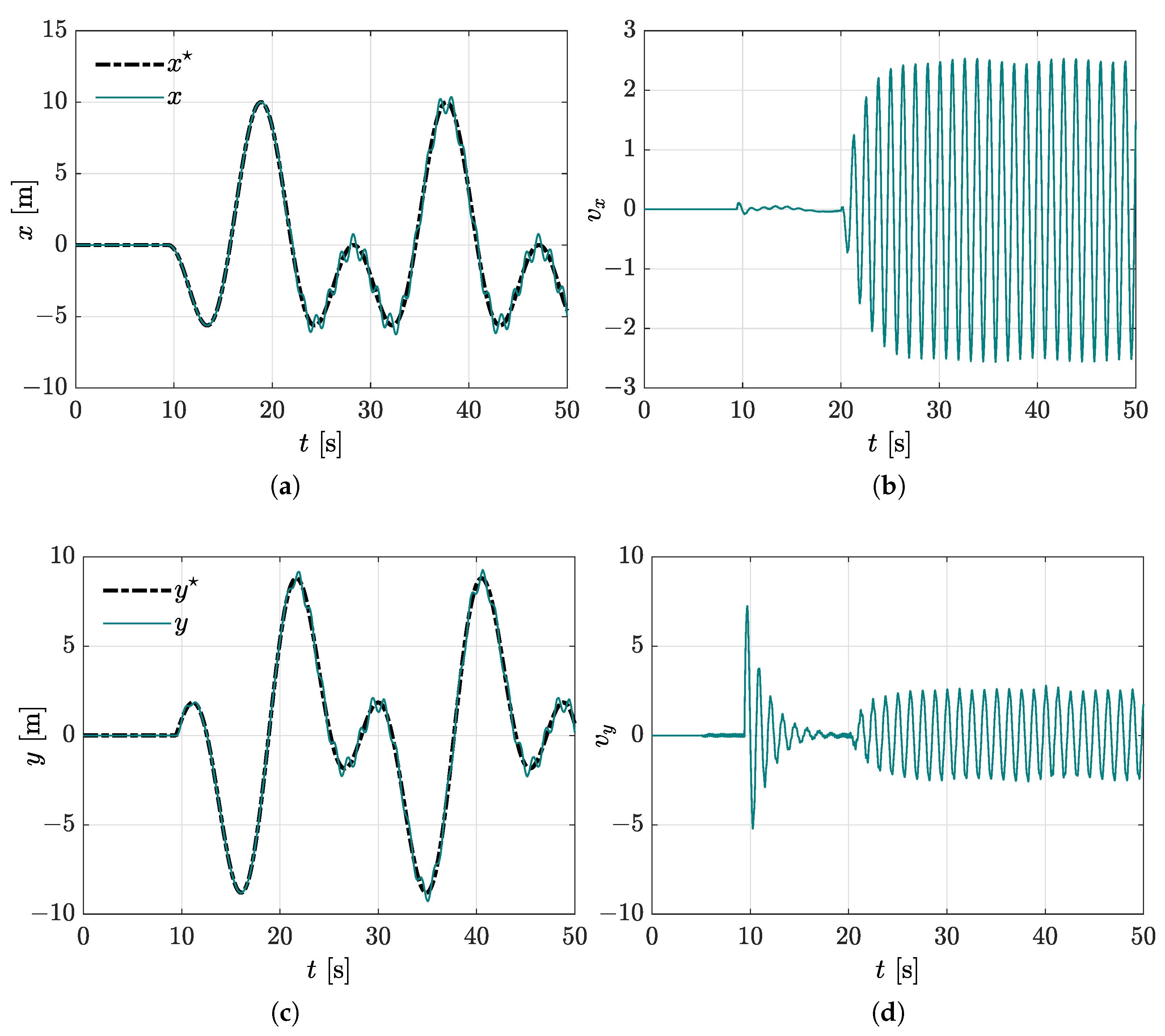
4.2.2. Perturbed Trajectory Tracking without the Virtual Absorber Compensation

In the present case, we intentionally disconnect the vibration absorber compensation in order to visualise the closed-loop dynamic response in the presence of external disturbances. It is important to mention that wind disturbances are manifested mainly through crosswinds, wind shear, or gusts, which produce forced vibrations in the vehicles. Additionally, note that this study is focused on preliminary results where a class of disturbances is considered; however, the analysis will be extended for other types of disturbances in future works.
Disturbance forces are intentionally injected in this simulation scenario as follows: f x = 0.5 sin ( 5 t ) N, f y = 0.5 sin ( 5 t ) N, and f z = sin ( 10 t ) N for t > 20 s. Moreover, disturbance torques are also included: τ ϕ d = 0.3 sin ( 30 t ) Nm for t > 5 s, τ θ d = 0.5 sin ( 50 t ) Nm for t > 20 s, and τ ψ d = sin ( 40 t ) Nm for t > 16 s. Observe from Figure 11 the presence of undesired oscillations induced by the vibrating torques and forces. Additionally, from Figure 12, the disturbance negative effects on vertical motions is also corroborated. Moreover, a significant deviation from the planned references is also seen in Figure 13. Thus, vibration attenuation capabilities of the virtual vibration absorbers are evidenced from this scenario.

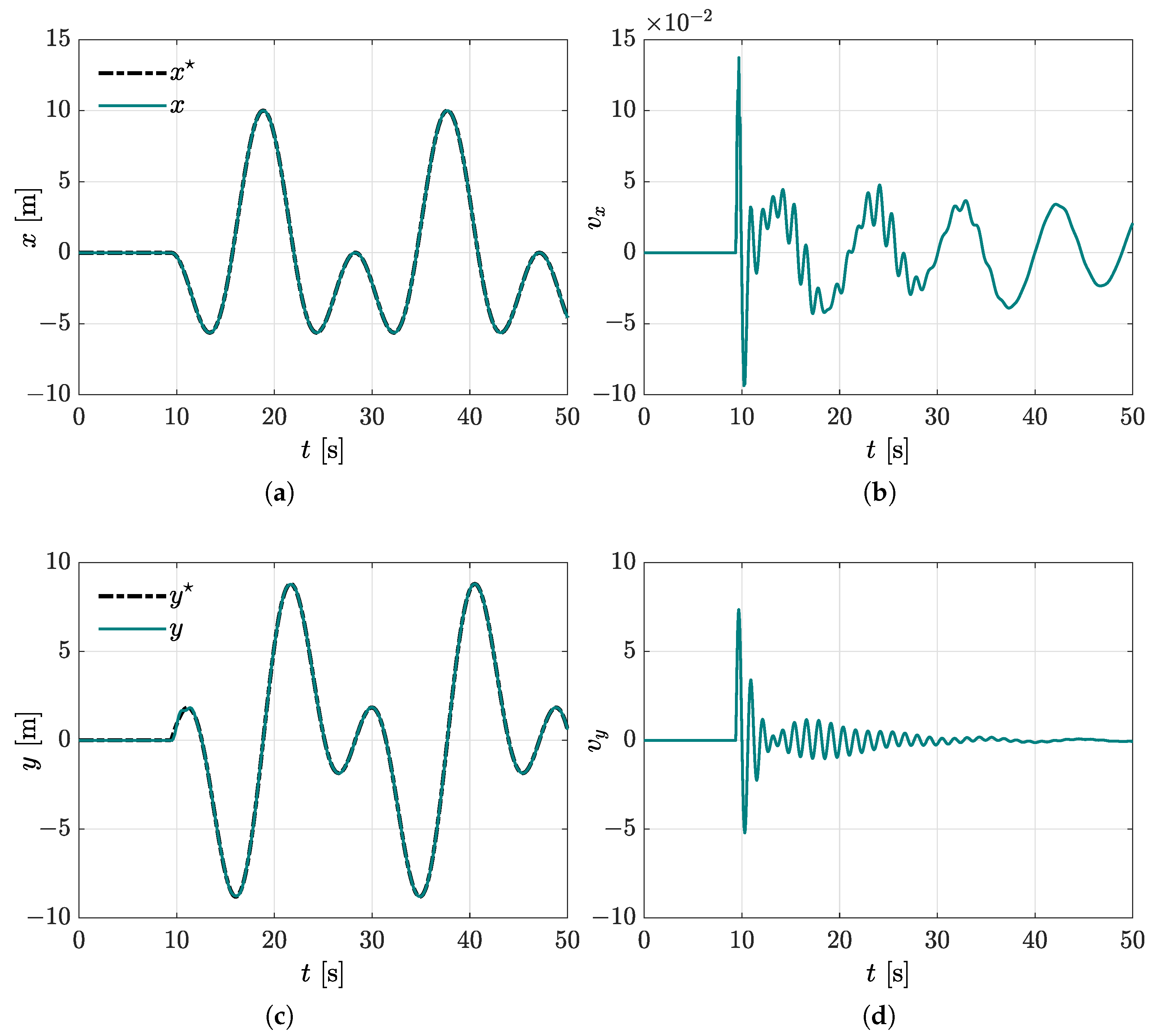
4.2.3. Perturbed Trajectory Tracking with the Virtual Absorber Compensation

In this case study, the performance of the quadrotor by using the proposed virtual vibration absorber-based motion control is examined. In Figure 14, the robustness of the introduced approach for the compensation of rotational motion affected by disturbance torque input is also corroborated. The benefits for using the virtual vibration absorber are evident, since vibrations are significantly attenuated, as corroborated in Figure 15. Moreover, note from Figure 16 that the planned motion is achieved on the horizontal plane, where controller positions x and y track the parametric references of the Lissajous curve by using the proposed controllers. The compensation actions in the control signals are also seen. Thus, considering the equations in Table 2, a proper path following of the plane is ensured, as observed in Figure 17.
Finally, in Figure 18 the 3D motion of the quadrotor vehicle is presented, which describes a suitable 3D path following as stated by the planned reference. It is important to highlight that in spite of being subjected to disturbance force and torques, the quadrotor is able to accomplish the planned task by using the proposed control scheme. Thus, we conclude from the simulation results that virtual vibration absorbers are successfully included in the synthesis of motion control of a quadrotor vehicle, where the controller gives satisfactory results for a wide range of operation conditions in regulation and tracking tasks.

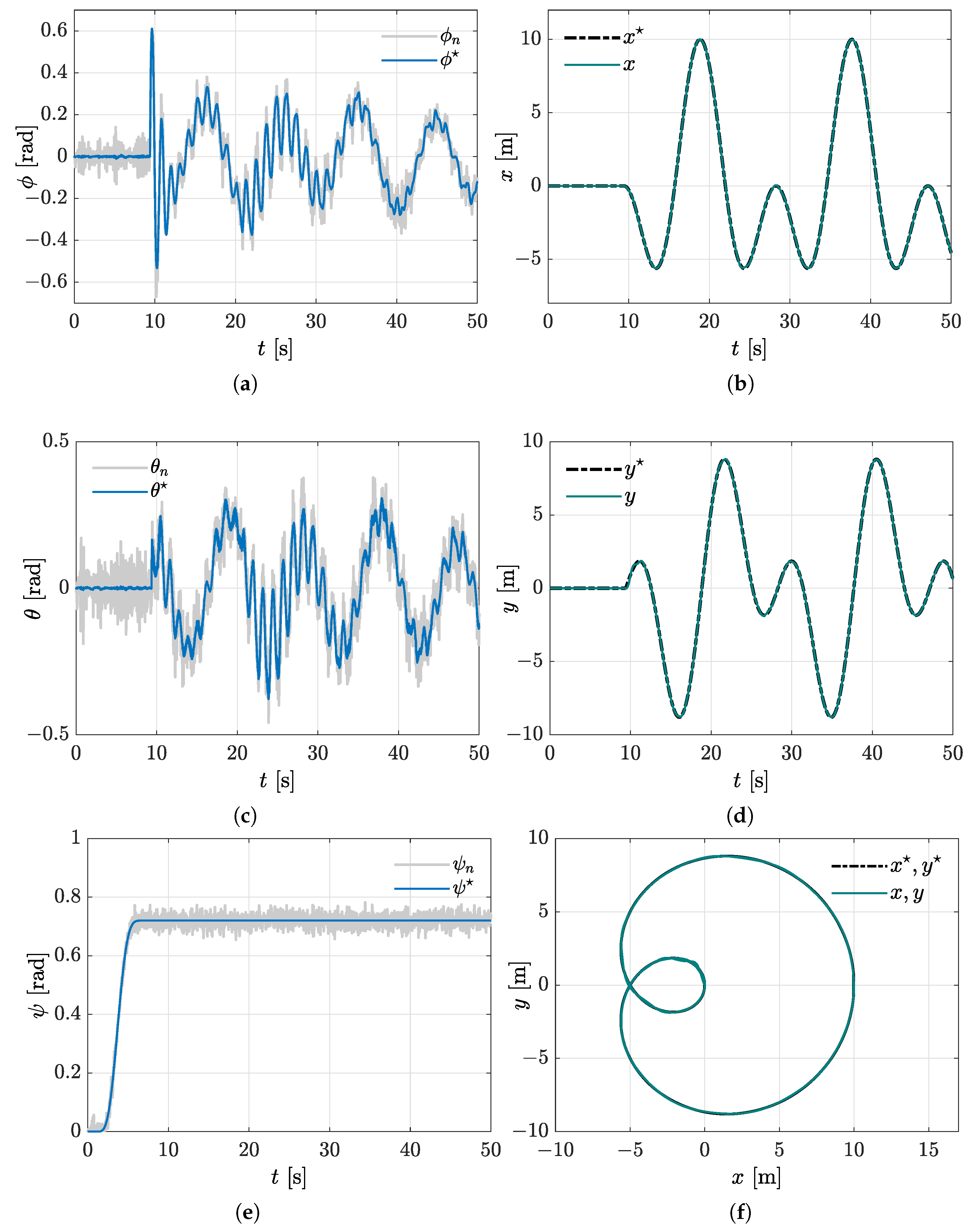
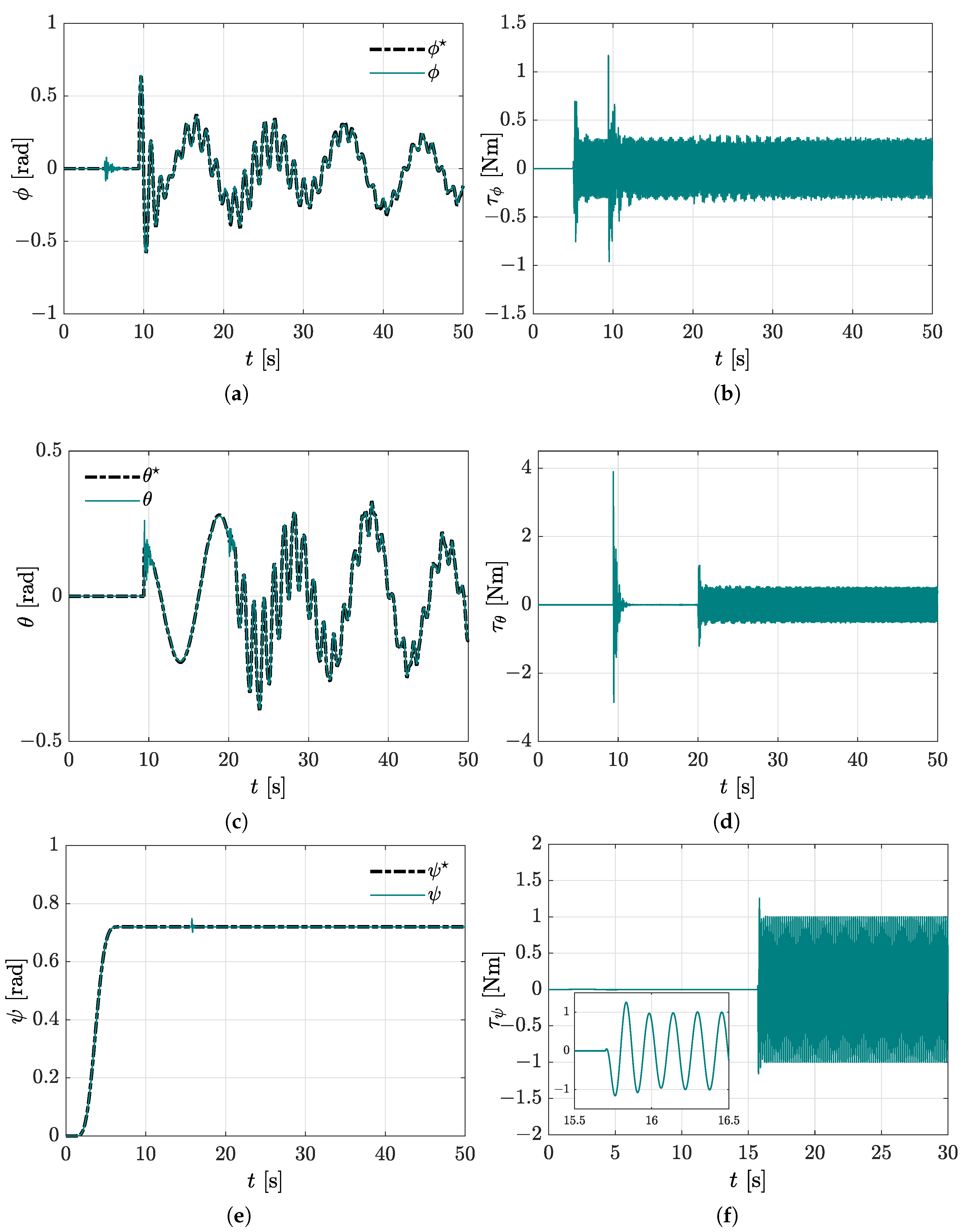
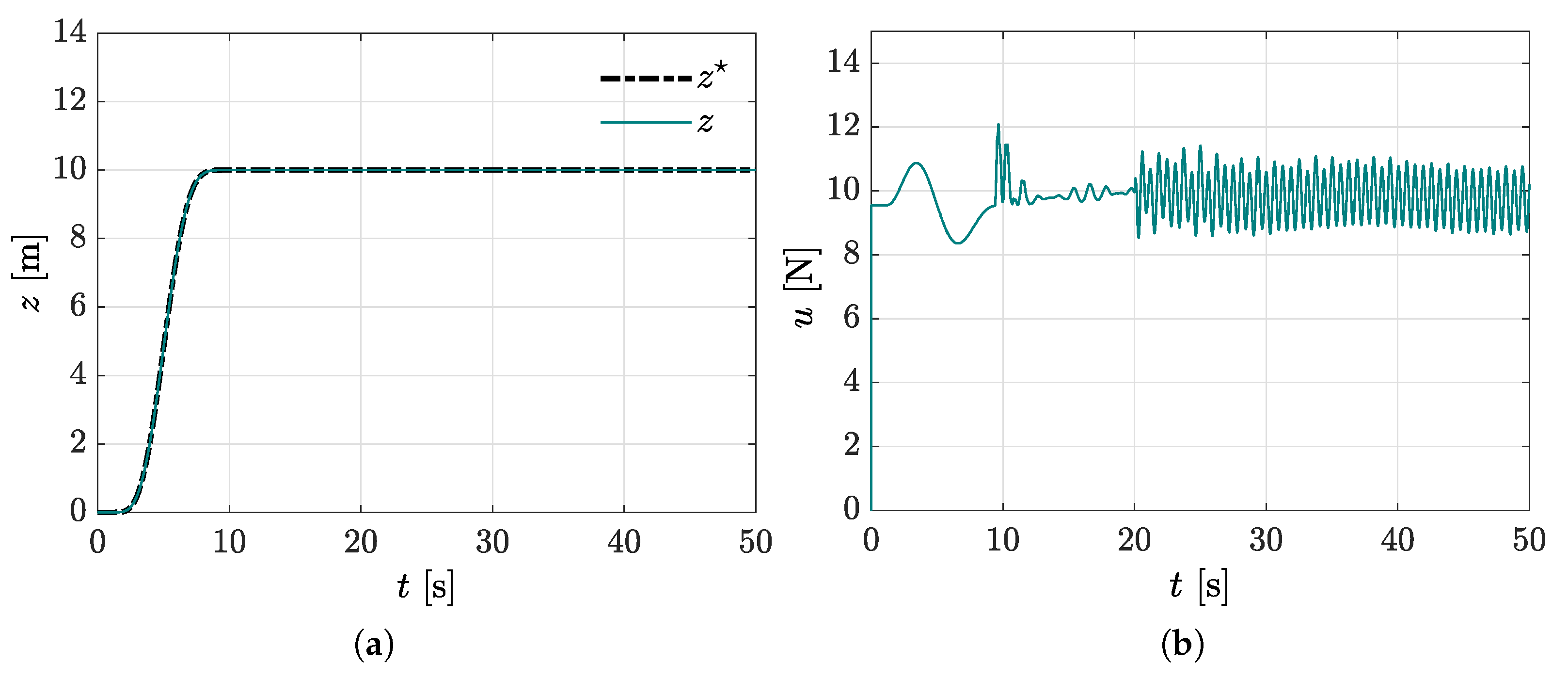
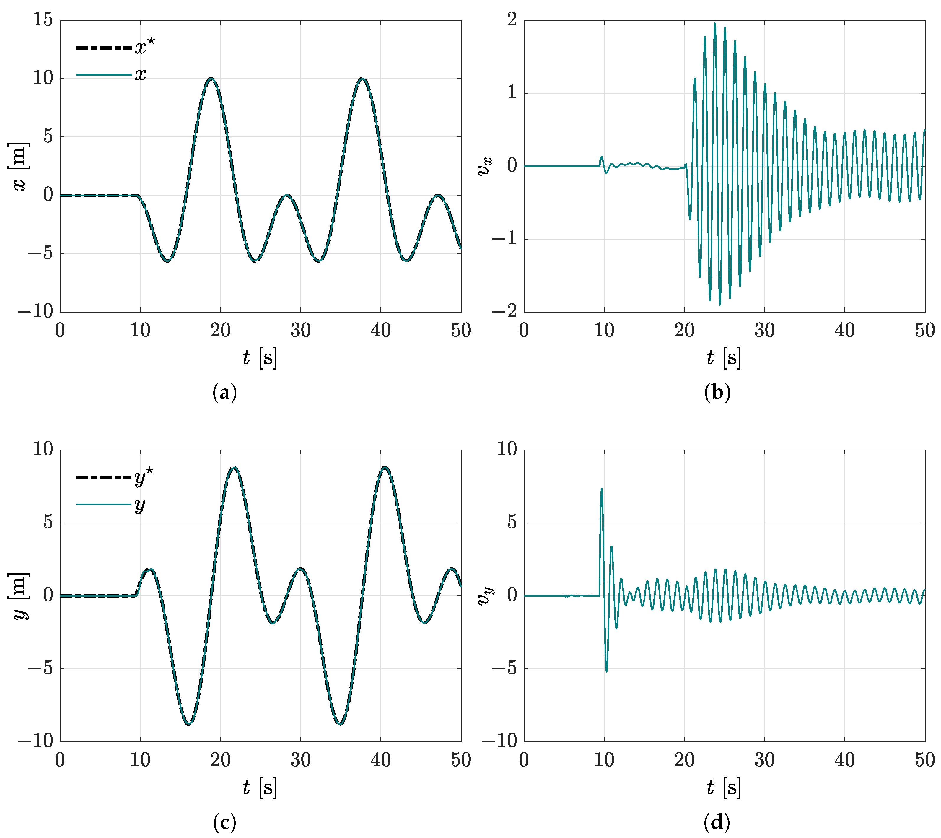
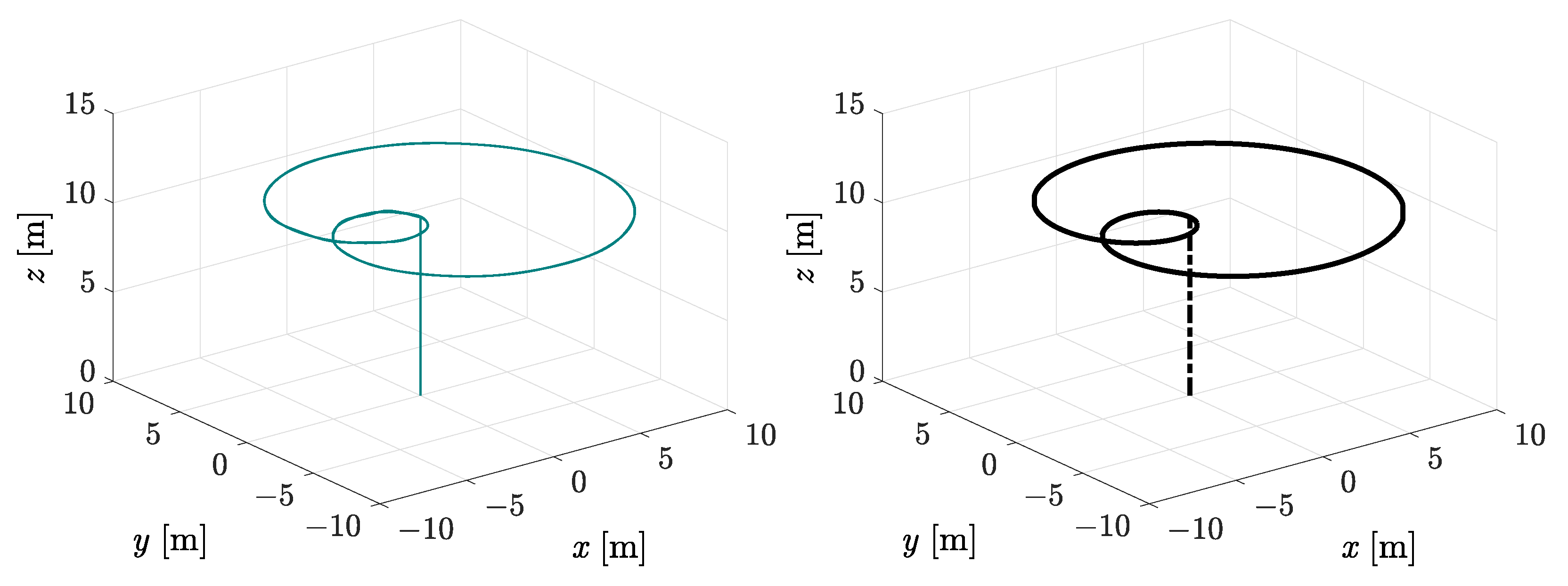
4.2.4. Perturbed Trajectory Tracking with the Virtual Absorber Compensation and Noisy Sensor Measurements

The last case study in the second operating scenario is carried out while both external disturbances and reasonable additive noises corrupting the roll-pitch-yaw angle measurements are considered. Here, noisy measurements of the angular variables are simulated regarding white noise with uniform distribution U ( 0 , 1 ) in the interval [ 0 , 1 ] and an unpredictable component of high frequency with a normal distribution N ( μ , σ ) , mean value μ = 0 , and standard deviation σ = 1 , which is described as follows:
γ n = γ + Γ U ( 0 , 1 ) + sign ( N ( μ , σ ) ) 0.5
for γ = ϕ , θ , ψ and Γ = 0.25 . An acceptable reference trajectory tracking under undesirable vibrating disturbances and reasonable noise levels can be evidenced in Figure 19. Notice that high-frequency oscillations are generated along with the online computed references ϕ and θ due to the dependence on virtual controllers v x and v y as observed in Figure 19a,c. Nevertheless, for highly noisy operational conditions for unmanned aerial vehicles subjected to significant vibrating disturbances, the measurement sensor signals should be pre-filtered and suitably conditioned to reduce harmful noise levels.

5. Conclusions

In this paper, a new active vibration control approach based on virtual dynamic vibration absorbers for desired motion reference trajectory tracking and active suppression of undesirable harmonic vibration disturbances for a four-rotor aerial vehicle was proposed. Nonphysical dynamic vibration absorbers were tuned at specified excitation frequencies and then embedded into motion trajectory tracking controllers designed for the MIMO underactuated nonlinear aerial dynamic system. In contrast to other important contributions on efficient and robust trajectory tracking control for quadrotors, our control design perspective considers the synthesis of virtual dynamic vibration absorbers to add active vibration suppression capabilities to motion tracking controllers for four-rotor helicopters. Completely different from research works related to the design of real dynamic vibration absorbers for undesirable vibration attenuation on many realistic mechanical systems, in the present study, the mathematical structure of physical vibration absorbers is exploited for synthesis of dynamic controllers for aerial vehicles. Two operating scenarios were presented to highlight the feasibility of the proposed dynamic control scheme to perform regulation and trajectory tracking tasks. Numerical simulation results showed an acceptable active vibration control performance by regulating the motion of the quadrotor towards the established reference trajectories in the presence of forced harmonic vibrations. Thus, a satisfactory tracking of the motion reference trajectories generated online and offline specified for the multivariable nonlinear system was numerically confirmed. Hence, analytical and numerical results reveal that the mathematical structure of dynamic vibration absorbers can be exploited to design planned motion tracking control schemes with forced harmonic vibration compensation capabilities for unmanned four-rotor aerial vehicles. Furthermore, the presented vibration absorption approach can be properly combined with diverse robust linear and nonlinear control design methodologies for the synthesis of robust control policies for four-rotor aerial vehicles. Future research studies will deal with the extension of the presented results for different configurations of aerial vehicles subjected to multiple excitation frequency forced vibrations using virtual dynamic vibration absorbers. In this context, the incorporation of active disturbance rejection capabilities to compensate a wide spectrum of periodic and aperiodic vibrations, as well as parametric uncertainty and unmodelled nonlinear dynamics, will be also considered in subsequent studies.

Author Contributions

Conceptualization, F.B.-C. and H.Y.-B.; Methodology, F.B.-C., H.Y.-B. and R.T.-O.; Software, H.Y.-B.; Validation, F.B.-C., H.Y.-B. and R.T.-O.; Formal analysis, F.B.-C., H.Y.-B., R.T.-O., A.V.-G., A.F.-C. and I.L.-G.; Investigation, F.B.-C., H.Y.-B., R.T.-O., A.V.-G., A.F.-C. and I.L.-G.; Writing—original draft, F.B.-C. and H.Y.-B.; Supervision, F.B.-C., H.Y.-B., R.T.-O. and A.V.-G.; Project administration, A.V.-G. All authors have read and agreed to the published version of the manuscript.

Funding

This research received no external funding.

Institutional Review Board Statement

Not applicable.

Informed Consent Statement

Not applicable.

Data Availability Statement

Not applicable.

Conflicts of Interest

The authors declare no conflict of interest.

References

  1. Rao, S. Mechanical Vibrations, 6th ed.; Pearson: London, UK, 2018. [Google Scholar]
  2. Korenev, B.G.; Reznikov, L.M. Dynamic Vibration Absorbers: Theory and Technical Applications, 1st ed.; John Wiley & Sons: Hoboken, NJ, USA, 1993. [Google Scholar]
  3. Braun, S.; Ewins, D.; Rao, S. Encyclopedia of Vibration, 1st ed.; Academic Press: London, UK, 2002. [Google Scholar]
  4. Piersol, A.; Paez, T. Harris’s Shock and Vibration; McGraw-Hill: New York, NY, USA, 2010. [Google Scholar]
  5. Krysinski, T.; Malburet, F. Mechanical Vibrations: Active and Passive Control; ISTE Ltd.: London, UK, 2007. [Google Scholar]
  6. Beltran-Carbajal, F.; Silva-Navarro, G. Output feedback dynamic control for trajectory tracking and vibration suppression. Appl. Math. Model. 2020, 79, 793–808. [Google Scholar] [CrossRef]
  7. Beltran-Carbajal, F.; Silva-Navarro, G. Adaptive-Like Vibration Control in Mechanical Systems with Unknown Paramenters and Signals. Asian J. Control 2013, 15, 1613–1626. [Google Scholar] [CrossRef]
  8. Mahony, R.; Kumar, V.; Corke, P. Multirotor Aerial Vehicles: Modeling, Estimation, and Control of Quadrotor. IEEE Robot. Autom. Mag. 2012, 19, 20–32. [Google Scholar] [CrossRef]
  9. Kim, J.; Kim, S.; Ju, C.; Son, H.I. Unmanned Aerial Vehicles in Agriculture: A Review of Perspective of Platform, Control, and Applications. IEEE Access 2019, 7, 105100–105115. [Google Scholar] [CrossRef]
  10. Borkar, A.V.; Hangal, S.; Arya, H.; Sinha, A.; Vachhani, L. Reconfigurable formations of quadrotors on Lissajous curves for surveillance applications. Eur. J. Control 2020, 56, 274–288. [Google Scholar] [CrossRef]
  11. Rodríguez-Mata, A.E.; Flores, G.; Martínez-Vásquez, A.H.; Mora-Felix, Z.D.; Castro-Linares, R.; Amabilis-Sosa, L.E. Discontinuous High-Gain Observer in a Robust Control UAV Quadrotor: Real-Time Application for Watershed Monitoring. Math. Probl. Eng. 2018, 2018, 4940360. [Google Scholar] [CrossRef]
  12. Bhola, R.; Krishna, N.H.; Ramesh, K.; Senthilnath, J.; Anand, G. Detection of the power lines in UAV remote sensed images using spectral-spatial methods. J. Environ. Manag. 2018, 206, 1233–1242. [Google Scholar] [CrossRef]
  13. Song, B.D.; Park, K.; Kim, J. Persistent UAV delivery logistics: MILP formulation and efficient heuristic. Comput. Ind. Eng. 2018, 120, 418–428. [Google Scholar] [CrossRef]
  14. Nex, F.; Remondino, F. UAV for 3D mapping applications: A review. Appl. Geomat. 2014, 6, 1–15. [Google Scholar] [CrossRef]
  15. Silvagni, M.; Tonoli, A.; Zenerino, E.; Chiaberge, M. Multipurpose UAV for search and rescue operations in mountain avalanche events. Geomat. Nat. Hazards Risk 2017, 8, 18–33. [Google Scholar] [CrossRef] [Green Version]
  16. Shakhatreh, H.; Sawalmeh, A.H.; Al-Fuqaha, A.; Dou, Z.; Almaita, E.; Khalil, I.; Othman, N.S.; Khreishah, A.; Guizani, M. Unmanned Aerial Vehicles (UAVs): A Survey on Civil Applications and Key Research Challenges. IEEE Access 2019, 7, 48572–48634. [Google Scholar] [CrossRef]
  17. Bruno Siciliano, O.K.E. Springer Handbook of Robotics, 2nd ed.; Springer International Publishing: Berlin/Heidelberg, Germany, 2016. [Google Scholar]
  18. Yu, G.; Cabecinhas, D.; Cunha, R.; Silvestre, C. Quadrotor trajectory generation and tracking for aggressive maneuvers with attitude constraints. IFAC-PapersOnLine 2019, 52, 55–60. [Google Scholar] [CrossRef]
  19. Falanga, D.; Kim, S.; Scaramuzza, D. How Fast Is Too Fast? The Role of Perception Latency in High-Speed Sense and Avoid. IEEE Robot. Autom. Lett. 2019, 4, 1884–1891. [Google Scholar] [CrossRef]
  20. Hönig, W.; Preiss, J.A.; Kumar, T.K.S.; Sukhatme, G.S.; Ayanian, N. Trajectory Planning for Quadrotor Swarms. IEEE Trans. Robot. 2018, 34, 856–869. [Google Scholar] [CrossRef]
  21. Satici, A.C.; Poonawala, H.; Spong, M.W. Robust Optimal Control of Quadrotor UAVs. IEEE Access 2013, 1, 79–93. [Google Scholar] [CrossRef]
  22. Bouabdallah, S.; Noth, A.; Siegwart, R. PID vs. LQ Control Techniques Applied to an Indoor Micro Quadrotor. In Proceedings of the 2004 IEEE/RSJ International Conference on Intelligent Robots and Systems (IROS), Sendai, Japan, 28 September–2 October 2004; Volume 3, pp. 2451–2456. [Google Scholar]
  23. Foehn, P.; Scaramuzza, D. Onboard State Dependent LQR for Agile Quadrotors. In Proceedings of the 2018 IEEE International Conference on Robotics and Automation (ICRA), Brisbane, QLD, Australia, 21–25 May 2018; pp. 6566–6572. [Google Scholar]
  24. Dierks, T.; Jagannathan, S. Output Feedback Control of a Quadrotor UAV Using Neural Networks. IEEE Trans. Neural Netw. 2010, 21, 50–66. [Google Scholar] [CrossRef] [PubMed]
  25. Yañez-Badillo, H.; Beltran-Carbajal, F.; Tapia-Olvera, R.; Favela-Contreras, A.; Sotelo, C.; Sotelo, D. Adaptive Robust Motion Control of Quadrotor Systems Using Artificial Neural Networks and Particle Swarm Optimization. Mathematics 2021, 9, 2367. [Google Scholar] [CrossRef]
  26. Sun, C.; Liu, M.; Liu, C.; Feng, X.; Wu, H. An Industrial Quadrotor UAV Control Method Based on Fuzzy Adaptive Linear Active Disturbance Rejection Control. Electronics 2021, 10, 376. [Google Scholar] [CrossRef]
  27. El Gmili, N.; Mjahed, M.; El Kari, A.; Ayad, H. Particle Swarm Optimization and Cuckoo Search-Based Approaches for Quadrotor Control and Trajectory Tracking. Appl. Sci. 2019, 9, 1719. [Google Scholar] [CrossRef] [Green Version]
  28. Shi, D.; Wu, Z.; Chou, W. Generalized Extended State Observer Based High Precision Attitude Control of Quadrotor Vehicles Subject to Wind Disturbance. IEEE Access 2018, 6, 32349–32359. [Google Scholar] [CrossRef]
  29. Zhou, L.; Xu, S.; Jin, H.; Jian, H. A hybrid robust adaptive control for a quadrotor UAV via mass observer and robust controller. Adv. Mech. Eng. 2021, 13, 1–11. [Google Scholar] [CrossRef]
  30. Zhao, J.; Zhang, H.; Li, X. Active disturbance rejection switching control of quadrotor based on robust differentiator. Syst. Sci. Control Eng. 2020, 8, 605–617. [Google Scholar] [CrossRef]
  31. Ding, L.; He, Q.; Wang, C.; Qi, R. Disturbance Rejection Attitude Control for a Quadrotor: Theory and Experiment. Int. J. Aerosp. Eng. 2021, 2021, 8850071. [Google Scholar] [CrossRef]
  32. Ibarra-Jimenez, E.; Castillo, P.; Abaunza, H. Nonlinear control with integral sliding properties for circular aerial robot trajectory tracking: Real-time validation. Int. J. Robust Nonlinear Control 2020, 30, 609–635. [Google Scholar] [CrossRef]
  33. Kusznir, T.; Smoczek, J. Sliding Mode-Based Control of a UAV Quadrotor for Suppressing the Cable-Suspended Payload Vibration. J. Control Sci. Eng. 2020, 2020, 5058039. [Google Scholar] [CrossRef]
  34. Yang, P.; Wang, Z.; Zhang, Z.; Hu, X. Sliding Mode Fault Tolerant Control for a Quadrotor with Varying Load and Actuator Fault. Actuators 2021, 10, 323. [Google Scholar] [CrossRef]
  35. Shao, X.; Liu, J.; Wang, H. Robust back-stepping output feedback trajectory tracking for quadrotors via extended state observer and sigmoid tracking differentiator. Mech. Syst. Signal Process. 2018, 104, 631–647. [Google Scholar] [CrossRef]
  36. Zhang, J.; Gu, D.; Ren, Z.; Wen, B. Robust trajectory tracking controller for quadrotor helicopter based on a novel composite control scheme. Aerosp. Sci. Technol. 2019, 85, 199–215. [Google Scholar] [CrossRef]
  37. Glida, H.E.; Abdou, L.; Chelihi, A.; Sentouh, C.; Hasseni, S.E.I. Optimal model-free backstepping control for a quadrotor helicopter. Nonlinear Dyn. 2020, 100, 3449–3468. [Google Scholar] [CrossRef]
  38. Raffo, G.V.; Ortega, M.G.; Rubio, F.R. An integral predictive/nonlinear H control structure for a quadrotor helicopter. Automatica 2010, 46, 29–39. [Google Scholar] [CrossRef]
  39. Eskandarpour, A.; Sharf, I. A constrained error-based MPC for path following of quadrotor with stability analysis. Nonlinear Dyn. 2020, 99, 899–918. [Google Scholar] [CrossRef]
  40. Yañez-Badillo, H.; Beltran-Carbajal, F.; Tapia-Olvera, R.; Valderrabano-Gonzalez, A.; Favela-Contreras, A.; Rosas-Caro, J.C. A Dynamic Motion Tracking Control Approach for a Quadrotor Aerial Mechanical System. Shock Vib. 2020, 2020, 6635011. [Google Scholar] [CrossRef]
  41. Guerrero-Sanchez, M.E.; Abaunza, H.; Castillo, P.; Lozano, R.; Garcia-Beltran, C.; Rodriguez-Palacios, A. Passivity-Based Control for a Micro Air Vehicle Using Unit Quaternions. Appl. Sci. 2017, 7, 13. [Google Scholar] [CrossRef] [Green Version]
  42. Guerrero-Sánchez, M.E.; Hernández-González, O.; Lozano, R.; García-Beltrán, C.D.; Valencia-Palomo, G.; López-Estrada, F.R. Energy-Based Control and LMI-Based Control for a Quadrotor Transporting a Payload. Mathematics 2019, 7, 1090. [Google Scholar] [CrossRef] [Green Version]
  43. Chen, C.C.; Chen, Y.T. Feedback Linearized Optimal Control Design for Quadrotor With Multi-Performances. IEEE Access 2021, 9, 26674–26695. [Google Scholar] [CrossRef]
  44. Pérez-Alcocer, R.; Moreno-Valenzuela, J. A novel Lyapunov-based trajectory tracking controller for a quadrotor: Experimental analysis by using two motion tasks. Mechatronics 2019, 61, 58–68. [Google Scholar] [CrossRef]
  45. Mehmood, Y.; Aslam, J.; Ullah, N.; Chowdhury, M.S.; Techato, K.; Alzaed, A.N. Adaptive Robust Trajectory Tracking Control of Multiple Quad-Rotor UAVs with Parametric Uncertainties and Disturbances. Sensors 2021, 21, 2401. [Google Scholar] [CrossRef] [PubMed]
  46. Espinoza-Fraire, T.; Saenz, A.; Salas, F.; Juarez, R.; Giernacki, W. Trajectory Tracking with Adaptive Robust Control for Quadrotor. Appl. Sci. 2021, 11, 8571. [Google Scholar] [CrossRef]
  47. Beltran-Carbajal, F.; Valderrabano-Gonzalez, A.; Rosas-Caro, J.; Favela-Contreras, A. Output feedback control of a mechanical system using magnetic levitation. ISA Trans. 2015, 57, 352–359. [Google Scholar] [CrossRef]
  48. Beltran-Carbajal, F.; Silva-Navarro, G.; Yañez-Badillo, H.; Tapia-Olvera, R.; Gonzalez, A.V. Virtual active vibration absorbers in motion control of quadrotor. In Proceedings of the 25th International Congress on Sound and Vibration, Hiroshima, Japan, 8–12 July 2018; Volume 2, pp. 785–792. [Google Scholar]
  49. Castillo, P.; Lozano, R.; Dzul, A. Modelling and Control of Mini-Flying Machines, 1st ed.; Springer Publishing Company, Inc.: Berlin/Heidelberg, Germany, 2010. [Google Scholar]
  50. Bouabdallah, S.; Siegwart, R. Full Control of a Quadrotor. In Proceedings of the 2007 IEEE/RSJ International Conference on Intelligent Robots and Systems, San Diego, CA, USA, 29 October–2 November 2007; pp. 153–158. [Google Scholar]
  51. Kushleyev, A.; Mellinger, D.; Powers, C.; Kumar, V. Towards a swarm of agile micro quadrotors. Auton. Robot. 2013, 35, 287–300. [Google Scholar] [CrossRef]
  52. Castillo, P.; Dzul, A. Aerodynamic Configurations and Dynamic Models. In Unmanned Aerial Vehicles; John Wiley & Sons, Ltd.: Hoboken, NJ, USA, 2010; Chapter 1; pp. 1–20. [Google Scholar]
  53. Hua, M.; Hamel, T.; Morin, P.; Samson, C. Introduction to feedback control of underactuated VTOL vehicles: A review of basic control design ideas and principles. IEEE Control Syst. Mag. 2013, 33, 61–75. [Google Scholar]
  54. Yañez-Badillo, H.; Tapia-Olvera, R.; Beltran-Carbajal, F. Adaptive Neural Motion Control of a Quadrotor UAV. Vehicles 2020, 2, 468–490. [Google Scholar] [CrossRef]
  55. Beltran-Carbajal, F.; Tapia-Olvera, R.; Valderrabano-Gonzalez, A.; Yanez-Badillo, H.; Rosas-Caro, J.; Mayo-Maldonado, J. Closed-loop online harmonic vibration estimation in DC electric motor systems. Appl. Math. Model. 2021, 94, 460–481. [Google Scholar] [CrossRef]
  56. Beltran-Carbajal, F.; Silva-Navarro, G.; Trujillo-Franco, L.G. A sequential algebraic parametric identification approach for nonlinear vibrating mechanical systems. Asian J. Control 2017, 19, 1564–1574. [Google Scholar] [CrossRef]
Figure 1. A flying quadrotor subjected to four main control inputs.
Mathematics 10 00235 g001
Figure 2. Desired motion tracking control scheme based on virtual dynamic vibration absorbers.
Mathematics 10 00235 g002
Figure 3. Controlled motion without forced vibrations. (a) Controlled motion towards the desired vertical position. (b) Controlled yawing motion. (c) Controlled x position. (d) Controlled y position.
Mathematics 10 00235 g003
Figure 4. Tracking of the online computed desired angles. (a) Desired roll angle tracking. (b) Desired pitch angle tracking.
Mathematics 10 00235 g004
Figure 5. Control inputs for the unperturbed motion. (a) Main force input u. (b) Computed control input τ ψ . (c) Computed control input τ ϕ . (d) Computed control input τ θ .
Mathematics 10 00235 g005aMathematics 10 00235 g005b
Figure 6. Controlled motion with disturbance inputs. (a) Controlled vertical position. (b) Main trust force control input u. (c) Controlled x position. (d) Controlled x position.
Mathematics 10 00235 g006
Figure 7. Roll and pitch controlled motion. (a) Desired ϕ angle tracking. (b) Desired θ angle tracking. (c) Computed control input τ ϕ . (d) Computed control input τ θ .
Mathematics 10 00235 g007
Figure 8. Unperturbed angular dynamics, case 2.1. (a) Tracking of the desired ϕ angle. (b) Computed control input τ ϕ . (c) Tracking of the desired θ angle. (d) Computed control input τ θ . (e) Tracking of the desired ψ angle. (f) Computed control input τ ψ .
Mathematics 10 00235 g008aMathematics 10 00235 g008b
Figure 9. Controlled underactuated dynamics, case 2.1. (a) Desired x position tracking. (b) Virtual controller v x . (c) Desired y position tracking. (d) Virtual controller v y .
Mathematics 10 00235 g009
Figure 10. Controlled vertical dynamics, case 2.1. (a) Tracking using the vibration absorber without disturbances. (b) Main u force control input.
Mathematics 10 00235 g010
Figure 11. Perturbed angular dynamics, case 2.2. (a) Tracking of the desired ϕ angle. (b) Computed control input τ ϕ . (c) Tracking of the desired θ angle. (d) Computed control input τ θ . (e) Tracking of the desired ψ angle. (f) Computed control input τ ψ .
Mathematics 10 00235 g011aMathematics 10 00235 g011b
Figure 12. Controlled vertical dynamics, case 2.2. (a) Tracking using the vibration absorber with disturbances. (b) Main u force control input.
Mathematics 10 00235 g012
Figure 13. Controlled vertical dynamics, case 2.2. (a) Desired x position tracking. (b) Virtual controller v x . (c) Desired y position tracking. (d) Virtual controller v y .
Mathematics 10 00235 g013
Figure 14. Perturbed angular dynamics, case 2.3. (a) Tracking of the desired ϕ angle. (b) Computed control input τ ϕ . (c) Tracking of the desired θ angle. (d) Computed control input τ θ . (e) Tracking of the desired ψ angle. (f) Computed control input τ ψ .
Mathematics 10 00235 g014
Figure 15. Controlled vertical dynamics. (a) Tracking using the vibration absorber with disturbances. (b) Main u force control input.
Mathematics 10 00235 g015
Figure 16. Controlled vertical dynamics, case 2.3. (a) Desired x position tracking. (b) Virtual controller v x . (c) Desired y position tracking. (d) Virtual controller v y .
Mathematics 10 00235 g016
Figure 17. Path following on the horizontal plane describing a geometric Lissajous curve.
Mathematics 10 00235 g017
Figure 18. Path following in the 3D space.
Mathematics 10 00235 g018
Figure 19. Noisy sensor measurements in motion control, case 2.4. (a) Tracking of the desired ϕ angle. (b) Tracking of the desired x position. (c) Tracking of the desired θ angle. (d) Tracking of the desired y position. (e) Tracking of the desired ψ angle. (f) Horizontal plane path following.
Mathematics 10 00235 g019
Table 1. Quadrotor system parameters for simulation scenarios.
ParameterUnitsValues
mkg0.98
gm/s29.81
lm0.25
J x kg m20.012450
J y kg m20.012450
J z kg m20.024752
Table 2. Planned position, velocity, and acceleration references described by a Lissajous curve and its derivatives.
ReferencesUnits t 9.4 s t > 9.4 s
x m0 A cos ( k T ) cos ( T )
x ˙ m/s0 A d T cos ( k T ) sin ( T ) A d T k sin ( k T ) cos ( T )
x ¨ m/s20 A d T 2 cos ( k T ) cos ( T ) + 2 A k d T 2 sin ( k T ) sin ( T ) A k 2 d T 2 cos ( k T ) cos ( T )
y m0 A cos ( k T ) sin ( T )
y ˙ m/s0 A d T cos ( k T ) cos ( T ) A d T k sin ( k T ) sin ( T )
y ¨ m/s20 A d T 2 cos ( k T ) sin ( T ) + 2 A k d T 2 sin ( k T ) cos ( T ) A k 2 d T 2 cos ( k T ) sin ( T )
Publisher’s Note: MDPI stays neutral with regard to jurisdictional claims in published maps and institutional affiliations.

