Article

Effects of Seat Belts and Shock Absorbers on the Safety of Racing Car Drivers

1
Department of Mechanical Engineering, Transilvania University of Brașov, 500036 Brașov, Romania
2
Faculty of Mechanical Engineering, University Ovidius of Constanta, 900527 Constanta, Romania
3
Romanian Academy of Technical Sciences, B-dul Dacia 26, 030167 Bucharest, Romania
*
Author to whom correspondence should be addressed.
Mathematics 2022, 10(19), 3593; https://doi.org/10.3390/math10193593
Submission received: 5 September 2022 / Revised: 25 September 2022 / Accepted: 27 September 2022 / Published: 1 October 2022

Abstract

:
This paper aimed to study the behavior of a body (dummy) that was in a race car in the event of a frontal collision with a wall in order to see what loads were acting on the dummy. Based on a complex car model, equipped with two safety system seat belts and a shock absorption system, the behavior of the dummy was obtained following frontal collision of the car–dummy assembly. The accelerations were obtained at different points of the dummy’s body and the force that appeared on the seat belts were determined. The Gibbs–Appell method was used to assess the response of the system based on the equations of motion in a problem involving shocks. This paper demonstrates that the revisited old principle of mechanics can offer an interesting and convenient means to obtain results in a short time. FEM and Altair Hyperworks software II was used to model the system. It can be used to determine whether a seat belt is able to work if it has defects during use, such as scratches, cigarette burns or animal bites.

1. Introduction

At present, passenger safety is paramount in the car manufacturing industry. The automotive industry recognizes the importance of passenger safety and is constantly modernizing their offerings in order to provide safety technologies to protect passengers and pedestrians. In this direction, passive safety systems play an important role in limiting the damage/injury caused to the driver, passengers and pedestrians in the event of an accident. Airbags (front, two-stage front, side), anti-lock brake systems (ABS), traction control, electronic stability control (ESC), seat belts, shock protection systems, etc. are passive safety systems commonly installed in vehicles today. In this paper, we analyze the effects of the shocks that impact a dummy in a vehicle (a race car equipped with a shock protection system and seat belt) that suffers a frontal collision.
Studies on various aspects of the design, manufacture and operation of seat belts have been necessary since their use [1,2,3]. Particular attention has been paid to the health effects of vehicle occupants, and numerous studies have been conducted in this regard. The seat belt has the role of protecting the occupants of the vehicle. The best evidence demonstrating the role of the belt has been generated from accidents involving overweight people. A biomechanical assessment of the role of the belt has been developed [4]. An anthropometric physical test dummy was used for the study. The mass of the dummy was 80 kg. A force above 1000 N produced a fold or crimp in the belt. In [5] a CAE analysis was performed on the safety of the seats in the design stage. HyperWorks finite element analysis software was used to model the seat belts and to observe the effects of the belt on the upper limbs and buttocks of the mannequins. The results obtained enabled verification of the strength requirements of the material, reductions in development costs, shortening of the design development cycle and the design of a system to test these belts. An analysis of the efficiency and limitations of seat belt systems was made in [6]. The findings from post-accident inspections of seat belt systems are extremely important for assessing seat belt performance. Based on these, the paper offers solutions for current and future design improvements. The material of the belt is M19_fabri, with a Young’s moduli of E11 = E22 = 2500 MPa, a Poisson ratio of ν = 0.2, a bending modulus of G = 1040 MPa and a density of ρ = 1000 kg/m3.
The first seat belts were used in aviation at the beginning of the last century. The first belt that was used in the automotive industry was designed for a Ford car model in 1956 using a patent from the brothers Kenneth and Bob Ligon. In 1959, three-point seat belts were introduced in the Volvo PV544. The second greatest cause of death in road accidents is not wearing a seat belt. This highlights how important this component of the vehicle is for the car industry. Legislation has taken this into account and, since 2006, seat belts have been mandatory in all EU member states.
Improper seat belt cleaning methods, such as washing the strap with various chemical solutions to quickly remove dirt, washing the belt with various abrasive materials, washing the strap and not drying it completely and storing it inside the retractor, can result in damage to the strap.
The design of the belts was analyzed in some interesting papers, where new solutions were proposed or considerations were made to the current solutions. In [7] a solution was presented to improve the mechanical properties of the belt by optimizing the tissue topology. This reduced the maximum deformation of the shock absorber width by 36.7% and reduced the maximum tension by 17.6%. In this way, a significant increase in the mechanical performance of the belt was achieved.
Different aspects of the construction and operation of seat belts are presented in [8,9,10]. Experimental studies are presented in [11,12,13] and other aspects are presented in [14,15].
Considering the fact that the front bumper performs the role of shock absorber/impact attenuator, it is commonly used in manufactured cars and is a mandatory component of a racing car. This component has been studied in some works in order to determine its effects on the occupant of a car and to establish the optimal form for better shock absorption in a collision. Occupant safety in the event of an accident is a priority for manufacturers and designers, and the front bumper is all the more important for a car used in car racing as it is a structure that ensures increased safety. In [16], a study investigating the use of a roll cage in a SUPRA racing car, an improved design solution was presented to ensure safety following impacts to the front, rear and sides of the vehicle. The stress and strain field analysis was performed using ANSYS 18.1. The materials used for these shock absorber systems matter and different types of materials have been analyzed. In [17], a CFRP composite used in automotive engineering was analyzed. This material was used to build a monocoque chassis for a racing car that was used in Formula Student. The main objective was to meet the safety requirements set by the SAE Formula. The finite element method was used to perform the calculations and to optimize the sensitive sections of the monocoque. The crash test for a car used for formula student SAE is described in [18]. The front impact attenuator was studied in the paper and was designed as to guarantee a high rate of energy absorption during the crash. The medical aspects of shock absorber utility are presented in the papers [19,20]. In works [21,22,23,24], different aspects of the calculation and design of mechanical absorbers are presented.
Within the context presented, the safety of the passenger in a frontal collision is an important desideratum for the automotive industry. In this paper, we studied the stresses that appear in the seat belt of a vehicle and the accelerations that appear at different points on a dummy’s body during a frontal collision. Modeling was performed specifically for racing cars. Papers on various formalities involving second-order acceleration and acceleration energy have been used to study different mechanical systems. Second-order accelerations are applied in studies exploring the response that biological systems have to shocks and vibrations. Energy accelerations can occur in the same type of problem and in the study of strong damping. A special role is played by the energy of accelerations in Gibbs–Appell equations [25,26,27,28,29].
The following is a brief overview of research investigating second-order accelerations and the energy of accelerations in mechanical systems. The two notions, although known for a long time, have started to be used more recently. This is because there is a need to obtain more precise models and shorter analysis times for these systems, a necessity imposed by the industry following recent developments. Thus, [30] presents the Lagrange equations of the third order which are used to determine the equation of motion of a body. These equations contain derivatives of acceleration and force. The results presented in the paper resume similar research that was developed in the field (by developing Gibbs–Appell methods). Problems in the analysis of damping in dynamic systems have led to research involving variation in accelerations. In order to analyze this type of system in [31], problems involving the stabilization of stationary states and motion trajectories were formalized. The representations that were obtained allowed the study of these aspects as depreciation problems. The control algorithms were synthesized on classical nonlinear models in the form of Newton, Euler and Lagrange equations. The results were illustrated by studying the dynamics of the motion control processes of a Puma-type robot.
Accelerations were used to obtain the dynamic response of a mechanical system in [32]. The control algorithms that were used to stabilize the stationary states and trajectories of holonomic mechanical systems are presented in [33,34] in the form of Lagrange equations, based on the concepts of inverse dynamic problems. The parameters involved in the algorithm were presented and discussed in the paper.
The notion of acceleration energy is used, but from other points of view [33]. Shock absorbers lead to rapid variations in acceleration in mechanical systems, variations that can be used, in some cases, to study and characterize system behavior. Such a study was conducted in [35], where the conventional approach to aircraft landing tasks involved the use of a nonlinear set of equations and a modal representation of the aircraft body. The first analysis of such a project shows that the use of a linearized set of equations can be an extremely efficient calculation method. An analysis of the possibilities of developing an efficient shock absorption system is presented in [36]. The concept of low dynamic stiffness, which was developed using a nonlinear model, is used to achieve this goal. The shock response was evaluated experimentally and the advantages of the proposed system over a classical linear system were presented. A multitude of phenomena occurring in a very short time necessitates the study of second-order accelerations not only in the mechanical field [37,38,39,40,41]. Different aspects of the issues related to these notions are presented in [42,43,44,45].
Research into ways to deal with this particularly important problem (the safety of the driver and passengers) continues in numerous research centers. Research reporting new results, some even in the Student Formula field, are presented in [46,47,48,49,50,51].
The purpose of this work was to determine the loads to which the car driver is subjected in the first part of the interval that follows a frontal collision. Hence, FEM modeling of the entire car system, car driver and seat belt was performed. The modeling was performed for a real racing car that is used by Transilvania University in some student car competitions. Airbags were not considered in this case. The obtained results open a wide research horizon since the behavior of the system is influenced by many factors and current descriptions are still insufficient. The mechanical response of the system was studied during this very short interval of time following the collision in order to see whether the system could ensure minimum safety in a race. Firstly, we present a convenient mathematical model for researchers using the Gibbs–Appell method, enabling the quick determination of requests that appear in the system which will then be used in the FEM model [52,53,54,55,56,57,58,59,60,61,62,63]. The modeling of a real racing car, used in competitions by university students, was performed in order to obtain some of the results presented in this paper. Obviously, numerous problems require further investigation, e.g., the study of a belt fixed at four points or the study of the biological effects of the accelerations sustained by the driver or passenger.

2. Models and Method

We present some basic notions of analytical mechanics that were used in this paper.

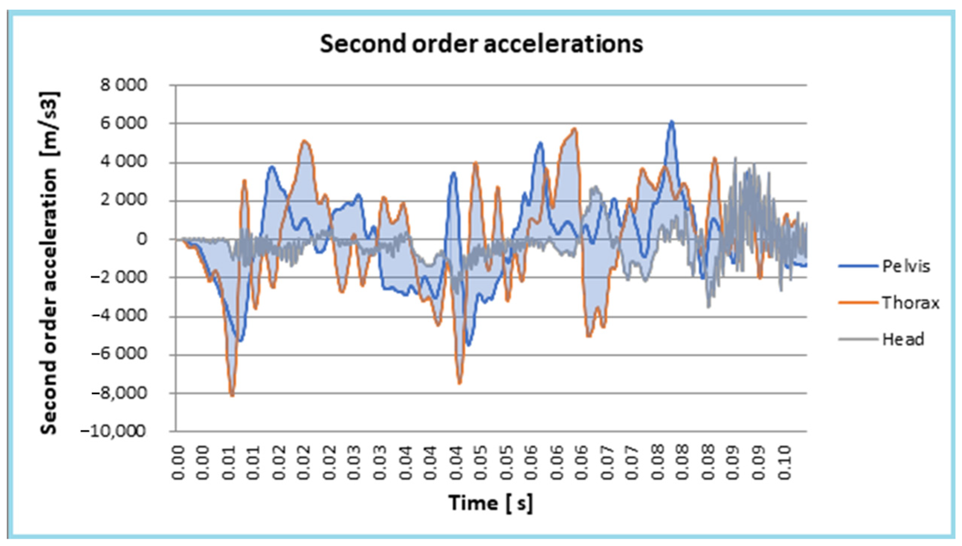
2.1. Second-Order Acceleration and Energy of Acceleration

Position of a point M became, after a deformation, M′, with the expression:
{ r M } G = { r O } G + [ R O T ] ( { r } L + { u } L ) .
where { r M } G is the position vector of the point M′, { r O } G is the position vector of the point M, [ R O T ] is the rotation matrix and { u } L is the elastic displacement [58,59,60,61].
The elastic displacements are expressed using the shape functions [ N ] :
{ u } L = [ N ] { δ } L .
Differentiation of this equation results in the velocity:
{ v M } G = { r ˙ M } G = { r ˙ O } G + [ R O ˙ T ] { r } L + [ R O ˙ T ] [ N ] { δ } L + [ R O T ] [ N ] { δ ˙ } L .
The acceleration of the point is:
{ a M } G = { r ¨ O } G + [ R O ¨ T ] { r } L + [ R O ¨ T ] [ N ] { δ } L + 2 [ R O ˙ T ] [ N ] { δ ˙ } L + [ R O T ] [ N ] { δ ¨ } L .
and the second-order acceleration is:
{ a ˙ M } G = { r O } G + [ R O T ] { r } L + [ R O T ] [ N ] { δ } L + 3 [ R O ¨ T ] [ N ] { δ ˙ } L + 3 [ R O ˙ T ] [ N ] { δ ¨ } L + [ R O T ] [ N ] { δ } L .
The expression of the energy of acceleration for N material points with the masses m i and the accelerations a i is [60,61]:
E a = 1 2 i = 1 N m i a i 2 .
For a continuous solid body, this relation can be written as:
E a = 1 2 V ρ a 2 d V .
After introducing Equation (4) into Equation (7), the following equation was obtained:
E a = 1 2 V ρ a M 2 d V = 1 2 V ρ { a M } T { a M } d V = 1 2 V ρ ( { r ¨ O } G T + { r } L T [ R O ¨ T ] T + { δ } L T [ N ] T [ R O ¨ T ] T + 2 { δ ˙ } L T [ N ] T [ R O ˙ T ] T + { δ ¨ } L T [ N ] T [ R O T ] T ) x x ( { r ¨ O } G + [ R O ¨ T ] { r } L + [ R O ¨ T ] [ N ] { δ } L + 2 [ R O ˙ T ] [ N ] { δ ˙ } L + [ R O T ] [ N ] { δ ¨ } L ) d V

2.2. Gibbs–Appell Formalism

The Gibbs–Appell equations can be expressed as [59]:
E a q ¨ j = Q j j = 1 , n ¯ .
Equation (8) includes the following terms [60,61]:
  • E a 2 is the part of the energy of acceleration that includes only quadratic terms:
    E a 2 = 1 2 V ρ ( { δ ¨ } L T [ N ] T [ N ] { δ ¨ } L ) d V ;
  • E a 1 is the part that includes linear terms:
    E a 1 = V ρ ( { δ ¨ } L T [ N ] T [ R O T ] T { r ¨ O } + { δ ¨ } L T [ N ] T [ R O T ] T [ R O ¨ T ] { r } L + { δ ¨ } L T [ N ] T [ R O T ] T [ R O ¨ T ] [ N ] { d } L + 2 { δ ¨ } L T [ N ] T [ R O T ] T [ R O ˙ T ] [ N ] { δ ˙ } L ) ) d V
  • E a 0 is the part of the energy of acceleration without { δ ¨ } L terms.
If we take into account our notations, Equation (9) can be written as:
{ E a δ ¨ } L { Q } L = 0 ;  
The term E a is:
E a = E a o ( q ˙ ) + E a 1 ( q ˙ , q ¨ ) + E a 2 ( q ¨ ) ;  
and:
{ Q } L = [ k ] { δ } L + { q } L + { q * } L ;
If we differentiate it, we obtain:
E a 2 { δ ¨ } L = ( V ρ [ N ] T [ S ] d V ) { d ¨ } L = [ m ] { δ ¨ } L ;
E a 1 { δ ¨ } L = [ m O i ] { r ¨ O } L { q i ( ω ) } { q i ( ε ) } + ( [ k ( ω ) ] + [ k ( ε ) ] ) { δ } L + [ c ] { δ } L ;
E a 0 { δ ¨ } L = 0 .
After performing the calculations, we obtain:
[ m ] { δ ¨ } L + [ c ] { δ ˙ } L + ( [ k ] + [ k ( ε ) ] + [ k ( ω ) ] ) { δ } L = { q } L + { q * } L { q i ( ε ) } L { q i ( ω ) } L [ m O i ] { r ¨ O } L
In Equation (18), [ m ] represents the mass matrix, [ c ] represents the damping matrix, [ k ] represents the stiffness matrix, [ k ( ε ) ] represents the stiffness due to the angular acceleration, [ k ( ω ) ] represents the stiffness due to the angular velocity, { q } L + { q * } L represents the concentrated and distributed forces and { q i ( ε ) } L { q i ( ω ) } L [ m O i ] { r ¨ O } represents the inertia forces.

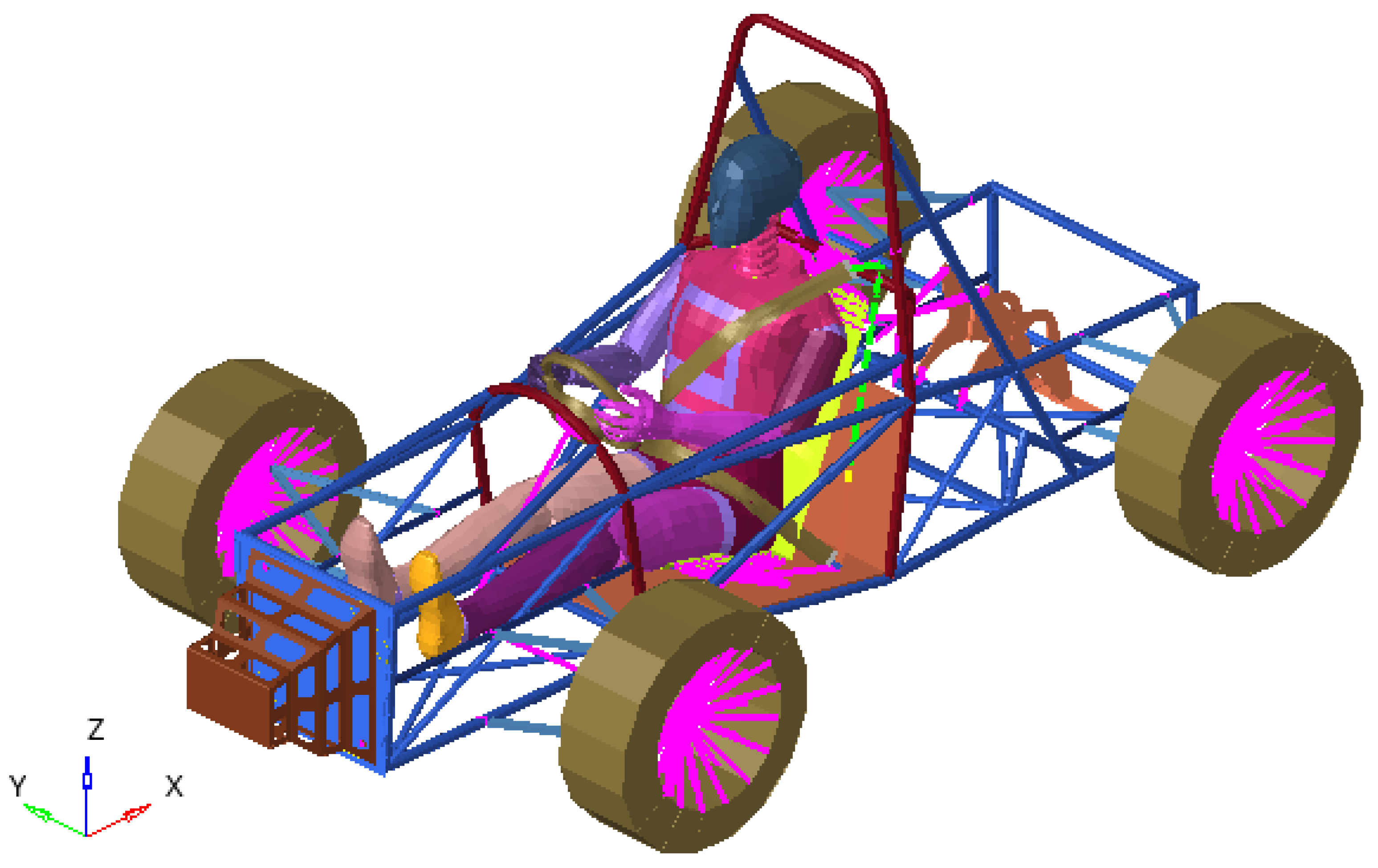
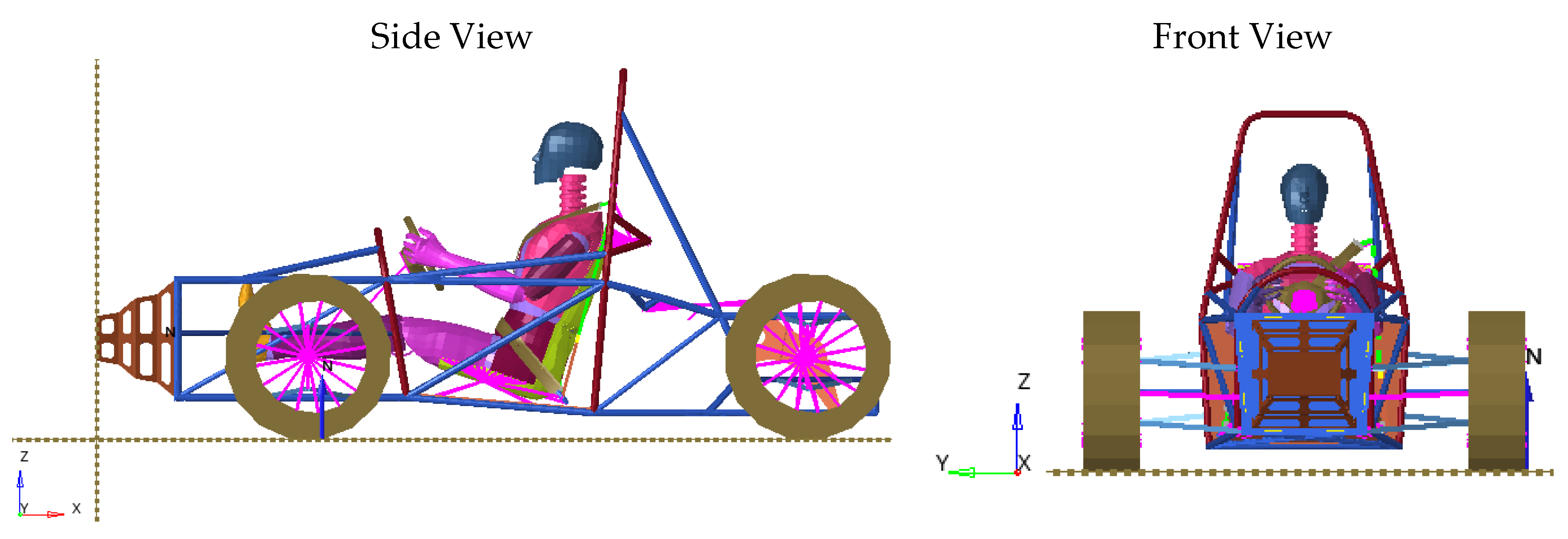
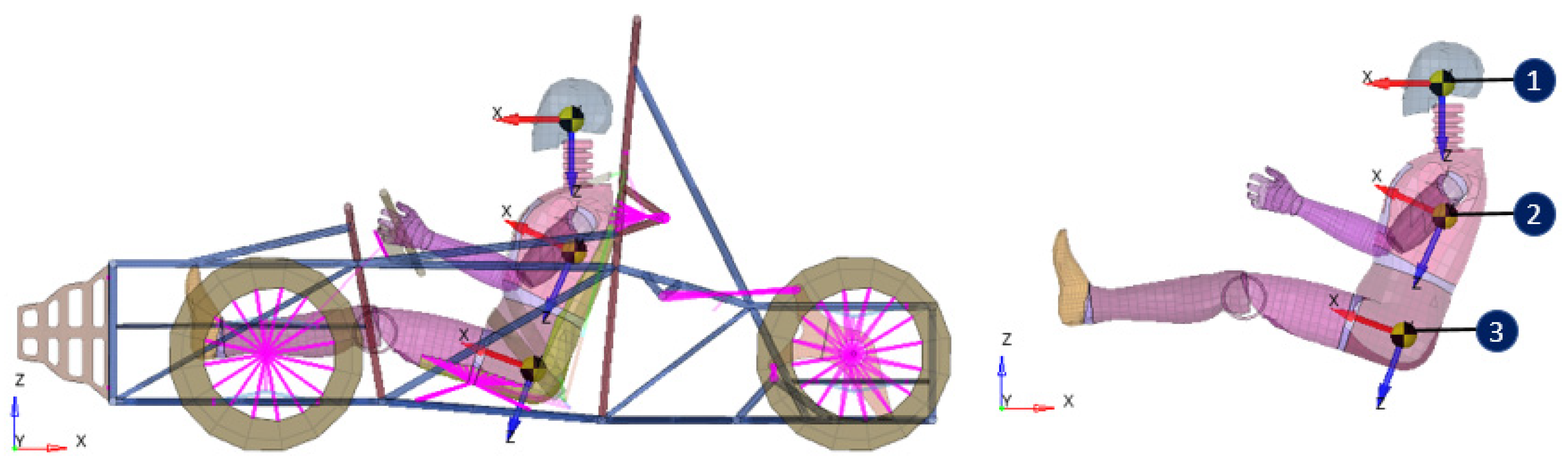
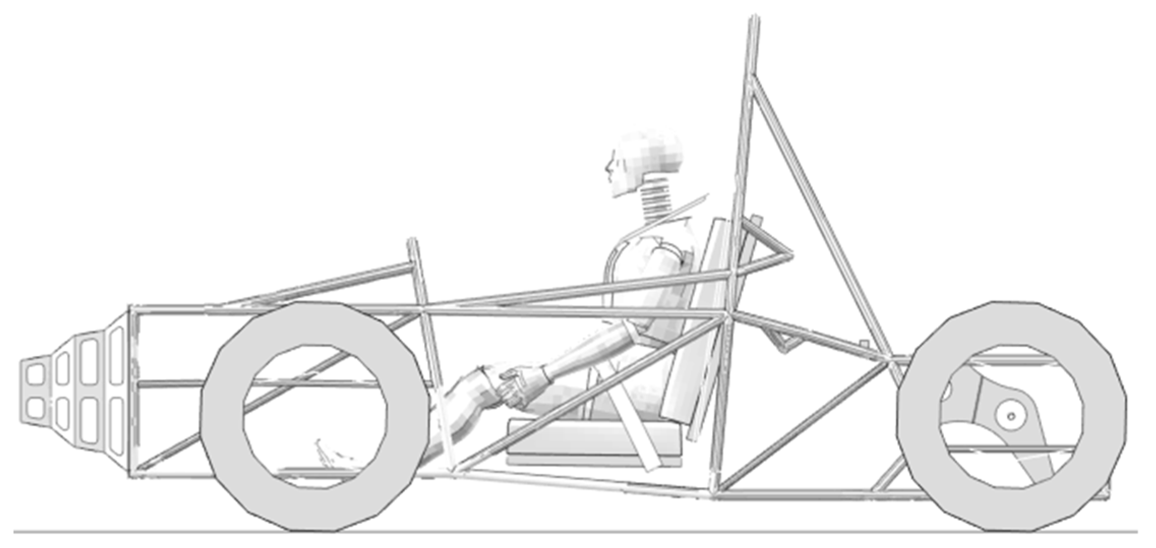
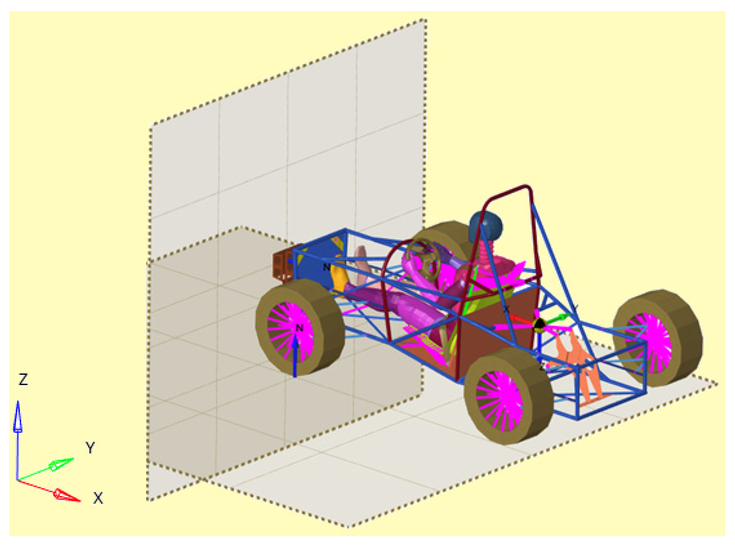
3. Numerical Model of a Race Car
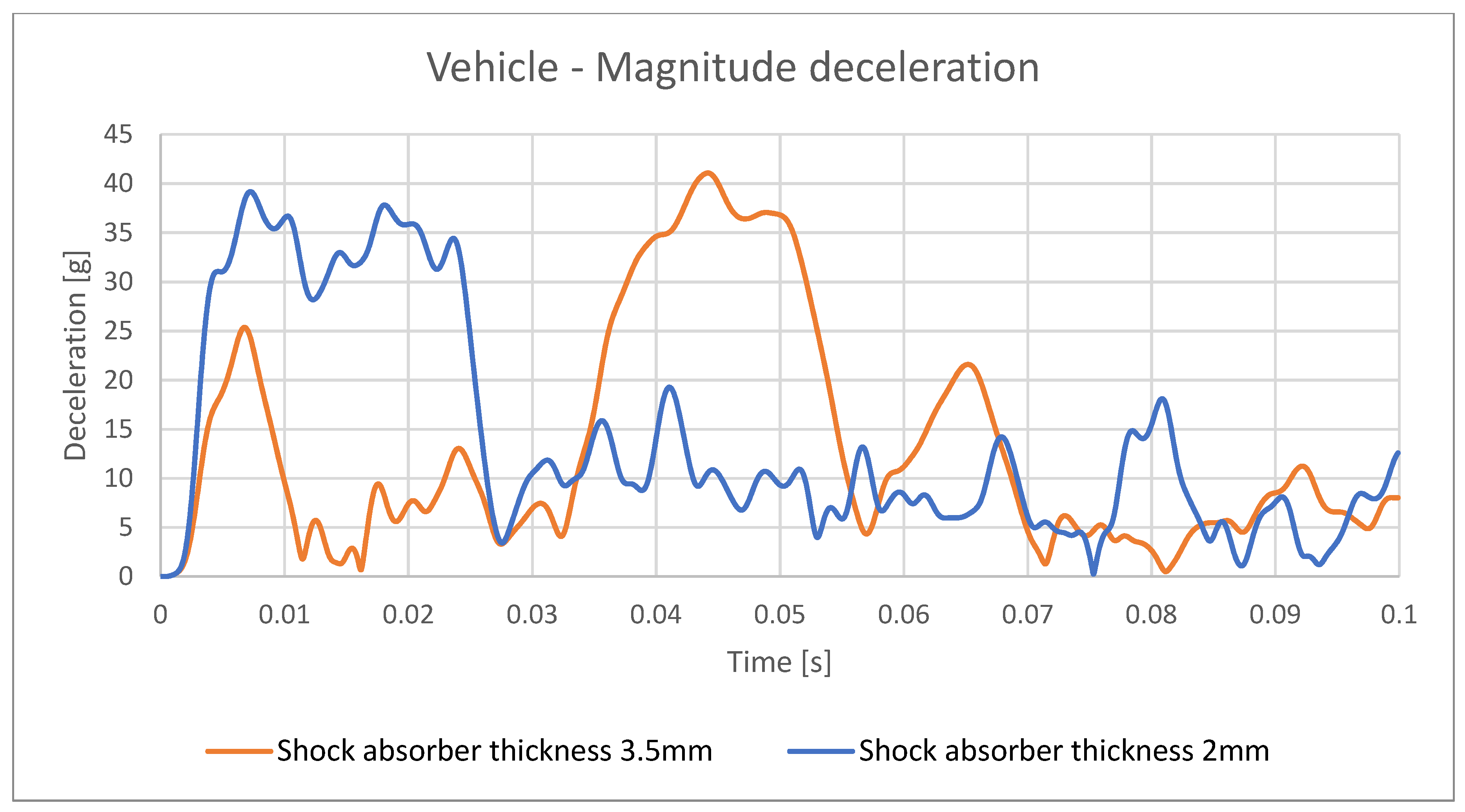
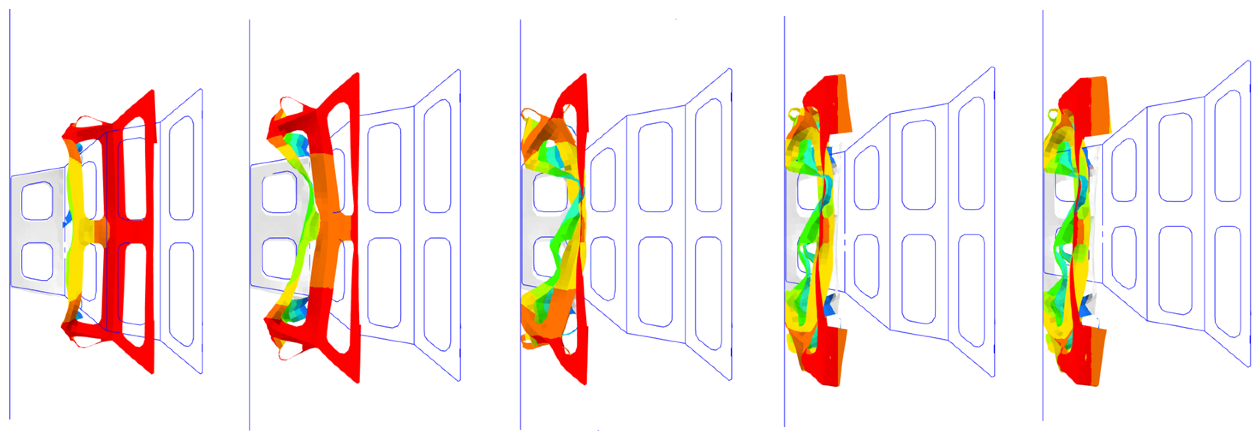
In general, man can be considered a fragile creature that is very sensitive to the various requests that may arise from the environment. His vulnerability to blows, impacts or accelerations is really high. In the event of an accident, the shocks are very large and can negatively affect the health of the people in the vehicle.
The automotive industry developed a system to protect the driver and passengers as much as possible. These efforts have focused on the human body. However, we do not have a real human body with which to test systems and conduct experiments. It is very clear that the subject would perish in the simulation of a real accident. As a result, alternatives to this problem were sought and the first solution was to use corpses, the closest substitutes available for a living person. They allow some results to be obtained, but the data obtained are ineffective. Animals have been used in some research, but the results are not reliable and the difference compared to humans is too pronounced. As a result, the use of anthropomorphic test devices, called current dummies, have been used.
Over time, the continuous evolution of these “dummies” has taken place, creating models closer and closer to the human body. The main disadvantage is that, although they are very precise from the point of view of kinematics and can provide values very close to the truth of the accelerations, it is difficult to specify the real demands placed on the human and the potential to harm his body, with possible serious consequences. Dummies with improved biofidelity and a greater possibility to perform measurements were created for this purpose. Thus, “frontal impact dummies”, “side impact dummies” and “aerospace dummies” were created. Of course, different models were created for men, women and children. Most research uses a standard adult mannequin of average size, having the average height and weight of the US adult male population. In the following, we studied the effects of the seat belt and shock absorber on the occupant of the vehicle using a model consisting of a dummy and a racing car [62,63,64]. The FE model that was analyzed is shown in Figure 1. This FE model contains the kart structure with a shock absorber (called an impact attenuator) placed at the front of the structure and a dummy fixed on a chair with a belt system connected in three points.
The goal of the absorber is to diminish the energy of impact transmitted to the dummy after a frontal crash with a rigid wall. The dummy used in FEA crash analysis is a Hybrid III 50th Male FE type. The Hybrid III 50th Percentile Male Crash Test Dummy represents the average adult male and is the most widely used crash test dummy in the world for the evaluation of automotive safety restraint systems in frontal crash testing [65].
The design solution of this shock absorber used in the analysis is shown in Figure 1 and Figure 2. We studied two versions of impact attenuators: one with a thickness of 2 mm and one with a thickness of 3.5 mm.
This study is based on an FEM model using Altair Hyperworks and a racing car that is used in Formula Student (Figure 1). Based on this design, the car is equipped with a shock absorber at the front, which has the role of absorbing shocks in the event of a frontal collision, and with a seat belt that acts on a dummy located in the car (Figure 3) [65,66,67,68]. More interesting parameters can be used in the analysis using the results presented in [69].
Figure 4 shows a square shock absorber system made of a metal sheet that is 2 mm thick that equips the studied racing car. This shock absorber has the role of taking over most of the shock suffered by the driver in the frontal collision.
The material that was used for the shock absorber was carbon steel. The mechanical properties of this material are as follows: a Young Modulus of 200 GPa; a Poison ratio of 0.3; a Tensile Yield Strength of 315 MPa; an Ultimate Tensile Strength of 438 MPa; and an elongation at break of 30%.
The kart structure, consisting of bars that form the chassis assembly, was modeled with first order shell elements with four corner nodes. Every node had six DOFs. The connections between all the bars of the kart structure were made using a common nodes technique. The engine mass was added as a lumped mass and was connected to the structure through rigid body elements RBE2. The shock absorber was modeled using shell elements.
Normally the feet are supported by the pedal support plate. This was not included in the simulation because it is not relevant for the analyses performed. Normally, after the impact, contact between the feet and pedal supports are lost and the tendency of the driver’s feet is to move towards the impact zone in an acceleration sense (x-axis).
This mechanical system was subjected to a frontal shock (Figure 5) following contact between the car and a front wall, after which the car stopped completely. As a result of this shock, large accelerations appear at different points on the dummy.
The preprocessing stage of the FE model was performed using Hypermesh and the post processing was performed with Hyperview. Both of these software programs were included in the ALTAIR Hyperworks package. The running crash impact simulation of the kart was performed using the RADIOSS solver, which can be considered as an analysis solution to evaluate and optimize product performance for highly nonlinear problems under dynamic loadings.
Moreover, it is known that RADIOSS is a solver solution especially dedicated for different applications, such as crash and safety, shock and impact analyses, drop tests, blast and explosion effects and high-velocity impacts.
To have information about dummy behavior after a frontal impact, three virtual accelerometers were considered on the dummy in the next location (the head, thorax and pelvis).
The impact velocity of a kart structure with a rigid wall was 7 m/s (25.2 kph). According to the rules of the Formula Student competition, the impact velocity request for virtual and real testing is 7 m/s (25.2 km/h) and in our analysis this velocity was increased in order to consider this as a risk factor.

4. Results

Figure 6 depicts the model of the race car with the “frontal impact dummy” of the Hybrid III 50th Male FE type (see Figure 3 and [65]).
The behavior of the system, at different moment in time, are presented in Figure 7.
Figure 8 presents the forces in the thorax and pelvis belts when they are used with an attenuator with a width of 2 mm. Figure 9 presents the forces in the thorax and pelvis belts when they are used with an attenuator with a width of 3.5 mm. The width refers to the width of the metallic material used for the impact attenuator.
Figure 10, Figure 11, Figure 12, Figure 13, Figure 14, Figure 15 and Figure 16 depict front views of the dummy, the belt and the distribution of stress on the belt (in every figure the maximum stress in MPa is presented in the rectangle). The maximum value of stress is mentioned in every figure.
After analyzing Figure 10, Figure 11, Figure 12, Figure 13, Figure 14, Figure 15 and Figure 16, we found that in some areas of the seat belt, the stress was higher than the admissible stress, but only in the final part of the period of time in which the event occurs and only for a very short interval. Our study did not consider the effects of airbags nor all the phenomena occurring before the moment of the airbag action. Figure 17, Figure 18 and Figure 19 present the decelerations that were determined using a virtual accelerometer placed on the dummy’s pelvis, thorax and head.
The behavior of the vehicle and its alignment to the acceptance criteria, according to the Formula Student Rules T3.19.1/2022 Version: 0.9, was studied. The model of the car is presented in Figure 20.
The obtained peak deceleration was 40 g and the average deceleration was 20 g, which respects the aforementioned criteria (Figure 21). Figure 22 presents the deformed impact attenuator at different points in time. Figure 23 depicts the second-order accelerations.

5. Discussion and Conclusions

The paper aims to determine the behavior of a passenger who is tied with a seat belt in a vehicle that is equipped with a shock absorber in the front. Furthermore, the forces appearing in the seat belt and the impact attenuator are also presented. Modeling with FEM was used in order to determine the loads to which the passenger was subjected. Determination of the forces that appeared during the shock was performed using the Gibbs–Appell method. The use of a 3.5 mm attenuator proves to be better from the passenger’s point of view. The maximum force in the belt and, therefore, the demands on the passenger’s body were lower than when a 2 mm attenuator was used. Moreover, for the 2 mm attenuator, there were two moments in which the stress in the tension strap was very high, so the effect on the passenger’s body was worse. The aim of this paper was not to determine the biological effects of accelerations and second-order accelerations on the human body during a frontal collision, but the values obtained can be used by researchers in the field. The severity of injury can be estimated based on the clearance or interference between dummy and the parts with which it came into contact with after the impact. For the example presented in the paper (of a dummy in a race car), the results show that the criteria for Formula Student Rules are respected.
The results obtained in the paper open a wide research horizon since the behavior of the driver or passenger is determined by many factors and current descriptions in the literature are still insufficient. These results may be useful for designers to see if the system can ensure minimum safety in a race. The modeling of a real racing car that is used in competitions by university students was used in the paper to obtain valuable information. We signal that numerous problems remain open for further study, such as the study of a belt fixed at four points or the study of the biological effects of the accelerations sustained by the driver or passenger.
The problem studied in the work requires future development and is imposed by the complexity of the problem addressed, which involves several fields of interest. In addition to the very complex and elaborate mechanical modeling, studies that investigate the biological behavior of the dummy used for modeling are needed.

Author Contributions

Conceptualization, C.I., A.T., L.-V.M. and S.V.; Formal analysis, A.T., L.-V.M. and S.V.; Investigation, C.I. and A.T.; Methodology, C.I. and S.V.; Software, C.I.; Supervision, C.I., A.T., L.-V.M. and S.V.; Validation, C.I., L.-V.M. and S.V.; Visualization, C.I., L.-V.M. and S.V.; Writing—original draft, S.V.; Writing—review & editing, S.V. All authors have read and agreed to the published version of the manuscript.

Funding

This research received no external funding.

Data Availability Statement

Not applicable.

Conflicts of Interest

The authors declare no conflict of interest.

References

  1. Ashley, S. Mechanical Seat-Belt Tensioner. Mech. Eng. 1992, 114, 24. [Google Scholar]
  2. DeGaspari, J. ‘Smarter’ seat belt fiber. Mech. Eng. 2002, 124, 22–30. [Google Scholar]
  3. Takimizu, Y. Retraction performance of motor vehicle seat belt. J. Jpn. Soc. Tribol. 1997, 42, 625–630. [Google Scholar]
  4. Sances, A.; Kumaresan, S.; Herbst, B.; Meyer, S.; Hock, D. Biomechanics of seat belt restraint system. In Proceedings of the 41st Annual Rocky Mountain Bioengineering Symposium/41st International ISA Biomedical Sciences Instrumentation Symposium, Ft Collins, CO, USA, 23–25 April 2004; Volume 449, pp. 377–380. [Google Scholar]
  5. Shi, P.C.; Xu, Z.W. Analysis of Seat. In Proceedings of the 5th Annual International Conference on Material Science and Environmental Engineering (MSEE 2017), Xiamen, China, 15–17 October 2017; Volume 301, p. 012127. [Google Scholar] [CrossRef]
  6. Huston, R.L. A Review of the effectiveness of seat belt systems: Design and safety considerations. Int. J. Crashworthiness 2001, 6, 243–252. [Google Scholar] [CrossRef]
  7. Zhao, F.; Jiao, H.Y. Topography Optimization of Automobile Seat Belt Bracket. the 2017 International Conference on Mechanical, Electronic, Control and Automation Engineering (MECAE 2017), Beijing, China, 25–26 March 2017; Volume 61, pp. 10–14. [Google Scholar]
  8. Dubois, D.; Gross, P.; Tramecon, A.; Markiewicz, E. Finite element analysis of seat belt bunching phenomena. Int. J. Crashworthiness 2006, 11, 519–528. [Google Scholar] [CrossRef]
  9. Kang, S.J.; Chun, B.K. Strength analysis of automotive seat belt anchorage. Int. J. Veh. Des. 2001, 26, 496–508. [Google Scholar] [CrossRef]
  10. Roberts, A.; Partain, M.; Batzer, S.; Renfroe, D. Failure analysis of seat belt buckle inertial release. Eng. Fail. Anal. 2007, 14, 1135–1143. [Google Scholar] [CrossRef]
  11. Dubois, D.; Zellmer, H.; Markiewicz, E. Experimental and numerical analysis of seat belt bunching phenomenon. Int. J. Impact Eng. 2009, 36, 763–774. [Google Scholar] [CrossRef]
  12. Cao, L.G.; Feng, H. Torque performance measurement system for spring in seat belt. In Proceedings of the 3rd International Conference on Advances in Materials Manufacturing (ICAMMP 2012), Beihai, China, 22–23 December 2012; Volume 655–657, pp. 1149–1152. [Google Scholar] [CrossRef]
  13. Tang, Y.M.; Lv, N.; Xue, Q.; Wang, T.; Tan, W.F. Experiment Simulation of Seat Belt and ISOFIX Anchorage for a Commercial Vehicle. In Proceedings of the 8th International Conference on Measuring Technology and Mechatronics Automation (ICMTMA), Macau, China, 11–12 March 2016; pp. 282–285. [Google Scholar] [CrossRef]
  14. Jung, S.P.; Park, T.W.; Park, C.S. Dynamic analysis and design optimisation of the seat belt pretensioner. Veh. Syst. Dyn. 2010, 48, 65–78. [Google Scholar] [CrossRef]
  15. Meyer, S.E.; Hock, D.; Forrest, S.; Herbst, B. Motor vehicle seat belt restraint system analysis during rollover. In Proceedings of the 40th Annual Rocky Mountain Bioengineering Symposium/40th International ISA Biomedical Sciences Instrumentation Symposium, Biloxi, MS, USA, 10–13 April 2003; Volume 39, pp. 229–240. [Google Scholar]
  16. Karishma, P.; Venugopal, K.V.; Raju, I.R.K. Optimization and Impact Analysis of a Roll Cage Model. Int. Res. J. Eng. Technol. (IRJET) 2018, 5, 526–543. [Google Scholar]
  17. Kanketr, T.; Phongphinnittana, E.; Patamaprohm, B. Design of a CFRP composite monocoque: Simulation approach. In Proceedings of the 9th Thai-Society-of-Mechanical-Engineers International Conference on Mechanical Engineering (TSME-ICoME), Phuket, Thailand, 11–14 December 2018; IOP Conference Series-Materials Science and Engineering. Volume 501, p. 012014. [Google Scholar] [CrossRef]
  18. Lufinka, A. Crash Test of the Student Racing Car Impact Attenuator. In Proceedings of the 58th International Conference of Machine Design Departments (ICMD 2017), Prague, Czech Republic, 6–8 September 2017; pp. 210–213. [Google Scholar]
  19. Kaul, A.; Abbas, A.; Smith, G.; Manjila, S.; Pace, J.; Steinmetz, M. A revolution in preventing fatal craniovertebral junction injuries: Lessons learned from the Head and Neck Support device in professional auto racing. J. Neurosurgey-Spine 2016, 25, 756–761. [Google Scholar] [CrossRef] [PubMed] [Green Version]
  20. Mihradi, S.; Golfianto, H.; Mahyuddin, A.I.; Dirgantara, T. Head Injury Analysis of Vehicle Occupant in Frontal Crash Simulation: Case Study of ITB’s Formula SAE Race Car. J. Eng. Technol. Sci. 2017, 49, 534–545. [Google Scholar] [CrossRef]
  21. Guegan, P.; Lebreton, D.; Pasco, F.; Othman, R.; Le Corre, S.; Poitou, A. Metallic energy-absorbing inserts for Formula One tyre barriers. Proceeding Inst. Mech. Eng. Part D-J. Automob. Eng. 2008, 222, 699–704. [Google Scholar] [CrossRef] [Green Version]
  22. Davies, H.C.; Bryant, M.; Hope, M.; Meiller, C. Design, development, and manufacture of an aluminium honeycomb sandwich panel monocoque chassis for Formula Student competition. Proceeding Inst. Mech. Eng. Part D-J. Automob. Eng. 2012, 226, 325–337. [Google Scholar] [CrossRef] [Green Version]
  23. Albak, E.I.; Solmaz, E.; Kaya, N.; Ozturk, F. Impact attenuator conceptual design using lightweight materials and meta-modeling technique. Mater. Test. 2019, 61, 621–626. [Google Scholar] [CrossRef]
  24. Switek, W.; Vallejo, R. Finite element dynamic simulation of a race car. In Proceedings of the Computer Aided Optimum Design of Structures VIII, Structures and Materials, Proceedings of the 8th International Conference on Computer Aided Optimum Design of Structures, Dearborn, MI, USA, 19–21 May 2003; WIT Press: Southampton, UK; Volume 13, pp. 115–122.
  25. Nguyen, H.C.; Vo-Minh, T. The use of the node-based smoothed finite element method to estimate static and seismic bearing capacities of shallow strip footings. J. Rock Mech. Geotech. Eng. 2022, 14, 180–196. [Google Scholar] [CrossRef]
  26. Iorio, L. Revisiting the 2PN Pericenter Precession in View of Possible Future Measurements. Universe 2020, 6, 53. [Google Scholar] [CrossRef]
  27. Negrean, I. Formulations about Elastodynamics in Robotics. Acta Tech. Napoc. Ser. Appl. Math. Mech. Eng. 2019, 62, 237–250. [Google Scholar]
  28. Hassan, M.; Bruni, S. Experimental and numerical investigation of the possibilities for the structural health monitoring of railway axles based on acceleration measurements. Struct. Health Monit. Int. J. 2019, 18, 902–919. [Google Scholar] [CrossRef]
  29. Xiao, M.L.; Zhang, Y.; Zhu, H.Y. The mechanism of hindering occupants’ evacuation from seismic responses of building. Nat. Hazards 2019, 96, 669–692. [Google Scholar] [CrossRef]
  30. Ma, S.J.; Xu, X.X.; Huang, P.T.; Hu, L.Y. The discussion on Lagrange equation containing third order derivatives. Acta Phys. Sin. 2004, 53, 3648–3651. [Google Scholar]
  31. Krut’ko, P.D. Energy damping problems and control algorithms of motion of dynamical systems. Nonlinear models. J. Comput. Syst. Sci. Int. 1999, 38, 841–859. [Google Scholar]
  32. Kim, C.J.; Kang, Y.J.; Lee, B.H. Experimental spectral damage prediction of a linear elastic system using acceleration response. Mech. Syst. Signal Processing 2011, 25, 2538–2548. [Google Scholar] [CrossRef]
  33. Krutko, P.D. Control of the motion of Lagrangian systems. Synthesis of algorithms by the method of the inverse problems of dynamics. J. Comput. Syst. Sci. Int. 1996, 34, 77–94. [Google Scholar]
  34. Berges, C.; Weber, Y.; Soufflet, P. General linearized model use for High Power Reliability Assessment test results: Conditions, procedure and case study. Microelectron. Reliab. 2015, 55, 1346–1350. [Google Scholar] [CrossRef]
  35. Stachiw, T.; Khouli, F.; Langlois, R.G.; Afagh, F.F. Linearization of Aircraft Landing Equations of Motion with Airframe Flexibility Effects. SAE Int. J. Aerosp. 2022, 15, 19–38. [Google Scholar] [CrossRef]
  36. Ledezma-Ramirez, D.F.; Guzman-Nieto, M.; Tapia-Gonzalez, P.E.; Ferguson, N.S. Shock isolation systems using non linear stiffness and damping. Proceedings of International Conference on Noise and Vibration Engineering (ISMA2014) and International Conference on Uncertainty in Structural Dynamics (USD2014), Leuven, Belgium, 15–17 September 2014; pp. 4111–4121. [Google Scholar]
  37. Kim, K.H.; Yoh, J. Multi-physics modeling based on combustion of energetic materials. Explosion, Shock Wave and Hypervelocity Phenomena in Materials. In Materials Science Forum; Materials II, Book Series; Trans Tech Publications Ltd.: Bäch, Switzerland, 2008; Volume 566, pp. 95–100. [Google Scholar] [CrossRef]
  38. Murthy, A.N.; Pfabe, M.; Xu, J.F.; Talke, F.E. Dynamic response of 1-in. form factor disk drives to external shock and vibration loads. Microsyst. Technol. 2007, 13, 1031–1038. [Google Scholar] [CrossRef]
  39. Clegg, R.A.; Hayhurst, C.J.; Nahme, H. Validation of an advanced material model for simulating the impact and shock response of composite materials. AIP Conf. Proc. 2002, 620, 685–688. [Google Scholar] [CrossRef]
  40. Hundal, M.S. Linear Shock Isolator—Response to Velocity Pulse. J. Sound Vib. 1983, 86, 293–296. [Google Scholar] [CrossRef]
  41. Hill, R.J.; Boratav, O.N. Next-order structure-function equations. Phys. Fluids 2001, 13, 276–283. [Google Scholar] [CrossRef]
  42. Alghafir, M.N.; Dunne, J.F. A NARX damper model for virtual tuning of automotive suspension systems with high-frequency loading. Veh. Syst. Dyn. 2012, 50, 167–197. [Google Scholar] [CrossRef]
  43. Wheaton, B.J.; Maybeck, P.S. 2nd-Order Acceleration Models for an MMAE Target Tracker. IEEE Trans. Aerosp. Electron. Syst. 1995, 31, 151–167. [Google Scholar] [CrossRef] [Green Version]
  44. Djenidi, L.; Antonia, R.A. Modeling the third-order velocity structure function in the scaling range at finite Reynolds numbers. J. Math. Phys. 2021, 62, 083102. [Google Scholar] [CrossRef]
  45. Owen, H.; Codina, R. A third-order velocity correction scheme obtained at the discrete level. Int. J. Numer. Methods Fluids 2012, 69, 57–72. [Google Scholar] [CrossRef]
  46. Filben, T.M.; Pritchard, N.S.; Oravec, C.S.; Hile, C.W.; Bercaw, J.R.; Zoch, S.R.; Miller, L.E.; Bullock, G.S.; Flashman, L.A.; Miles, C.M.; et al. Pilot characterization of head kinematics in grassroots dirt track racing traffic injury prevention. Traffic Inj. Prev. 2022, in press. [Google Scholar] [CrossRef]
  47. Bhat, A.; Gupta, V.; Aulakh, S.S.; Elsen, R.S. Generative design and analysis of a double-wishbone suspension assembly: A methodology for developing constraint oriented solutions for optimum material distribution. J. Eng. Des. Tecnol. 2021, in press. [Google Scholar] [CrossRef]
  48. Drage, T.; Lim, K.L.; Koh, J.E.H.; Gregory, D.; Brogle, C.; Braunl, T. Integrated Modular Safety System Design for Intelligent Autonomous Vehicles. In Proceedings of the 2021 IEEE Intelligent Vehicles Symposium (IV), Nagoya, Japan, 11–17 July 2021; pp. 258–265. [Google Scholar] [CrossRef]
  49. Vaverka, O.; Koutny, D.; Palousek, D. Topologically optimized axle carrier for Formula Student produced by selective laser melting. Rapid Prototyp. J. 2019, 25, 1545–1551. [Google Scholar] [CrossRef]
  50. Vlase, S.; Teodorescu, P.P. Elasto-Dynamics of a Solid with a General “RIGID” Motion using FEM Model. Part I. Theoretical Approach. Rom. J. Phys. 2013, 58, 872–881. [Google Scholar]
  51. Vlase, S.; Negrean, I.; Marin, M.; Scutaru, M.L. Energy of Accelerations Used to Obtain the Motion Equations of a Three-Dimensional Finite Element. Symmetry 2020, 12, 321. [Google Scholar] [CrossRef] [Green Version]
  52. Gibbs, J.W. On the fundamental formulae of dynamics. Am. J. Math. 1879, 2, 49–64. [Google Scholar] [CrossRef]
  53. Appell, P. Sur une forme générale des equations de la dynamique. C.R. Acad. Sci. Paris 1899, 129, 317–320. [Google Scholar]
  54. Mirtaheri, S.M.; Zohoor, H. The Explicit Gibbs-Appell Equations of Motion for Rigid-Body Constrained Mechanical System. In Proceedings of the RSI International Conference on Robotics and Mechatronics ICRoM, Piscataway, NJ, USA, 23–25 October 2018; pp. 304–309. [Google Scholar]
  55. Korayem, M.H.; Dehkordi, S.F. Motion equations of cooperative multi flexible mobile manipulator via recursive Gibbs-Appell formulation. Appl. Math. Model. 2019, 65, 443–463. [Google Scholar] [CrossRef]
  56. Shafei, A.M.; Shafei, H.R. A systematic method for the hybrid dynamic modeling of open kinematic chains confined in a closed environment. Multibody Syst. Dyn. 2017, 38, 21–42. [Google Scholar] [CrossRef]
  57. Korayem, M.H.; Dehkordi, S.F. Derivation of dynamic equation of viscoelastic manipulator with revolute-prismatic joint using recursive Gibbs-Appell formulation. Nonlinear Dyn. 2017, 89, 2041–2064. [Google Scholar] [CrossRef]
  58. Vlase, S.; Marin, M.; Scutaru, M.L. Maggi’s equations used in the finite element analysis of the multibody systems with elastic elements. Mathematics 2020, 8, 399. [Google Scholar] [CrossRef] [Green Version]
  59. Ursu-Fisher, N. Elements of Analytical Mechanics; House of Science Book Press: Cluj-Napoca, Romania, 2015. [Google Scholar]
  60. Negrean, I.; Crișan, A.-D.; Vlase, S. A New Approach in Analytical Dynamics of Mechanical Systems. Symmetry 2020, 12, 95. [Google Scholar] [CrossRef] [Green Version]
  61. Vlase, S.; Negrean, I.; Marin, M.; Nastac, S. Kane’s Method-Based Simulation and Modeling Robots with Elastic Elements, Using Finite Element Method. Mathematics 2020, 8, 805. [Google Scholar] [CrossRef]
  62. European New Car Assessment Programme (Euro NCAP), Frontal Impact Testing Protocol Version 6.0 August 2012. Available online: https://cdn.euroncap.com/media/1478/euro-ncap-side-protocol-version-60.pdf (accessed on 27 August 2022).
  63. The Biofidelity of Hybrid III Dummies, Dimitrios Kallieris, Andreas Rizzetti, Rainer Mattern, Institute of Legal Medicine University of Heidelberg. Available online: http://www.ircobi.org/wordpress/downloads/irc1995/pdf_files/1995_10.pdf (accessed on 27 August 2022).
  64. Injury Criteria for Side Impact Dummies, May 2004, By Shashi Kuppa National Transportation Biomechanics Research Center National Highway Traffic Safety Administration. Available online: https://www.nhtsa.gov/DOT/NHTSA/NRD/Multimedia/PDFs/Biomechanics%20&%20Trauma/MiscBio/NPRM_SID.pdf (accessed on 27 August 2022).
  65. Hybrid III 50th Male FE|Humanetics. Available online: humaneticsgroup.com (accessed on 25 September 2022).
  66. Li, X. Simulation System of Car Crash Test in C-NCAP Analysis Based on an Improved Apriori Algorithm. Phys. Procedia 2012, 25, 2066–2071. [Google Scholar] [CrossRef] [Green Version]
  67. Martinez, M.J. Artificial Neural Networks for Passive Safety Assessment. Eng. Lett. 2022, 30, 289–297. [Google Scholar]
  68. Untaroiu, C.D.; Shina, J.; Ivarssona, J.; Crandalla, J.R.; Subita, D.; Takahashib, Y.; Akiyamab, A.; Kikuchi, Y. A study of the pedestrian impact kinematics using finite element dummy models: The corridors and dimensional analysis scaling of upper-body trajectories. Int. J. Crashworthiness 2008, 13, 469–478. [Google Scholar] [CrossRef]
  69. Bhatti, M.M.; Marin, M.; Zeeshan, A.; Abdelsalam, S.I. Recent trends in computational fluid dynamics. Front. Phys. 2020, 8, 593111. [Google Scholar] [CrossRef]
Figure 1. The car with a shock absorber and a seat belt. Aerial view.
Mathematics 10 03593 g001
Figure 2. The car with a shock absorber and a seat belt. Side and front view.
Mathematics 10 03593 g002
Figure 3. The dummy and the seat belt system (side and front view—Hybrid III 50th Male FE).
Mathematics 10 03593 g003
Figure 4. The shock absorber system.
Mathematics 10 03593 g004
Figure 5. Frontal collision of the car with a wall and the position of accelerometers (1—Head, 2—Thorax and 3—Pelvis).
Mathematics 10 03593 g005
Figure 6. The initial reference position.
Mathematics 10 03593 g006
Figure 7. Position after: (a) T = 0.025 s; (b) T = 0.050 s; (c) T = 0.075 s; (d) T = 0.10 s. The dimensions are in mm.
Mathematics 10 03593 g007aMathematics 10 03593 g007b
Figure 8. The forces in the thorax and pelvis belts. The shock absorber had a thickness of 2 mm.
Mathematics 10 03593 g008
Figure 9. The forces in the thorax and pelvis belts. The shock absorber had a thickness of 3.5 mm.
Mathematics 10 03593 g009
Figure 10. Stress in the belt when T = 0.015 s (in MPa).
Mathematics 10 03593 g010
Figure 11. Stress in the belt when T = 0.020 s (in MPa).
Mathematics 10 03593 g011
Figure 12. Stress in the belt when T = 0.025 s (in MPa).
Mathematics 10 03593 g012
Figure 13. Stress in the belt when T = 0.030 s (in MPa).
Mathematics 10 03593 g013
Figure 14. Stress in the belt when T = 0.035 s (in MPa).
Mathematics 10 03593 g014
Figure 15. Stress in the belt when T = 0.050 s (in MPa).
Mathematics 10 03593 g015
Figure 16. Stress in the belt when T = 0.055 s (in MPa).
Mathematics 10 03593 g016
Figure 17. Acceleration registered by a virtual accelerometer in the pelvis, v = 13 m/s.
Mathematics 10 03593 g017
Figure 18. Acceleration registered by a virtual accelerometer in the thorax, v = 13 m/s.
Mathematics 10 03593 g018
Figure 19. Acceleration registered by a virtual accelerometer in the head, v = 13 m/s.
Mathematics 10 03593 g019
Figure 20. The wall is the reference in the presentation.
Mathematics 10 03593 g020
Figure 21. Deceleration of the vehicle at a shock of 7 m/s.
Mathematics 10 03593 g021
Figure 22. Different positions of the deformed impact attenuator at the following times: 0.1 s; 0.2 s; 0.3 s; 0.4 s; 0.5 s.
Mathematics 10 03593 g022
Figure 23. Second-order accelerations.
Mathematics 10 03593 g023
Publisher’s Note: MDPI stays neutral with regard to jurisdictional claims in published maps and institutional affiliations.

