Article

Force Tracking Impedance Control of Hydraulic Series Elastic Actuators Interacting with Unknown Environment

1
The State Key Laboratory of Fluid Power and Mechatronic Systems, Zhejiang University, Hangzhou 310027, China
2
Hainan Instruction of Zhejiang University, Sanya 572025, China
3
Ocean College, Zhejiang University, Zhoushan 316021, China
4
No.2 Research Department, Wuhan Second Ship Design and Research Institute, Wuhan 430205, China
5
School of Mechanical Engineering, Shijiazhuang Tiedao University, Shijiazhuang 050043, China
*
Authors to whom correspondence should be addressed.
Mathematics 2022, 10(18), 3383; https://doi.org/10.3390/math10183383
Submission received: 10 August 2022 / Revised: 9 September 2022 / Accepted: 14 September 2022 / Published: 18 September 2022
(This article belongs to the Special Issue Dynamic Modeling and Simulation for Control Systems)

Abstract

:
Force tracking control for hydraulic series elastic actuators (SEAs) is the demand in robots interacting with the surrounding world. However, the inherent nonlinearities and uncertainties of the hydraulic system, as well as the unknown environment, make it difficult to achieve precise contact force control of hydraulic SEAs. Therefore, in this study, force tracking impedance control of hydraulic SEAs is developed considering interaction with an unknown environment in which the force tracking performance can be guaranteed in theory. Based on the typical force tracking impedance frame, the force tracking performance is improved by introducing backstepping control into the inner position controller to deal with the high-order nonlinear dynamics of the hydraulic SEA. In addition, the environment parameters are also estimated online by the adaptive method. Finally, comparative simulation is conducted with different interacting environments, which verifies the advantages of the proposed method.

1. Introduction

Force control has been the fundamental capacity and a hot topic research area for actuators due to its wider applications in industry and robot systems. These research issues may be broadly classified into two types: compliance and precision. For the case of compliance force control, this is commonly used in the collaboration between humans and robots, tele-robotic systems, and walking robots, which have been reported in the literature [1,2,3]. For the case of precise force control, this is usually applied in force loading simulation [4]. An important control method of compliance force control is impedance control presented in [5,6], which adjusts the contract force by using the relationship between force and position/velocity error. Impedance control avoids dangerousness when the actuators interact with the external environment. However, the force tracking performance is not satisfactory, especially in an unknown environment.
With the growing interest in providing force tracking capability for impedance control, force tracking impedance control was proposed by Seraji and Colbaugh [7]. The main contribution of this method presents accurate steady-state force tracking performance and flexibility when the external environment changes rapidly. Therefore, it is widely employed in hole operation, deburring, grinding, etc. A special device for precise force control is hydraulic series elastic actuators (SEAs), which are equipped with a spring between the power output shaft and the environment. The advantages of hydraulic SEAs can be summarized two aspects according to [8,9,10,11]. On the one hand, it provides high force fidelity, shock tolerance, and force sensing for interaction control. On the other hand, it enjoys the property of high power density compared with electric SEA. However, to our knowledge, the studies on the precise force tracking for hydraulic SEAs have not yet been established. In the existing literature, there is some research on modeling and controller design. Shen et al. [12] established the hydraulic SEAs model based on flow equations [13] and Newton’s second law. Then they applied the impedance method to the hydraulic series elastic actuator using an outer loop feedback position and inner feedback force to achieve force control. Mustalahti et al. [14] established a fifth-order state space model for the hydraulic SEAs considering the non-linear dynamics of hydraulic systems, and the full stated feedback position controller was designed. However, the environment was regarded as known and rigid, which decreased the application of the proposed control. Furthermore, the force tracking performance is not satisfactory in the above papers. In order to improve force performance, force tracking impedance control is an available method. The main difficulties applying this control method to the hydraulic SEAs are as follows. Firstly, a position tracking error due to unknown dynamic uncertainties of hydraulic systems should be minimized. Secondly, the controller must be robust enough to deal with unknown environment stiffness.
These problems will also emerge when applying the force tracking impedance to electronic SEAs. Many efforts have been made to solve these problems. For the of case control frame, Zhao et al. [15] proposed a controller design criterion, which is composed of outer impedance and inner torque feedback loops for SEAs. For the detail control methods, based on disturbance observer control is applicable with overcoming the model uncertainty. For instance, Oh and Kong [16] applied a disturbance observer and feedforward controller to achieve the high-precision force control for the SEA system by utilizing the two-mass dynamic model. Sun et al. [17] proposed nonlinear observer-based force control for electro-hydraulic actuators, which does not require the cylinder position and velocity information. In addition, adaptive control is another method to deal with the model uncertainties. Liu et al. [18] proposed a Lyapunov-based parameter adaption control algorithm to compensate for parameter uncertainties. Baigzadehnoe et al. [19] and Wang et al. [20] used the adaptive fuzzy control method to achieve the force/position hybrid control for a robot manipulator. However, these literature concentrate on the electrical drive machinery system using the motor torque control close-ring. Unfortunately, the hydraulic SEAs system generally does not have a force closed loop. This is because the hydraulic system behaves with higher nonlinearity, stronger parameter uncertainties, and a higher dynamic model compared with electronic SEAs. In spite of this, many control methods have been proposed to achieve precise position control for hydraulic systems, for example, adaptive control, robust control, adaptive robust control [21,22,23,24], disturbance control based on the extended state observer [25,26], backstepping control [27], the sign of the error (RISE) control [28], sliding mode control [29] and so on. These theories have not been integrated into force tracking control to achieve perfect force tracking performance. Moreover, the adaptive techniques using force tracking errors have been proposed to estimate environment parameters (stiffness and damping). Misra et al. [30,31] applied adaptive techniques to bilateral manipulators for estimating environment parameters. Calanca et al. [32] developed an environment-adaptive force controller by estimating the environment dynamics online and continuously adjusting the control law accordingly. These theories provide a basis for this paper.
The purpose of this paper is to propose a force tracking impedance control method for the hydraulic series elastic actuators. It is robust with respect to uncertainties in both hydraulic dynamic model and environment stiffness. The main idea is to minimize force error by using an advanced position controller and a parameter adaptive method for an unknown environment.
This paper is organized as follows. The dynamic model of the nonlinear hydraulic SEAs is derived in Section 2. Section 3 demonstrates the design of the force tracking impedance controller. In Section 4, the simulation utilizing a hydraulic SEAs system verifies the high performance of the proposed controller. The conclusion and further research are presented in Section 5.

2. Modeling of the Hydraulic Series Elastic Actuators

2.1. Hydraulic SEAs Modeling

The structure of single-rod electro-hydrostatic series elastic actuators is shown in Figure 1. The environment is represented by a linear spring and a damper. Thus, the mathematical dynamics model of hydraulic SEAs is represented [8] as follows:
m c y l x ¨ c y l + B c y l x ˙ c y l + K s ( x c y l x l o a d ) F 1 = 0 , m l o a d x ¨ l o a d + B e x ˙ l o a d + ( K s + K e ) x l o a d K s x c y l = 0 ,
where m c y l and m l o a d are the mass of the piston and load in [kg], respectively. x c y l and x l o a d are the position of the piston and load in [m], respectively; K s is the spring stiffness of SEA in [N/mm]; B c y l is the viscous damping coefficient of the piston in [Ns/m]; K e is a linear spring stiffness and B e a damping coefficient; and F 1 is the hydraulic driven force in [N].
The hydraulic driven force F 1 satisfies:
F 1 = P 1 A 1 P 2 A 2 , F ˙ 1 = α ( x c y l , t ) w p + β ( x c y l , t ) x ˙ c y l + φ ( x c y l , t ) F 1 + γ ( x c y l , x ˙ c y l ) ,
where P 1 , P 2 are the pressures of both chambers for hydraulic cylinders in [ N / m 2 ]; A 1 , A 2 are the areas of both chambers for hydraulic cylinders in [ m 2 ]; w P is the speed of the pump in [ rad / s ]; and α ( x c y l , t ) , β ( x c y l , t ) , and φ ( x c y l , t ) are the parameters of the pump control hydraulic cylinder satisfying [26]:
α ( x c y l , t ) = ( V 1 A 1 + V 2 A 2 ) β e D p ,
β ( x c y l , t ) = ( A 1 2 V 1 + A 2 2 V 2 ) β e ,
φ ( x c y l , t ) = ( 1 V 1 + 1 V 2 ) L P β e ,
where D P is the volumetric capacity of the pump in [ m 3 / rad ], L P is the total leakage coefficient of the pump and cylinder in [ m 5 / Ns ], β e is the effective bulk modulus of the systems in [ N / m 2 ], and V 1 ( x c y l ) = V A 0 + A 1 x c y l and V 2 ( x c y l ) = V B 0 A 2 x c y l are the volumes of chambers A and B in [ m 3 ], respectively. x c y l and x l o a d are physically bound as:
x l i m 1 x c y l x l i m 1 , x l i m 2 x l a o d x l i m 2 ,
where x l i m 1 , x l i m 2 are positive constants. The ranges of V 1 ( x c y l ) , V 2 ( x c y l ) are defined as:
V A 0 A 1 x l i m 1 = V A m i n V 1 ( x c y l ) V A m a x = V A 0 + A 1 x l i m 1 , V B 0 A 2 x l i m 1 = V B m i n V 2 ( x c y l ) V B m a x = V B 0 + A 2 x l i m 2 .
Remark 1.
In B c y l , K s , A 1 , A 2 , V 1 , and V 2 can be easily known because they are mechanically fixed parameters. However, the β e varies with the temperature and working time. In addition, considering the unmeasured states γ, the total model uncertainty can be defined as d 1 , including γ and Δ β e . The d 1 is also bounded since V A 0 , V B 0 , and x c y l are bounded.

2.2. Problem Formulation

The new state variable x is defined as:
x = x 1 x 2 x 3 x 4 x 5 = x l o a d x c y l x ˙ l o a d x ˙ c y l F 1 .
Form the relationships (1) and (2), the hydraulic cylinder dynamics are obtained as:
x ˙ 1 = x 3 , x ˙ 2 = x 4 , x ˙ 3 = B l o a d x 3 ( K s + K e ) x 1 + K s x 2 m l o a d , x ˙ 4 = B c y l x 4 K s ( x 2 x 1 ) + x 5 m c y l , x ˙ 5 = α ( x 2 , t ) w p + β ( x 2 , t ) x 4 + φ ( x 2 , t ) x 5 + d 1 .
The main goal in the controller design is the force tracking impedance control based on the advance position tracking control interacting with an unknown environment.

3. Force Tracking Impedance Control of SEAs Based on Dynamic Models

In this section, the force tracking impedance control is designed, which includes an inner position controller, environment estimation, and the desired impedance model. Its frame is shown in Figure 2. In this picture, some notations are defined as follows: x r and x c are the reference and commanded position trajectories, respectively. x P is the output of the desired impedance model. w p is the controller output. F r is the desired contact forces, F s is the hydraulic SEAs output torque computed by evaluating the spring displacement, and E is the force tracking error. F e is the actual contact force acting on the environment, which can be measured with force senors. F s and F e drive the load dynamic system.

3.1. Inner Position Controller Design

A precise position controller is fundamental for improving the force tracking performance. According to the dynamic model, the direct robust position control (DRC) is designed via the backstepping method to deal with the high-order dynamics and nonlinearities of the hydraulic system. Assuming the system all state can be obtained, the three steps of the controller are as follows.
Step 1: The position tracking error is defined as z 1 = x 2 x c ( t ) . Then, it is defined z 2 as:
z 2 = z ˙ 1 + k 1 z 1 = x 4 x 4 e q , x 4 e q = x ˙ c k 1 z 1 ,
where x c represents the command trajectory, which can be given later, and k 1 is the a positive stabilizing feedback gain.
Step 2: The error dynamic of z 2 is written as:
z ˙ 2 = B c y l x 4 K s ( x 2 x 1 ) + x 5 m c y l x ˙ 4 e q .
Here, x 5 e q is defined as the desired value of x 5 . For the virtual control input for Step 2, the control law is:
x 5 e q = x 5 e q a + x 5 e q s 1 , x 5 e q a = m c y l [ ( B c y l x 4 ) + K s ( x 2 x 1 ) ] + x ˙ 4 e q , x 5 e q s 1 = k 2 z 2 ,
where x 5 e q a is a physical-model-based compensation term, and x 5 e q s 1 is the stabilizing feedback term. k 2 is the positive stabilizing feedback gain.
Step 3: We defined z 3 = x 5 x 5 e q as the input discrepancy of Step 2. Let the pump speed w p be the control input of Step 3 to make z 3 converge to zero or a small value. The error dynamics of z 3 is written as:
z ˙ 3 = α ( x 2 , t ) w p + β ( x 2 , t ) x v + φ ( x 2 , t ) x 5 + d 1 x ˙ 5 e q .
Considering the nonlinearities and uncertainties, the direct robust control law is designed as:
w p = w a + w s 1 + w s 2 α ( x 2 , t ) , w a = β ( x 2 , t ) x 4 φ ( x 2 , t ) x 5 + x ˙ 5 e q , w s 1 = k 3 z 3 , w s 2 = k 3 s 2 z 3 ,
where w a is a physical-model-based compensation term, w s 1 is the stabilizing feedback term, w s 2 is the robust feedback term, k 3 is the positive stabilizing feedback gain, and k 3 s 2 is the positive nonlinear robust feedback gain, which is chosen to satisfy the following robust conditions:
( i ) z 3 ( k 3 s 2 d 1 ) ϵ 3 , ( i i ) z 3 k 3 s 2 0 ,
where ϵ 3 is a small enough and positive number.
Proposition 1.
The hydraulic SEA is equipped with an “almost perfect” inner position control loop such that the commanded position x c is achieved, i.e., x c y l x c .
Proof. 
The positive definite function is:
V 3 = 1 2 z 1 2 + 1 2 z 2 2 + 1 2 z 3 2 .
Taking a derivative in both sides of (15), it follows from (9), (10), (12), and the backstepping control laws (11) and (13) that
V ˙ 3 = k 1 z 1 2 k 2 z 2 2 k 3 z 3 2 + z 3 ( k 3 s 2 d 1 ) k 1 z 1 2 k 2 z 2 2 k 3 z 3 2 + ϵ 3 2 λ V 3 + ϵ 3 .
Consequently, the transient performance is quantified by:
V 3 exp ( 2 λ t ) V 3 ( 0 ) + ϵ 3 2 λ [ 1 exp ( 2 λ t ) ] ,
where λ = min { k 1 , k 2 , k 3 } .
The position tracking error of the inner position controller will converge to an arbitrarily small domain when t , which completes the proof. □

3.2. Environment Parameters Estimation

Accurate knowledge of the environment parameters is also necessary for precise force tracking. The parameters’ adaptive control aims to compute the estimated environment stiffness K e and damping coefficient M e online, which will be used to compute the reference trajectory x r . Here, the desired trajectory is rewritten in terms of the estimated environment parameters:
x r = F r K e s + x e .
where K e s is a parameter relate to K e and K s . Considering the estimate force:
F e ^ = K ^ e ( x l o a d x e ) + B ^ e ( x ˙ l o a d ) ,
the contact force estimation error is written as:
F e ^ F e = ( K ^ e K e ) ( x l o a d x e ) + ( B ^ e B e ) ( x ˙ l o a d ) .
We define F ˜ e = F e ^ F e ; hence, the error can be written as:
F e ˜ = ϕ T θ ˜ ,
where ϕ = [ x l o a d x e x ˙ l o a d ] and θ ˜ = [ K ^ e K e B ^ e B e ] .
Define the parameter adaptive law as follows:
θ ^ ˙ = Γ 1 ϕ F e ˜ ,
where Γ is a positive, definite, and symmetric gain matrix.
Proposition 2.
If F e satisfies the persistent exciting (PE) condition, the environment parameters K e and B e can converge to an actual value.
Proof. 
The Lyapunov function is denoted by:
V = θ ˜ T Γ θ ˜ .
Taking a derivative of (23) with respect to t, we conclude by parameter adaption law (22) that
V ˙ = 2 θ ˜ T Γ θ ˜ ˙ = 2 θ ˜ T ϕ ϕ T θ ˜ < 0 .
Therefore, the estimation parameter K ^ e K e , B ^ e B e when t + , which completes the proof. □
Remark 2.
The DRC controller deals with the dynamic uncertainty of the hydraulic SEAs system, achieving the perfect position tracking, x c y l x c , and the adaptive control methods estimate the unknown environment stiffness to produce the desired trajectory x r .

3.3. Force Tracking Impedance Controller Design

In this subsection, the impedance model is designed based on force tracking error. Then, the force tracking impedance control is developed.
The force tracking error is defined by;
E = F r F s .
The defined impedance (or called admittance) model is a second-order linear system with the transfer-function
Z t ( s ) = M t s 2 + B t s + K t .
where M t , B t , and K t are the designed model parameters. The dynamical relationship between the force tracking error E and the position perturbation x p mimics a mass–spring–damper system shown as:
x p = E Z t ( s ) = E M t s 2 + B t s + K t .
In order to achieve a precise force tracking performance, we set x c and x r satisfying:
x c = x r + x p ,
x r = x e + F r K e s ,
where K e s satisfies:
K e s = K e K s K e + K s .
With the above preparation, the main result is provided based on Propositions 1 and 2.
Theorem 1.
If the control input of inner position x c is designed as (27) and the reference input x r satisfies (28), then the force tracking error e s s converges to 0 as t + .
Proof of Theorem 1. 
According to the system model, F s and F e can be written as:
F s = K s ( x m x l o a d ) , F e = K e ( x l o a d x e ) , F s F e = m l o a d x ¨ l o a d + B e x ˙ l o a d .
Performing Laplace transform and Proposition 1, it is concluded by (30) that
F s ( s ) = Z e ( s ) K s ( s ) Z e ( s ) + K s X c ( s ) + K s K e Z e ( s ) + K s X e ( s ) ,
where Z e = m l o a d s 2 + B e s + k e .
Using Laplace transform for (25), one has:
E s ( s ) = F r ( s ) F s ( s ) = F r ( s ) Z e ( s ) K s ( s ) Z e ( s ) + K s ( X r ( s ) + X p ( s ) ) K s K e Z e ( s ) + K s X e ( s ) .
Submitting (26) and (28) to (32), we obtain:
E s ( s ) = Z t ( s ) ( Z e ( s ) + K s ) Z t ( s ) Z e ( s ) + K s ( Z t ( s ) + Z e ( s ) ) [ F r ( s ) Z e ( s ) K s Z e ( s ) + K s X r ( s ) K s K e Z e ( s ) + K s X e ( s ) ] .
Thus, the steady-state force tracking error satisfies:
e s s = K t K t + K e s ( F r K e s x r K e s x e ) ,
Assuming the environment can be regarded as quasi-static, x ˙ e = 0 . Then, it is concluded that e s s 0 when the reference position trajectory is chosen as (28). □
Remark 3.
The force tracking performance can be guaranteed in theory considering the interaction of hydraulic system uncertainties with an unknown environment.

4. Simulations Result

In this section, the performance of the proposed method is evaluated using simulations by Simulink Toolbox of Matlab. Two different simulation cases were conducted. Case 1: the relation between the inner position controller and the force tracking performance is evaluated considering hydraulic SEAs interacting with a rigid environment. Case 2: the environment parameters estimation performance and force tracking performance are evaluated by different pre-set values of environment stiffness.

4.1. Configuration of Simulations

The configuration parameters of fundamental sample time are chosen as 0.001 s. Using s-function established the mathematical model of the nonlinear dynamic system and controller model.

4.1.1. Controller Set Up

Four different force tracking controller settings were implemented, such as Controller 1 ( C 1 ), Controller 2 ( C 2 ) , Controller 3 ( C 3 ) , Controller 4 ( C 4 ). Among them, the impedance model parameters were designed as:
Z t ( s ) = 10 s 2 + 100 s + 250 .
The control gains were tuned to obtain the best tracking performances in both methods. The controller parameters were designed as follows:
C 1 : Inner position controller with DRC:
k 1 = 100 , k 2 = 50 , 000 , k 3 = 600 , k 3 s 2 = 1 4 ϵ 3 , ϵ 3 = 0.001 .
C 2 : Inner position controller with PID:
u = k p 2 ( x c y l x r ) + k i 2 0 t ( x c y l x r ) + k d 2 ( x ˙ c y l x ˙ r ) ,
where the control gains k p 2 = 9200 , k i 2 = 5000 and k d 2 = 100 .
C 3 : Direct force feedback PID controller:
u = k p 3 ( F e F r ) + k i 3 0 t ( F e F r ) + k d 3 ( F ˙ e F ˙ r ) ,
where the control gains k p 3 = 100 , k i 3 = 10 , and k d 3 = 0.1 .
C 4 : Inner PID position controller without impedance model. The PID controller has the same parameters as the C 2 controller, except without an impedance model.

4.1.2. Model Parameter

The hydraulic SEAs model parameters used are listed in Table 1, which include some mechanical parameters and viscous damping. d 1 used in the simulation was designed as:
d 1 = ( 100 + 1000 exp ( 0.1 × ( t 1 ) ) sin ( t ) .
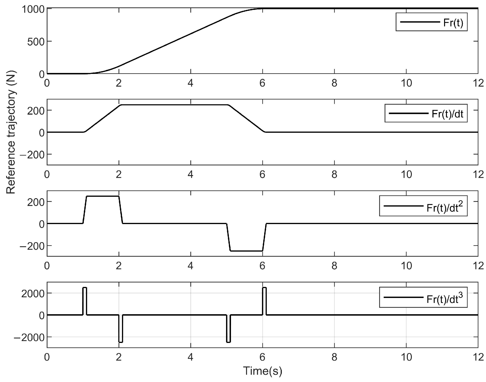
The β e used in controller is 7 × 10 8 , which is different from the model. The desired tracking trajectory is designed as implementing a linear ramp up profile, which has a third-order derivative, as shown in Figure 3.

4.2. HSEA in Contact with a Rigid Environment

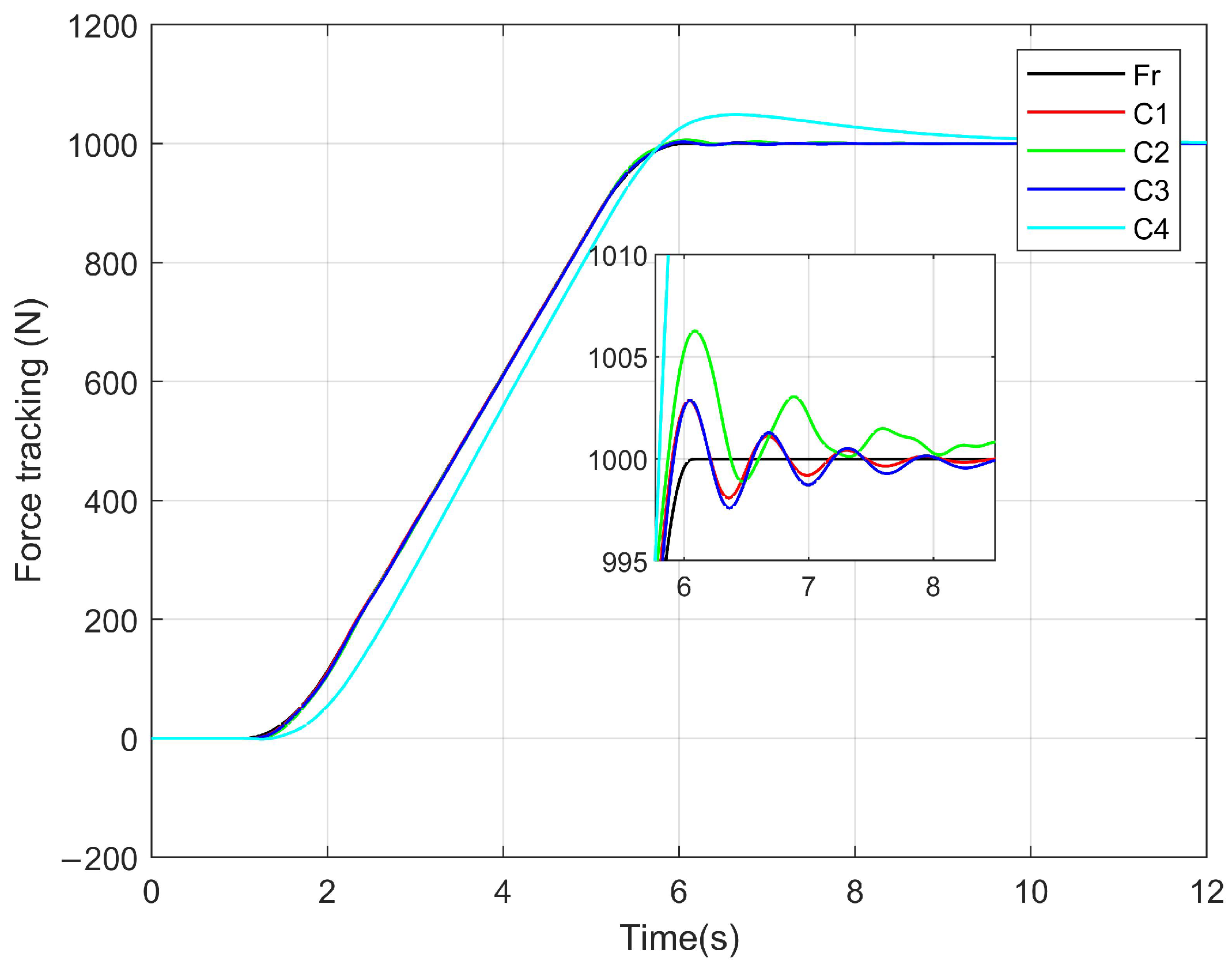
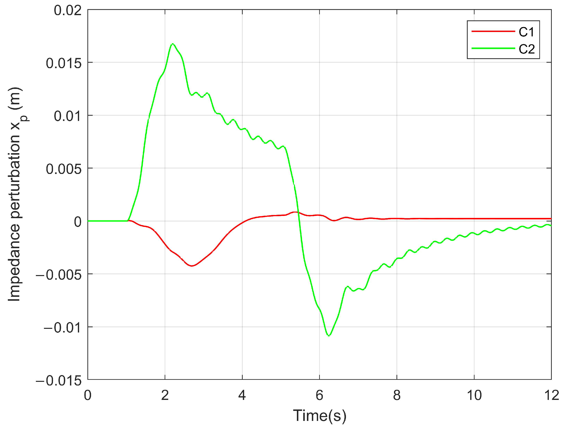
If the environment stiffness is infinite or much greater than the stiffness of the HSEAs, then K e s K s , which is often used in some work situations. The tracking performances of the controllers are shown in Figure 4 and Figure 5. Comparing the C 2 and C 1 controllers, the C 1 controller, which is equipped with the DRC position inner controller, behaves with a smaller steady-state error and faster transient performance. This is because the advanced position controller overcomes the hydraulic nonlinearity and uncertainty, which decreased the position tracking errors. Therefore, the force tracking performance is improved. Moreover, the C 4 controller shows worse performance because the force feedback information is not used by the impedance outer controller. Furthermore, the role of the impedance controller is shown in Figure 6, and x p varies drastically for the C 2 controller, which is due to the slow convergence rate. However, x p only comes into play at the turning point for the C1 controller, which is based on the perfect transient response. Therefore, the proposed method with an advanced position controller and force impedance controller can achieve precise force tracking control. The force tracking result is better compared with that in [8].

4.3. HSEA Adaptive Environment Parameter

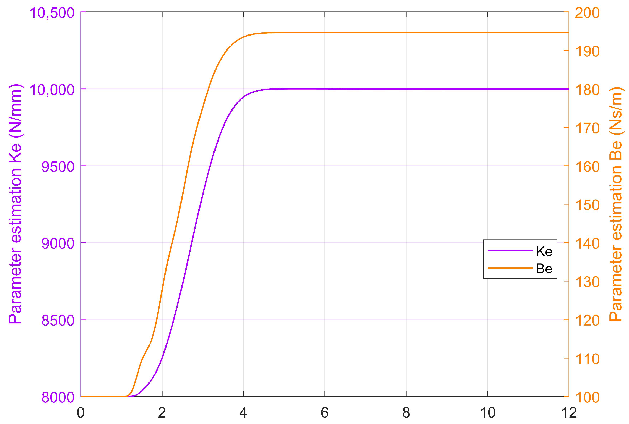
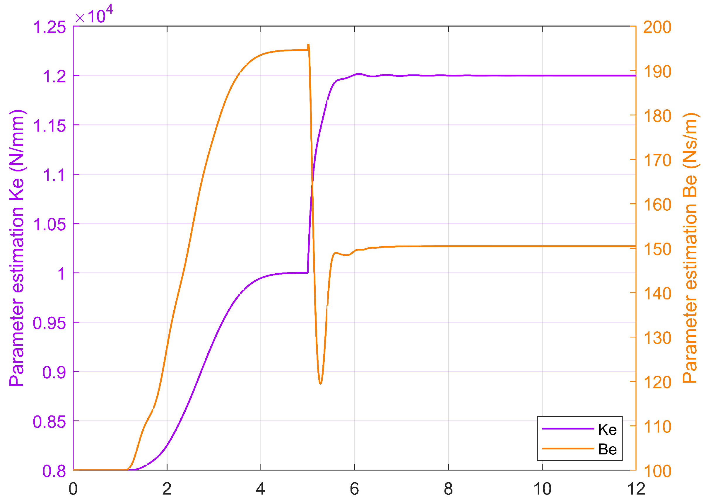
If the environmental stiffness is similar to the HSEAs and the environmental parameters are unknown, adaptive technology is an effective method to achieve force tracking control. The tracking performances based on environment parameter estimation are shown in Figure 7. The parameter estimation performance is shown in Figure 8. The C 2 controller had a larger force-tracking error than the proposed C 1 controller, especially at the outset and the stabilization phase. The stiffness of the environment and damping coefficients are estimated by the proposed adaptive technology. The adaptive gain was [ 1000 , 0 ; 0 , 66 ] . The estimation parameters satisfactorily follow the actual parameters [ 10 4 ; 200 ] .
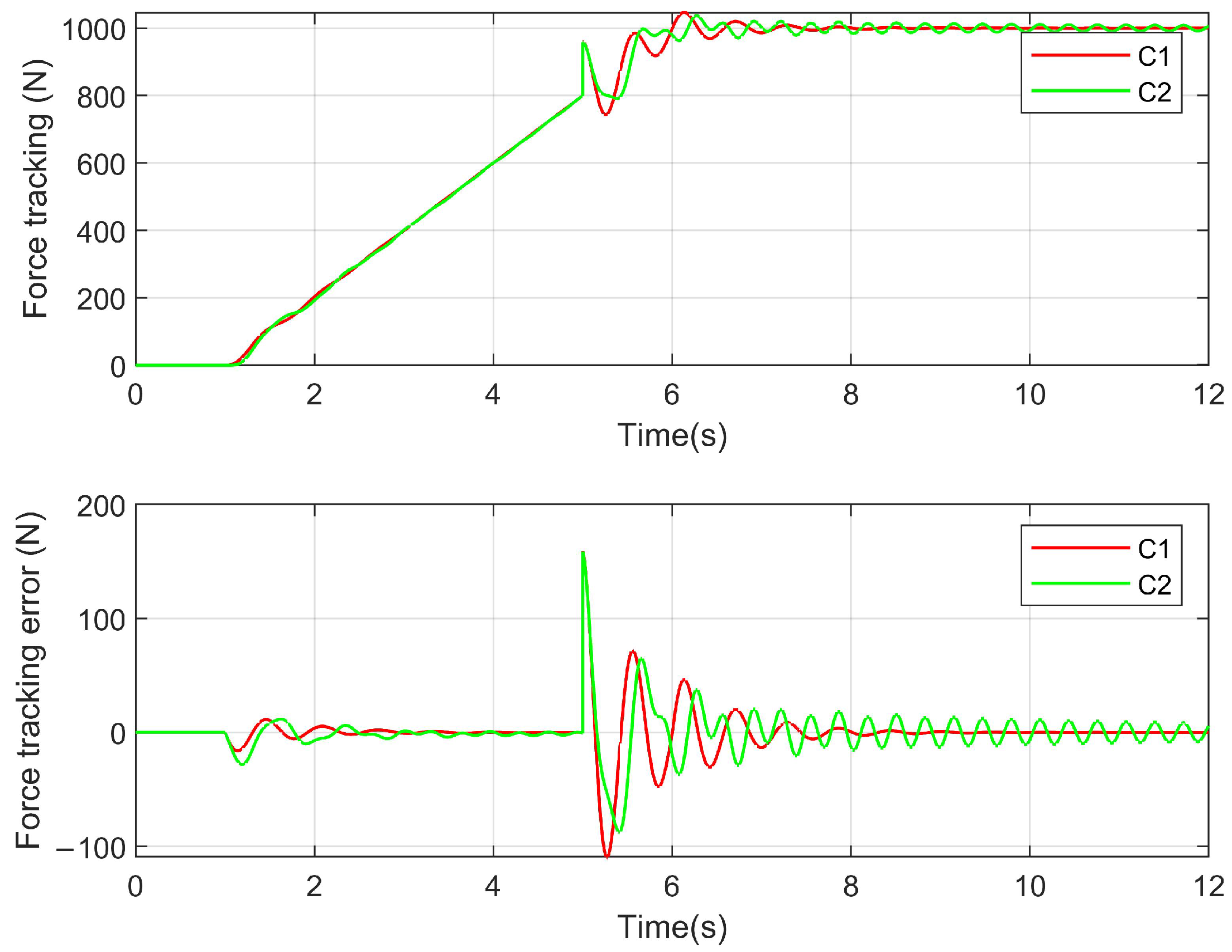
Furthermore, the variable stiffness case is analyzed as follows. The stiffness of the environment changes from 1.0 × 10 4 to 1.2 × 10 4 in 5 s. The force tracking performances are shown in Figure 9, and the estimated parameters are in Figure 10. Obviously, this parameter estimation has good validity, and the force tracking performance is also verified. The peaking phenomenon occurred because the environment stiffness suddenly changes, which shows the role of impedance control, that is, to a certain degree of compliance.

5. Conclusions

In this paper, a precise force tracking impedance control with an advanced position inner controller and an adaptive environment parameter was developed for hydraulic SEAs. In comparison with [8], the application is expanded due to the online environment parameters estimation. Furthermore, steady-state performance can be guaranteed. In addition, the force tracking precision has been improved due to the inner position control being modified by integrating the direct robust control method based on the force tracking impedance control frame. The direct robust control overcame the model uncertainty and the nonlinear and higher-order dynamic property of the hydraulic system via a backstepping procedure. The performance of the proposed method was validated using simulation. In the future, we will conduct experiments in actual systems, and the frequency characteristics will be tested. In addition, on the basis of this study [33,34,35], the energy control, coordinated/synchronized control and fault-Tolerant Control will be conducted.

Author Contributions

Investigation, Y.N. and G.L.; methodology, Y.N., J.L. (Jiajia Liu), L.L. and Z.C.; project administration, Z.C.; resources, Y.N., G.L. and J.L. (Jie Li); software, J.L. (Jiajia Liu); supervision, Z.C.; validation, J.L. (Jiajia Liu); writing—original draft, J.L. (Jiajia Liu); writing—review and editing, L.L. and J.L. (Jie Li). All authors have read and agreed to the published version of the manuscript.

Funding

This work was funded by the S&T Program of Hebei (E2021210011), the National Natural Science Foundation of China (52105065), the Hainan Special PhD Scientific Research Foundation of Sanya Yazhou Bay Science and Technology City (No. HSPHDSRF-2022-04-004), the Open Foundation of the State Key Laboratory of Fluid Power and Mechatronic Systems (GZKF-202127), and the Hainan Provincial National Natural Science Foundation of China (No. 521MS065).

Institutional Review Board Statement

Not applicable.

Informed Consent Statement

Not applicable.

Data Availability Statement

Not applicable.

Acknowledgments

We wish to thank Xiaoyan Li’s help in science writing.

Conflicts of Interest

The authors declare no conflict of interest.

References

  1. Jung, S.; Hsia, T.C. Neural network impedance force control of robot manipulator. IEEE Trans. Ind. Electron. 1998, 45, 451–461. [Google Scholar] [CrossRef]
  2. Chen, Z.; Huang, F.; Chen, W.; Zhang, J.; Sun, W.; Chen, J.; Gu, J.; Zhu, S. RBFNN-Based Adaptive Sliding Mode Control Design for Delayed Nonlinear Multilateral Telerobotic System With Cooperative Manipulation. IEEE Trans. Ind. Inform. 2020, 16, 1236–1247. [Google Scholar] [CrossRef]
  3. Yu, B.; Liu, R.; Zhu, Q.; Huang, Z.; Jin, Z.; Wang, X. High-Accuracy Force Control With Nonlinear Feedforward Compensation for a Hydraulic Drive Unit. IEEE Access 2019, 7, 101063–101072. [Google Scholar] [CrossRef]
  4. Li, X.; Zhu, Z.C.; Rui, G.C.; Cheng, D.; Shen, G.; Tang, Y. Force Loading Tracking Control of an Electro-Hydraulic Actuator Based on a Nonlinear Adaptive Fuzzy Backstepping Control Scheme. Symmetry 2018, 10, 155. [Google Scholar] [CrossRef]
  5. Jung, S.; Hsia, T.C.; Bonitz, R.G. Force Tracking Impedance Control of Robot Manipulators Under Unknown Environment. IEEE Trans. Control. Syst. Technol. 2004, 12, 474–483. [Google Scholar] [CrossRef]
  6. Alleyne, A.; Liu, R.; Wright, H. On the limitations of force tracking control for hydraulic active suspensions. In Proceedings of the American Control Conference (IEEE Cat. No.98CH36207), Philadelphia, PA, USA, 24–26 June 1998; Volume 1, pp. 43–47. [Google Scholar] [CrossRef]
  7. Seraji, H.; Colbaugh, R. Force tracking in impedance control. In Proceedings of the IEEE International Conference on Robotics and Automation. Atlanta, GA, USA, 2–6 May 1993; Volume 2, pp. 499–506. [Google Scholar] [CrossRef]
  8. Mustalahti, P.; Mattila, J. Position-Based Impedance Control Design for a Hydraulically Actuated Series Elastic Actuator. Energies 2022, 15, 2503. [Google Scholar] [CrossRef]
  9. Cao, X.; Aref, M.; Mattila, J. Design and Control of a Flexible Joint as a Hydraulic Series Elastic Actuator For Manipulation Applications. In Proceedings of the IEEE International Conference on Cybernetics and Intelligent Systems (CIS) and IEEE Conference on Robotics, Automation and Mechatronics (RAM), Bangkok, Thailand, 18–20 November 2019; pp. 553–558. [Google Scholar] [CrossRef]
  10. Paine, N.; Oh, S.; Sentis, L. Design and Control Considerations for High-Performance Series Elastic Actuators. IEEE/ASME Trans. Mechatron. 2014, 19, 1080–1091. [Google Scholar] [CrossRef] [Green Version]
  11. Calanca, A.; Muradore, R.; Fiorini, P. A Review of Algorithms for Compliant Control of Stiff and Fixed-Compliance Robots. IEEE/ASME Trans. Mechatron. 2016, 21, 613–624. [Google Scholar] [CrossRef]
  12. Shen, K.; Zhang, C.; Cheng, Y.; Wang, J.; Wei, Q.; Ma, H. Impedance control of hydraulic series elastic actuation. In Proceedings of the Chinese Automation Congress (CAC), Shanghai, China, 6–8 November 2020; pp. 2393–2398. [Google Scholar] [CrossRef]
  13. Sohail, M.; Nazir, U.; El-Zahar, E.R.; Park, C.; Jamshed, W.; Mukdasai, K.; Galal, A.M. Galerkin finite element analysis for the augmentation in thermal transport of ternary-hybrid nanoparticles by engaging non-Fourier’s law. Sci. Rep. 2022, 12, 13497. [Google Scholar] [CrossRef]
  14. Mustalahti, P.; Mattila, J. Impedance Control of Hydraulic Series Elastic Actuator with a Model-Based Control Design. In Proceedings of the IEEE/ASME International Conference on Advanced Intelligent Mechatronics (AIM), Boston, MA, USA, 6–9 July 2020; pp. 966–971. [Google Scholar] [CrossRef]
  15. Zhao, Y.; Paine, N.; Jorgensen, S.J.; Sentis, L. Impedance Control and Performance Measure of Series Elastic Actuators. IEEE Trans. Ind. Electron. 2018, 65, 2817–2827. [Google Scholar] [CrossRef]
  16. Oh, S.; Kong, K. High-Precision Robust Force Control of a Series Elastic Actuator. IEEE/ASME Trans. Mechatron. 2017, 22, 71–80. [Google Scholar] [CrossRef]
  17. Sun, H.; Chiu, G.T.-C. Nonlinear observer based force control of electro-hydraulic actuators. In Proceedings of the American Control Conference (Cat. No. 99CH36251), San Diego, CA, USA, 2–4 June 1999; pp. 764–768. [Google Scholar] [CrossRef]
  18. Liu, R.; Alleyne, A. Nonlinear force/pressure tracking of an electro-hydraulic actuator. IFAC Proc. Vol. 1999, 32, 952–957. [Google Scholar] [CrossRef]
  19. Baigzadehnoe, B.; Rahmani, Z.; Khosravi, A.; Rezaie, B. On position/force tracking control problem of cooperative robot manipulators using adaptive fuzzy backstepping approach. ISA Trans. 2017, 70, 432–446. [Google Scholar] [CrossRef] [PubMed]
  20. Wang, Z.; Zou, L.; Su, X.; Luo, G.; Li, R.; Huang, Y. Hybrid force/position control in workspace of robotic manipulator in uncertain environments based on adaptive fuzzy control. Robot. Auton. Syst. 2021, 145, 103870. [Google Scholar] [CrossRef]
  21. Helian, B.; Chen, Z.; Yao, B. Precision Motion Control of a Servomotor-Pump Direct-Drive Electrohydraulic System With a Nonlinear Pump Flow Mapping. IEEE Trans. Ind. Electron. 2020, 67, 8638–8648. [Google Scholar] [CrossRef]
  22. Helian, B.; Chen, Z.; Yao, B.; Lyu, L.; Li, C. Accurate Motion Control of a Direct-Drive Hydraulic System With an Adaptive Nonlinear Pump Flow Compensation. IEEE/ASME Trans. Mechatron. 2021, 26, 2593–2603. [Google Scholar] [CrossRef]
  23. Lyu, L.; Chen, Z.; Yao, B. Advanced Valves and Pump Coordinated Hydraulic Control Design to Simultaneously Achieve High Accuracy and High Efficiency. IEEE Trans. Control Syst. Technol. 2021, 29, 236–248. [Google Scholar] [CrossRef]
  24. Lyu, L.; Chen, Z.; Yao, B. Development of Pump and Valves Combined Hydraulic System for Both High Tracking Precision and High Energy Efficiency. IEEE Trans. Ind. Electron. 2019, 66, 7189–7198. [Google Scholar] [CrossRef]
  25. Guo, Q.; Zhang, Y.; Celler, B.G.; Su, S.W. Backstepping Control of Electro-Hydraulic System Based on Extended-State-Observer With Plant Dynamics Largely Unknown. IEEE Trans. Ind. Electron. 2016, 63, 6909–6920. [Google Scholar] [CrossRef]
  26. Nie, Y.; Liu, J.; Lao, Z.; Chen, Z. Modeling and Extended State Observer-Based Backstepping Control of Underwater Electro Hydrostatic Actuator with Pressure Compensator and External Load. Electronics 2022, 11, 1286. [Google Scholar] [CrossRef]
  27. Temporelli, R.; Boisvert, M.; Micheau, P. Control of an Electromechanical Clutch Actuator Using a Dual Sliding Mode Controller: Theory and Experimental Investigations. IEEE/ASME Trans. Mechatron. 2019, 24, 1674–1685. [Google Scholar] [CrossRef]
  28. Deng, W.; Yao, J. Asymptotic Tracking Control of Mechanical Servosystems with Mismatched Uncertainties. IEEE/ASME Trans. Mechatron. 2021, 26, 2204–2214. [Google Scholar] [CrossRef]
  29. Shen, W.; Wang, J. An integral terminal sliding mode control scheme for speed control system using a double-variable hydraulic transformer. ISA Trans. 2022, 124, 386–394. [Google Scholar] [CrossRef]
  30. Misra, S.; Okamura, A.M. Environment parameter estimation during bilateral telemanipulation. In Proceedings of the 14th Symposium on Haptic Interfaces for Virtual Environment and Teleoperator Systems, Alexandria, VA, USA, 25–26 March 2006; pp. 301–307. [Google Scholar] [CrossRef]
  31. Haddadi, A.; Hashtrudi-Zaad, K. Online contact impedance identification for robotic systems. In Proceedings of the IEEE/RSJ International Conference on Intelligent Robots and Systems, Nice, France, 22–26 September 2008; pp. 974–980. [Google Scholar] [CrossRef]
  32. Calanca, A.; Fiorini, P. Understanding Environment-Adaptive Force Control of Series Elastic Actuators. IEEE/ASME Trans. Mechatron. 2018, 23, 413–423. [Google Scholar] [CrossRef]
  33. Lin, T.; Lin, Y.; Ren, H.; Chen, H.; Li, Z.; Chen, Q. A double variable control load sensing system for electric hydraulic excavator. Energy 2021, 223, 119999. [Google Scholar] [CrossRef]
  34. Ding, R.; Cheng, M.; Jiang, L.; Hu, G. Active Fault-Tolerant Control for Electro-Hydraulic Systems With an Independent Metering Valve Against Valve Faults. IEEE Trans. Ind. Electron. 2021, 68, 7221–7232. [Google Scholar] [CrossRef]
  35. Chen, Z.; Li, C.; Yao, B.; Yuan, M.; Yang, C. Integrated Coordinated/Synchronized Contouring Control of a Dual-Linear-Motor-Driven Gantry. IEEE Trans. Ind. Electron. 2020, 67, 3944–3954. [Google Scholar] [CrossRef]
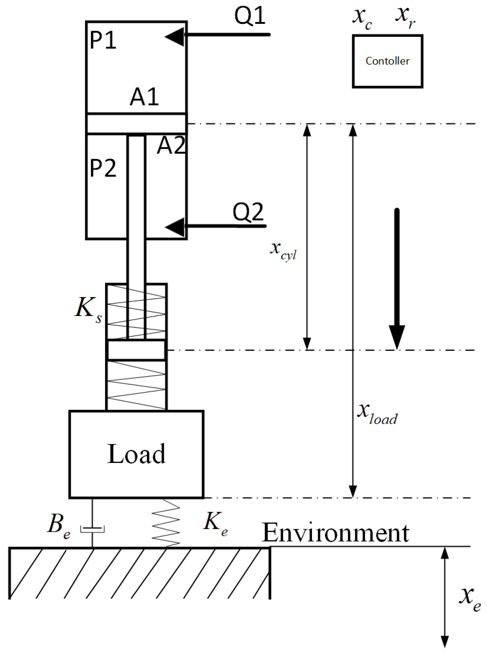
Figure 1. The structure of the single-rod electro-hydrostatic series elastic actuators. P 1 and P 2 are the pressures of both chambers for hydraulic cylinders, Q 1 and Q 2 are the flow of the two chambers, K s is the spring stiffness of SEAs, and K e and B e are the environment stiffness and damping coefficient, respectively. x c y l and x l o a d are the position of the piston and load, respectively; x r and x c are the reference and commanded position trajectories, respectively, and x e is the location of the environment.
Mathematics 10 03383 g001
Figure 2. Frame of force tracking impedance control for hydraulic SEAs. Including designed impedance model, inner position controller (DRC), and environment parameters estimation. F r is the desired contact forces, F s is the hydraulic SEA output torque, F e is the actual contact force acting on the environment, E is the force tracking error, and x P is the output of the desired impedance model based on the force tracking error.
Mathematics 10 03383 g002
Figure 3. Reference force tracking trajectory including F r , F ˙ r , F ¨ r , and F r used in controller design.
Mathematics 10 03383 g003
Figure 4. Force tracking performance in contact with the rigid environment. F r is the reference force tracking trajectory. C 1 controller behaves with a smaller steady-state error and faster transient performance compared with other controllers.
Mathematics 10 03383 g004
Figure 5. Force tracking errors in contact with the rigid environment. C 4 controller presents the largest force tracking error. C 1 controller has a fast speed of force tracking error coverage to zero.
Mathematics 10 03383 g005
Figure 6. Position perturbation. x p plays a role in the turning point to make the actuator present compliance.
Mathematics 10 03383 g006
Figure 7. Force tracking performance considering unknown and invariant environment-adaptive parameters. This picture shows that adaptive technology is an effective method to achieve force tracking control.
Mathematics 10 03383 g007
Figure 8. Environment parameter estimation performance in case of invariant stiffness. Environment parameter can be converged to actual value as the theory shows.
Mathematics 10 03383 g008
Figure 9. Force tracking performance for variable stiffness. The stiffness of the environment changes from 1.0 × 10 4 to 1.2 × 10 4 in 5 s. C 1 Controller presents faster transience and softer compliance performance.
Mathematics 10 03383 g009
Figure 10. Environment parameter estimation performance for variable stiffness. The stiffness of the environment changes from 1.0 × 10 4 to 1.2 × 10 4 in 5 s, in which the environment parameter estimation performance is verified.
Mathematics 10 03383 g010
Table 1. The model parameters.
ParameterValueParameterValue
m c y l 20 A 1 2.3758 × 10 3
m l o a d 100 A 2 1.76 × 10 3
B c y l 2000 V A 0 1.924 × 10 4
β e 7 × 10 8 V B 0 5.702 × 10 4
K s 10,000 L P 2.4 × 10 11
Publisher’s Note: MDPI stays neutral with regard to jurisdictional claims in published maps and institutional affiliations.