4. The Literature Review
The first article appears to be Webster [
20], who presents the lift force as a pressure difference. Two options are given as the source of the pressure difference; the preference is a streamline curvature and the resultant “centrifugal effect”. The other is Bernoulli, which Webster [
21] uses exclusively, where he notes “the resultant force [is] due to pressure differences”. Critically, Webster [
21] states that “if air had no viscosity, and then the wing would have no lift”; clearly, knowledge of D’Alembert’s paradox was behind early literature. Interestingly, Webster [
20] states that “the difference between empiricism and science is the existence of ‘whys’ in science”, although Webster does not address the question of ‘why’ there is an asymmetric streamline curvature unlike the symmetric streamlines predicted by D’Alembert’s paradox. Rather, he goes on to say, “In the physics of flight…we must formulate our laws in such a way that they can be used quickly and accurately…”. In this early pair of papers, we have the correct underpinning knowledge coupled with a dislike of complexity. The early images presented by Webster are very good, noting that they were used in the “1941 edition of the Civil pilot training manual” [
21].
Richardson [
22] noted that he needed demonstrations for lectures on aeronautics. While these are more generally fluid mechanics, he does present the first open test section wind tunnel. Richardson also utilizes a control line model aircraft with control surfaces to demonstrate maneuvers and control, with its own propulsion from a propeller. The controllable aircraft and wind tunnel were also combined to demonstrate the movement of the aircraft. In terms of theory, Richardson presented Lanchester [
2], which is an early circulation approach. This is shown using a Magnus effect demonstration with a rotating cylinder in front of the fan. An important demonstration presented by Richardson is Hele-Shaw flow, a type of creeping flow [
23]. Critically, Hele-Shaw flow is potential flow, and if this was an early way to visualize and show fluid flows, it is possible that this is the origin of misconceptions.
Otis [
24] presents an introduction to mathematics education for aeronautics. In his introduction, he notes that there have been previous articles; as was common at the time, these deal with general education, especially with the need for aviators in the war effort. As such, Otis is the first technical mathematical education article. Bernoulli is effectively presented as a case study, given that an entire outline is presented for all mathematics and science in aeronautics. Unlike the realistic flow illustrated by Webster before, we see the first example of ‘flat bottom flow’ (like
Figure 11). While Bernoulli is well presented, the causal link comes from the path length difference and a statement of equal transit time. The only reference is to Otis’s own book, given as the source for the images [
25]. This early book likely represents a significant source of misinformation.
Practical education aspects, such as demonstrations and laboratories, occur very early in the education literature. This is not a surprise, given that there was a long tradition of experimentalism in fluid mechanics due to the difficulties in developing theories that provided predictive power, etc. Blanchard [
26] discusses a number of aviation-relevant experiments, including radio and instrumentation. Of more relevance is the venturi tube with u-tube manometer measurements. This is followed very quickly with another open wind tunnel using a fan [
27]. Bates [
28] presents a slightly improved design, which gave better results. Later, Katz [
29] presented an airfoil device similar to these, intended to show the difference between lift on a flat plate and a curved airfoil; the associated theory is that of Bernoulli, where the shape of the airfoil is responsible for the observed differences. Overstreet [
30] also presented an open wind tunnel as their student project and once again utilized Bernoulli in terms of pressure difference to explain lift.
The October 1954 edition of the National Science Teachers Association’s (NSTA) Elementary School Science Bulletin was entitled “Ideas for Aviation Science” [
31]. The content starts with the general concept of pressure. This immediately becomes problematic, as they claim that air from a fan has reduced static pressure, which is incorrect. The fan adds kinetic energy to the fluid, above the static pressure, giving it a higher total pressure. This information may represent a fundamental source of this misinformation, which is likely well entrenched. Also presented is the demonstration of blowing between two apples and the cotton spool card levitation trick, both as explained as pure Bernoulli demonstrations; however, the Coanda effects need to be considered. Finally, they also present the same flat-bottom flow visualization used in Otis. The underlying principle discussed is Bernoulli, with the shape described as being responsible for faster flow above relative to below and hence a lower pressure above relative to below.
The next work is by Wild [
32]. It is apparent that Wild was an engineer as opposed to Webster, who was a physicist. Wild, as most engineers do, states that in air, viscosity is negligible but critically notes Prandtl’s boundary layer, which contains the viscous effects. This is a common point from engineers: “(1) we can ignore viscosity, (2) all viscous effects are in the boundary layer”. At a basic level, this is true—viscosity is negligible outside the boundary layer—but without it, there is no boundary layer; that is, if there is a boundary layer, then viscosity cannot be ignored. Wild starts as most aerodynamic approaches do, with potential flow around a cylinder, and importantly notes that Bernoulli can be applied to relate the pressure and velocity, a correct statement when viscous effects are negligible. Following this, the Kutta condition is presented, with the sharp leading edge of an airfoil being the mechanism as to ‘why’ there is circulation. This is a common point of confusion by engineers, the notion that D’Alembert’s paradox is resolved by the Kutta condition and the need for a sharp trailing edge, when it is, in fact, resolved by including viscosity.
Heck [
33] presents similar manometer flow experiments to Blanchard, giving the first straw-to-straw venturi activity. Heck also presents a “hump” as an analog to a wing, in a half venturi tube to emulate how a wing produces lift, with a reduction in pressure over the top surface; while related, this is too much of a simplification. The underlying knowledge is Bernoulli, where the shape of the airfoil is what is needed to produce the difference in pressure resulting in lift. Similar examples are provided by Fiorello [
34], who presents a “flying machine” for education purposes. The knowledge here mirrors almost everything in the NSTA’s 1954 bulletin. That is, Bernoulli coupled with the shape results in the lift force. Interestingly, there is correspondence from De Waard [
35], but the criticism is only about which of Newton’s laws is applicable to thrust.
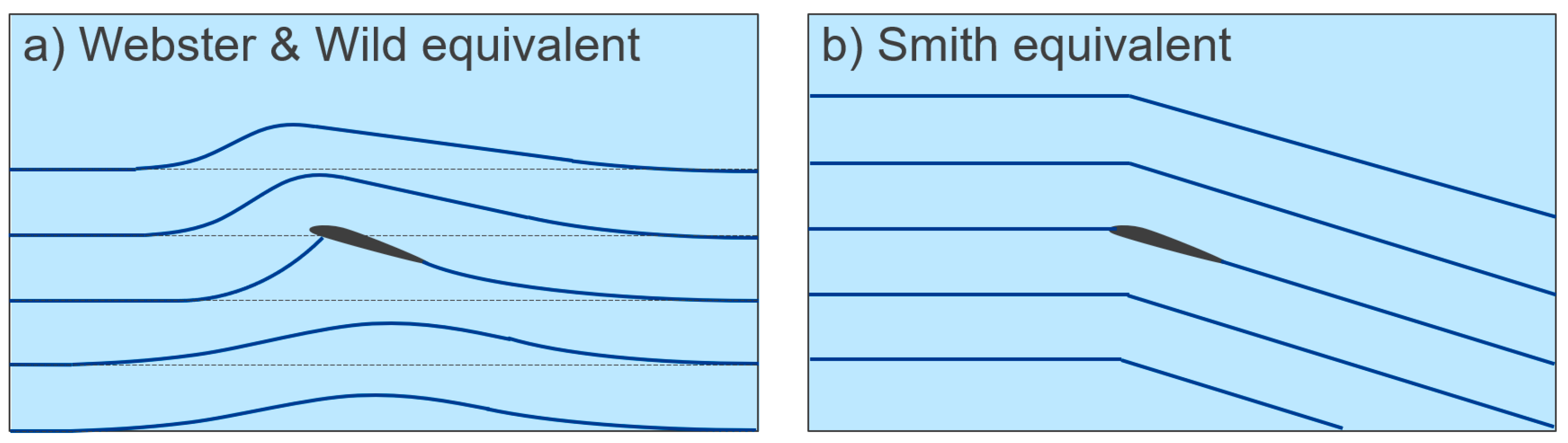
Smith [
36] rightly states that Bernoulli’s “theorem was never postulated to deal with dynamic lift but is only an expression for the law of conservation of energy inside an isentropic stream-tube of fluid”. That is, any statement to the effect that “lift is explained by Bernoulli alone” is incorrect. As mentioned before, outside the boundary layer, in inviscid flow, Bernoulli correctly relates the static pressure and velocity along a streamline; as such, if you know one, you can determine the other. In fact, this is what is taught to aero students in that second course on aerodynamics; they use potential flow and circulation to calculate the velocity vector field, and then they literally use Bernoulli to calculate the corresponding static pressure at every point in the field [
37]. Smith notes issues in science education in the USA; he is critical of the general dependence on Bernoulli, which we have noted is in almost every proceeding article to date. Smith also notes equal transit time as being standard in textbooks in the USA; he goes on to say, “We can quote no physical law that tells us this”, although equal transit time is a result of D’Alembert’s paradox [
8]. Smith correctly attributes the lifting force to a pressure difference; however, he goes on to be the first to use an incomplete Newton’s 3rd Law argument. Crucially, if you compare the images in Wild [
32] and Webster [
21] to those of Smith, you can understand why he made a poor inductive leap to this conclusion (see
Figure 13); Smith’s illustrations of air flow around an airfoil are fundamentally wrong and are repeated numerous times in future articles. Interestingly, Smith notes a critical and insurmountable issue with Newton’s 3rd Law explanation, saying, “We cannot easily set up an experiment or a calculation of dynamic lift to prove this principle”. Rather, Smith relies on the analog of a helicopter (a rotor wing) or a propeller, which work by momentum transfer as noted in
Section 3.2.2. He further softens his position by saying, “although the wing is much simpler than the propeller, we cannot easily set up an experiment (or a calculation) to illustrate or prove the momentum principle…”. What makes this odd is that Smith was a NASA engineer, who should have been aware of the circulation method to correct potential flow and estimate lift at small angles of attack. Smith published similar work the following year [
38,
39].
Fletcher [
40] cites previous work, with a classical text [
41], and a modern classic [
42]. Fletcher does not give any specifics. He states that his physics curriculum includes a discussion of Bernoulli and the force and momentum discussion for propellers to produce thrust; the how and why of wings are not discussed in the article. Fletcher follows this with an extended version [
43]. Fletcher also derives a sin law analogous to Newton’s sine-squared law (discussed in the Summary section below), which is controversial (and results from the incorrect flow in
Figure 13b). Fletcher correctly uses the important coefficients of lift and drag, as necessitated when referring to a text like Kermode [
42]. However, he uses an incomplete Newton’s 3rd Law statement to explain their origin.
While Barnes and Potter [
44] discuss the aerodynamics in sporting applications, they present the first account that captures the key aspects of Prandtl. The only issue in their work is a lack of Navier–Stokes; however, this is trivial since they clearly use viscosity confined to the boundary layer as the source of the flow asymmetry resulting in lift.
The great debate around the use of Bernoulli starts with Bedford and Lindsay [
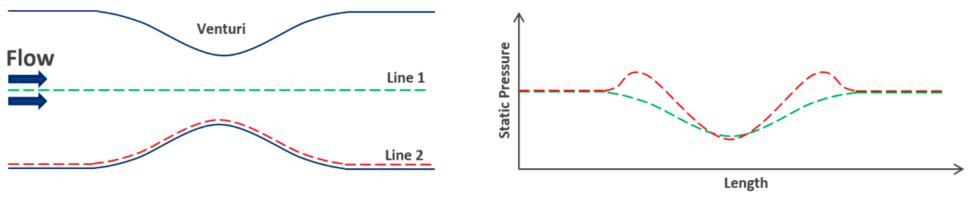
45], though not directly about lift. May [
46] presents a simple activity based on toy gliders, and Bernoulli based on the shape of the wing is given as the mechanism for lift. Consuegra [
47] presents a similar activity but using paper airplanes, although no theory is presented for flight mechanics. Another preliminary paper is Martin [
48], which has follow-up correspondence [
49,
50]. Martin presents a paradox in Bernoulli, which is often overlooked. When most consider a venturi tube, the flow speed is shown higher at the narrow section. This is acceleration, which needs an associated force that is not covered by Bernoulli. However, to force the air faster into the narrow section, there is an increase in pressure on the wall during the constriction. Most only plot the pressure and velocity along the middle of a venturi and ignore what happens at the surface; both are included in
Figure 14. Barnes [
51] critically misinterprets Bernoulli, noting that it dictates that if fluid flows past a surface, then the pressure will just be lower. While this is true if the Coanda effect is included, there is nothing inherent in Bernoulli that suggests this. Barnes presents many of the fundamental educational activities such as blowing across curved paper, the cotton spool, etc. The underlying principle in terms of lift is Bernoulli and the shape of the airfoil. Brusca [
52] appears to cause the biggest impact on the Bernoulli debate, which is not surprising because he incorrectly uses Bernoulli to explain the Magnus effect for a rotating ball and a Flettner rotor; he also uses an exclusively Bernoulli explanation for a stream of air lifting a piece of paper and levitating a ball. There is a letter and response from Murphy and Brusca [
53], although this does not add much. There is another letter and response from McCaughan and Brusca [
54]. Kesling [
55] presents similar activities, also noting the misconception that “faster air has lower pressure”. These articles, especially the correspondence, highlight that these demonstrations, such as the levitating ball, should be avoided when discussing lift. While they involve aerodynamics, moving air creating forces, they do not directly relate to wings.
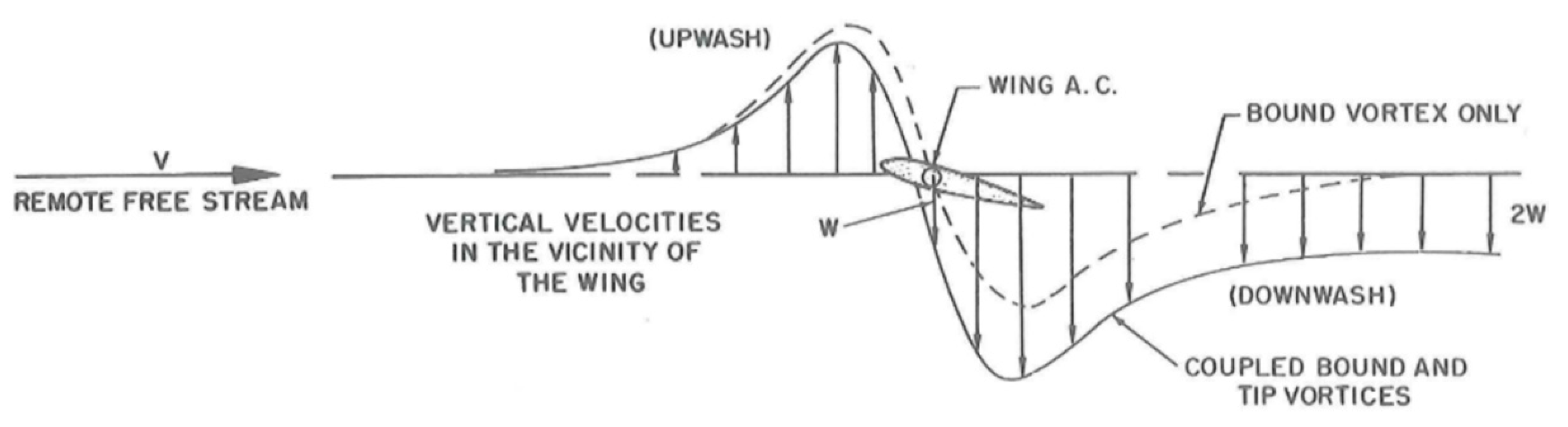
Wegener [
56] presents similar material to Wild [
32] and Barnes and Potter [
44]. He discusses the boundary layer containing the viscous effects. Of note is the insight he gives to potential flow solutions, from which we may infer how aviators have incorrectly applied Bernoulli. Wegener notes that the solution to Laplace’s equation gives the velocity potential and the stream function. Knowing the velocity field, the application of Bernoulli gives the resultant pressure, although this is for inviscid flows that do not produce lift. Still, it highlights that many want a heuristic shortcut to remove the complex and incomplete mathematics of potential flow such that if they had a velocity difference (circulation), it could then be used to give the pressure via Bernoulli, which is the source of lift. Another key feature of Wegener is that it is the first 3D flow visualization presented in the educational literature. While Wild [
32] mentions wingtip vortices and downwash, Wegener gives a thorough description, which importantly does not include statements about this being the source of a momentum transfer and hence a Newton’s 3rd Law explanation for lift, which is a growing common misconception.
Figure 15 illustrates the issue, which shows that for 2D flow (bound vortex only), there is no acceleration to the flow such that it has a sustained velocity; this only occurs in 3D flow (coupled bound and tip vortices). This is discussed further by Wild [
57].
Flynn [
59] and a correspondence by Monce [
60] do not discuss the principle of lift, only other aspects of flight mechanics. The mistake of Flynn as pointed out by Monce is that the angle of attack of an aircraft does not equal its climb angle. In general, this is another common confusion students have: “if the nose of an aircraft is pointing up, it must be flying up”. As correctly illustrated by Monce, before an aircraft touches down, it has its highest angle of attack, and it is landing, not climbing.
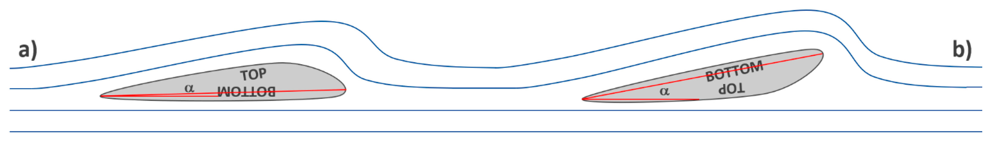
While Weltner [
61] correctly attributes lift to a pressure difference, he incorrectly asserts that Bernoulli is the underlying principle. He goes on to use an inverted-flight argument to disprove equal transit time. He includes another incorrect argument against equal transit time; this relates to the fact that at some angles of attack for some airfoils, the pressure may be above ambient across the lower surface. While this will mean the flow velocity underneath will always be below the freestream velocity, it does not directly preclude equal transit time. Weltner then references Smith and goes on to utilize a Newton’s 3rd Law explanation. The mechanics of propellers and rotors are used as the basis for this. Looking at the images presented by Weltner, you can see the logical approach taken and the reason for this erroneous conclusion (see
Figure 13b). A jet of air close to an airfoil is used to blow it as if it were a sail tacking across the wind, and Weltner equates this to a literal jet on the boat such that it produces the same force components. This is not freestream, and, hence, it does not produce the required upwash. It is effectively the first visual representation of what will become the modern Coanda explanation. This is compounded with a sin law argument. Weltner highlights another important point of confusion, where the flow at the trailing edge is equated to the flow in the rear far field, which is not the case. One further point, as with Webster, is that the streamline curvature is also presented. The final twist to Weltner is that he references Prandtl as evidence to support a Newton’s 3rd Law statement, which was provided at the end of
Section 2. Clearly, Prandtl is not implying that a simple statement of Newton’s 3rd Law alone is applicable, as Weltner claims.
Weltner [
61] is also the start of the second great debate on Bernoulli in the literature. Auerbach’s [
62] correspondence to Weltner immediately and correctly defeats the inverted flight argument, although this has not prevented it from being used by others. While Auerbach defends Bernoulli hard, it is not clear if he is insisting that Bernoulli alone is responsible for lift, which would be incorrect. Importantly, he does give the context of an elliptic partial differential equation, and the issue with ascribing cause and effect in such a context. Auerbach concludes with a statement that deflection (Newton’s 3rd Law), as presented by Weltner, is “important” and appears to represent a misunderstanding of circulation. This is the first case of ‘circulation plus downwash gives lift’. Weltner [
63] responds with a statement that ‘streamline curvature plus Bernoulli explains lift’. While not correspondence, Huebner and Jagannathan [
64] immediately follow Weltner, who is cited. They also cite Smith’s Newton’s 3rd Law explanation and incorrectly state that Bernoulli is technically not applicable because it “violate[s] the conditions assumed in deriving [it]”. Indirectly, Badeer and Synolakis [
65] add to the discussion, noting that Bernoulli is often incorrectly applied, supported by both Smith and Weltner. Weltner [
66] is a clear continuation of his previous work [
61]; in 1987, he proposed experiments to validate what he was saying, and in 1990, there are photos of real experiments. Importantly, none of the conclusions in his earlier work were wrong in their context; they were just not applicable to freestream flow around an airfoil. Hence, it is no surprise that these experiments affirm Weltner’s position; they just do not demonstrate how a wing works. To give an example, in air ducts around corners, vanes are commonly used to reduce losses, the concept that a vane will more efficiently turn air through 90 degrees is true, and at the corner, there is also a reaction force as the flow accelerates (changes direction); however, none of that is directly related to how a wing produces lift. This is the same as sticking a vane on top of a frictionless cart and blowing a jet of air at it; it produces motion, but that is not how a wing works. Weltner again cites Prandtl as a source for lift being explained by Newton’s 3rd Law, which is not the case. Unnecessarily, Weltner [
67] continues with a second article in the same publication, repeating the other aspects of his 1987 work not covered in the previous pages. In correspondence to Weltner, Freier [
68] repeats Wild (1966) that circulation is the correct explanation. Interestingly, the circulation argument by Freier is used to explain both a pressure difference (Bernoulli explanation) and a downward momentum in the flow (Newton’s 3rd Law explanation). Freier also appears to be the first to state that you cannot apply Bernoulli across streamlines and hence that Bernoulli cannot be used to compare the upper and lower streamlines. In fact, you can if the total pressure in the two streamlines started at the same value and you apply conservation of energy, which is true outside the boundary layer; you can simply track each streamline independently. In his response to Freier, Weltner [
69] clearly articulates the key criticism of just using circulation; that is, circulation is an effect, not a cause (the underlying cause is viscosity).
Bauman and Schwaneberg [
70] link the first debate (Brusca and others) and this second debate (Weltner and others) about the relevance of Bernoulli. There are essentially no new points added. The fact that Bernoulli is derived from Newton and hence applicable is well stressed. Bernoulli is invoked again as the only reason for a curved piece of paper to lift when blown across (and to explain the curvature of a spinning ball); that is, there is no reference to Coanda or Magnus, which are needed. They do correctly defeat the inverted argument, noting that the angle of attack is typically omitted (see
Figure 11). They assume that helicopters are simply wings “moving”; Smith (1972) previously noted the difficulty in this reasoning. On the topic of circulation, they say, “The mathematical fiction has apparently led to the common statement that one cannot explain lift in terms of irrotational flow”, which is not fiction; it is literally D’Alembert’s paradox. Oddly, they conclude their section on lift by stating that downwash from wingtip vortices adds to lift, when these reduce lift [
14]. Weltner and Ingelman-Sundberg [
71] follow up on Bauman and Schwaneberg [
70], repeating much of Weltner’s prior points, although the new and revolutionary notion of Coanda is utilized following Raskin [
72]. Similarly, at the same time, Weltner and Ingelman-Sundberg [
73] presented further similar work. It should be noted that there are more modern versions of these 1999 articles online, and they first appear in the literature cited by Eastwell [
74].
Fields [
75] gives a wonderfully soft introduction. Importantly, while demonstrations of the lifting paper are used, no names are referred to, and, hence, no confusion is presented; this is probably the ideal solution—to present the concept that moving air can move objects, with no exclusive statements about pressure or momentum, and no names. As such, there can be no confusion. The approach to middle school aerodynamics should be a simple clear empirical science endeavor. Pols, et al. [
76] also present aeronautics for middle schoolers; however, a radically different approach is taken. Interestingly, these mechanical engineers use an equal-transit-time-related explanation (path length difference). They also utilize levitating paper and ping pong ball demonstrations explained by Bernoulli with no Coanda. Importantly, they do present the first classroom wind tunnel with an enclosed test section. Holmes [
77] also presents the blowing across a straw demonstration used by Pols, Rogers and Miaoulis [
76], and first used by Heck [
33]. Telfer [
78] presents some middle school mathematics based on flight, using both Bernoulli and the shape of a wing to explain lift, along with a statement of Newton’s 3rd Law. Macalalag, et al. [
79] used paper butterflies to talk about lift, and while this is admirable, the aerodynamics of very small flapping wing animals is radically different from the fan blowing against paper analogous to flying a kite. Hoover [
80] presents flight with Bernoulli, using many of the previous aerodynamics activities as presented by the NSTA in the 1950s, which are likely very common demonstrations nowadays. The issue with Hoover in contrast to Fields is that the use of a label means you need to be correct, or you are presenting misinformation. The original hanging apple demonstration was replaced by a pair of empty soda cans standing on a bed of drinking straw rollers by Hewitt [
81]. Hoover’s version of this has the soda cans laying on their side, which potentially eliminates the Newton’s 3rd Law aspect of the Coanda argument; he then goes on to blow between two hanging balloons, which reintroduces the problem. In general, the demonstrations presented are great examples of fluid mechanics and aerodynamics; however, they are not relevant to flight mechanics.
Sprigings and Koehler [
82] present a sports science introduction to dynamic lift, although a better one was presented previously by Barnes and Potter [
44]. Given that Koehler is a physicist, much of the material above regarding Bernoulli verses Newton is covered. However, from “simple assumptions”, they derive Newton’s sine-squared law, which Newton himself knew was wrong. This is hand-waved away by claiming the small angle approximation and then simply presenting the correct lift equation. The curvature of a spinning ball is used as evidence to support the conclusions, noting that one of the simplifying assumptions was that the speed of the flow around the body does not change, which is needed for the Magnus effect to give an additional force on a spinning ball [
12].
Gerhab and Eastlake [
83] do not directly contribute to the how or why of lift; however, their presentation of projects around boundary layer control is a good description of boundary layers and their importance. This is beneficial to the lift education literature and is cited more than once by future authors.
Raskin [
72] is a pivotal paper and not for a good reason. This marks the first presentation of Coanda. While Coanda was described in
Section 2.1.3, in the literature, Coanda becomes the
deus ex machina for lift education. That is, it explains the unexplainable, as the concept is used well beyond the actual definition of the effect to encompass the continuum hypothesis and all viscous effects. It even gives the streamline curvature providing a direct Newton’s 3rd Law explanation for lift. Raskin combines this idea with Smith before him, and the legitimacy given by many intervening authors, giving the modern Coanda paradigm. Importantly, around an airfoil, there is no jet of fluid entraining the surrounding fluid. In fact, a goal in aerodynamics is to achieve laminar flow over an airfoil, which would preclude entrainment, and the flow initially starts laminar, where there can be no entrainment. As such, Coanda is not involved in aerodynamic lift.
Tamarkin and Bourne [
84] use paper airplanes for very young students. This is a great endeavor, although the oversimplified statement that the force of air under a wing pushes it upwards is an issue (ski effect). Baird, et al. [
85] present another paper airplane approach, using the equal transit time theory to explain lift. Greene [
86] also presents many of the same aerodynamics activities by blowing across paper, etc., and using paper airplanes. Here, Bernoulli is not used, but only an explanation based on pressure difference. Chiles [
87] demonstrates a similar approach to Fields, also utilizing paper airplanes for year six students. It is clear that Chiles has a larger syllabus, but no details are provided to conclude if names like Bernoulli or Newton are used. Oliver and Ng [
88] present a slightly different approach to the paper airplanes, using a rubber-band-powered toy aircraft contest for primary and secondary students. Waltham [
89], building on from previous work [
90], presented an advanced way to utilize a model glider, like those proposed for primary and secondary education prior. The experimental approach is ideal as intended, and the only issue is the explanation and details of lift. The simple explanation is a statement of Newton’s 3rd Law, where wings “deflect air downwards”. Schneidermeyer [
91] also presents a simple aerodynamic activity, this time with flying discs; the underlying theory presented is Bernoulli, with the explanation based on the shape of the disc. Sterling [
92] also appears to be addressing education at lower levels. In this, she simply uses a pressure difference explanation for how, and no names appear to be used to “label” the effects. McGrath [
93] presents the use of paper airplanes, along with some demonstrations around pressure, a key feature of lift, although the curved shape of the wing is used as the explanation for lift. Bun [
94] also uses a rubber-band-powered model aircraft, similar to Oliver and Ng. Mason, et al. [
95] utilize polystyrene foam to make model gliders, and the underlying science of lift is provided by NASA based on a path length difference and Bernoulli. Bautista [
96] utilized paper airplanes to talk about lift but with no theory. Katchmark, et al. [
97] present the use of paper airplanes while not using Bernoulli; lift is explained as a pressure difference. In general, there is a very large body of literature on paper airplanes. These have many educational applications, far from just the mechanics of flight. Most tend to focus on science and mathematics, but there are many others. Likely, only a fraction of those that use paper airplanes as a tool to teach about lift have been captured. However, the sample here appears homogenous in approach, and the topics discussed tend to focus on early simple theories, coupled with fallacious reasoning.
Beaty [
98] represents the modern view of all Bernoulli arguments. That is, it is inherently wrong because it is associated with a curved upper surface, longer path lengths, or equal transit time. This is simply not true and is the default argument used by those who want to dismiss the pressure difference as the source of lift. This is clear from Beaty’s conclusion, which is that Newton’s 3rd Law is more intuitive and thus should be used at elementary levels. Again, if Bernoulli is used on its own, it has no hope of explaining lift, and all of these incorrect crutches have been used in education contexts; however, looking at the fact that there is a pressure difference and that it is used to determine the coefficient of lift, you are supposed to be compelled via the scientific method to find a reason for that.
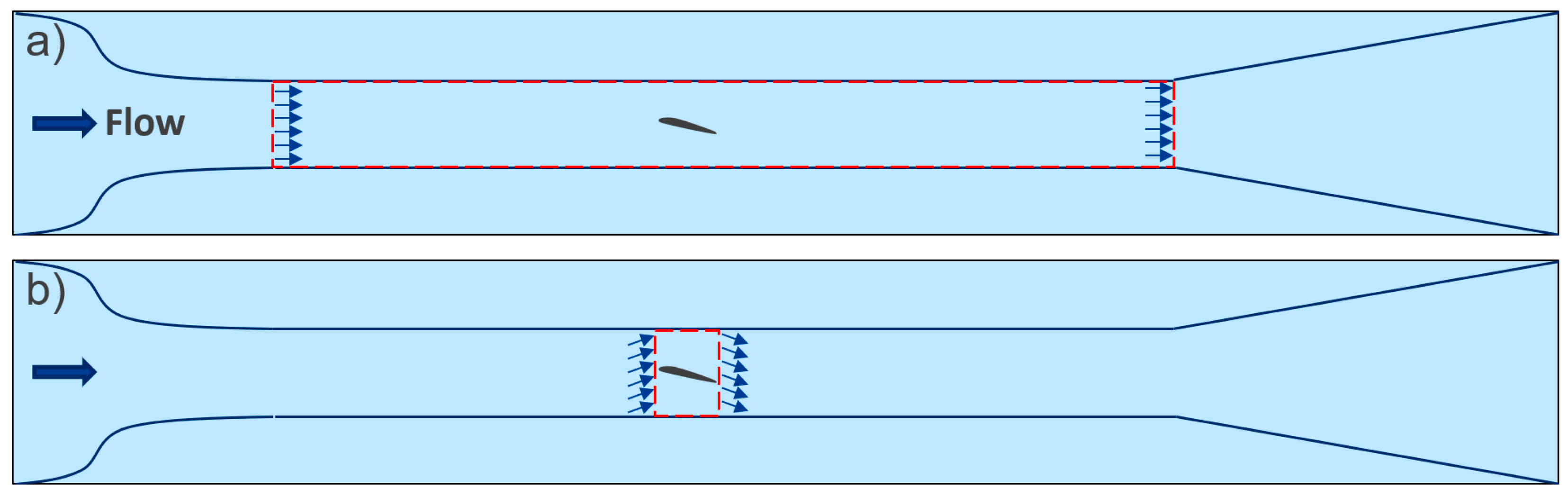
Lissaman [
99], like Barnes and Potter [
44] and Wegener [
56] before him, is another tour de force. Sadly, Lissaman has only a single citation recently from McLean [
18]. Lissaman simply and elegantly explains what we know because of Prandtl and his contemporaries. It is a shame this engineering article made no impact on the science education community because Lissaman was a clear authority, a statement easy to make in hindsight, though the reason for this is clear in the heavy use of calculus. The previous derivation and quote from Prandtl [
3] demonstrated that for a circular control volume, the momentum and pressure terms each contribute half the lift. Lissaman shows the same result for a square control volume around an airfoil and concludes that for the case of
Figure 7a (long horizontal control volume), the pressure term will dominate, and if an equivalent long vertical slice can be produced, the momentum term will dominate. Importantly, pressure and momentum do not exist without each other. Lissaman combines circulation, Bernoulli, and Newton.
Waltham [
100], like Fletcher [
40], derives another sin law equation. As with Fletcher and Sprigings and Koehler [
82], the incorrect application of Newton’s 3rd Law is at play here, along with another version of
Figure 13b illustrating the “intuitive” air flow.
Anderson and Eberhardt [
101] incorrectly state that Bernoulli requires equal transit. It is possible to have a Bernoulli argument and not require equal transit [
32]. Similarly, they link this “popular explanation” (Bernoulli) to wing shape, which, again, in the proceeding literature is not always the case. Anderson and Eberhardt go on to state that because of the link to wing shape, Bernoulli cannot explain lift at different angles of attack, a statement made on the premise that changing the angle of attack somehow does not constitute a change in geometry. The underlying misconception here is that the flow splits at the leading edge, which is not true. Critically, they present what is called the “physical description”, which they state has “no design or simulation capabilities”, which, for a physical law, is very problematic. Further, they criticize the Bernoulli-based explanation with the inverted flight argument, which was covered in
Section 3.2.1. and dismissed previously in the literature. While presenting weak points, they also clearly articulate the correct issue with Bernoulli, noting that it is applicable, but it is not self-consistent enough to give the velocity changes to enable the correct pressure calculation. Anderson and Eberhardt [
101] also present an elegant statement of Newton’s 1st Law, which has been absent in the literature until now; this links Newton to streamline curvature nicely. While they correctly use viscosity, they conflate this with Coanda. To make matters worse, to show the Coanda effect, they use a spoon with water and not air, which is actually a demonstration of surface tension [
18]. They present the “wing as a scoop”, which looks very similar to the sin and sine-squared law images incorrectly presented above (
Figure 13b). One of the key points to take away from Anderson and Eberhardt [
101] is their criticism of lift from airfoils in 2D, claiming that it is not a real-world effect. Consider the question, does an airfoil work on the passing air? If we use potential flow, the answer to this is no. This is an issue if the Kutta condition and circulation are included as quasi-viscous effects such that the result is lift and no drag. In both cases, the compression and expansion (either symmetric for the pure potential flow or asymmetric for the circulating flow) are isentropic. However, if viscosity is included as the actual mechanism for asymmetry and hence lift production, then there cannot be adiabatic and reversible processes, as viscosity gives a loss of energy due to friction. The criticism and even dismissal of airfoil lift is compounded by the conflation of lift with downwash and wingtip vortices (see
Figure 16); it is well known that these vortices constitute a reduction in lift, and the energy needed to produce them is a source of drag [
14,
102]. Their final point is around the ground effect and how the observed increase in lift comes about due to a reduction in upwash; however, this is actually because of a reduction in downwash, which reduces the effective angle of attack and induced drag [
103]. Kunzig [
104] presents the work of Anderson & Eberhardt in Discover magazine, repeating their key points and noting they are easier for a third grader. While their first article was in Sport Aviation, the work of Anderson and Eberhardt [
105] is similar, just as a preprint on the Fermilab server, submitted to the American Journal of Physics but never published. In this second work, the authors have softened the extreme links between Bernoulli and fallacious arguments. They attempt to validate their preferred Newtonian explanation by claiming that it predates Bernoulli in education texts; as noted above, this is not the case. Webster was using Bernoulli in 1920 and was responsible for the official training syllabus during the exact time period mentioned by Anderson & Eberhardt. The study by Anderson and Eberhardt [
106] appears to be unpublished work that directs readers to their book and ultimately repeats the previous points. The preprint article by Ceil [
107] presents the information from Anderson & Eberhardt. Similarly, the lift for biological science from Ingle, et al. [
108] also repeats the ideas of Anderson & Eberhardt.
Auerbach [
109] highlights the relationship between the need to use the pressure difference and momentum flux together. Like
Figure 7, different-shaped control volumes are presented. The point of clarity is that one can consider the atmosphere that contains an aircraft flying, where an infinite horizontal distance is possible (the curved geometry of the earth facilitates this) and, hence, a pure pressure lift is possible. However, since the wing is finite, using a bounding vertical rectangle, which cannot be infinitely high (there is the earth surface and the top of the atmosphere), it means that a pure momentum flux case cannot be constructed.
Hoffren [
110] adds more to the discussion. As with other aeroengineers, there are good points that mirror the central discipline. He highlights the vortex-based explanation used to justify circulation, with names such as Helmholz, Thomson, and Kelvin [
7]. Importantly, Hoffren answers the question about why there are those that think the upper and lower surfaces have exact fractional contributions, which is not the case with a PDE solution. This is based on a “faulty interpretation” of Eiffel and the 2/3-1/3 rule. While Eiffel had a rule, it is incorrectly extrapolated to mean that 2/3 of the lift is due to suction on the top surface and 1/3 is due to higher pressure on the bottom surface, which is not the case. Interestingly, Hoffren does not agree that viscosity is the underlying mechanism, although he gives seven references in support of viscosity, and one against, and then states “…there is no rigorous proof for the claim [against viscosity], and that the discussion is mostly of academic interest…”. Hoffren is also perplexed by the singular perturbation problem (the boundary layer represented mathematically), stating that “This kind of behavior in any physical phenomena is extremely rare, if known at all”. The general description presented by Hoffren is very good, and this is the first instance where an image correctly illustrates the collinear nature of the streamlines in the far field (see
Figure 13a), supported by an explanation. However, Hoffren goes through the effort of establishing the correct flow field only to fall back on a Newton’s 3rd Law statement, based on the downward turning of the streamline after the airfoil.
Eastlake [
111] makes a plea that is worth repeating, if you focus on one aspect, the pressure difference or momentum flux, you should not preclude the other because there will be issues. As previously mentioned, this is more problematic when precluding pressure because a control volume can be constructed that facilitates a purely pressure explanation, but the same is not true for momentum (see
Figure 7). Furthermore, Eastlake gives “Newton” as an explanation, which should actually be Navier–Stokes, the correct application of Newton’s Laws of Motion for fluids. Eastlake correctly states that the confusion with inverted flight arguments is due to the lack of stagnation points showing where the flow divides and hence where the “upper” and “lower” surfaces are aerodynamically rather than geometrically (see
Figure 17). Unfortunately, Eastlake does state that it would be possible to measure the vertical velocity of the flow and determine the lift from it. Since a control volume cannot be constructed that purely uses momentum, this is not actually possible.
There are also educational articles that utilize rotor wing demonstrations. The first of these uses a simple party favor style toy with a balloon used as a reservoir of pressurized air to start a set of three rotor blades spinning via a jet effect (momentum transfer), which, in turn, lifts the toy with another momentum transfer effect [
112]. A related article by Yin-Soo [
113] and another Edge [
114] goes into more detail about rotor wing downwash generating lift, as well as a link to Bernoulli. Liebl [
115] utilizes a more complex RC rotor wing to demonstrate and quantify the lift from a rotor wing. There is correspondence from Strong [
116] and Carr [
117], with a reply to Carr [
118]. It appears that there are confounding variables in the experiment initially presented, which cannot be confirmed due to a lack of an experimental diagram from Liebl. Amir [
119] utilized a simple toy rotor wing to investigate work. In contrast, Monteiro, et al. [
120] used a DJI Phantom drone to demonstrate the flight physics of quadcopters, which is a rotor wing. However, as noted in
Section 3.2.2, lift from rotor wings and thrust from propellers is a pure momentum transfer phenomenon, which, when invoked to explain wings, causes problems, as first seen by Smith (1972).
Babinsky [
121] presents the streamline curvature as an explanation for how wings work. Surprisingly, he describes this as a “correct explanation for lift” [
122], like it did not previously exist in the literature. It was noted in 1920 that Webster spoke of streamline curvature, and many of Weltner’s articles have also presented streamline curvature. As Babinsky states in his companion lecture, the relationship between streamline curvature and pressure is a known fact. Several years later, Hermans [
123], Silva and Soares [
124], and then Bastianello [
125] present Babinsky’s explanation after discussing some misconceptions and fallacies. An important aspect of Babinsky’s explanation is that the asymmetry in the curvature is not explained. Hence, while Babinsky does provide an answer to the question of how wings work, it does not explain why. That is, the potential flow solution of D’Alembert is also curved, just symmetrically, and, hence, there is no net force. As previously stated, there is an intimate relationship between pressure gradients and streamline curvature, but there needs to be a reason why curvature is asymmetric. Babinsky also incorrectly uses Coanda as the label for the underlying mechanism.
Colwell [
126] does not add much with his review of three books. There is a clear dislike of pressure and a preference for Newton’s 3rd Law.
Zetie [
127] correctly criticizes the flat-bottom flow illustration around an airfoil and simplifies it to Newton. However, he appears unaware that in 2D flow, there is no constant force downward on the air, that the flow does return to horizontal after, just not immediately after, and that it is parallel, and collinear, to the flow ahead.
Hewitt [
128] is an important addition to the literature, given that he is the author of a widely used physics text, Conceptual Physics, which has become a general approach to teaching physics. With the application of the conceptual physics approach, Hewitt can correctly criticize issues with a pure Newton’s 3rd Law approach. His discussion of his own failure to reconcile a molecular explanation is key. The insightful statement here is the concept of a layer of dust on a rotating fan blade clearly illustrating that the hail of bullets (molecules) are not bouncing off the surface. The reason Hewitt could not get his particle model to work, and why there are a few particle physicists (some of the previous authors) perplexed, is that they have not considered the effect of viscosity between the particles, which is the key. The dust is in the boundary layer, and the freestream effectively interacts with the boundary layer and not the surface; that is, the molecules of the freestream bounce off the boundary layer. The issue is the size of the imaginary “billiard-balls”, how many of them there are, and how many collisions they experience as they move around an airfoil.
There are a few examples in the education literature that make use of simulations, although these do not directly contribute to a fundamental understanding of lift. Fazio, et al. [
129] is the first example reported using an aircraft flight simulator. Lane [
130] presents some nice simple dynamics of flight using simulations. This is arguably an underutilized tool in the basic physics education around lift [
131]. Critically, it is typically specialized software that is not easily accessible and usable by educators who are not aviators. As such, it is more likely to be seen in an engineering context [
132,
133].
Ison [
134] is another middle ground supporting both Bernoulli and Newton. The lack of viscosity and Navier–Stokes means there is no underlying ‘why’, but the books referred to and content are very reflective of an aviation perspective.
Eastwell [
74] is very similar to Raskin, which is cited. The same issues are apparent, and many of the effects attributed to Coanda are just viscosity, which interestingly is the title of the paper (
Bernoulli? Perhaps, but What about Viscosity?). However, not all viscus effects can be ascribed to Coanda as the content implies, although this appears to be a growing misconception.
Zembal-Saul, et al. [
135] present a simple blow-through wind tunnel, a great way to demonstrate Bernoulli. The curriculum they present is full of many demonstrations that require Coanda and Bernoulli, as indicated by Yost [
136] in his letter, which was highly critical of the original paper. The criticism is based on the use of Bernoulli alone, while interestingly, Yost insists that Coanda and Newton’s 3rd Law are all that is required to explain lift. Unfortunately, the response from Cole and Zembal-Saul [
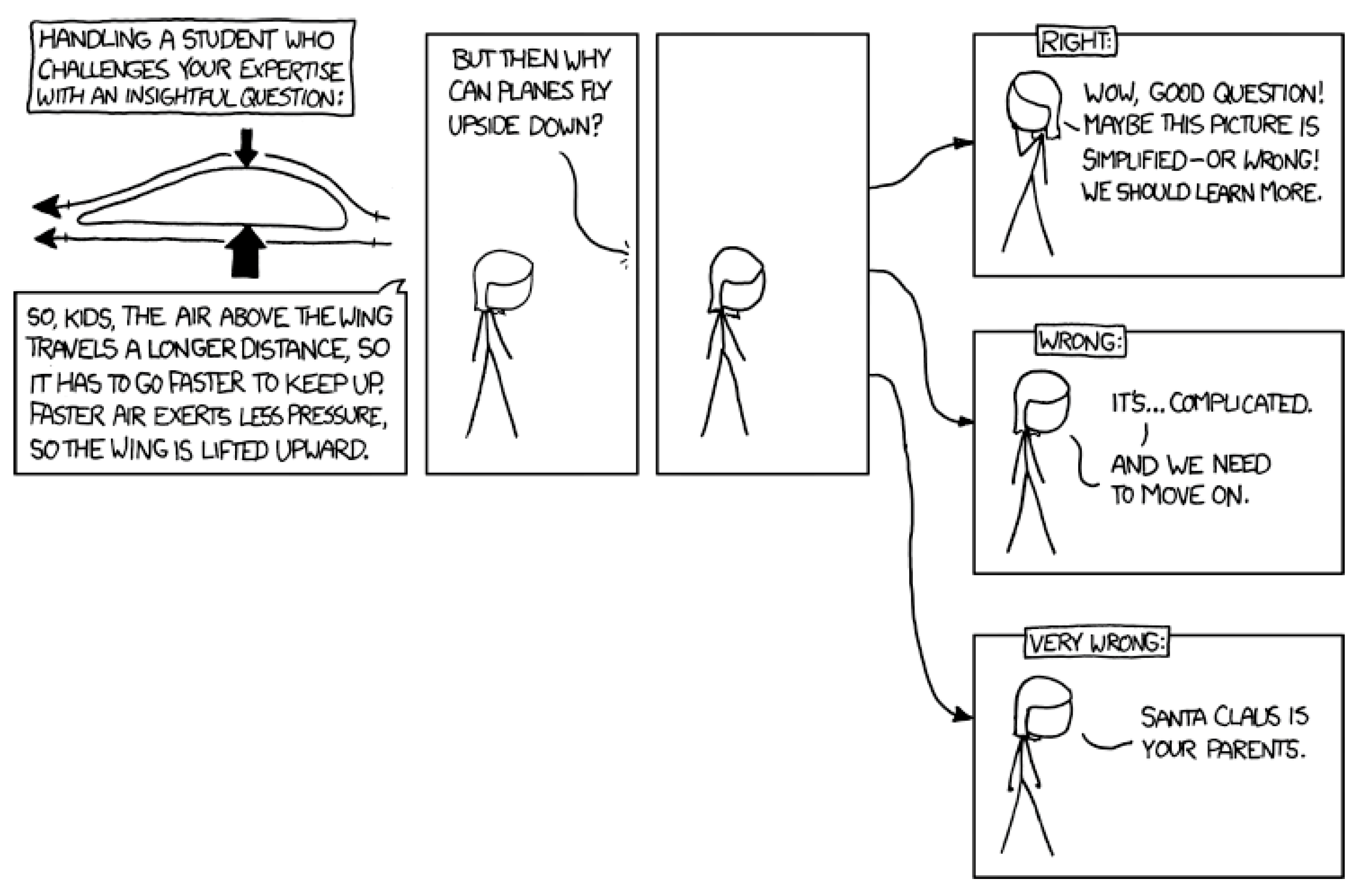
137] is very dismissive and does not really cause any skepticism or serious reflection; simply a reference that supports the Bernoulli approach is presented. This is a common theme in the debates that have occurred in the pages of journals. In principle, every criticism of every paper is worth serious contemplation, and most just reflexively respond with “here is some literature that supports my world view”. While the original XKCD cartoon about lift incorrectly uses the inverted flight argument (see
Figure 18), the underlying message is correct, and falsification and skepticism are cornerstones of the scientific method.
Linton presents a series of papers on all manner of aerodynamic phenomena for the education audience [
138,
139,
140]. Surprisingly, Linton cites Babinsky (2003) as the one responsible for exposing the misconceptions and fallacies around lift; it is clear from this review that countless authors have addressed this. Linton presents all-new aerodynamics [
138]; there is no sin or sine-squared law, but there are still invalid assumptions starting with Newton’s laws. By using traditional aerodynamics [
14], real power curves can be calculated and compared to Linton’s results, proving that his approach is incorrect. In fact, just looking at the values presented in Linton’s third figure, there is an obvious problem [
92]. The takeoff-induced power for the B747-400 can be correctly calculated as 21.3 MW (assuming a standard atmosphere and knowing the wing area, takeoff, speed, and takeoff weight, with a fundamental text such as Hurt [
58]). In contrast, Linton has calculated the induced power at more than 50 MW, more than twice the actual value. Similarly, knowing the lift-to-drag ratio, the cruise power can be determined using the same information; this is equal to 57 MW, and Linton has this at 90 MW, another significant margin of error. The following papers [
137,
138] are not at all representative of flapping wing aerodynamics [
141]; although they do provide qualifying statements in the conclusion.
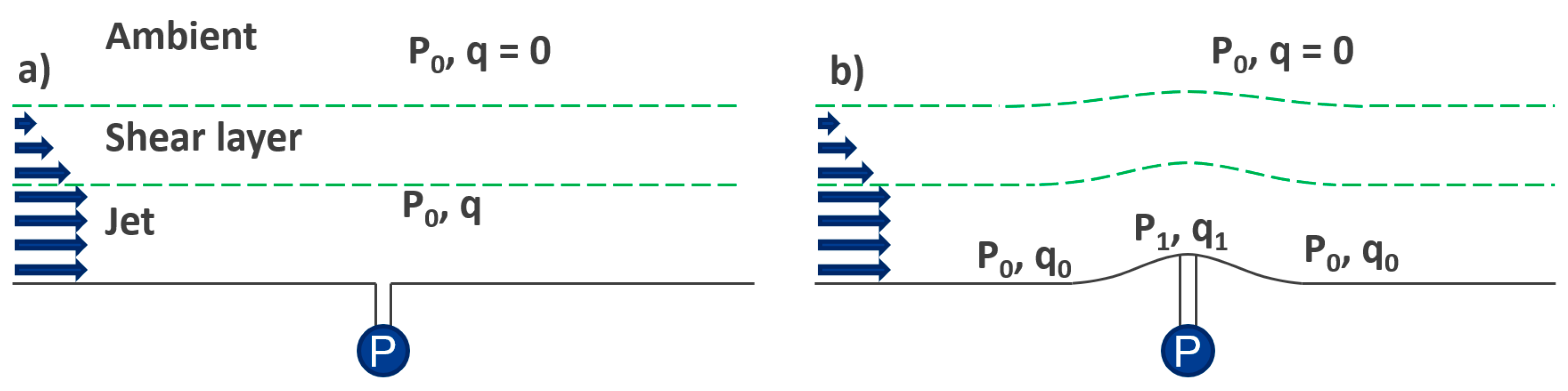
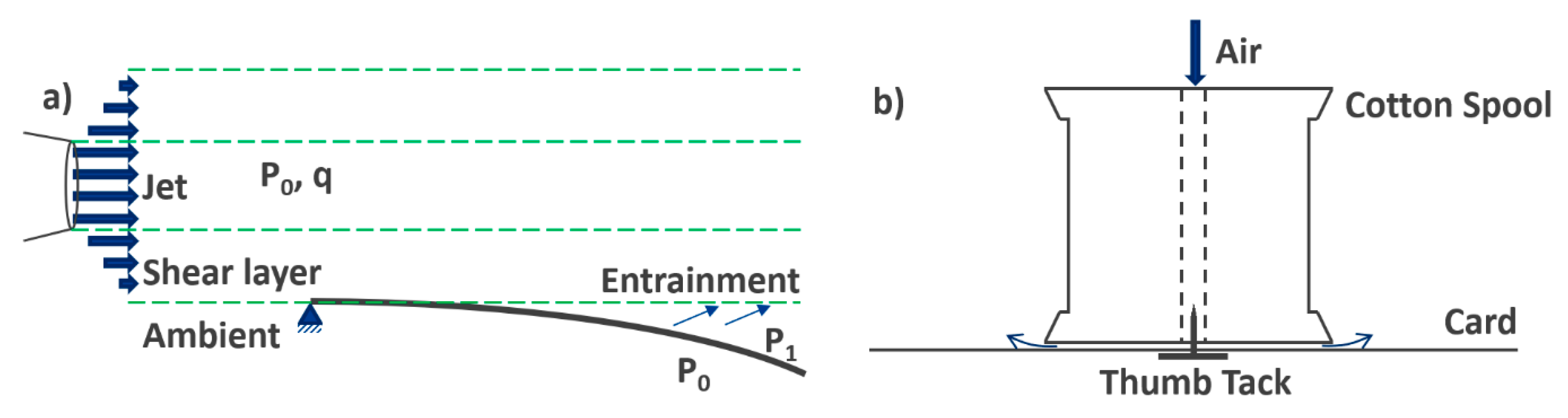
The third Bernoulli debate starts with Kamela [
142] and is much softer given that the author has read at least some of the prior debates and adjusted explanations to suit the growing body of knowledge. The letter from Eastwell [
143] highlights potential viscous effects. The reply by Kamela [
144] is very nice because it employs instrumentalism in that it uses the simple theory to estimate a value and uses a more detailed theory to predict a similar value. It should be noted that Bernoulli and the selected potential flow employed by Kamela are effectively the same theory, which is Newton’s Laws of Motion applied to inviscid fluids, so it is not surprising that they give the same result. The topic of discussion is how air blown across an orifice, which is flush to a flat surface, does not result in a reduction in pressure; instead, the orifice needs to be raised up to produce a reduction in pressure, as illustrated in
Figure 8. It should be noted that if entrainment were at work here as claimed by Eastwell, then the fluid in
Figure 8a would be drawn up, as the entrained air from inside the port would now be at a lower pressure. This is not observed, and, hence, entrainment (Coanda) is not needed to explain
Figure 8b.
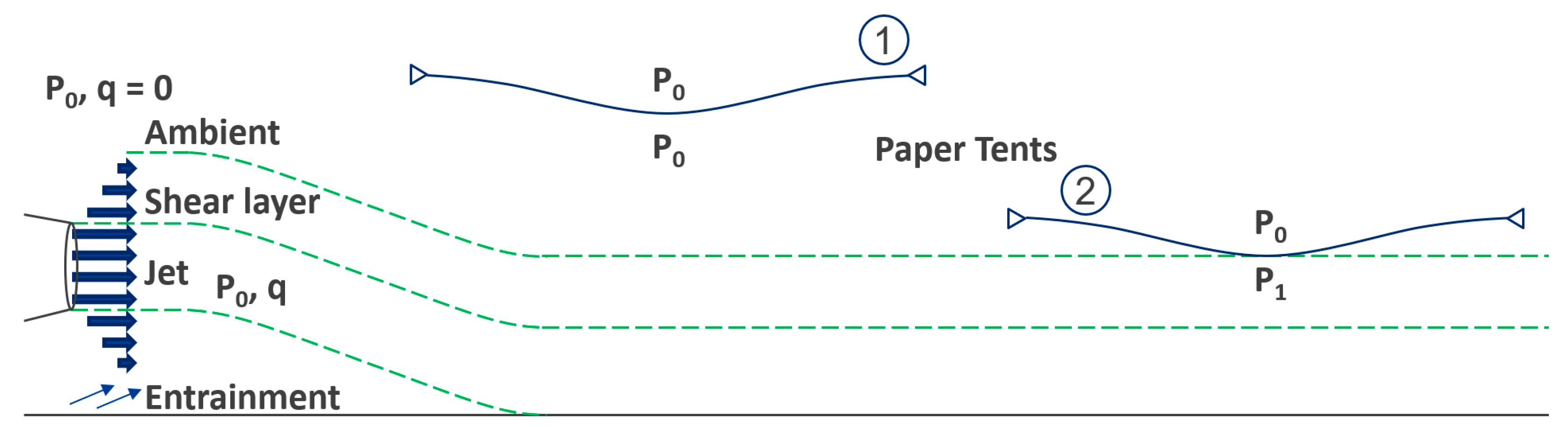
The third Bernoulli debate continues with McCarthy [
145], which is controversial, based on the quote, “Because of [Bernoulli’s] contribution… modern flight is possible”. While some fundamental aspects of fluid dynamics were observed and quantified by Bernoulli, flight is not possible because of those observations. This is the fundamental issue with using names on effects, principles, laws, equations, etc. Admittedly, the historical context of science is essential to science education, but given that McCarthy stresses the significance of language in the science context, the language in the history and education context must also be considered. McCarthy presents the equal transit time theory and Bernoulli to explain lift, with Bernoulli being the centerpiece of the article. The brief letter from Kerr [
146], noting equal transit time is incorrect, does not really add to the debate. The letter from Eastwell [
147] is more critical, pointing out potential issues with using Bernoulli to explain any of the four air-blowing activities presented by McCarthy. Eastwell simply states that by removing mention of Bernoulli and replacing it with entrainment (Coanda), the article can be saved. Given that the original article is not about aerodynamics but science education and history, with specific context to Bernoulli, one wonders if Eastwell understood the intent of the paper. The actual resolution to the problem is to correctly contextualize Bernoulli as the originator of these thoughts about moving fluids and pressure. A correct description of the paper tent is provided in
Section 3.1.2 above. Falsification requires Eastwell’s proposed pure Coanda explanation with Newton’s 3rd Law to explain all the cases; instead, he empirically justifies one (that uses curved surfaces) and then rationalizes to all four, noting that a paper tent does not involve a curved surface. Sadly, the response by McCarthy [
148] is worse than the criticism. As demonstrated in
Section 3.1.2, with sufficient knowledge, it is possible to contextualize Bernoulli along with Coanda to fix the entire content of the original paper; however, McCarthy simply uses uncertainty and confusion on the topic as a defense to pick and choose the preferred science that fits the narrative. To quote McCarthy “We, as science teachers, are left to decide…the explanation of lift that we wish our students to derive.” This is dangerous language that mirrors the attitudes and behaviors of climate change deniers, flat-earthers, and anti-vaxxers [
149].
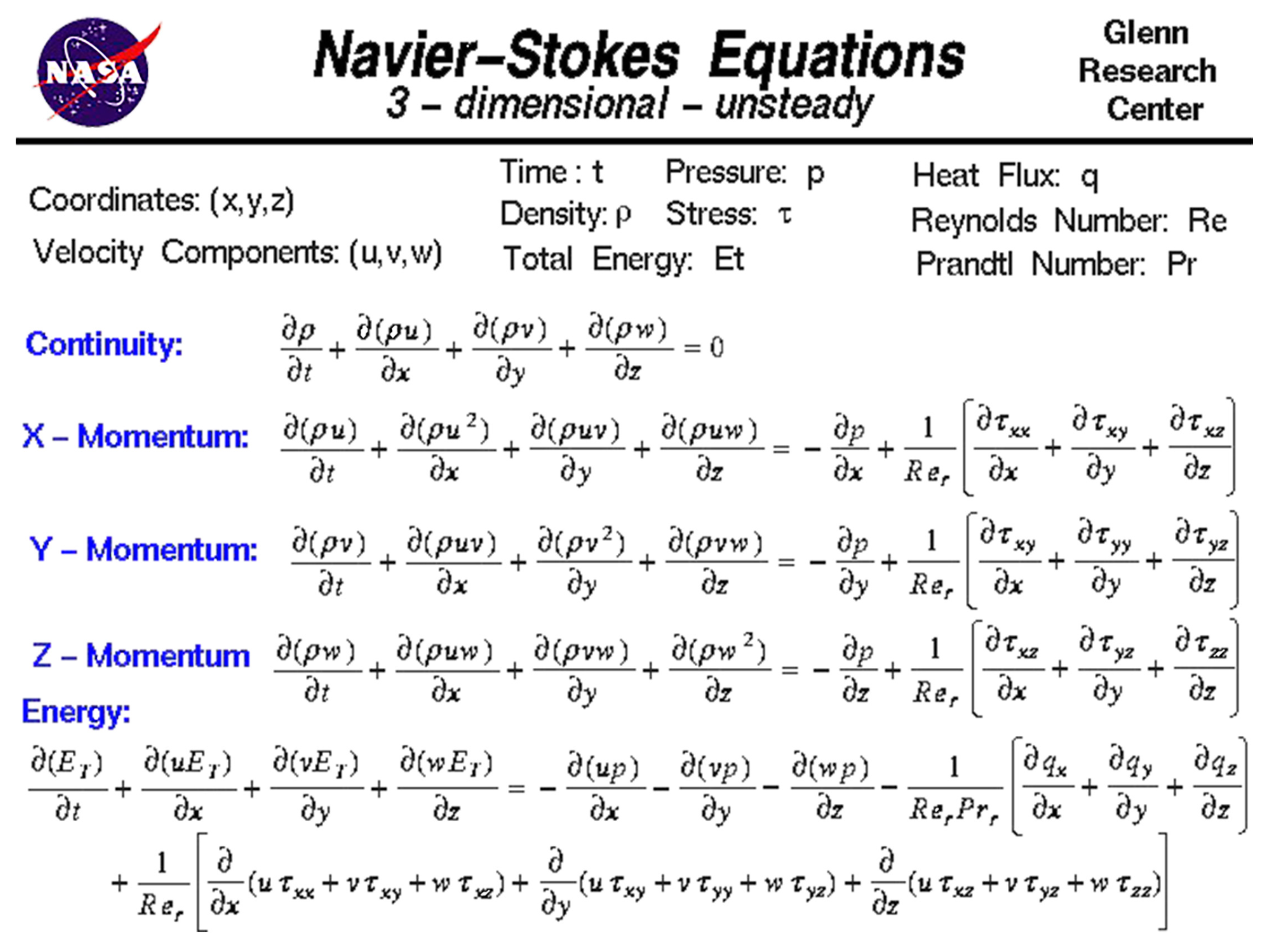
McCabe [
150] is interesting. The introduction starts well, putting Navier–Stokes front and center. The important limitation that Navier–Stokes describes the flow of a continuum, which, as a mathematical object, effectively embodies Zeno’s paradox (a continuum is infinitely divisible), is noted. It is known that air is made of discrete elements. However, at the scale of incompressible aerodynamics for aircraft, the predictive power of Navier–Stokes means it is the tool of choice for aircraft design. There are molecular models, such as lattice Boltzmann, and these are applied to hypersonic aerodynamics for spacecraft re-entry, etc. [
151]. Following this, McCabe proves that Bernoulli alone cannot explain lift, with a similar statement made for circulation alone. However, it is confusing if he is for or against Coanda; initially against Coanda, he states that “there is no genuine force of attraction between the wing surface and the boundary layer airflow”. In contrast, the second half of the article focuses heavily on Coanda in Formula 1 car aerodynamics.
López-Arias, et al. [
152] is the first in a series of papers by the group. In this, they are not concerned with aerodynamics and present “Coanda” in terms of the teapot effect. The apparatus they show facilitates a great quantitative investigation. However, as noted in
Section 3.1.3, the teapot effect demonstrates surface tension, and the two justifying citations used from the Journal of Fluid Mechanics are about fluid jets in the same fluid (air in air and water in water) and not as is presented here, water in air. The author’s following papers appear to inductively leap from the conclusion that the teapot effect is Coanda to a conclusion that Coanda explains lift [
153,
154]. This is supported by a reference to Anderson & Eberhardt. The authors state that viscosity is needed to accelerate the air; this is simply not true, the pressure gradient is the mechanism by which the flow is accelerated, and the viscosity provides an asymmetric acceleration above the airfoil relative to below. They go on to say that the viscous interactions that are important are those at the airfoils’ surface, and this is also not true. The induced upwash, which is greater in viscous fluids relative to inviscid ones, is occurring prior to the airfoil and so is clearly a fluid–fluid effect. Similarly, the Kutta condition, which is the other key viscous effect, is the fluid interacting with itself to create the starting vortex, resulting in the movement of the rear stagnation point. The authors then present similar experiments that have been in the literature since the 1980s and the first great debate about Bernoulli. Importantly the authors state “airplanes do not fly in air jets but are fully embedded by the flow”; however, this does not prevent them from claiming that their version of Weltner’s demonstration (using jets of air) is still an equivalent comparison to how a wing works. The self-citation is a clear indication that the authors do not see a difference between a water stream in air (their previous work) and the work they previously cited, which used jets of the same fluid (air jets in air or water jets in water), which fluid mechanists do! The viscometry experiment presented by the authors, which is in none of the preceding lift education literature, is a great addition. The lack of a Nobel Prize for Prandtl and the boundary layer cannot be stressed enough, and this experiment is a clear visual demonstration of this. The authors present the same experiments again in a following publication [
155]. In this article, they describe an aircraft as an “iron tube”, which is not a suitable word to use when describing an aircraft; metal, yes, given that aluminum is the primary metal, but steel (alloys of iron) is only 10% of the mass for a Boeing 787 and mostly in the engine. The authors’ flowing paper is a good example of an experiment to quantify the Coanda effect [
156]. In this, they now have a jet of air in air; hence, Coanda is applicable. The discussion of viscosity to explain the effect is also well presented. If there is a need to demonstrate and quantify Coanda, this approach is ideal. The final paper of the groups is interesting because it clearly, and correctly, states that Coanda is not applicable to how a wing works and is only applicable in terms of boundary layer flow control devices [
157].
Spathopoulos [
158] repeats many of the mistakes that others have before. The approach is an emphatic statement that Newton’s 3rd Law is all that is needed to explain lift, and then they state, ‘here is the traditional equation to quantify lift’, noting the presented equation cannot be derived directly from Newton. In fact, the coefficient of lift (C
L), which is the central feature of the equation as presented, was initially measured in a wind tunnel from pressure measurements and not measurements of airmass deflection.
A better approach to a wind tunnel with an open test section is presented by Heavers and Soleymanloo [
159]. This could be further improved with modern approaches to STEM. Šlégrová and Šlégr [
160] achieve similar things to the author before them who placed airfoils on stands on digital scales. However, they do so with a load cell attached to an Arduino, which is a great addition to a fundamental wind tunnel experiment, where the angle of attack could be controlled by the Arduino and the force on a load cell could be measured in response. Similarly, pitot tubes for drones can be connected to Arduinos, which would further add to a contemporary wind tunnel with automation and instrumentation. Liang and Wei [
161] produce a small wind-tunnel-like device. This is great with respect to the use of u-tube manometers to show pressure changes around the airfoil. However, there is a major flaw. The flow visualization is achieved with a “flexible” string. Since this is manually divided ahead of the airfoil, it does not allow for sufficient upwash at high angles of attack and, therefore, does not correctly illustrate the flow streamlines.
Brown and Friedrichsen [
162] present a more education-focused study. However, the underlying assumption for the experiments they use to tackle confusion is aerodynamics. As seen before in the literature, and debated previously, there are issues with using a pure Bernoulli explanation for aerodynamic demonstrations that involve blowing air. Coanda clearly needs to be considered. The confusion is exemplified in the proposed “molecule talk” the authors advocate. The simulation of internal flow within a venturi tube is used to show that random collisions between molecules are reduced when the streaming velocity is increased and the static pressure is decreased. This is true; the definition of pressure in the kinetic theory of gases is that it is related to random collisions. However, when there is a jet of air, the static pressure in the jet will equalize with the ambient air because the jet will expand to have the same static pressure, although it will have greater dynamic pressure because it has a velocity relative to the ambient air. As such, the random collisions inside the jet are the same as the random collisions in the ambient air. The thing missing in the “molecule talk” is the viscosity. The result of this is that the kinetic energy of the jet is transferred to the neighboring ambient air, entraining it into the flow and thereby reducing the pressure of the ambient air. It is not the jet that has less pressure; the jet pulls some ambient air along with it, thereby reducing the pressure around it. That explains the tent experiment and the flow attachment in the soda can experiment. Faulkner and Ytreberg [
163] also use a simulation of molecules to demonstrate pressures and velocity changes in a venturi.
Robertson [
164] presents a very strange introduction where Newton is not appliable because of forces that result in losses, a claim without a reference. On the topic of lift, Robertson takes an all-in approach with Bernoulli, Coanda, and streamline curvature combined. As with similar papers before, Robertson does not add anything to the literature, with the list of conclusions being the key features of Anderson & Eberhardt, although Robertson states that the ultimate reaction force for an aircraft is pressure at the earth’s surface, unlike Anderson & Eberhardt.
Jones [
165] provides another increment on the path of Coanda, not Bernoulli. While discussing how an air stream can levitate a cupcake, Jones unnecessarily adds an “impact” force, which is presumably a Newtonian ski effect. Recall Hewitt’s observation of dust on a simple fan; “impact” with the surface is not something associated with fluid flow. Lipscombe and Mungan [
166] is another contemporary Coanda and not Bernoulli paper, this time for blowing across pieces of paper as has been well established in the literature.
Deshpande and Sivapragasam [
167] and their companion paper [
168] achieve a similar outcome to the works of previous aerodynamicists before them, in the best way, with Navier–Stokes front and center. The authors do present an amusing paradox to the streamline curvature argument that is worth reading.
Singh, et al. [
169] present a formalization of the stream tube pinching model of lift, or what is referred to as the area difference model. Ultimately, the theory is developed due to a complete misunderstanding of how viscosity is involved in the creation of a starting vortex and how an airfoil, any airfoil, capable of creating lift at any angle of attack, will have a flow asymmetry, which is the missing element they seek.
Koumaras and Primerakis [
170] simply repeat the previous work by Kamala; however, they offer a Coanda explanation, as was discussed in the correspondence of Kamala’s work at the time. They have a
deus ex machina approach to Coanda, where it captures viscous effects and the continuum hypothesis; that is, there are no voids in a fluid. Consider water around a dolphin; if one of its fins were to become stalled, the flow “separates”, and it does not become a vacuum; there is not immediately an air pocket underwater. Stall or separation means there is a recirculation region where on average, relative to the free stream velocity, the stalled/separated flow is traveling backwards (see
Figure 4). Importantly, it must be noted that there is always fluid in that region; this is the nature of a continuum—it is smooth and continuous at the smallest scale. This is an issue for air, where we intuitively and incorrectly link lower pressures to lower densities, such that if there is a lower pressure in a region, we think of fewer molecules. Hence, the choice of a dolphin in water, given the notion of a vacuum or air pocket in deep water, is absurd. So, the Coanda effect does not describe this feature of fluid flow. Furthermore, the effect observed again by Koumaras & Primerakis can be explained by Bernoulli if applied correctly (see
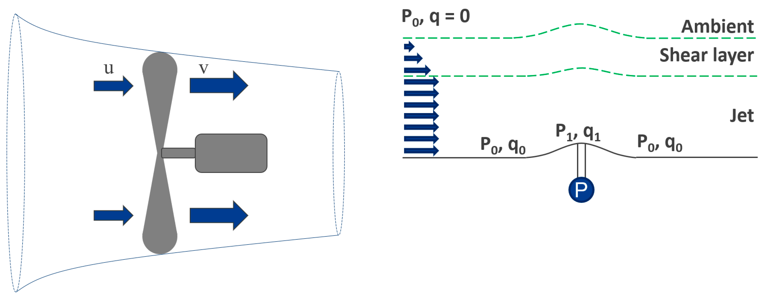
Figure 19). The neglected aspect of Bernoulli is that if a blower is used as the source of air, the air in that blower is the same air that is in the room. That is, it has the same static pressure, likely 101,325 Pa. This air is given kinetic energy, raising the total pressure of the fluid in the stream but not changing the static pressure. A stable jet in an ambient fluid will have the same static pressure; otherwise, it would also be subject to pressure gradient forces. So, the air that is blown across the flat orifice has static pressure P and dynamic pressure q, illustrated in
Figure 19. The test end feels this static pressure P, which, as just mentioned, is the same P at the reference end of the manometer. If that jet is then constricted as in a venturi effect, it will now have a higher q and a lower P; this means the P at the test end is now less than the P at the reference end, giving the measure difference in pressure. The likely point of confusion comes from the fact that we feel the wind from a fan. This is pressure; it is just not static pressure. It is dynamic pressure due to the flow speed.
McLean continues the tradition of qualified aerodynamicists trying to produce a top-down explanation of lift [
171,
172]. His proceeding book is a masterpiece [
18]. However, it is full to the brim with calculus, hence the reason for the two articles in
The Physics Teacher. McLean and the previous work by Lissaman as cited provide solid footing for not using a pure momentum transfer statement. Ultimately, McLean falls back on a heavily asterisked Newton’s Laws of Motion statement, which, based on the above readings, will likely result in misuse by those in Newton’s trenches against those in the Bernoulli trenches.
Mahajan [
173], as with many, incorrectly criticizes Bernoulli. Again, there is nothing in Bernoulli that relates longer path lengths, curved surfaces, or transit times to pressure, as referred to by Mahajan. Bernoulli is only a relationship between the total pressure (energy per unit volume), dynamic pressure (kinetic energy per unit volume), and static pressure. Bernoulli will correctly determine the pressure across an airfoil if an inviscid solution to the stream function of potential flow with circulation has been determined. This can then give the pressure coefficient along the top and bottom surfaces, which can be integrated to give the coefficient of lift. However, if you have neither pressure nor velocity, then Bernoulli can do nothing. These misconceptions are not unique to Mahajan; they have grown in the literature for decades, as camps for and against Bernoulli have grown and become entrenched. The poorly stated aspect of what Mahajan, and others against Bernoulli, point to is that pure Bernoulli explanations cannot describe the asymmetry in velocity around an airfoil. As such, those that do not understand fluids need to add additional elements to be able to support a Bernoulli statement. These additional elements are not part of Bernoulli; they are crutches used by those who do not understand enough about aerodynamics but who do know that aerodynamicists measure pressure differences to determine lift force.
Genz and Falconer [
174] discuss an expert-validated Flight Physics Concept Inventory (FliP-CoIn). This was presented in the preceding years at various conferences [
175,
176,
177]. It would be interesting to look at the inventory, the questions, and the solutions. As noted above, there are clear disagreements in the literature about flight concepts. The safest thing to do would be to avoid controversial aspects and focus on what is agreed upon. They found that “within one mind—naïve concepts can coexist with expert concepts”. Based on the presented body of knowledge from the literature and in the associated textbooks, this is not surprising. Several examples above have highlighted technical derivations, which are then undercut with an intuition that is a belief but not knowledge; however, that belief is forced into the ultimate definition presented. The main reason this is not surprising is that it is the same cognitive dissonance that exists with climate change deniers and many others [
178].
Wild [
8] discussed the origin of the equal transit time fallacy. This was accompanied by a discussion of potential flow, circulation, and Navier–Stokes to explain the flows associated with lift at those different levels. The fact that equal transit is a feature of pure potential flows is significant pedagogically, given the use of these methods in engineering is ubiquitous, albeit with the corrections noted in
Section 2.2. However, the concept that potential flows produce equal transit times is not documented in the corresponding texts utilized in aerodynamics education. Follow-up work demonstrated a low-cost accurate wind tunnel, which was used to demonstrate that the curved shape of the airfoil was not important to lift generation [
179]. The most recent work by Wild investigated illustrations in the educational literature of the flow around airfoils and wings [
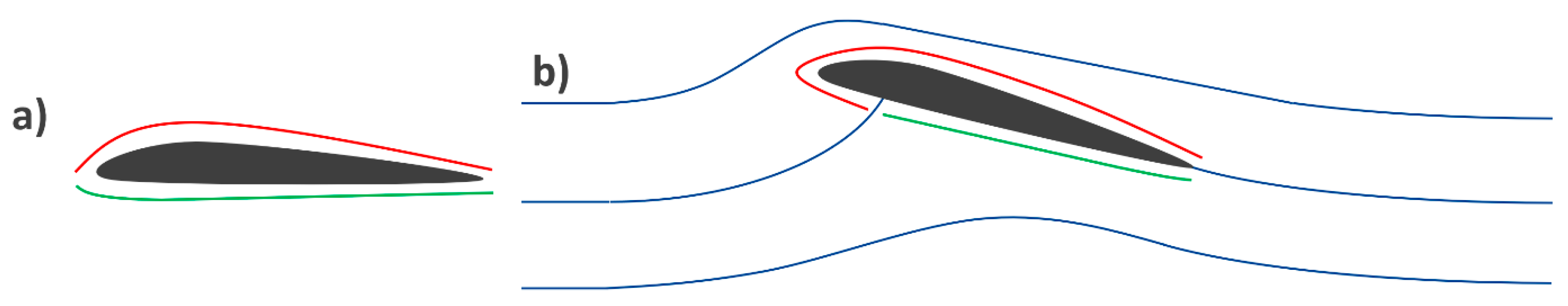
57]. It was found that more than half claiming to show flow around airfoils incorrectly illustrated flow around a wing. Of the cases, 28% did not include upwash, and 56% did not illustrate stagnation, resulting in significant confusion about the extent of flow asymmetry in lift production.


