Electrical Discharge Machining Non-Conductive Ceramics: Combination of Materials


 ,
, 
 and
and
Abstract
1. Introduction
- -
- the initiation of an electric pulse in the interelectrode gap,
- -
- the breakdown of the dielectric medium by a series of the discharge of pulses,
- -
- the formation of a discharge channel with a temperature of more than 10,000 °C of a cloud of low-temperature plasma,
- -
- the sublimation of material from the surface of the electrodes,
- -
- the interruption of the pulses and washing off the cooled-down erosion products out of the interelectrode gap by dielectric medium flows,
- -
- the restoration of dielectric tightness of the medium.
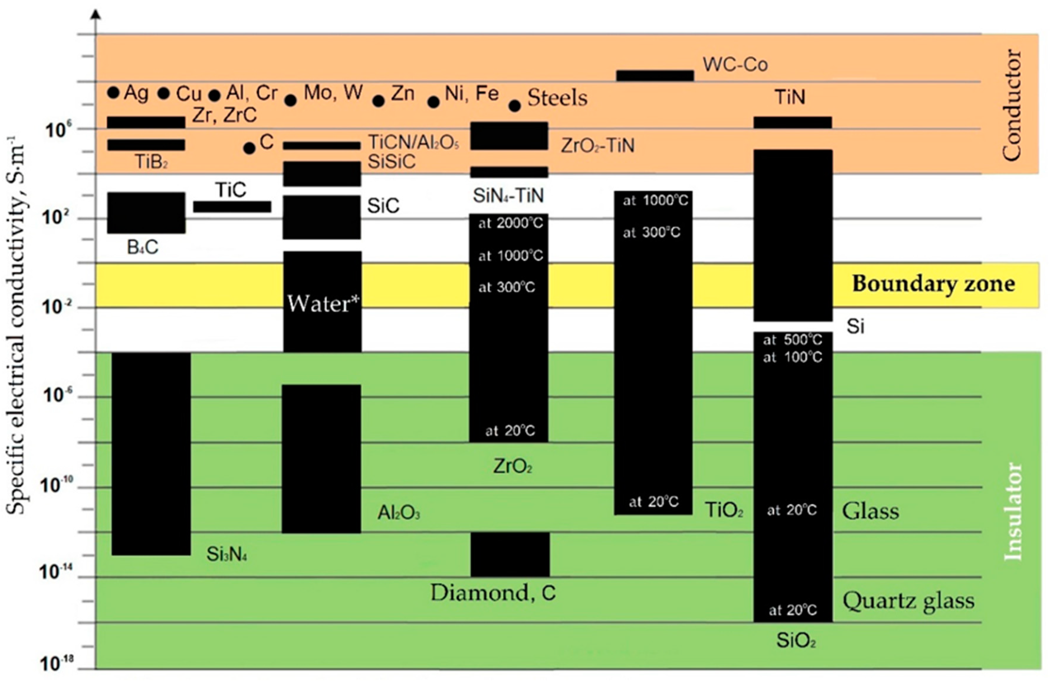
2. Conductivity of Materials and Saturation of Components in Recast Layer
3. Properties of Structural Ceramics in the Presence of Heat and Pressing Methods
4. Features of Structural Ceramics Sintering
5. Chemical Interaction of Ceramics Components with Electrodes, Powders, and Medium
6. Conclusions
Author Contributions
Funding
Acknowledgments
Conflicts of Interest
References
- Grigoriev, S.N.; Gurin, V.D.; Volosova, M.A.; Cherkasova, N.Y. Development of residual cutting tool life prediction algorithm by processing on CNC machine tool. Mater. Werkst. 2013, 44, 790–796. [Google Scholar] [CrossRef]
- Qudeiri, J.E.A.; Zaiout, A.; Mourad, A.-H.I.; Abidi, M.H.; Elkaseer, A. Principles and characteristics of different EDM processes in machining tool and die steels. Appl. Sci. 2020, 10, 2082. [Google Scholar] [CrossRef]
- Mouangue Nanimina, A.; Abdul-Rani, A.M.; Ahmad, F.; Zainuddin, A.; Jason Lo, S.H. Effects of Electro-discharge Machining on Aluminium Metal Matrix Composite. J. Appl. Sci. 2011, 11, 1668–1672. [Google Scholar] [CrossRef]
- Grigoriev, S.N.; Kozochkin, M.P.; Porvatov, A.N.; Volosova, M.A.; Okunkova, A.A. Electrical discharge machining of ceramic nanocomposites: Sublimation phenomena and adaptive control. Heliyon 2019, 5, e02629. [Google Scholar] [CrossRef] [PubMed]
- Grigoriev, S.N.; Melnik, Y.A.; Metel, A.S.; Panin, V.V. Broad beam source of fast atoms produced as a result of charge exchange collisions of ions accelerated between two plasmas. Instrum. Exp. Tech. 2009, 52, 602–608. [Google Scholar] [CrossRef]
- Grigoriev, S.; Metel, A. Plasma and beam-assisted deposition methods. In Nanostructured Thin Films and Nanodispersion Strengthened Coatings; Voevodin, A.A., Shtansky, D.V., Levashov, E.A., Moore, J.J., Eds.; Kluwer Academic Publishers: New York, NY, USA; Boston, MA, USA; Dordrecht, The Netherlands; London, UK; Moscow, Russia, 2004; pp. 147–154. [Google Scholar]
- Grigoriev, S.; Melnik, Y.; Metel, A. Broad fast neutral molecule beam sources for industrial-scale beam-assisted deposition. Surf. Coat. Tech. 2002, 156, 44–49. [Google Scholar] [CrossRef]
- Wijaya, H.; Wahyudi, S.; Soenoko, R.; Setyarini, P.H.; Yasid, S.; Gapsari, F. The effect of power supply current on recast layer in S45C steel using wire EDM. IOP Conf. Ser. Mater. Sci. Eng. 2019, 494, 012102. [Google Scholar] [CrossRef]
- Muthuramalingam, T. Measuring the influence of discharge energy on white layer thickness in electrical discharge machining process. Measurement 2019, 131, 694–700. [Google Scholar] [CrossRef]
- Tsai, D.C.; Lui, T.S.; Chen, L.H. Effect of graphite nodules on the EDM machinability of ferritic SG cast irons. Mater. Trans. JIM 2000, 41, 293–299. [Google Scholar] [CrossRef]
- Grigoriev, S.N.; Kozochkin, M.P.; Kropotkina, E.Y. Okunkova, A.A. Study of wire tool-electrode behavior during electrical discharge machining by vibroacoustic monitoring. Mech. Ind. 2016, 17, 717. [Google Scholar] [CrossRef]
- Betsofen, S. X-ray diffraction methods for the evaluation of residual stresses in the surface layers with gradient structure. Mater. Sci. 2006, 42, 367–375. [Google Scholar] [CrossRef]
- Markopoulos, A.P.; Papazoglou, E.-L.; Karmiris-Obratański, P. Experimental study on the influence of machining conditions on the quality of electrical discharge machined surfaces of aluminum alloy Al5052. Machines 2020, 8, 12. [Google Scholar] [CrossRef]
- Rahman, S.S.; Ashraf, M.Z.I.; Bashar, M.S.; Kamruzzaman, M.; Nurul Amin, A.K.M.; Hossain, M.M. Crystallinity, surface morphology, and chemical composition of the recast layer and rutile-TiO2 formation on Ti-6Al-4V ELI by wire-EDM to enhance biocompatibility. Int. J. Adv. Manuf. Technol. 2017, 93, 3285–3296. [Google Scholar]
- Umar Farooq, M.; Pervez Mughal, M.; Ahmed, N.; Ahmad Mufti, N.; Al-Ahmari, A.M.; He, Y. On the investigation of surface integrity of Ti6Al4V ELI using Si-mixed electric discharge machining. Materials 2020, 13, 1549. [Google Scholar] [CrossRef] [PubMed]
- Thangaraj, M.; Annamalai, R.; Moiduddin, K.; Alkindi, M.; Ramalingam, S.; Alghamdi, O. Enhancing the surface quality of micro titanium alloy specimen in WEDM process by adopting TGRA-based optimization. Materials 2020, 13, 1440. [Google Scholar] [CrossRef]
- Świercz, R.; Oniszczuk-Świercz, D. Investigation of the influence of reduced graphene oxide flakes in the dielectric on surface characteristics and material removal rate in EDM. Materials 2019, 12, 943. [Google Scholar] [CrossRef]
- Volosova, M.A.; Okunkova, A.A.; Povolotskiy, D.E.; Podrabinnik, P.A. Study of electrical discharge machining for the parts of nuclear industry usage. Mech. Ind. 2015, 16, 706. [Google Scholar] [CrossRef]
- Niamat, M.; Sarfraz, S.; Shehab, E.; Ismail, S.O.; Khalid, Q.S. Experimental characterization of electrical discharge machining of aluminum 6061 T6 alloy using different dielectrics. Arab. J. Sci. Eng. 2019, 44, 8043–8052. [Google Scholar] [CrossRef]
- Obrosov, A.; Gulyaev, R.; Zak, A.; Ratzke, M.; Naveed, M.; Dudzinski, W.; Weiß, S. Chemical and morphological characterization of magnetron sputtered at different bias voltages Cr-Al-C coatings. Materials 2017, 10, 156. [Google Scholar] [CrossRef]
- Bains, P.S.; Singh, S.; Sidhu, S.S.; Kaur, S.; Ablyaz, T.R. Investigation of surface properties of Al–SiC composites in hybrid electrical discharge machining. In Futuristic Composites, 1st ed.; Sidhu, S., Bains, P., Zitoune, R., Yazdani, M., Eds.; Springer: Singapore, 2018; pp. 181–196. [Google Scholar]
- Vozniakovskii, A.A.; Kidalov, S.V.; Kol’tsova, T.S. Development of composite material aluminum-carbon nanotubes with high hardness and controlled thermal conductivity. J. Compos. Mater. 2019, 53, 2959–2965. [Google Scholar] [CrossRef]
- Razeghiyadaki, A.; Molardi, C.; Talamona, D.; Perveen, A. Modeling of material removal rate and surface roughness generated during electro-discharge machining. Machines 2019, 7, 47. [Google Scholar] [CrossRef]
- Schubert, A.; Zeidler, H.; Hackert-Oschaetzchen, M.; Schneider, J.; Hahm, M. Enhancing micro-EDM using ultrasonic vibration and approaches for machining of nonconducting ceramics. Stroj. Vestn. J. Mech. Eng. 2013, 59, 156–164. [Google Scholar]
- Grigoriev, S.N.; Masterenko, D.A.; Teleshevskii, V.I.; Emelyanov, P.N. Contemporary state and outlook for development of metrological assurance in the machine-building industry. Meas. Tech. 2013, 55, 1311. [Google Scholar]
- Grigor’ev, S.N.; Kozochkin, M.P.; Fedorov, S.V.; Porvatov, A.N.; Okun’kova, A.A.; Kozochkin, M. Study of electroerosion processing by vibroacoustic diagnostic methods. Meas. Tech. 2015, 58, 878–884. [Google Scholar]
- Volosova, M.A.; Grigor’ev, S.N.; Kuzin, V.V. Effect of titanium nitride coating on stress structural inhomogeneity in oxide-carbide ceramic. Part 4. Action of heat flow. Refract. Ind. Ceram. 2015, 56, 91–96. [Google Scholar]
- Volosova, M.A.; Gurin, V.D. Influence of vacuum-plasma nitride coatings on contact processes and a mechanism of wear of working surfaces of high-speed steel cutting tool at interrupted cutting. J. Frict. Wear 2013, 34, 183–189. [Google Scholar]
- Fominski, V.Y.; Grigoriev, S.N.; Romanov, R.I.; Volosova, M.A.; Grunin, A.I.; Teterina, G.D. The formation of a hybrid structure from tungsten selenide and oxide plates for a hydrogen-evolution electrocatalyst. Tech. Phys. Lett. 2016, 42, 555–558. [Google Scholar]
- Volosova, M.A.; Grigoriev, S.N.; Ostrikov, E.A. Use of laser ablation for formation of discontinuous (discrete) wear-resistant coatings formed on solid carbide cutting tool by electron beam alloying and vacuum-arc deposition. Mech. Ind. 2016, 17, 720. [Google Scholar]
- Glaziev, S.Y. The discovery of regularities of change of technological orders in the central economics and mathematics institute of the soviet academy of sciences. Econ. Math. Methods 2018, 54, 17–30. [Google Scholar]
- Korotayev, A.V.; Tsirel, S.V. A spectral analysis of world GDP dynamics: Kondratiev waves, Kuznets swings, Juglar and Kitchin cycles in global economic development, and the 2008–2009 economic crisis. Struct. Dyn. 2010, 4, 3–57. [Google Scholar]
- Schumpeter, J.; Becker, M.C.; Knudsen, T. The fundamental phenomenon of economic development. Am. J. Econ. Sociol. 2002, 61, 405–437. [Google Scholar]
- Perez, C. Technological revolutions and techno-economic paradigms. Camb. J. Econ. 2010, 34, 185–202. [Google Scholar]
- Bobovich, B.B. Glass-fiber reinforced plastics—construction materials of the sixth technological paradigm? Glas. Ceram. 2019, 76, 38–41. [Google Scholar]
- Wonglimpiyarat, J. Towards the sixth Kondratieff cycle of nano revolution. Int. J. Nanotechnol. Mol. Comput. 2011, 3, 87–100. [Google Scholar]
- Lee, M.; Borom, M.P. Rapid rate sintering of Al2O3-TiC composites for cutting-tool applications. Adv. Ceram. Mater. 1988, 3, 38–44. [Google Scholar]
- Gao, L.; Hong, J.S.; Miyamoto, H.; Torre, S.D.D.L. Bending strength and microstructure of Al2O3 ceramics densified by spark plasma sintering. J. Eur. Ceram. Soc. 2000, 20, 2149–2152. [Google Scholar]
- Lukashenko, S.V.; Kovtun, A.V.; Dashuk, P.N.; Sokolov, B.N. The Method of Electrical Discharge Machining of Dielectrics. Patent 1,542,715, 10 December 1986. [Google Scholar]
- Mohri, N. EDM of advanced ceramics—From finish machining to machining insulating ceramics. CIRP Ann. Manuf. Technol. 1996, 45, 289–296. [Google Scholar]
- Lazarenko, B.R.; Lazarenko, N.I. A Method of Working Metals and Other Electro-Conductive Materials and Means for Applying Same. United Kingdom Patent GB637793A, 3 April 1943. [Google Scholar]
- Lazarenko, B.R.; Gitlevich, A.E.; Tkachenko, V.N. Certain characteristics of the discharge and plasma flow during the deposition of powdered coatings (Nekotorye Kharakteristiki Razryada I Plazmennogo Potoka Pri Nanesenii Pokrytii Iz Poroshkovykh Materialov). Surf. Eng. Appl. Electrochem. (Elektronnaya Obrabotka Materialov) 1974, 60, 29–31. [Google Scholar]
- Lazarenko, B.R.; Mikhailov, V.V.; Gitlevich, A.E.; Verkhoturov, A.D.; Anfimov, I.S. Distribution of elements in surface layers during electric spark alloying [Raspredelenie Elementov V Poverkhnostnykh Sloyakh Pri Elektroiskrovom Legirovanii]. Surf. Eng. Appl. Electrochem. (Elektronnaya Obrabotka Materialov) 1977, 3, 28–33. [Google Scholar]
- Lazarenko, B.R.; Duradzhi, V.N.; Bryantsev, I.V. Effect of Incorporating an additional inductance on the characteristics of anode and cathode processes (O Vliyanii Vklyucheniya Dopolnitel’noi Induktivnosti Na Kharakteristiki Anodnogo I Katodnogo Protsessov). Surf. Eng. Appl. Electrochem. (Elektronnaya Obrabotka Materialov) 1979, 5, 8–13. [Google Scholar]
- Lazarenko, B.R.; Lazarenko, N.I. Electric spark machining of metals in water and electrolytes. (Elektroiskrovaya Obrabotka Metallov V Vode I Elektrolitakh). Surf. Eng. Appl. Electrochem. (Elektronnaya Obrabotka Materialov) 1980, 1, 5–8. [Google Scholar]
- Tzeng, Y.F.; Lee, C.Y. Effects of powder characteristics on electrodischarge machining efficiency. Int. J. Adv. Manuf. Technol. 2001, 17, 586–592. [Google Scholar]
- Ivanov, R.; Hussainova, I.; Aghayan, M.; Drozdova, M.; Perez-Coll, D.; Carvajal Rodriguez, M.A.; Rubio-Marcos, F. Graphene-encapsulated aluminium oxide nanofibers as a novel type of nanofillers for electroconductive ceramics. J. Eur. Ceram. Soc. 2015, 35, 4017. [Google Scholar] [CrossRef]
- Liu, J.; Li, J.; Xu, C. Interaction of the cutting tools and the ceramic-reinforced metal matrix composites during micro-machining: A review. CIRP J. Manuf. Sci. Technol. 2004, 7, 55–70. [Google Scholar]
- Melnik, Y.A.; Kozochkin, M.P.; Porvatov, A.N.; Okunkova, A.A. On adaptive control for electrical discharge machining using vibroacoustic emission. Technologies 2018, 6, 96. [Google Scholar] [CrossRef]
- Baseri, H.; Sadeghian, S. Effects of nanopowder TiO2-mixed dielectric and rotary tool on EDM. Int. J. Adv. Manuf. Technol. 2016, 83, 519–528. [Google Scholar]
- Zhang, Y.; Wang, C.; Wang, Y.; Ni, Q.; Ji, L. Geometric Accuracy Improvement by Using Electrochemical Reaming with a Helical Tube Electrode as Post-Processing for EDM. Materials 2019, 12, 3564. [Google Scholar]
- Kozochkin, M.P.; Grigor’ev, S.N.; Okun’kova, A.A.; Porvatov, A.N. Monitoring of electric discharge machining by means of acoustic emission. Russ. Eng. Res. 2016, 36, 244–248. [Google Scholar]
- Yue, X.; Yang, X.; Tian, J.; He, Z.; Fan, Y. Thermal, mechanical and chemical material removal mechanism of carbon fiber reinforced polymers in electrical discharge machining. Int. J. Mach. Tools Manuf. 2018, 133, 4–17. [Google Scholar]
- Zasimchuk, E.; Baskova, O.; Gatsenko, O.; Turchak, T. Universal mechanism of viscoplastic deformation of metallic materials far from thermodynamics equilibrium. J. Mater. Eng. Perform. 2018, 27, 4183–4196. [Google Scholar]
- Ehle, L.C.; Schneider, S.; Schwedt, A.; Richter, S.; Klink, A.; Mayer, J. Electron microscopic characterization of surface zones thermo-chemically modified by electrical discharge machining. J. Mater. Process. Tech. 2020, 280, 116596. [Google Scholar]
- Faisal, N.; Kumar, K. Optimization of machine process parameters in EDM for EN 31 using evolutionary optimization techniques. Technologies 2018, 6, 54. [Google Scholar] [CrossRef]
- Gavrin, V.N.; Kozlova, Y.P.; Veretenkin, E.P.; Logachev, A.V.; Logacheva, A.I.; Lednev, I.S.; Okunkova, A.A. Reactor target from metal chromium for “pure” high-intensive artificial neutrino source. Phys. Part. Nucl. Lett. 2016, 13, 267–273. [Google Scholar]
- Porvatov, A.N.; Kozochkin, M.P.; Fedorov, S.V.; Okunkova, A.A. About possibility of vibroacoustic diagnostics of electrical discharge machining and characterization of defects. Mech. Ind. 2015, 16, 707. [Google Scholar] [CrossRef][Green Version]
- Kumar, A.S.; Durai, A.R.; Sornakumar, T. Machinability of hardened steel using alumina-based ceramic cutting tools. Int. J. Refract. Met. Hard Mater. 2003, 21, 109–117. [Google Scholar]
- Gevorkyan, E.; Lavrynenko, S.; Rucki, M.; Siemiatkowski, Z.; Kislitsa, M. Ceramic cutting tools out of nanostructured refractory compounds. Int. J. Refract. Met. Hard Mater. 2017, 68, 142–144. [Google Scholar]
- Wang, D.; Xue, C.; Cao, Y.; Zhao, J. Fabrication and cutting performance of an Al2O3/TiC/TiN ceramic cutting tool in turning of an ultra-high-strength steel. Int. J. Adv. Manuf. Technol. 2017, 91, 1967–1976. [Google Scholar]
- Laine, R.M.; Marchal, J.C.; Sun, H.P.; Pan, X.Q. Nano-α-Al2O3 by liquid-feed flame spray pyrolysis. Nat. Mater. 2006, 5, 710–712. [Google Scholar]
- Kolodiazhnyi, T.; Annino, G.; Spreitzer, M.; Taniguchi, T.; Freer, R.; Azough, F.; Panariello, A.; Fitzpatrick, W. Development of Al2O3–TiO2 composite ceramics for high-power millimeter-wave applications. Acta Mater. 2009, 57, 3402–3409. [Google Scholar]
- Evans, A.G. Perspective on the development of high-toughness ceramics. J. Am. Ceram. Soc. 1990, 73, 187–206. [Google Scholar]
- Boatemaa, L.; Bosch, M.; Farle, A.-S.; Bei, G.-P.; Van der Zwaag, S.; Sloof, W.G. Autonomous high-temperature healing of surface cracks in Al2O3 containing Ti2AlC particles. J. Am. Ceram. Soc. 2018, 101, 5684–5693. [Google Scholar]
- Ercenk, E.; Guven, B.; Yilmaz, S. Crystallization kinetics of machinable glass ceramics produced from volcanic basalt rock. J. Non-Cryst. Solids 2018, 498, 262–271. [Google Scholar]
- Song, Q.; Zhang, Z.-H.; Hu, Z.-Y.; Yin, S.-P.; Wang, H.; Wang, H.; Cheng, X.-W. Fully dense B4C ceramics fabricated by spark plasma sintering at relatively low temperature. Mater. Res. Express 2018, 5, 105201. [Google Scholar] [CrossRef]
- Li, L.; Pu, S.; Liu, Y.; Zhao, L.; Ma, J.; Li, J. High-purity disperse alpha-Al2O3 nanoparticles synthesized by high-energy ball milling. Adv. Powder Technol. 2018, 29, 2194–2203. [Google Scholar]
- Li, L. Effect of cyclic fatigue loading on matrix multiple fracture of fiber-reinforced ceramic-matrix composites. Ceramics 2019, 2, 327–346. [Google Scholar]
- Dassios, K.G.; Matikas, T.E. Assessment of fatigue damage and crack propagation in ceramic matrix composites by infrared thermography. Ceramics 2019, 2, 393–406. [Google Scholar]
- Ghouli, S.; Ayatollahi, M.R.; Bushroa, A.R. Fracture characterization of ceria partially stabilized zirconia using the GMTSN criterion. Eng. Fract. Mech. 2018, 199, 647–657. [Google Scholar]
- Ighodaro, O.L.; Okoli, O.I. Fracture toughness enhancement for alumina systems: A Review. Int. J. Appl. Ceram. Technol. 2008, 5, 313–323. [Google Scholar]
- Szutkowska, M.; Cygan, S.; Podsiadlo, M.; Laszkiewicz-Lukasik, J.; Cyboron, J.; Kalinka, A. Properties of TiC and TiN Reinforced Alumina-Zirconia Composites Sintered with Spark Plasma Technique. Metals 2019, 9, 1220. [Google Scholar]
- Zheng, G.; Zhao, J.; Gao, Z.; Cao, Q. Cutting performance and wear mechanisms of Sialon-Si3N4graded nano-composite ceramic cutting tools. Int. J. Adv. Manuf. Technol. 2012, 58, 19–28. [Google Scholar]
- Grigoriev, S.N.; Metel, A.S.; Melnik, Y.A.; Volosova, M.A. Equipment and Technology for Combined Ion–Plasma Strengthening of Cutting Tools. Machines 2018, 6, 58. [Google Scholar] [CrossRef]
- Orlova, A.I.; Ojovan, M.I. Ceramic mineral waste-forms for nuclear waste immobilization. Materials 2019, 12, 2638. [Google Scholar]
- Kachaev, A.A.; Grashchenkov, D.V.; Lebedeva, Y.E.; Solntsev, S.S.; Khasanov, O.L. Optically transparent ceramic (review). Glass. Ceram. 2016, 73, 117–123. [Google Scholar]
- Lyamina, G.V.; Ilela, A.E.; Dvilis, E.S.; Petyukevich, M.A.; Tolkachev, O.S. Medical ceramics from powders of the system Al2O3–ZrO2–Y2O3 obtained on an installation of nanospray drying. Nanotechnol. Russ. 2018, 13, 337–343. [Google Scholar]
- Gommeringer, A.; Kern, F. Mechanical properties and electrical discharge machinability of alumina-10 vol% zirconia-28 vol% titanium nitride composites. Ceramics 2020, 3, 199–209. [Google Scholar]
- Boulesteix, R.; Chevarin, C.; Belon, R.; Maître, A.; Cochain, L.; Sallé, C. Manufacturing of large size and highly transparent Nd: YAG ceramics by pressure slip-casting and post-sintering by HIP: An experimental and simulation study. Materials 2020, 13, 2199. [Google Scholar]
- Maksimov, R.N.; Khrustov, V.R.; Shitov, V.A.; Yurovskikh, A.S. Effect of the thermal shrinkage behavior of Yb:Lu2O3 nanopowder compacts on the structural and optical characteristics of ceramics. Inorg. Mater. 2019, 55, 634–639. [Google Scholar]
- Grishaev, V.V.; Tostanovskii, V.I. Properties of oxide structural ceramics made from mechanically milled powders. Refract. Ind. Ceram. 1993, 34, 98–102. [Google Scholar]
- Annenkov, Y.M.; Ivanov, V.V.; Ivashutenko, A.S.I.; Kondratyuk, A.A.; Sivkov, A.A. Efficiency of different compaction methods for corundum-zirconia powders. Refract. Ind. Ceram. 2008, 49, 461–465. [Google Scholar]
- Gavrilkin, S.M.; Kopaneva, L.I.; Batsanov, S.S. Anomalous phase transition in shock-compressed PbO. Combust. Explos. Shock Waves 2003, 39, 723–726. [Google Scholar]
- Grigoriev, S.N.; Dmitriev, A.M.; Korobova, N.V.; Fedorov, S.V. A cold-pressing method combining axial and shear flow of powder compaction to produce high-density iron parts. Technologies 2019, 7, 70. [Google Scholar] [CrossRef]
- Lazar, A.; Kosmač, T.; Zavašnik, J.; Abram, A.; Kocjan, A. TiN-nanoparticulate-reinforced ZrO2 for electrical discharge machining. Materials 2019, 12, 2789. [Google Scholar] [CrossRef]
- Morozova, L.V.; Kalinina, M.V.; Drozdova, I.A.; Shilova, O.A. Preparation and characterization of nanoceramics for solid oxide fuel cells. Inorg. Mater. 2018, 54, 79–86. [Google Scholar]
- Khasanov, O.L.; Pokholkov, Y.P.; Sokolov, V.M.; Dvilis, É.S.; Slosman, A.I.; Matrenin, S.V. Ultrasonic compacting of zirconium ceramics from ultradispersed powders. Glass. Ceram. 1995, 52, 177–180. [Google Scholar]
- Gadow, R.; Kern, F. Pressureless sintering of injection molded zirconia toughened alumina nanocomposites. J. Ceram. Soc. Jpn. 2006, 114, 958–962. [Google Scholar]
- Morozova, L.V.; Kovalko, N.Y.; Kalinina, M.V.; Shilova, O.A. Production of chemically pure zirconia-based nanoceramics in the ZrO2(Y2O3)-Al2O3 system for restorative dentistry. Theor. Found. Chem. Eng. 2019, 53, 848–854. [Google Scholar]
- Smirnov, V.V.; Smirnov, S.V.; Obolkina, T.O.; Antonova, O.S.; Goldberg, M.A.; Barinov, S.M. The influence of manganese oxide on the sintering and properties of the eutectic ceramics of the ZrO2-Al2O3-SiO2 system. Dokl. Chem. 2019, 486, 160–163. [Google Scholar]
- Morozova, L.V. Mechanochemical Activation of precursor powders for the preparation of dense Al2O3-ZrO2 <Y2O3> nanoceramics. Inorg. Mater. 2019, 55, 295–301. [Google Scholar]
- Novikov, Y.N. The FLASH Memory Based on Silicon Nitride (SONOS), 1st ed.; Nova Publisher: New York, NY, USA, 2011; pp. 35–66. [Google Scholar]
- Roman, O.V.; Kovalevskaya, A.V.; Fomikhina, I.V.; Grigoriev, S.V. Development of carbide and nitride ceramics of increased strength (Razrabotka karbidnoy i nitridnoy keramiki povyshennoy prochnosti). Lit’e Metall. 2005, 4, 157–162. [Google Scholar]
- Podbolotov, K.B.; Volochko, A.T.; Khort, N.A.; Gusarov, S.V. Refractory materials based on secondary resources and phosphate compounds. Refract. Ind. Ceram. 2019, 59, 579–582. [Google Scholar]
- Podbolotov, K.B.; Dyatlova, E.M.; Volochko, A.T. Synthesis and reinforcement of heat-resistant cordierite-mullite ceramic structure with introduction of a fiber filler. Refract. Ind. Ceram. 2016, 57, 151–154. [Google Scholar]
- Volochko, A.T.; Podbolotov, K.B.; Dyatlova, E.M. Refractory and Infusible Ceramics (Ogneupornye I Tugoplavkie Keramicheskie Materialy), 1st ed.; Belorus. Nauka: Minsk, Belarus, 2013; pp. 79–82. [Google Scholar]
- Makarov, A.V.; Skorynina, P.A.; Volkova, E.G.; Osintseva, A.L. Effect of heating on the structure, phase composition, and micromechanical properties of the metastable austenitic steel strengthened by nanostructuring frictional treatment. Phys. Met. Met. 2018, 119, 1196–1203. [Google Scholar]
- Borisov, M.; Lobanov, D.; Yanyushkin, A.; Skeeba, V. Investigation of the process of automatic control of current polarity reversal in the conditions of hybrid technology of electrochemical processing of corrosion-resistant steels. Obrab. Met.-Met. Work. Mater. Sci. 2020, 22, 6–15. [Google Scholar]
- Ojha, N.; Zeller, F.; Mueller, C.; Reinecke, H. The effect of the electrical discharge machining process on the material properties of nonconductive ceramics. J. Micro Nano-Manuf. 2016, 4, 1–5. [Google Scholar]
- Kumar, R.; Chaubey, A.K.; Maity, T.; Prashanth, K.G. Mechanical and tribological properties of Al2O3-TiC composite fabricated by spark plasma sintering process with metallic (Ni, Nb) binders. Metals 2018, 8, 50. [Google Scholar] [CrossRef]
- Godin, N.; Reynaud, P.; R’Mili, M.; Fantozzi, G. Identification of a critical time with acoustic emission monitoring during static fatigue tests on ceramic matrix composites: Towards lifetime prediction. Appl. Sci. 2016, 6, 43. [Google Scholar] [CrossRef]
- Grigoriev, S.N.; Krapostin, A.A. Multilayer composite nanoscale coatings as a method to increase reliability and tool life of cutting tools made of mixed ceramic Al2O3-TiC. Mech. Ind. 2016, 17, 704. [Google Scholar]
- Volosova, M.; Grigoriev, S.; Metel, A.; Shein, A. The Role of Thin-Film Vacuum-Plasma Coatings and Their Influence on the Efficiency of Ceramic Cutting Inserts. Coatings 2018, 8, 287. [Google Scholar] [CrossRef]
- Khodaee, A.; Melander, A. Numerical and experimental analysis of the gear size influence on density variations and distortions during the manufacturing of PM gears with an innovative powder processing route incorporating HIP. J. Manuf. Mater. Process. 2018, 2, 49. [Google Scholar] [CrossRef]
- Jayalakshmi, S.; Singh, R.A.; Gupta, M. Metallic glasses as potential reinforcements in Al and Mg matrices: A review. Technologies 2018, 6, 40. [Google Scholar]
- Balog, M.; Ibrahim, A.M.H.; Krizik, P.; Bajana, O.; Klimova, A.; Catic, A.; Schauperl, Z. Bioactive Ti plus Mg composites fabricated by powder metallurgy: The relation between the microstructure and mechanical properties. J. Mech. Behav. Biomed. 2019, 90, 45–53. [Google Scholar]
- Nicoara, M.; Buzdugan, D.; Locovei, C.; Bena, T.; Stoica, M. About thermostability of biocompatible Ti-Zr-Ag-Pd-Sn amorphous alloys. J. Therm. Anal. Calorim. 2018, 133, 189–197. [Google Scholar]
- Veronesi, P.; Rosa, R.; Colombini, E.; Leonelli, C. Microwave-Assisted preparation of high entropy alloys. Technologies 2015, 3, 182–197. [Google Scholar]
- Sezer, N.; Evis, Z.; Kayhan, S.M.; Tahmasebifar, A.; Koc, M. Review of magnesium-based biomaterials and their applications. J. Magnes. Alloy. 2018, 6, 23–43. [Google Scholar]
- Xanthopoulou, G.; Thoda, O.; Boukos, N.; Krishnamurthy, S.; Dey, A.; Roslyakov, S.; Vekinis, G.; Chroneos, A.; Levashov, E. Effects of precursor concentration in solvent and nanomaterials room temperature aging on the growth morphology and surface characteristics of ni–nio nanocatalysts produced by dendrites combustion during SCS. Appl. Sci. 2019, 9, 4925. [Google Scholar] [CrossRef]
- Volykhov, A.A.; Sanchez-Barriga, J.; Sirotina, A.P.; Neudachina, V.S.; Frolov, A.S.; Gerber, E.A.; Kataev, E.Y.; Senkovsky, B.; Khmelevsky, N.O.; Aksenenko, A.Y.; et al. Rapid surface oxidation of Sb2Te3 as indication for a universal trend in the chemical reactivity of tetradymite topological insulators. Chem. Mater. 2016, 28, 8916–8923. [Google Scholar]
- Grigoriev, S.N.; Kozochkin, M.P.; Sabirov, F.S.; Kutin, A.A. Diagnostic systems as basis for technological improvement. Proc. CIRP 2012, 1, 599–604. [Google Scholar]
- Ferreira, S.C.; Conde, A.; Arenas, M.A.; Rocha, L.A.; Velhinho, A. Anodization mechanism on sic nanoparticle reinforced al matrix composites produced by power metallurgy. Materials 2014, 7, 8151–8167. [Google Scholar]
- Xu, C.; Liu, F.; Huang, L.; Jiang, L. Dependence of creep performance and microstructure evolution on solution cooling rate in a polycrystalline superalloy. Metals 2018, 8, 4. [Google Scholar] [CrossRef]
- Iankov, R. Finite element simulation of powder metal compaction processes in container with several punches. Nato Sci. Ser. 2001, 176, 169–180. [Google Scholar]
- Sobol, O.V.; Andreev, A.A.; Grigoriev, S.N.; Gorban’, V.F.; Volosova, M.A.; Aleshin, S.V.; Stolbovoy, V.A. Physical characteristics, structure and stress state of vacuum-arc tin coating, deposition on the substrate when applying high-voltage pulse during the deposition. Probl. Atom. Sci. Tech. 2011, 4, 174–177. [Google Scholar]
- Loh, N.J.; Simao, L.; Jiusti, J.; De Noni, A., Jr.; Montedo, O.R.K. Effect of temperature and holding time on the densification of alumina obtained by two-step sintering. Ceram. Int. 2017, 43, 8269–8275. [Google Scholar]
- Tamura, Y.; Moshtaghioun, B.M.; Gomez-Garcia, D.; Rodríguez, A.D. Spark plasma sintering of fine-grained alumina ceramics reinforced with alumina whiskers. Ceram. Int. 2017, 43, 658–663. [Google Scholar]
- Jin, Y.; Han, M.-K.; Kim, S.-J. Na-Doping effects on thermoelectric properties of Cu2−xSe nanoplates. Appl. Sci. 2018, 8, 12. [Google Scholar] [CrossRef]
- Ning, J.; Wu, D.; Zhao, D. Synthesis and thermoelectric properties of TiO2/Cu2SnSe3 composites. Appl. Sci. 2017, 7, 1043. [Google Scholar]
- Alleno, E. Review of the thermoelectric properties in nanostructured Fe2Val. Metals 2018, 8, 864. [Google Scholar] [CrossRef]
- Zhang, H.; Zhang, L.; Liu, X.; Chen, Q.; Xu, Y. Effect of Zr addition on the microstructure and mechanical properties of CoCrFeNiMn high-entropy alloy synthesized by spark plasma sintering. Entropy 2018, 20, 810. [Google Scholar] [CrossRef]
- Viswanathan, V.; Laha, T.; Balani, K.; Agarwal, A.; Seal, S. Challenges and advances in nanocomposite processing techniques. Mater. Sci. Eng. R 2006, 54, 121–285. [Google Scholar]
- Wang, L.; Zhang, J.; Jiang, W. Recent development in reactive synthesis of nanostructured bulk materials by spark plasma sintering. Int. J. Refract. Met. Hard Mater. 2013, 39, 103–112. [Google Scholar]
- Zhang, Y.F.; Wang, L.J.; Jiang, W.; Chen, L.-D. Microstructure and properties of Al2O3-TiC composites fabricated by combination of high-energy ball milling and spark plasma sintering (SPS). J. Inorg. Mater. 2005, 20, 1445. [Google Scholar]
- Oraei, M.; Mostaan, H.; Rafiei, M.; Abbasian, A.R.; Zarezadeh, M. Investigation into microstructural evolutions, mechanical properties and thermal analysis of Al (Zn)/Al2O3 nano-composite fabricated by mechanical milling and SPS method. Mater. Res. Express 2019, 6, 0865g9. [Google Scholar]
- Moriceau, J.; Houizot, P.; Pasturel, M.; Guizouarn, T.; Rouxel, T. A magnetic glass matrix (ZnO-BaO-B2O3) particulate (Fe3O4) nanocomposite obtained by SPS. J. Non Cryst. Solids 2019, 514, 116–121. [Google Scholar]
- Fedorov, S.V.; Pavlov, M.D.; Okunkova, A.A. Effect of structural and phase transformations in alloyed subsurface layer of hard-alloy tools on their wear resistance during cutting of high-temperature alloys. J. Frict. Wear 2013, 34, 190–198. [Google Scholar]
- Chaudhary, T.; Siddiquee, A.N.; Chanda, A.K. Effect of wire tension on different output responses during wire electric discharge machining on AISI 304 stainless steel. Def. Technol. 2019, 15, 541. [Google Scholar] [CrossRef]
- Maradia, U.; Filisetti, E.; Boccadoro, M.; Roten, M.; Dutoit, J.-M.; Hengsberger, S. Increasing the injection moulding productivity through EDM surface modulation. Proc. CIRP 2018, 68, 58. [Google Scholar] [CrossRef]
- Uhlmann, E.; Oberschmidt, D.; Bolz, R. Application of micro structured, boron doped CVD-diamond as mu EDM tool electrodes. Proc. CIRP 2018, 68, 649. [Google Scholar]
- Sahu, A.K.; Chatterjee, S.; Nayak, P.K.; Mahapatra, S.S. Study on effect of tool electrodes on surface finish during electrical discharge machining of Nitinol. IOP Conf. Ser. Mater. Sci. Eng. 2018, 338, 012033. [Google Scholar]
- Prathipati, R.P.; Devuri, V.; Cheepu, M.; Gudimetla, K.; Kiran, R.U. Machining of AISI D2 tool steel with multiple hole electrodes by EDM process. IOP Conf. Ser. Mater. Sci. Eng. 2018, 330, 012067. [Google Scholar]
- Trung, K.H. Development of a WEDM system with high machining efficiency. Int. Conf. Syst. Sci. Eng. 2017, 397–399. [Google Scholar] [CrossRef]
- Wu, H.; Wang, T.; Wang, J. Research on discharge state detection of finishing in high-speed wire electrical discharge machine. Int. J. Adv. Manuf. Technol. 2019, 103, 2301. [Google Scholar]
- Takale, A.; Chougule, N. Optimization of process parameters of wire electro discharge machining for Ti49.4Ni50.6 shape memory alloys using the Taguchi technique. Int. J. Struct. Integr. 2019, 10, 548. [Google Scholar] [CrossRef]
- Reshetnikov, S.; Kurzina, I.; Livanova, A.; Meshcheryakov, E.; Isupova, L. Effect of Li, Na and K modification of alumina on its physical and chemical properties and water adsorption ability. Materials 2019, 12, 4212. [Google Scholar] [CrossRef]
- Konishcheva, M.V.; Svintsitskiy, D.A.; Potemkin, D.I.; Rogozhnikov, V.N.; Sobyanin, V.A.; Snytnikov, P.V. Catalytic performance and characterization of highly efficient composite Ni(Cl-x)/CeO2/eta-Al2O3/FeCrAl wire mesh catalysts for preferential CO methanation. Chemistryselect 2020, 5, 1228–1234. [Google Scholar]
- Kholodnaya, G.; Sazonov, R.; Ponomarev, D.; Zhirkov, I. Pulsed plasma chemical synthesis of carbon-containing titanium and silicon oxide based nanocomposite. Radiat. Phys. Chem. 2018, 144, 132–137. [Google Scholar]
- Matveev, V.A.; Kalinnikov, V.T.; Zakharov, V.I.; Maiorov, D.V. Investigation of an effect exerted by methods of production of chromium(III) oxides-hydroxides on their physicochemical properties. Russ. J. Appl. Chem. 2011, 84, 1524–1528. [Google Scholar]
- Yang, J.; Liu, Y.; Deng, J.; Zhao, X.T.; Zhang, K.F.; Han, Z.; Dai, H.X. AgAuPd/meso-Co3O4: High-performance catalysts for methanol oxidation. Chin. J. Catal. 2019, 40, 837–848. [Google Scholar]
- Shiryaev, M.A.; Jin, Y.J.; Bong, H.C.; Baranov, A. ZnO nanoparticle modification by polyethylenimine for biomolecule conjugation. Nanotechnol. Russ. 2017, 12, 613–619. [Google Scholar]
- Gavelova, P.; Halodova, P.; Namburi, H.K.; Prokupkova, I.A.; Miklos, M.; Krejci, J. From micro to nano: Material characterization methods for testing of nuclear core and structural materials. J. Nucl. Eng. Radiat. Sci. 2019, 5, 030917. [Google Scholar] [CrossRef]
- Olenin, A.Y.; Lisichkin, G.V. Surface-modified oxide nanoparticles: Synthesis and application. Russ. J. Gen. Chem. 2019, 89, 1451–1476. [Google Scholar]
- Voroshilov, Y.V.; Gorshkova, L.V.; Popova, A.M.; Fedorov, T.F. Ternary systems Ti-Zr-C and Ti-Hf-C. Sov. Powder Met. 1967, 6, 403–405. [Google Scholar]
- Bulienkov, N.A.; Zheligovskaya, E.A.; Chernogorova, O.P.; Drozdova, E.I.; Ushakova, I.N.; Ekimov, E.A. Nonequilibrium diamond growth during the high-temperature high-pressure synthesis of a composite material made of a mixture of cobalt and fullerene powders. Russ. Met. 2018, 1, 35–41. [Google Scholar]
- Titkov, Y.; Berdnikova, O.; Tyurin, Y.; Kolisnichenko, O.; Polovetskiy, Y.; Kushnaryova, O. Effect of structure on the properties of composite Cr3C2 + NiCr coatings. Springer Proc. Phys. 2020, 240, 151–159. [Google Scholar]
- Zotti, G.; Cattarin, S.; Mengoli, G.; Fleischmann, M.; Peter, L.M. Photoelectrochemistry of copper(I) acetylide films electrodeposited onto copper electrodes. J. Electroanal. Chem. 1986, 200, 341–351. [Google Scholar]
- Denisov, E.T.; Sarkisov, O.M.; Likhtenshtein, G.I. Chemical Kinetics: Fundamentals and Recent Developments, 1st ed.; Elsevier Science: Amsterdam, The Netherlands, 2008; pp. 472–486. [Google Scholar]
- Zirconium (Zirconiy). Chemical Encyclopedia (Khimicheskaya Enciklopediya), 1st ed.; Zefirov, N.S., Kulov, N.N., Eds.; Great Russian Encyclopedia (Bolshaya Rossiyskaya Enciklopediya): Moscow, Russia, 1998; Volume 5. [Google Scholar]
- Li, X.F.; Hu, Z.Y.; Huang, B. Phase diagram and superconductivity of compressed zirconium hydrides. Phys. Chem. Chem. Phys. 2017, 19, 3538–3543. [Google Scholar] [PubMed]
- Sukhushina, I.S. Phase transitions of the ZrNiH x hydride. Russ. J. Phys. Chem. A 2007, 81, 1595–1600. [Google Scholar]
- Besedin, D.V.; Ustynyuk, L.Y.; Ustynyuk, Y.A.; Lunin, V.V. Hydrogenolysis and hydroisomerization of neopentane on titanium and zirconium hydrides stabilized on the surface of SiO2: A theoretical study by density functional theory. Russ. J. Phys. Chem. A 2008, 82, 193–200. [Google Scholar]
- Grigoriev, S.; Kozochkin, M.; Porvatov, A.; HtuM, T.; Zhavoronsky, P.; Jiang, X.; Pivkin, P. Dynamic model of electrical discharge machining and algorithm of extreme control through acoustic signal. EPJ Web. Conf. 2019, 224, 05002. [Google Scholar] [CrossRef][Green Version]
- Grigoriev, S.N.; Fedorov, S.V.; Hamdy, K. Materials, properties, manufacturing methods and cutting performance of innovative ceramic cutting tools—A review. Manuf. Rev. 2019, 6, 19. [Google Scholar]
- Fedotov, P.S.; Ermolin, M.S.; Karandashev, V.K.; Ladonin, D.V. Characterization of size, morphology and elemental composition of nano-, submicron, and micron particles of street dust separated using field-flow fractionation in a rotating coiled column. Talanta 2014, 130, 1–7. [Google Scholar]
- Makarova, O.V.; Palatnikov, M.N.; Biryukova, I.V.; Sidorov, N.V. Impact of a dopant impurity electronic structure on physical properties, defect structure, and features of lithium niobate doping technology. Tech. Phys. 2019, 64, 1872–1878. [Google Scholar]
- Ikim, M.I.; Spiridonova, E.Y.; Belysheva, T.V.; Gromov, V.F.; Gerasimov, G.N.; Trakhtenberg, L.I. Structural properties of metal oxide nanocomposites: Effect of preparation method. Russ. J. Phys. Chem. B 2016, 10, 543–546. [Google Scholar]
- Brauer, G.; Baudler, M.; Fehér, F. Handbuch der Präparativen Anorganischen Chemie, 3rd ed.; Enke: Stuttgart, Germany, 1978. [Google Scholar]
- Kovtunenko, P.V.; Nesterova, I.L. Tin oxides. In Chemical Encyclopedia (Khimicheskaya Enciklopediya), 1st ed.; Knunyants, I.L., Ed.; Great Russian Encyclopedia (Bolshaya Rossiyskaya Enciklopediya): Moscow, Russia, 1992; Volume 3, pp. 515–548. [Google Scholar]
- Gommeringer, A.; Kern, F.; Gadow, R. Enhanced mechanical properties in ED-Machinable Zirconia-Tungsten carbide composites with Yttria-Neodymia Co-Stabilized zirconia matrix. Ceramics 2018, 1, 26–37. [Google Scholar]
- Samsonov, G.V.; Vinitskiy, I.M. Refractory Compounds (Handbook) (Tugoplavkie Soedineniya (Spravochnik)), 1st ed.; Mettalurgiya: Moscow, Russia, 1976; p. 560. [Google Scholar]


| Physical, Mechanical and Electro Properties | Al2O3 | ZrO2 | Si3N4 | Stainless Steel * |
|---|---|---|---|---|
| Density (ρ), g/cm3 | 3.8–4.0 | 6.0–6.05 | 2.37–3.25 | 7.6–7.95 |
| Melting point, °C | 2044 | 2715 | 1900 | 1420 |
| Flexural strength (σ), MPa | 300–350 | 750–1050 | 650–800 | 110–550 |
| Vickers hardness (HV), GPa | 19–21 | 12–13 | 16–19.6 | 0.129 |
| Fracture strength (k1c), Pa·m½ | 3.0–3.5 | 8.0–10.0 | 6.5–7.2 | - |
| Thermal conductivity (k), W·m−1·K−1 | 25–30 | 2–3 | 10–43 | 30–45 |
| Thermal expansion coefficient (α), 10−6·K−1 | 8.0–9.0 | 10.0–11.0 | 1.4–3.7 | 9.9–17.3 |
| Dielectric permittivity (ε), F/m | 9.5–10 | ~25 | ~7–7.5 | - |
| Specific electrical conductivity (ς20°) at room temperatures (20 °C), S·m−1 | 1.0 × 10⁻¹⁰–1.0 × 10⁻¹² | 1.0 × 10⁻⁶–1.0 × 10⁻⁸ | 1.0 × 10⁻⁴–1.0 × 10⁻¹³, minimal volume electrical resistivity (χ, Ω·m) 19 at 20 °C | 0.5–0.8 × 10⁷ |
| Specific electrical conductivity (ς1000°) in the presence of high temperatures (1000 °C), S·m−1 | No more than 1.0 × 10⁻⁶, electrical conductivity is higher in powder materials due to impurities, at low pressures - n-type semiconductor | 1.0–10.0 | Workability up to 1350 °C, min volume electrical resistivity (χ, Ω·m) 15 at 200 °C, 12 at 600 °C; that corresponds to 6.7 × 10⁻² and 8.3 × 10⁻² [95,96,97] | 0.81–0.86 × 10⁻¹⁰ |
| Auxiliary Electrode | Dielectric Medium | Chemical Properties in the Presence of Heat |
|---|---|---|
| Al2O3 ceramics [19,20,21,22,138,139,140,141,142,143] | ||
| Any | Water | It is stable up to 2044 °C, chemically stable, insoluble in water, at 1000 °C it can interact with alkali metals to form aluminates as NaAlO2, which react with water: NaAlO2 + 2H2O → NaOH + Al(OH)3 During fusion, it can form anhydrous aluminates, for example, Ca(AlO2)2, which with water can form calcium hydroaluminates, CaO·Al2O3·H2O therefore it can only be processed in distilled and deionized water |
| Oil/Kerosene | Aluminum carbide Al4C3 is obtained by direct reaction: 4Al + 3C → Al4C3 Or in the reaction of alumina Al2O3 with carbon C in the presence of heating to 1800 °C: 2Al2O3 + 9C → Al4C3 + 6CO↑ It is steady up to 1400 °C, reacts with water: Al4C3 + 12H2O → 4Al(OH)3↓ + 3CH4↑ With hydrogen at 2200 °C: Al4C3 + 6H2↑ → 4Al + 3CH4↑ With oxygen at 650–700 °C: Al4C3 + 6O2↑ → 2 Al2O3 + 3CO2↑ It is used in pyrotechnics | |
| Ti, Cr, Co, C | Water | Titanium(IV) dioxide TiO2 becomes a semiconductor at 1000 °C with specific electrical conductivity up to 103 S·m−1 |
| Chromium(II) oxide CrO decomposes into metallic chromium and chromium(III) oxide at 697 °C: 3CrO → Cr2O3 + Cr Hydrogen is reduced to metallic chromium at 1000 °C: CrO + H2↑ → Cr + H2O Chromium(II) oxide Cr2O3 is resistant up to 2440 °C, toxic and causes dermatitis on contact with skin, is used as abrasive and catalyst in a number of organic reactions; in a strongly acidic environment, a reaction may occur: Cr2O3 + 6H+ + 9H2O → 2[Cr(H2O)6]3+ Strong reducing agents reduce it: Cr2O3 + 2Al → Al2O3 + 2Cr Chromium(IV) oxide CrO2 is obtained by heating hydrated chromium(III) oxide Cr2O3 in oxygen at 350–400 °C: Cr2O3·nH2O + O2↑ → 4CrO2 + 2nH2O It decomposes on heating at 420–510 °C: 4CrO2 → 2Cr2O3 + O2↑ It reacts with water at 100 °C: 3CrO2 + 2H2O → 2CrO(OH) + H2CrO4 3CrO2 → Cr2O3 + CrO3 Chromium(VI) oxide CrO3 has the melting point at 196 °C, when it is dissolved in water, chromic acid is formed with a lack of CrO3: CrO3 + H2O → H2CrO4 It forms dichromic acid in water with an excess of CrO3: 2CrO3 + H2O → H2Cr2O7 It decomposes with the formation of chromium(III) oxide and oxygen at 250 °C: 4CrO3 → 2Cr2O3 + 3O2↑ | ||
| Cobalt oxide Co3O4 is a complex oxide having a spinel structure and stable at room temperature; it decomposes with the formation of cobalt monoxide CoO at temperatures above 900 °C The α-form or β-form of cobalt monoxide CoO can be obtained at high temperatures All cobalt oxide Co3O4 is reduced with hydrogen: Co3O4 + 4H2↑ → 3Co + 4H2O | ||
| Aluminum carbide Al4C3 can be formed | ||
| Zn, Ag, Au, Al | Water | Zinc oxide ZnO sublimates at a temperature of 1800 °C, when fused with silicon dioxide forms a refractory glassy silicate ZnSiO3 |
| Silver(I) oxide Ag2O decomposes when heated above 280 °C Silver(I,III) oxide Ag2O2 decomposes when heated above 100 °C | ||
| Gold(I) oxide Au2O is unstable under normal conditions, decomposes in Au and Au2O3 at 225 °C Gold(II) oxide Au2O3 is stable, has excellent conductive properties, is used in microelectronics | ||
| Alumina Al2O3 is insoluble in water, is an n-type dielectric or semiconductor at nominal pressure | ||
| ZrO2 ceramics [144,145,146,147,148,149,150] | ||
| Any | Any | Becomes a semiconductor in the presence of temperatures |
| The released zirconium has the property to burn in oxygen at a self-ignition temperature of 250 °C with high speed and smokeless, which is why it has become widespread in pyrotechnics | ||
| The released zirconium actively absorbs hydrogen forming hydrides ZrHx at 250–300 °C [151] that can develop super-conducting properties under pressure of 150 GPa at 10.6 K [152]; the hydrides dissociate at 1200–1300 °C | ||
| Water | Does not interact with water | |
| Ti, Cr, Co, C | Most of the possible components’ interactions are similar to the mentioned above | |
| The sublimation point of carbon C is 3642 °C; it does not exist in liquid form at normal pressures | ||
| Zirconium forms zirconium carbide ZrC with carbon C, which is an excellent conductor, at temperatures above 900 °C; its electrical properties are similar to those of pure zirconium | ||
| Zn, Ag, Au, Al | Most of the components’ interactions are similar to the mentioned above | |
| Any | Oil/Kerosene | It forms zirconium carbide ZrC at temperatures above 900 °C |
| Ti, Cr, Co, C | The formed titanium carbide TiC has a slightly higher electrical resistance than titanium nitride, a semiconductor, becomes a conductor with increasing temperature | |
| Chromium carbide Cr3C2 has the specific electrical conductivity * of 1.3 × 10⁶ S·m−1; chromium carbides have melting point in the range of 1520–1890 °C; chromium carbide Cr7C3 turns into Cr23C6 after prolonged heating at 730–870 °C; Cr3C2 carbide insoluble in water but it can interact with zinc Zn at a temperature of 940 °C; the oxidation of chromium carbide begins at temperatures of 700–1100 °C | ||
| Tricobalt carbide Co3C in the presence of 3Co + C at a temperature of 1800 °C decomposes upon crystallization. At temperatures above 230 °C, tricobalt carbide reacts with hydrogen to form methane at 250 °C, while methane and metallic cobalt are released | ||
| Copper(I) acetylenide Cu2C2 in dry form is explosive, detonates when heated or impact, forms hydrates in the presence of water Cu2C2·H2O Copper(II) acetylenide CuC2 forms hydrates in the presence of water CuC2·½H2O, insoluble in water, but decomposes with explosion upon drying and loss of water | ||
| Zn, Ag, Au, Al | Zinc carbide ZnC2 reacts with water to form acetylene (colorless flammable gas): ZnC2 + 2H2O → Zn(OH)2 + C2H2↑ | |
| Silver acetylide Ag2C2 (CAg≡CAg) is a very unstable and explosive compound, explodes when heated and mechanically exposed | ||
| Gold carbide Au2C2 is insoluble in water and explosive, with ammonia forms an explosive adduct Au2C2·NH3 | ||
| Assisting Powder | Dielectric Medium | Chemical Properties in the Presence of Heat |
|---|---|---|
| Al2O3 ceramics | ||
| + conductive additives | ||
| W | Water | Tungsten W is heat- and chemically resistant under standard conditions; the sublimation point is 3422 °C; it exists in liquid form only at high pressures; it is slowly oxidized to tungsten(VI) trioxide WO3 at a temperature of red heat; oxidation of tungsten W in an atmosphere of oxygen occurs at temperatures above 500 °C: 2W + 3O2↑ → 2WO3 It is reduced to metallic tungsten W by hydrogen at a temperature of 700–900 °C |
| Cu | Melting point is 1083.4 °C, it is oxidized to copper(I) oxide Cu2O, which does not react with water and dissociates to a small degree, with oxygen deficiency at a temperature of 200 °C: 4Cu + O2↑ → 2Cu2O and to copper(II) oxide CuO with oxygen excess at temperatures of about 400–500 °C or by heating metallic copper in the air at temperatures below 1100 °C: 2Cu + O2↑ → 2CuO Copper(II) oxide CuO is reduced to metallic copper by hydrogen (exothermic reaction): CuO + H2↑ → Cu + H2O + Q↑ It also decomposes into copper Cu and oxygen O, when heated to 1100 °C | |
| + oxide ceramics | ||
| TiO2 | Water | As was mentioned above, titanium(IV) dioxide TiO2 becomes a semiconductor at 1000°C with electrical conductivity up to 103 S·m−1 |
| CeO2 | Cerium(IV) dioxide CeO2 has a relatively high ionic conductivity of oxygen at 500–800°C; it also exhibits high electronic conductivity at low oxygen partial pressures; melting point is 2400 °C; refectory material up to 2300 °C in an oxidizing or inert atmosphere; cerium(IV) oxide reduces to cerium(III) oxide Ce2O3 with hydrogen gas at about 1400 °C: 2CeO2 + H2↑ → Ce2O3 + H2O And, on the contrary, cerium(III) oxide is oxidized to cerium(IV) oxide with an excess of oxygen: 2Ce2O3 + O2↑ → 4CeO2 Cerium(III) oxide Ce2O3 is stable on air, but cerium Ce in powder is pyrophoric and unstable at room temperature; presence cerium as an alloying element for aluminum alloy reduces its conductivity; the melting point is 2177 °C Cerium Ce reacts fulminant with some metals as zinc Zn at higher temperatures and forms intermetallides with heat and light emission; thus using a brass tool is not recommended for EDM in the presence of cerium Ce | |
| SnO2 | Tin(IV) oxide is a wide-gap n-type semiconductor, electrical resistivity 3.4 × 10³ Ω·cm (electrical conductivity ~2.94 × 10² S·m−1); doping with elements of group V (for example, antimony Sb) increases electrical conductivity by three-five orders of magnitude; the melting point is 1630 °C; it evaporates with the decomposition of tin monoxide SnO (and its di-, tri- and tetramers) and oxygen at high temperatures; it is restored by hydrogen to metal tin at 500–600 °C: SnO2 + 2H2↑ → Sn + 2H2O | |
| ITO | Indium tin oxide (ITO) is semiconductor material with n-type conductivity comparable to metallic, where tin ions serve as electron donors; it is a solid solution of 90% indium(III) oxides and 10% tin(IV) (In2O3)0.9−(SnO2)0.1; insoluble in water and extremely expensive in applications due to its transparency | |
| ZrO2 ceramics | ||
| + conductive additives | ||
| WC | Any | The specific electrical conductivity * is ~5.22 × 10² S·m− 1; significant and rapid oxidation of tungsten carbide WC in air begins at 500–700 °C, and it is completely oxidized due to the high volatility of tungsten oxide at temperatures above 800 °C: WC + 2O2 → WO3 + CO↑ Tungsten(VI) trioxide WO3 is reduced as well to metallic tungsten W by hydrogen H as it was mentioned above The temperature stability range for W2C is up to 2750 °C; it is up to 2600 °C for WC; WC weakly interacts with a zinc melt at a temperature of 940 °C |
| Oil/Kerosene | Tungsten(VI) trioxide WO3 is reduced as well to metallic tungsten W by carbon C at a temperature of 1000 °C | |
| TiC | Any | Melting point is ~3260 °C; it begins to react with nitrogen N at high temperatures above 2500 °C; it is decarburized during interacting with hydrogen H; the temperature of the active oxidation of titanium carbide is 1100–1200 °C; the temperature stability range of titanium carbide TiC is below 3140 °C; it is highly resistant to molten low-melting metals and metals such as copper, aluminum, brass, cast irons and steels |
| Oil/Kerosene | It is oxidized by carbon dioxide CO2 at temperatures above 1200 °C | |
| Cu | Oil/Kerosene | It should be noted to the mentioned above that copper(II) oxide CuO is reduced as well to copper Cu by carbon(II) monoxide CO and carbon C: 2CuO + C → 2Cu + CO2↑ |
| + oxide ceramics | ||
| TiO2 | Oil/Kerosene | As it was mentioned above, the formed titanium carbide TiC has a slightly higher electrical resistance than titanium nitride TiN (less electrically conductive); it is a semiconductor; it becomes a conductor with increasing temperature |
| CeO2 | Cerium(IV) oxide is reduced by carbon(II) monoxide CO to cerium(III) oxide, when there is not enough oxygen: 4CeO2 + 2CO → 2Ce2O3 + 2CO2↑ The contrary reaction as presented in (27) | |
| SnO2 | It should be added to the mentioned above, it is restored as well by carbon to metal tin at 800–900 °C: SnO2 + 2C → Sn + 2CO↑ | |
© 2020 by the authors. Licensee MDPI, Basel, Switzerland. This article is an open access article distributed under the terms and conditions of the Creative Commons Attribution (CC BY) license (http://creativecommons.org/licenses/by/4.0/).
Share and Cite
Volosova, M.A.; Okunkova, A.A.; Fedorov, S.V.; Hamdy, K.; Mikhailova, M.A. Electrical Discharge Machining Non-Conductive Ceramics: Combination of Materials. Technologies 2020, 8, 32. https://doi.org/10.3390/technologies8020032
Volosova MA, Okunkova AA, Fedorov SV, Hamdy K, Mikhailova MA. Electrical Discharge Machining Non-Conductive Ceramics: Combination of Materials. Technologies. 2020; 8(2):32. https://doi.org/10.3390/technologies8020032
Chicago/Turabian StyleVolosova, Marina A., Anna A. Okunkova, Sergey V. Fedorov, Khaled Hamdy, and Mariya A. Mikhailova. 2020. "Electrical Discharge Machining Non-Conductive Ceramics: Combination of Materials" Technologies 8, no. 2: 32. https://doi.org/10.3390/technologies8020032
APA StyleVolosova, M. A., Okunkova, A. A., Fedorov, S. V., Hamdy, K., & Mikhailova, M. A. (2020). Electrical Discharge Machining Non-Conductive Ceramics: Combination of Materials. Technologies, 8(2), 32. https://doi.org/10.3390/technologies8020032