Abstract
The rapid evolution of smart assisted living operations in combination with the blooming of commercial robots calls for the use of robotic based systems. Specifically, certain circumstances such as the handling of critical, contagious virus outbreaks like the recent novel Coronavirus epidemic can be benefited by an assisting mobile robot system controlled remotely, complementing measures like the isolation of patients from medical stuff. Within this context, the robotic-based solution to be employed needs to be easy to deploy, able to manufacture with low cost, and able to operate with ease by non-trained personnel. Also, to address the needs of existing hospitals, traditional or smart ones, as well as the temporary risk management facilities in, for example, quarantined cities, ease of integration in terms of size and infrastructure requirements is a must. In this work, the design and implementation of a robotic chassis bearing an arm manipulator is presented, addressing all these needs efficiently. Special attention has been given to the ease of teleoperation with minimal need for equipment and expertise, utilizing a Leap Motion virtual reality sensor which outweighs Microsoft’s Kinect capabilities. Furthermore, a reconfigurable hardware and software integrated system has been used to control the communication, algorithm processing and motion control utilizing a Xilinx Zynq system on chip (SoC).
1. Introduction
In the era of smart things, the concept of automation has entered all places where human effort needs to and can be reduced. In this context, smart hospitals have emerged in an effort to cope with the need for better treatment of a continuously growing population. At the same time, recent infectious disease outbreaks have paved the way for adopting state-of-the-art technology advances, providing new means to oversee more efficient and safe treatment in isolation rooms for both patients and medical/nursing staff [1]. Special circumstances such as sterile emergency rooms, as well as the handling of hazardous materials and by-products make the existence of tele-operated machines with human-like ability skills a necessity [2,3]. For this reason, a mobile platform with navigation and interaction potential within a hospital environment, able to carry healthcare related items and interact with objects close to it in an autonomous way, would be a suitable solution [4,5]. Furthermore, this platform should be able to connect and communicate its information to a smart infrastructure via Internet of things (IoT) (Figure 1).
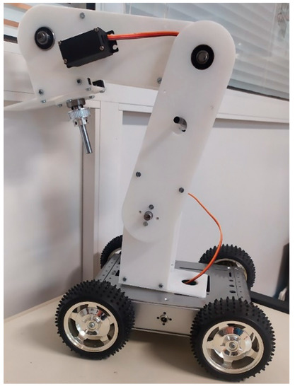
Figure 1.
Robotic System Overview.
Isolated sterile room are spaces where patients should avoid contact with other not infected people. This includes both other patients and medical stuff. Complete isolation cannot be achieved as there are operations which need human effort. These operations could be reduced by utilizing a scheme of a human like manipulator with teleoperation [6]. Of course, to adapt this approach to the given place of interest, we should consider the lack of technical know-how of the staff and the need for minimal contact of machines with humans [7]. This can be achieved by taking advantage of emerging virtual reality sensing technologies. In contrast to standard solutions which use joysticks [8] or even newer wearable approaches, a motion sensor overseeing a hand movement from a distance and extracting position and movement information can make the operation of the system exhibit very low complexity.
In addition, experience has proved that such infrastructure is not always needed in a large quantity unless times of crisis occur. In such cases the need for this kind of equipment grows exponentially as victims can range from tens to even whole cities. For this reason, the designed system has been kept to a low cost implementation which can be produced at a large scale and especially able to be integrated easily in every environment. This has been achieved by moving away from industrial multi axis positioning systems [9] standards and utilizing modern approaches like 3D printed parts, off the self-components, and newer processors combining control, communication, and flexibility for a lower price. Regarding the control unit, more capable and less expensive processors can move the complexity from the electromechanical parts to the control circuit, allowing for enhancing the operation of less expensive actuators at the cost of development time [10].
These important features are characterizing the proposed (AP-SoC based) robotic system that will be presented in the following sections (Figure 2). This article is organized as follows: It includes a system description section (Section 2) with its main parts, each in a subsection, namely Section 2.1, “Robotic Chassis” where the moving base of the robotic platform is discussed, Section 2.2 “ Robotic arm manipulator” in which the specifications of the main part of the system is presented leading to specific implementation choices, Section 2.3 “Leap Motion Sensor”, and Section 2.4 “Zynq [11] APSoC controller”, each describing the main novelties in the sensing and processing logic of the system. Also, Section 3 “Implementation Description”, with Section 3.1 “Software” and Section 3.2 “Hardware”, dive into the technical details of how the functionality is implemented, describing also the tools and the steps that are needed for embedding all the subsystems to a working prototype. Finally, ideas for future work regarding the integration of this robot in a more complicated use case such as a complete living assistant are discussed, and the paper ends with the conclusion section.
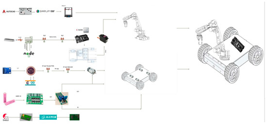
Figure 2.
System Overview.
2. System Description
2.1. Robotic Chassis
The base of the robotic platform consists of a 4-wheeled vehicle (Figure 3) which has the ability to move effectively not only inside a room but also into a predefined hospital floor.
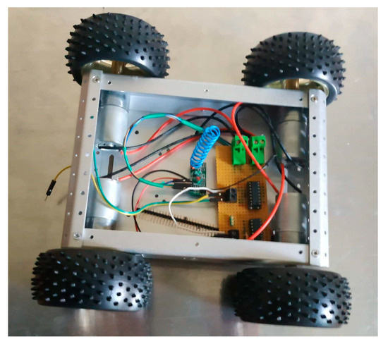
Figure 3.
Chassis top view with motors and receiver.
The designed vehicle is equipped with sensing devices and the appropriate remote control so as to serve primal design objectives. Its characteristics offer a number of capabilities that allow for the implementation of path planning algorithms for movement from point-A to point-B as well as for environment awareness scenarios, such as interaction concerning any obstacle or human [12].These autonomous scenarios need the addition of ultrasonic sensors and deployment of software algorithms in a future work implementation but justify the selection of our programmable controllers and their extended capabilities analyzed in the next chapters. High torque is employed so as to be able to cope with the whole weight of a robotic arm as well as the medical equipment to be conveyed [13]. The motors used for the vehicle movement are cheap dc motors with the appropriate gearboxes which ensure both low-cost and high precision via low speeds and high torque owed to the high gear ratio. These are implemented by employing custom logic for driving the corresponding voltages. This is loosening the requirement for human effort and, in certain circumstances, this feature proves to be very useful, if not a necessity, such as in cases where infectious deceases call for quarantines. A recent example is evidently the 2019 novel Coronavirus (2019-nCoV) situation. Robots and intelligent medical care solutions have earned their spurs towards the direction of fighting pneumonia, a severe complication of this virus [14]. In this context, robots used are equipped with an internal disinfection system that can release disinfection gas. Such a machine as the one described in this work can autonomously navigate and replace human workers by undertaking successfully disinfection jobs in epidemic areas. It should be mentioned that a robot of this kind can carry a maximum of 1500 milliliters of disinfectant, providing three hours of nonstop work each time.
As far as the remote control of the wheeled platform is concerned that is responsible for the vehicle’s movement, a low-cost solution has been selected, consisting of the MX-05Vwireless receiver module and theMX-FS-03V transmitter one. The radio frequency used is 433 Mhz. It should be noted that these modules are very inexpensive, with a total cost of 2 euros for both the transmitter and the receiver, and cover a maximum range of 100 m in line of sight scenarios.
The main purpose of this system is the modulation and transmission of the digital output of a 4-channel encoder circuit. This circuit encodes the control values into a digital bitstreamed package which is to be transmitted. These signals are high and low values needed by a dual H-bridge L293D module to decide for the direction of each motor rotating which will make the four wheeled vehicle go straight, backwards, stop, or turn along with the proper combinations.
Regarding the sensory part of the controller an immersive glove with embedded microprocessor has been implemented. For this purpose, we have used a wearable grade Arduino Lilypad microcontroller deployed on the glove with all the sensors, along with a wireless transmission module and the power battery unit (Figure 4).
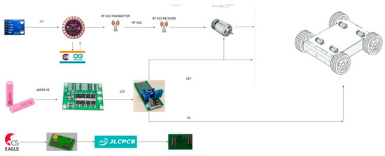
Figure 4.
Robotic chassis subsystem.
The microcontroller monitors the movements of the user’s hand by reading the two axes (x-y) of an analog gyroscope (GY-61). By implementing the necessary logic in the downloaded firmware, the movement direction is decided. Following that, a set of logic levels driving a dual half bridge is outputted on the pins of the microcontroller. These signals must be processed appropriately and sent through wireless communication modules, so that the aforementioned scheme consisting of the encoder and the RF433MHz transmitter is activated properly (Figure 5).
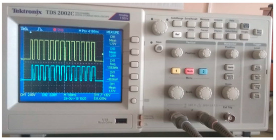
Figure 5.
Modulated RF433 transmitter and receiver signa.
On the receiving end, a wireless receiver retrieves through a decoder the motor driver signals. In particular an L293D digital IC is selected as a motor driver taking into consideration the power requirements of the motors and the cost of the driver itself. In this way, the hand rotation is finally translated into forward–backward or turning commands.
For the whole system power requirements, we provide a first stage of 12-volt BMS output to power the highest voltage elements such as the dc motors and then we utilize voltage regulators to provide secondary power level connections such as the standard 5-volt output to power microelectronic components and processors.
We connect three cells of 3.7-volt nominal voltage in series for a nominal 11.4-volt output before the BMS step UP/DOWN stages. For a 0.5 C of 1300 mA as shown in the above table discharge current, we aim to provide an amperage of 2.6 amperes at low stress connecting two batteries in parallel for a total of six cells. If we take into account the max discharge rate of 5200 mA at an ambient temperature of 25 °C, we can discharge temporarily about 10 amperes without damaging the batteries if we had no protection circuits.
According to usage, the 5200 mAh battery can last, using either the arm or the chassis subsystem at each time, for two hours with a peak amperage 3 amperes.
2.2. Robotic Arm Manipulator
An articulated robot [15] arm is placed on top of the vehicle so as to mimic human like operations. This arm needs to be:
- cost-effective, especially when compared with industrial off-the-self solutions
- easy to use by paramedics with little to no knowledge of electronic equipment handling
- lightweight in order to lower the power and torque requirements of the system
- all in all, easy to produce and program
The aim is to make it a system able to meet efficiently the requirements of the various use cases and challenges faced daily in the context of a smart hospital.
The designed arm manipulator consists of a 5-axis main part plus a 1-axis gripper with a decided length of 50 and 15 cm respectively so as to provide it with the ability to reach and pick items from its surroundings in an easy way facilitated by the selected high torque motors (able to lift the arm’s weight and maximum payload of half a kilogram at 65 cm length which requires 0.5 kg × 65 cm about 30 kg/cm maximum torque for the load only). The precision requirement is relaxed since the pick and place tasks to be performed refer rather to blunt objects of large dimensions than ones with micrometer precision such as those that characterize factory automation robots. Our proof of concept design has even less accuracy of about 3–5 cm as the focus lies in the embedded system of the controller and motion reproduction software and the mechanical design consistency is a future work issue. The accuracy improves with smoother user motion movements and a large margin for better operation exists in both mechanical and software changes.
The aim is that the robotic arm be directly controlled by an operator and not perform automated repetitive tasks so that every action is always being supervised. In a healthcare environment where human and robots should co-exist, a certain requirement is to avoid interactions which could lead to possible accidents. Such high-risk tasks are the automated movements, such as the case is with a low cost system without feedback [16].
Especially the grabbing function needs to be capable of applying to a variety of different tools and equipment of generic shape which need to be transferred or disposed of. This leads to the benefits of low precision requirement, thus avoiding the cost of having to design a number of different grippers suitable for different shapes and sizes. As a matter of fact, the accuracy of an industrial robot tends to be on the order of micrometers therefore requiring additional expenses for provision of low speed precision gearboxes and sophisticated stepper motors. On the contrary, in our case, grasping the generic form of an item and pushing it in a cart alleviates us from the need of employing far expensive parts as would be the case if millimeter accuracy was needed. A first version of the gripper is a mechanically flexible 3-finger endpoint which can change the shape of its fingers responding accordingly to the applied pressure. This is achieved by using flexible and elastic plastic as a material and smart geometry. In that way, the robotic arm’s fingers can hug the item and hold it in place if the proper tension is applied.
As far as the cost side of the arm part is concerned, a custom-made arm like the one in our case reduces the price from a hundred thousand euros to only two thousand euros. The first implemented version, consists of a 3D printed lightweight frame which is designed in Autodesk Fusion 360 using simple solid shapes and putting holes for the shafts and screws and sized properly to withstand the weight of itself as well as of its load, with the total weight of the arm being 830 g plus 305 g with the five motors mounted and 127 g for the griper. The plastic body and the ability to 3D print these design (Figure 6) files offer several advantages, as we sliced each part and printed it in our 3D printer setup with the integration of Autodesk Fusion and the printing tool chain. The manufacturing of such parts can not only be made at low cost for even low volumes but also be distributed directly to anyone interested.
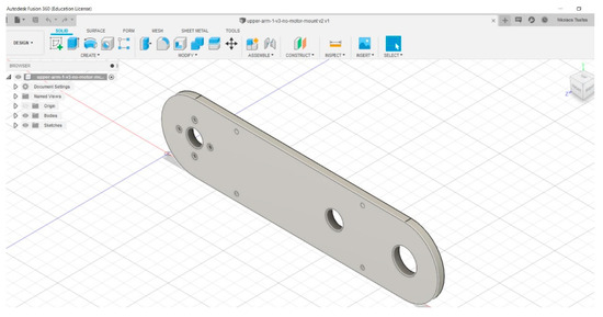
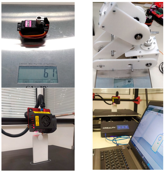
Figure 6.
3D printed parts of the arm manipulator (process and weight).
This system (Figure 7) allows for the handling of hazardous materials which are not safe for human contact reducing the risks that workers take by disposing them. In addition, patients in rooms where human presence is not allowed can be benefitted, in the sense that their environment is kept sterile and contact between nursing stuff and the hospitalized persons is avoided. In this way, infectious diseases do not spread, and internally hospital-acquired infections are reduced.
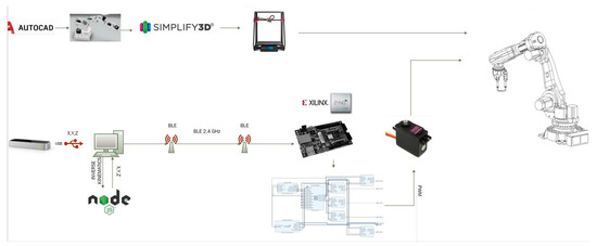
Figure 7.
Robotic arm subsystem.
2.3. Leap Motion Sensor
The Leap motion [17] is a controller device running on a host computer that can capture movements from hands and fingers in 3D space using a set of two monochrome cameras and three infrared LED sensors. The operator’s arm should lie approximately half a cubic meter above the device (Figure 8) so that the device produces a set of data associated with the position and movement speed of fixed points on the arm, palm and finger [18,19].
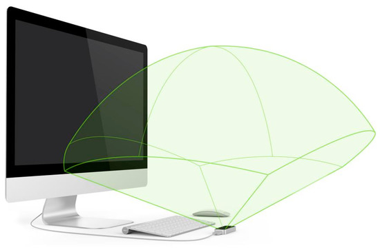
Figure 8.
Leap Motion Sensor space.
This device is similar to Kinect, but its specific capabilities make it a better choice for our application. Compared to Microsoft Kinect [20], Leap’s interaction zone is limited to a cubic meter space in front of the sensors and compared to the Kinect’s interaction zone is much broader, in the order of a room. Nevertheless, it produces data which are characterized of better accuracy due to its number of sensors.
Furthermore, it is not necessary to employ image processing algorithms so as to extract the relevant points, and gestures performed. The API accompanying the sensor takes up the complex math part, while the Leap Motion Controller applies advanced algorithms to the raw sensor data. Additionally, the Leap SDK (Figure 9) provides built-in classes representing real-world object seen by the controller. The basic data contain objects like hands and pointables (fingers and tools), described by features directly related to real attributes. Hand is an object representing a regular human hand. It contains Fingers, and is described by three dimensional values, e.g., position of center of hand, normal vector, and direction vector (pointing from the center to the end of fingers) [21].
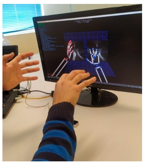
Figure 9.
Leap Motion diagnostic tool viewer.
The programming interface of the Leap Motion sensor offers the ability to program it in a variety of programming languages such as C Sharp, JavaScript, C++, etc., while offering an abstraction level through its built-in functions. Also, a viewer is available to depict the rendered model of the arm and palm in 3D space as perceived by the computer. This gives an optical feedback to the user making it easier to plan his moves and coordinate both his and the robot’s movement, the starting position, and deviations [22].
Thus, we do not need to implement graphic processing algorithms or even calculate the different body part positions since most of the useful information is readily available to us by the Leap libraries. This adds the benefit of having a tested working framework which can ensure the correct estimation of the user’s movements. We can focus on this way in the development of more useful tasks, such as recognizing problematic cases and tackling with scenarios like limiting the model’s speed if the operator moves his hand too fast or exceeds the maximum range of motion.
The use of such a virtual reality scheme allows for a remote operation of the robot arm without the need for special equipment [23].This can compensate for the sensor tradeoff where a cheap optical sensor replaces expensive schemes of wearable mechanical tactile switches and joysticks [24].
The design of this device gives the ability to integrate sensor capabilities without having to use other alternatives such as physical contact devices which need a high effort to take approval for contact with humans. It is evident that less equipment means both lower cost of the total system and easier integration in a constrained environment such as a hospital.
Furthermore, the fact that, in this way, the movement of a human’s arm can be readily imitated without any difficulty gives a clear advantage in contrast to the most common solution of joysticks which require months of formal training. This includes practice and skills that need months to even reach the degree of sensitivity that our approach provides from an early try.
2.4. Zynq APSoC Controller
This low-cost, system requires an innovative approach for the design of the system controller which is integrated into the robotic system. The chosen device is an all-programmable embedded arm processor along with an integrated Xilinx reconfigurable hardware device, i.e., the Zynq System on Chip (Cora Z-7010) [2] shown in Figure 10. This chip comes in a module-form board combined with embedded peripherals such as wired communication protocol controllers, wireless connectivity, video/audio decoding circuitry, and power management ICs [24].
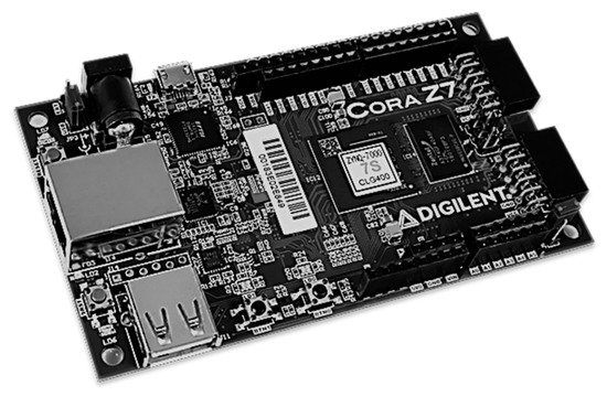
Figure 10.
ZYNQ Z7-7010 Dual Core ARM-FPGA SoC.
Compared to other approaches that are based exclusively on embedded processors and external motor driving circuits, the integration of reconfigurable hardware and advanced processing cores, like the dual core ARM Cortex-A, on the same chip allows for faster integration, higher logic speeds, as well as customized and more precise control while reducing the total circuit count.
In order to meet the system needs, the chosen afore-described approach provides a low-cost solution since various circuits can be integrated into the existing field-programmable gate array (FPGA). Different types of motors can be driven directly by the hardware part of the chip with the help of precise timing signals and fast parallel monitoring for implementing a close loop control facilitated by the software part of the chip (the ARM). This provides us with the capability to develop fully custom motor driver logic without the need for uniformity, using different size and even type of motor in each part. For instance, higher torque requirements can be fulfilled by geared dc motors with position encoders or stepper motors with step count or error code feedback while the rest motors can be all-in-one servo motors.
These can be complemented by parallelism of movements provided from the FPGA [25] as well as a larger set of control ports for supporting a wider number of motors to control both the chassis and the arm or a rotating camera which can be instantiated on the hardware and its large number of pins.
The embedded dual core ARM Cortex-A processor can be used to take care of the communication of the system with the remote controllers and the host computer. More complicated tasks can be implemented in the processor, including path finding algorithms which require a number of sensor reads and mathematical computations, self-checking and automatic calibration sequences for the right coordination of user device movements as well as video compression and image processing. Also, the availability of a multi-core scheme allows for using the second core as a supervisor for critical tasks and interrupt handling in error states.
All these give the ability to reduce the total size of the mobile system, its power requirements, and both initial cost as well as costs related to application development and time to market. In Table 1 which compares our approach (ZYNQ Cora Z7) with a representative existing case, the difference in size and cost between an industrial arm controller (KRC4) [26] and the proposed design is shown. This result is somehow expected, since in off-the-self products call for bulky older technology controllers based on electronics such as PLC that increase the total size and of course the price.

Table 1.
Comparison between our approach and an industrial arm controller.
Also, a main advantage of the selected all-programmable chips is the ability to not only receive updates but more importantly extend the physical capabilities of the whole system. This includes the ability of easily implementing new protocols and making changes in digital circuits achieving higher throughput. These changes can be implemented with the same ease as a firmware over the air update, which makes the deployment of updated versions of the system especially in its early revisions quite appealing in a testing site such as the smart hospital.
3. Implementation Description
3.1. Software
The design and development of the software is performed in JavaScript and it uses leap’s motion library (leap.js) and the Johnny-Five framework [27]. The developed software takes up the role of calling the functions to capture the movements from hands and fingers in 3D space from the leap motion device (X, Y, Z) and sends the data directly to the JavaScript program running on the host PC via USB.
The next step is to translate the final and current position difference coordinates to rotation and speed parameters to drive the (robotic arm’s) actuators. The data are stored in local variables and the main program is running on host PC with the help of Node.js. With the use of the Math Library, the main program calculates via the Inverse Kinematics equations the position or speed changes along with the type of movement of each observation point (Figure 11) on the robotic arm [28].
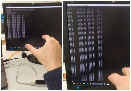
Figure 11.
Leap software’s distance of shoulder, elbow, claw points from sensor.
The data acquisition as well as their processing and transmission are made in distinct steps of the main program loop that coordinates the sensors, the algorithms running on computer, the hardware-software coprocessors and the mechanical components in a closed loop. The algorithm’s steps are shown in Figure 12.
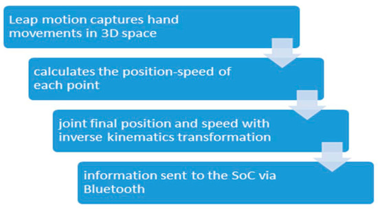
Figure 12.
Algorithm Steps of main program loop.
By the time that the calculation is finished we use Johnny- Five framework to calculate the PWM parameters that are to be sent to the SoC controlling the robotic arm. The communication part between the host PC and the SoC (Zynq Cora Z7) is achieved with the use of PC’s Bluetooth port and a BLE module (cc2541) at the robotic platform, acting as a peripheral of the Zynq module, that transfers the data from the UART0 port directly to the ARM A9 microprocessor at a range of 20 m with the current implementation and the ability to expand it with a dongle rated for 80 m which is the limiting factor for the operating range.
The second stage of Software is the Embedded Software part developed in embedded C language running on the ARM microprocessor. This part is a custom implementation of Firmata’s protocol for realizing the communication between microcontrollers, that is, receiving the data from the UART0 since the UART1 port on ZYNQ is reserved for receiving data from the micro-USB port. After the ARM microprocessor receives the data it assigns to the PWM the motor that it must control. The output of this stage is sent to FPGA, (described in the next section) which, with the help of the customized logic in VHDL, controls the circuits that drive the motors, calculates the duty cycle of the PWM, and supervises the motor to check whether it reaches the desired final position (Figure 13).
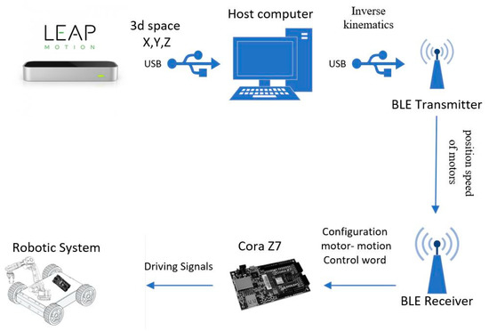
Figure 13.
Communication System Overview.
3.2. Hardware
The control unit of the mobile robotic platform consists of two main parts, a powerful dual core Arm Cortex-A processor and a Xilinx Zynq-7000 series XC7Z010 FPGA. The design of the whole architecture includes the embedding of the communications and supervision functions in the former part of the chip and the signal generation, sampling, as well as any other processing task in the latter one. Also, a customized design of the AXI-4 protocol for the communication between the processing system and the programmable logic is also implemented onto the FPGA part.
The main advantage stemming from the selected system on chip solution is its ability to execute tasks in parallel. Having isolated the connectivity of the robotic platform with the host pc from the actuating functions we remove the bottlenecks in performance. The main loop need not be interrupted to receive data and at the same time different tasks run concurrently passing messages to each other due to the shared memory of the dual core processor. Multi-axis positioning systems also benefit from the ability to receive commands and monitor their status concurrently, resulting in more effective response when demanding real time position changes take place [29]. In contrast to our system on chip option (Figure 10), the use of a single processor simply would not have the resources required, neither the embedded components nor the physical pin connections to directly drive a number of closed loop motor solutions.
Thus, through our approach, the need for external signal decoding circuits and multiplexing is minimized therefore reducing drastically the total latency.
Regarding robotic arm motor control, the FPGA can integrate both driving and monitoring functions as shown in Figure 14c. The high rate and frequency of the timing circuits favors parallel processing so as to achieve real time refinement of the closed loop control parameters.
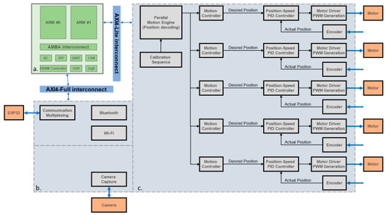
Figure 14.
Hardware IP Controller. (a). Embedded dual core processor, (b). Communication hardware accelerator, (c). Hardware motion engine.
Positional encoders such as magnetic hall effect sensors can be added in cheaper motors. This solution has been adopted in our case and has been implemented by creating counters in hardware which monitor pins set as inputs and increasing their value for each encoder step to one direction and reducing their countfor each step to the other side. This is complemented by debouncing logic and an interface to the processor. Each motor’s control hardware IP (intellectual property) in the FPGA has a set of control registers for storing the desired position and mode of operation, as well as status registers which show the current position. These circuits are all memory addressed and compatible with the ARM AXI4-Lite protocol. In contrast, a solution based solely on a processor has to sequentially check the readings of each motor sensor and perform its feedback loop code, while our design checks internally in its gates if the movement has been completed, providing an abstraction in its operation.
Another advantage is the ability to change the motion profile of each motor as well as develop calibration mechanisms for each load scenario addressing the inertia mismatches. Inside the FPGA, the acceleration and deceleration of the shaft is controlled initially by a default trapezoidal profile. At the same time, the position is monitored, and the speed of the rotation is computed. If the actual speed is less than the predefined one, then another profile is selected through a multiplexer that ramps up the speed at a slower rate and keeps a smaller continuous rotation speed so as to handle torque more efficiently for smaller loads on the motor axis and vice versa.
As an indicative example, a single core μPc needs 3 clock periods to configure the control registers of each motor circuit for a total of 15 periods (5-axis manipulator). On the contrary, our design transfers in 3 periods the total parameters for all circuits to the FPGA. Then, a hardware motion engine decodes this information and configures the 5 subsystems at the same time (3 periods). In this way the total latency is reduced to 6 periods (60% savings) (Figure 15).
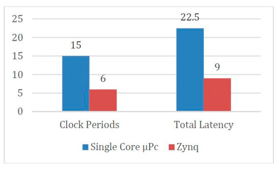
Figure 15.
Comparison between single core processor and MPSoC.
This is better achieved by a custom implementation of the AXI4-Lite protocol of the motion engine IP. With the use of glue logic, the messages received from the processor for the motor positioning in a packaged format are split and sent to the appropriate AXI interfaced motor IP. In this way, with one write command in the outer motion IP, three AXI write operations are performed concurrently in otherwise separately addressable sub-circuits (Figure 16). This provides an immense benefit as each write operation requires several clock cycles, which are all saved.
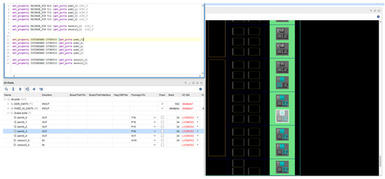
Figure 16.
Implementation environment of Hardware mapping.
4. Future Work
Having created a first showcase version of the total implementation, a number of improvements and additions are in place for the refinement of the existing subsystems and provision of added functionality. A task already in progress regards an embedded USB camera that is to be added directly to the ZYNQ SoC so that an AI algorithm could detect different classes of objects inside the hospital isolated room and return the video feedback to the host pc using WiFi ICs like the popular ESP-32 one for ensuring higher bandwidth. Further improvements to enhance the connectivity of the platform through the WiFi addition which can provide access from any remote location. The various sensor readings as well as the control can be monitored in real time creating a digital representation in the form of a digital twin. In this way, we could be aware of the state, past actions, statistics, and analytics pertaining to the operation of each system part, as well as gain the capability to program tasks more conveniently.
5. Conclusions
In this article, the design and implementation of a mobile robotic assistant for hospital use is presented, and is especially useful in cases of treatment of infectious diseases inside isolated rooms. Providing a solution to such a need requires the integration of different and innovative technologies.
New sensors [30] like the Leap Motion controller can respond to specific demands of this use case, providing tele-operation capabilities which are both non-invasive and user friendly. Actually, the first feedback from a non-trained user, from our lab instead of a paramedic has added to this conclusion with the required training time being less than a week for young adults with tech experience. Other older methods like gloves, joysticks, or Microsoft’s Kinect have been shown to be less appropriate in terms of cost and usability. Also, taking into consideration the need of rapid deployment in times of crisis, as well as cost and integration, a custom design of a robotic arm manipulator has been designed and constructed using modern techniques such as 3D printing.
Mechanical parts and motor actuators have been based on be available off-the self-solutions while also having in mind the accuracy constraints and operational needs of a hospital pick and place system. The presented system developed has proven to be tens of times cheaper than industrial grade approaches, as well as being easier to upgrade and use.
In addition, new more capable coprocessor designs have been employed in order to achieve better performance, power consumption and tighter integration of various subsystems. A combination of software and hardware programmable onto a chip gives the ability to include all kinds of communication, monitoring and actuating functions as well as the freedom to upgrade any part in the future.
Comparing our approach to similar ones the main differences lie in the use of custom parts and controller for the robot as well as a novel operation scheme. No other approach has such a way of handling nor does it come up with a manipulator other than the industrial ones like KUKA and Universal Robots. For this reason, the advantages are the low cost and ease of reproduction by anyone having a 3D printer and knowledge of embedded at his lab outside of factories. On the other hand, comparing to others, we have limited accuracy, operating time, and range, as discussed above, as our approach is a proof of concept for the low cost teleoperated hospital assistant which is not yet accepted as a standard medical equipment.
In this paper, the implementation of the system has been thoroughly discussed from an embedded system perspective integrating software and hardware techniques. As for the functions, this robotic system implements this robotic system’s main task is to mimic human movements, i.e., the real time transfer of the sensory input to the arm in the form of the users movements. As a proof of concept of our idea, the jobs performed are mainly dictated by the user and his hand moves. This constitutes a feedforward system as it does not yet implement autonomous functions by backward propagation of the sensor input to the controller logic. This is of course the next step of our research after the system has taken a solid form. Some examples are medication transfer to and from hospital rooms as well as area surveillance with direct video feedback and immediate intervention in simple pick and place tasks near the patient.
In conclusion, this article presents a really cost efficient and easily upgradable robotic system.
Author Contributions
In this article each individual contributor provided his expertise according to their research interests and background. C.P. led the embedded software and motion sensor code development and contributed to the printing of the 3d parts needed. N.T. oversaw the hardware implementation of the fpga and interconnection with the processor as well as the printed circuit boards used and power electronics. M.B. had the role of supervisor as the professor overseeing this shared work and helped with his advice and directions. All authors have read and agreed to the published version of the manuscript
Funding
This research has been funded by the DEEP-EVIoT—Deep embedded vision using sparse convolutional neural networks project (MIS 5038640). Implemented under the Action for the Strategic Development on the Research and Technological Sector, co-financed by, national funds through the Operational program of Western Greece 2014–2020 and European Union funds (European Regional Development Fund) and by the European Regional Development Fund of the European Union and Greek national funds through the Operational Program Competitiveness, Entrepreneurship and Innovation, under the call RESEARCH-CREATE-INNOVATE (project code:T1EDK-03832).
Conflicts of Interest
The authors declare no conflict of interest, there is no connection between Industrial Systems Institute (ISI) RC ATHENA and the subject of this manuscript.
References
- Paparizos, C.; Tsafas, N.; Birbas, M. Design and Implementation of an APSoC-Based Robotic System with Motion Tracking Teleoperation. In Proceedings of the 2019 8th International Conference on Modern Circuits and Systems Technologies (MOCAST), Thessaloniki, Greece, 13–15 May 2019; pp. 1–4. [Google Scholar] [CrossRef]
- Robots, Intelligent Medical Care Respond to Coronavirus Outbreak. Available online: https://www.chinadaily.com.cn/a/202002/02/WS5e366cb4a3101282172742b8.html (accessed on 2 February 2020).
- “LBR Med—Robotics in Healthcare|KUKA AG”, KUKA AG. Available online: https://www.kuka.com/en-my/industries/health-care/kuka-medical-robotics/lbr-med?fbclid=IwAR22K_nZCslhOrCyGiR5tR4ySI9VTwH9mlKFed4Y4fxX4W_1bFYnoymj6Xs (accessed on 27 January 2020).
- Ahn, H.S.; Lee, M.H.; MacDonald, B.A. Healthcare robot systems for a hospital environment: CareBot and ReceptionBot. In Proceedings of the 2015 24th IEEE International Symposium on Robot and Human Interactive Communication (RO-MAN), Kobe, Japan, 31 August–4 September 2015; pp. 571–576. [Google Scholar] [CrossRef]
- Garmann-Johnsen, N.; Mettler, T.; Sprenger, M. Service Robotics in Healthcare: A Perspective for Information Systems Researchers? In Proceedings of the Thirty Fifth International Conference on Information Systems, Auckland, New Zealand, 14–17 December 2014. [Google Scholar]
- Chen, C.; Chen, L.; Zhou, X.; Yan, W. Controlling a robot using leap motion. In Proceedings of the 2017 IEEE 2nd International Conference on Robotics and Automation Engineering (ICRAE), Shanghai, China, 29–31 December 2017; pp. 48–51. [Google Scholar] [CrossRef]
- Maximilian, W.; Dennis, A.; Peter, H. Gamepad Control for Industrial Robots—New Ideas for the Improvement of Existing Control Devices. In Proceedings of the 13th International Conference on Informatics in Control, Automation and Robotics, Lisbon, Portugal, 29–31 July 2016; SciTePress: Setúbal, Portuga; pp. 368–373. [Google Scholar] [CrossRef]
- “Industrial robot|KUKA AG”, KUKA AG. Available online: https://www.kuka.com/en-my/products/robotics-systems/industrial-robots/ (accessed on 26 January 2019).
- Bruce, A.; Nourbakhsh, I.; Simmons, R. The role of expressiveness and attention in human-robot interaction. In Proceedings of the 2002 IEEE International Conference on Robotics and Automation, Washington, DC, USA, 11–15 May 2002; Volume 4, pp. 4138–4142. [Google Scholar]
- Penteridis, L.; D’Onofrio, G.; Sancarlo, D.; Giuliani, F.; Ricciardi, F.; Cavallo, F.; Greco, A.; Trochidis, I.; Gkiokas, A. Robotic and Sensor Technologies for Mobility in Older People. Rejuvenation Res. 2017, 25, 401–410. [Google Scholar] [CrossRef] [PubMed]
- Zynq 7000 Product Selection Guide. 2019. Available online: https://www.xilinx.com/support/documentation/selection-guides/zynq-7000-product-selection-guide.pdf (accessed on 26 January 2019).
- Jin, J.; Chung, W. Obstacle Avoidance of Two-Wheel Differential Robots Considering the Uncertainty of Robot Motion on the Basis of Encoder Odometry Information. Sensors 2019, 19, 289. [Google Scholar] [CrossRef] [PubMed]
- Mukherjee, U.K.; Sinha, K.K. Robot-assisted surgical care delivery at a hospital: Policies for maximizing clinical outcome benefits and minimizing costs. J. Oper. Manag. 2020, 66, 227–256. [Google Scholar] [CrossRef]
- Niku, S. Introduction to Robotics; John Wiley & Sons: New York, NY, USA, 2011; ISBN-10: 0130613096. [Google Scholar]
- Moreno, J.; Clotet, E.; Tresanchez, M.; Martínez, D.; Casanovas, J.; Palacín, J. Measurement of Vibrations in Two Tower-Typed Assistant Personal Robot Implementations with and without a Passive Suspension System. Sensors 2017, 17, 1122. [Google Scholar] [CrossRef] [PubMed]
- Leap Motion, En. wikipedia.org. 2010. Available online: https://en.wikipedia.org/wiki/Leap_Motion (accessed on 27 January 2019).
- Tapus, A.; Mataric, M.J.; Scassellati, B. Socially assistive robotics [grand challenges of robotics]. IEEE Robot. Autom. Mag. 2007, 14, 35–42. [Google Scholar] [CrossRef]
- Škraba, A.; Koložvari, A.; Kofjač, D.; Stojanović, R. Wheelchair maneuvering using leap motion controller and cloud based speech control: Prototype realization. In Proceedings of the 2015 4th Mediterranean Conference on Embedded Computing (MECO), Budva, Montenegro, 14–18 June 2015; pp. 391–394. [Google Scholar] [CrossRef]
- Kinect, En. wikipedia.org. Available online: https://en.wikipedia.org/wiki/Kinect (accessed on 27 January 2019).
- PilSeong, J.; Yang-Hyun, C. Design and Implementation of Finger Language Translation System using Raspberry Pi and Leap Motion. J. Korea Inst. Inf. Commun. Eng. 2015, 19, 2006–2013. [Google Scholar] [CrossRef]
- Wang, Y.T.; Yuan, L.; Cai, J.J.; Wang, H.; Zhang, Q. Interaction design of gesture control for DMS multi-channel system. In Proceedings of the 2017 IEEE 9th International Conference on Communication Software and Networks (ICCSN), Guangzhou, China, 6–8 May 2017; pp. 1524–1528. [Google Scholar] [CrossRef]
- Pititeeraphab, Y.; Choitkunnan, P.; Thongpance, N.; Kullathum, K.; Pintavirooj, C. Robot-arm control system using LEAP motion controller. In Proceedings of the 2016 International Conference on Biomedical Engineering (BME-HUST), Hanoi, Vietnam, 5–6 October 2016; pp. 109–112. [Google Scholar]
- Mikolajczyk, T. Control System for Industrial Robot Equipped with Tool for Advanced Task. Manuf. Appl. Mech. Mater. 2015, 783, 105–113. [Google Scholar] [CrossRef]
- Kung, Y.-S.; Shu, G.-S. Development of a FPGA-based motion control IC for robot arm. In Proceedings of the 2005 IEEE International Conference on Industrial Technology, Hong Kong, China, 14–17 December 2005; pp. 1397–1402. [Google Scholar] [CrossRef]
- Michael, P.A.; Devarajan, N. FPGA Implementation of Multilevel Space Vector PWM Algorithms. Int. J. Eng. Technol. 2009, 1, 208–212. [Google Scholar] [CrossRef][Green Version]
- KUKAKRC4. Available online: https://www.kuka.com/ende/products/robotsystems/robotcontrollers/kr%C2%A0c4 (accessed on 18 March 2019).
- Perch, K. Working with Johhny-Five, 1st ed.; Packt Publishing: Birmingham, UK, 25 November 2015; pp. 9–12, Chapter 2; ISBN 978-1785883347. [Google Scholar]
- Kebir, S.T.; Bouhedda, M.; Mekaoui, S.; Guesmi, M.; Douakh, A. Gesture control of mobile robot based arduino microcontroller. In Proceedings of the 2016 IEEE 8th International Conference on Modelling, Identification and Control (ICMIC), Algiers, Algeria, 15–17 November 2016; pp. 1081–1085. [Google Scholar]
- Sathyan, A.; Milivojevic, N.; Lee, Y.; Krishnamurthy, M.; Emadi, A. An FPGA-Based Novel Digital PWM Control Scheme for BLDC Motor Drives. IEEE Trans. Ind. Electron. 2009, 56, 3040–3049. [Google Scholar] [CrossRef]
- Shabana, N.; Velmathi, G. Advanced Tele-surgery with IoT Approach. In Intelligent Embedded Systems; Thalmann, D., Subhashini, N., Mohanaprasad, K., Murugan, M., Eds.; Lecture Notes in Electrical Engineering; Springer: Singapore, 2018; Volume 492. [Google Scholar]


© 2020 by the authors. Licensee MDPI, Basel, Switzerland. This article is an open access article distributed under the terms and conditions of the Creative Commons Attribution (CC BY) license (http://creativecommons.org/licenses/by/4.0/).