1. Introduction
With the increased need for stable communications with and between high-mobility UEs, such as V2V, V2X, LEO satellites, and highly mobile IoT devices, waveforms and modulation systems capable of demodulating data in the presence of Doppler shift are required [
1]. Existing implementations of OFDM exhibit performance deterioration in high-mobility scenarios [
2,
3,
4,
5]. To address this issue, different OFDM-based systems have been proposed, simulated, and tested [
6,
7,
8], with the main goal of improving communication performance in high-mobility scenarios. Doppler-assisted channel estimation for high-mobility communication using classical OFDM was also explored in many works [
9,
10].
One of the multicarrier modulation formats designed for communication with high-mobility UEs, first published by R.Hadani et al. [
11] in 2017, is OTFS. This format was initially based on OFDM, with an additional pre/post-modulator that employs Heisenberg and Wigner transforms to achieve frequency-domain orthogonality. With the introduction of the DZT into the signal processing pipeline [
12,
13,
14], the implementation of OTFS became simpler. IDZT directly converts DD-domain symbols into the time-domain transmit signal, while the corresponding inverse operation at the receiver directly recovers the DD-domain symbols, thereby replacing the separate IFFT-based/Heisenberg modulation and Wigner/FFT-based demodulation stages with a unified transform pair. OTFS is also being proposed as part of 6G [
15,
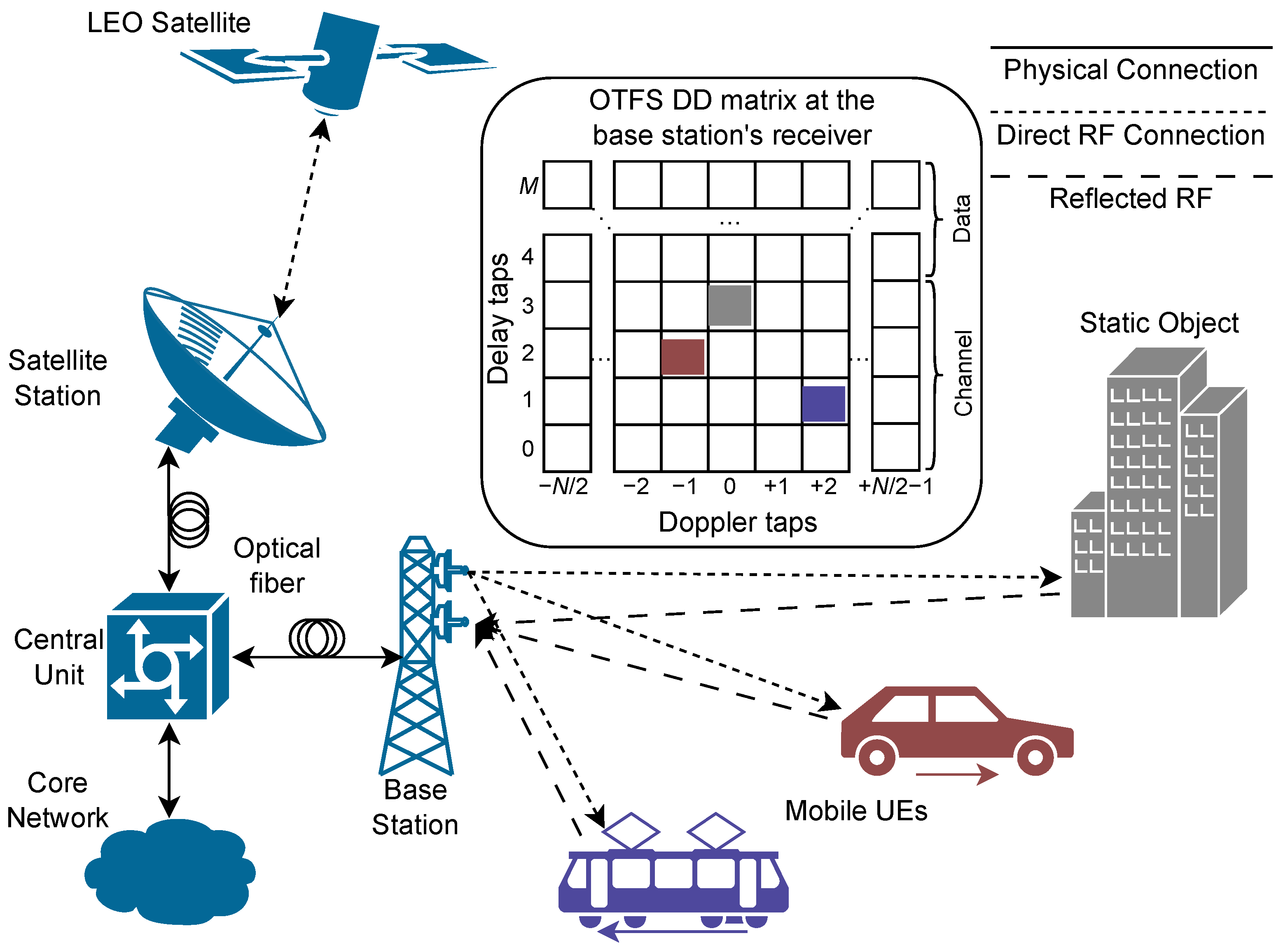
16] with NTN integration in mind. In OTFS, data are multiplexed in the DD domain, which facilitates the estimation of the delay and Doppler of received signal reflections, and thus enables the detection of target distance and velocity. The OTFS DD domain matrix is shown in
Figure 1, where reflections from static and mobile objects are present at the receiving base station, which performs the sensing function. These marked DD cells have their own delay and Doppler tap values, which correspond to the reflected pilot pulses transmitted by the sensing base station.
To reduce costs associated with the introduction of next-generation communication systems, e.g., 6G, existing base stations with RAUs can be connected to the CU, located tens of kilometers away. A CRAN scenario where the optical link is employed to connect the CU to base and satellite stations is depicted in
Figure 1.
As the generated RF signal must be transmitted over multiple kilometers through the fiber, ARoF-capable waveforms should be employed. Existing research shows that OTFS can be transmitted using an ARoF setup [
17]. Special types of OTFS [
18,
19,
20] are intended to deal with OWC environments, such as VLC, where the envelope of the RF signal should be real and positive due to the employment of intensity-modulation and direct detection.
SDR enables fast prototyping of radio communication systems and is a significantly cheaper alternative to arbitrary waveform generators. Multiple practical implementations of OTFS systems on SDR exist [
20,
21,
22], with the first implementation conducted by T.Thaj and E.Vitebro in 2019 [
23]. OTFS ISAC implementations on SDRs also exist [
24,
25,
26,
27,
28], and the number of reported successful implementations is increasing each year.
Most of the mentioned implementations use direct wireless analog transmission from the SDR [
21,
22,
23,
24,
25,
26,
27,
28] or employ arbitrary waveform generators and digital oscilloscopes to generate and receive OTFS waveforms [
17,
29,
30]. In this paper, SDR hardware is employed in the prototyping of a real-time communication system in ARoF with wireless RF communication. OTFS system on SDR is implemented in the ARoF setup with an 800 m long SMF span. This paper provides a full description of the optical setup in use, which is comprised of the minimum number of hardware components required to achieve an ARoF link between the SDR’s input and output ports. In comparison with other implementations of OTFS, which are primarily meant for V2X or vehicle-to-base station scenarios for high-mobility communications [
26,
27,
31], this study addresses very low velocity < 1 km/h detection of a moving object at the cost of distance resolution. The sensing part of this OTFS ISAC system estimates the velocity of an object that reflects the RF OTFS signal in real time, essentially performing the role of a monostatic radar for object velocity and movement direction detection. It is worth noting that the use of ARoF not only increases the maximum allowed distance between the antennas and the CU, but can also enable distributed optical fiber sensing capabilities [
32] in addition to the implemented ISAC.
This work is divided into the following sections:
Section 2 describes an SDR implementation of an OTFS system, while
Section 3 provides the description of an optical setup used in the experiments. Results from the conducted experiments are available in
Section 4, with discussion and conclusions in
Section 5 and
Section 6, respectively.
2. Software-Defined Radio Implementation of an OTFS System
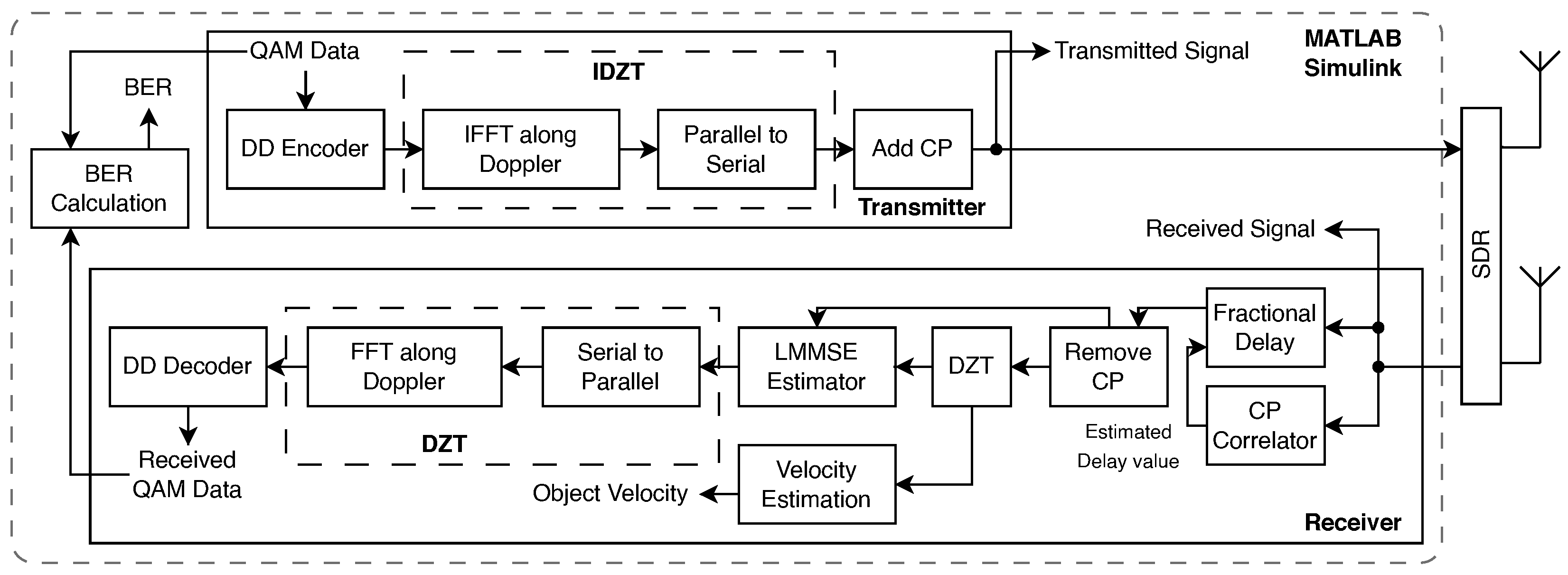
A real-time OTFS communication system for ISAC validation was implemented in MATLAB Simulink R2025a running on a PC connected to the USRP B210 (Ettus Research, Austin, TX, USA) SDR. The block diagram of the implemented OTFS transceiver Simulink model is presented in
Figure 2.
First, at the transmitter side, QAM data is encoded in the DD domain—
matrix, where
N is the number of time slots (Doppler bins) and
M is the number of subcarriers (delay bins). Then IDZT is applied to transform the DD domain into the time domain for transmission. IDZT can be split into two major steps: application of IFFT and P/S conversion. First, QAM data
in the DD domain is moved to the DT domain via the application of IFFT along Doppler dimension:
where
is an
DD domain matrix with QAM encoded data,
is a DT domain matrix, before P/S conversion into the time domain, which is necessary for transmission into a real-world communication channel. After the IFFT step, column-by-column, or in this case, column is a sub-carrier, P/S conversion is applied to get a time domain signal vector
using
from Formula (
1):
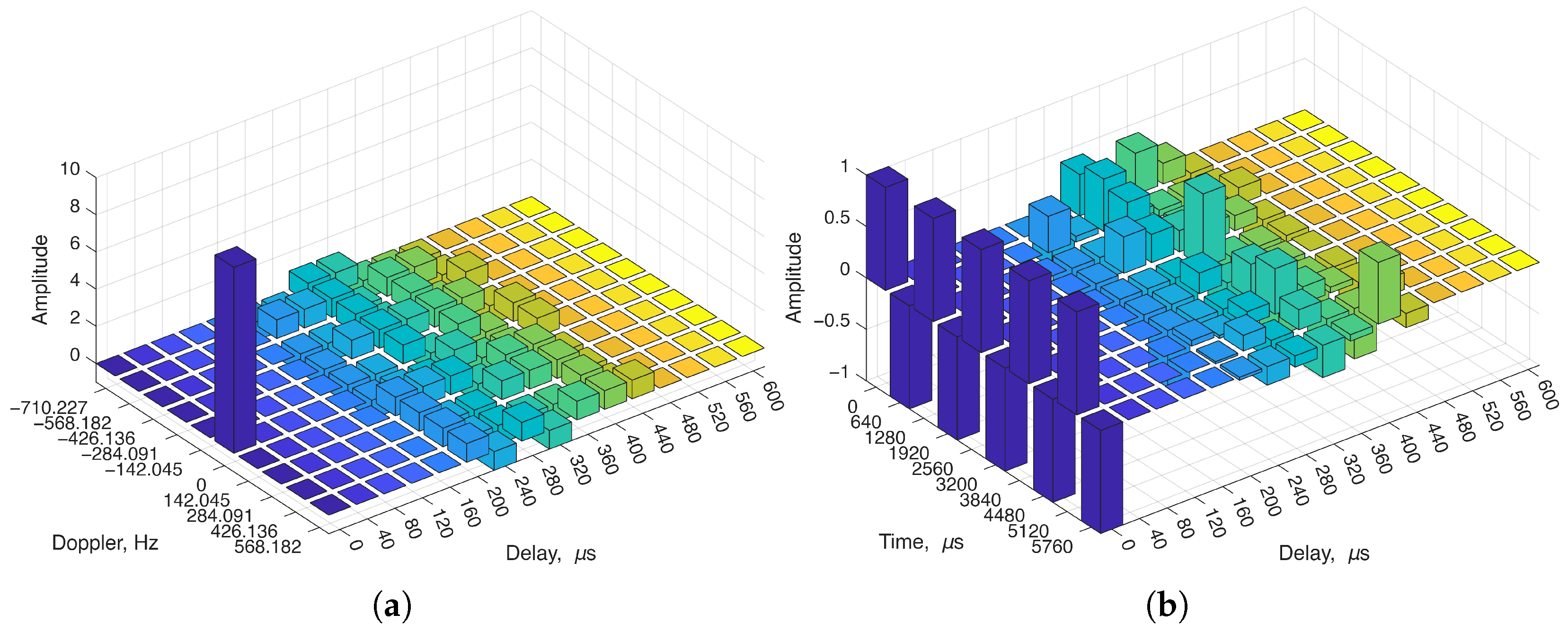
The positions of data with ZP and the pilot in the DD and DT domains before and after the IFFT, applied by (
1), are shown in
Figure 3.
After the P/S conversion, a CP is added to enable synchronization at the receiver side:
where
is a CP length in samples, and
is a time domain signal vector with appended CP in the front of the signal
.
Before the transmission, up-sampling of a discrete signal
is done by the repetition of each sample
times:
where
is an up-sampled discrete signal vector that will be sent to the SDR for transmission.
On the receiver side, the received signal is split between the CP correlator and the fractional delay blocks. CP correlation is needed to estimate the fractional delay of the received signal, so that the OTFS frame is passed to the rest of the system at the right starting sample. If the starting sample is delayed by a value outside the channel estimation window, demodulation will yield errors in the received data. In the radar system, this sudden sample delay will show as a non-zero distance if the transmitted signal is synchronized to the hardware propagation time delay.
After synchronization via CP correlation, the CP (the first
samples) is removed from the time-domain signal, and down-sampling by an
r order is performed. The received signal will be altered by delay and Doppler effects, which can be expressed by the conventional multi-path Doppler channel model:
where
K is the number of channel paths, each characterized by a complex gain
, delay
, and Doppler shift
.
B denotes the system bandwidth,
is the modulo-
operator, and
is a serial discrete signal of size
.
Both signals, before and after the first DZT, are used in the LMMSE channel estimation. DZT, similarly to the IDZT used in the transmitter, can be split into S/P and FFT parts, expressed by Formulas (
6) and (
7), respectively:
where
is a DT domain matrix of size
after S/P and before FFT along the time dimension:
where
is a DD domain matrix after application of FFT in DZT.
Before LMMSE is performed, the channel in the DD domain from the first DZT is normalized and then used for object velocity estimation. The equalized signal from the LMMSE estimator is then converted to the DD domain via a second DZT using the previously defined Formulas (
6) and (
7). After DZT, QAM data are decoded, and the resulting binary data are used to calculate BER, which is used in the system’s performance evaluation.
Parameters of the implemented OTFS communication system on the USRP B210 SDR are shown in
Table 1.
The OTFS signal bandwidth F and numbers of bins were chosen specifically to achieve velocity estimation resolution , because movement of a large metal plate used as a signal reflector at such a velocity can be performed under laboratory conditions. Given the limitations of the experimental setup and OTFS signal parameters, the distance cannot be measured without special delays, as a minimum distance of to the object is required to measure the single-tap delay of the pilot signal.
3. Experimental Setup
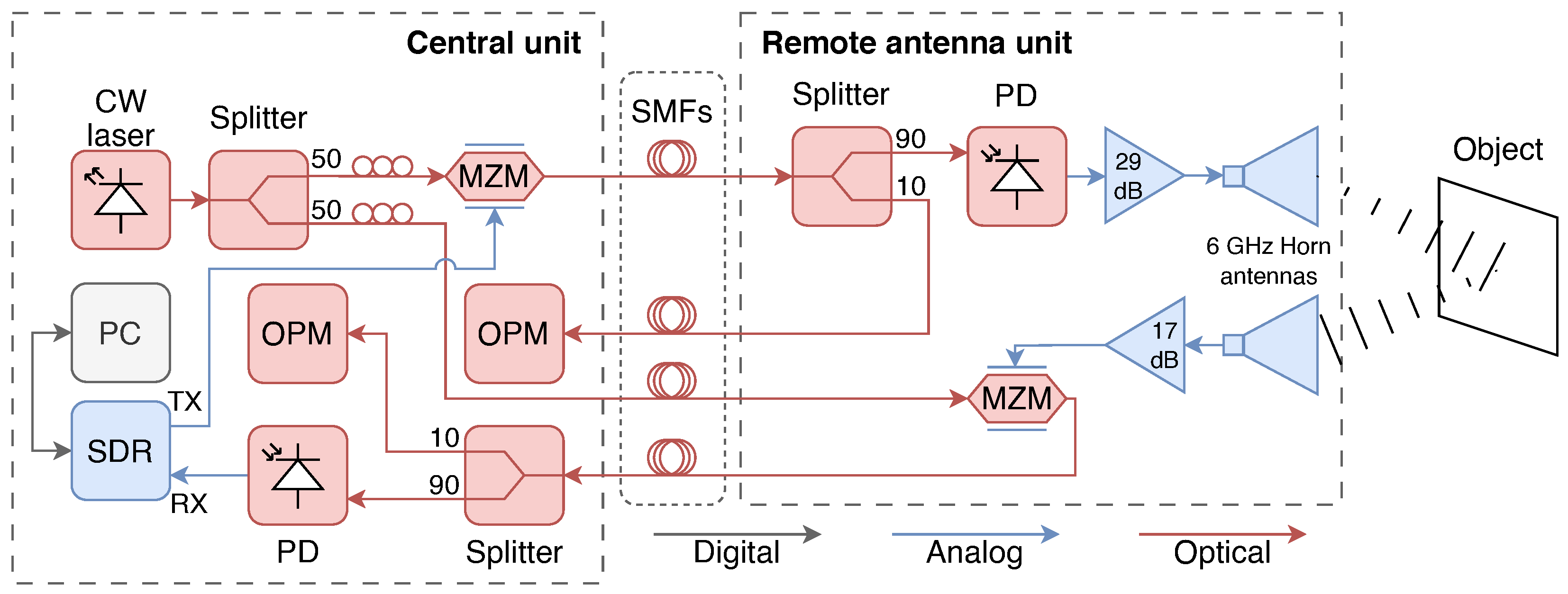
The experimental setup consists of the CU and the RAU, connected by 400 m long SMF spans. The OTFS waveform was generated by the USRP B210 SDR using parameters from
Table 1. The “TX” port of the SDR, with a maximum power of
, was connected to the MX-LN-40 MZM (Exail Technologies, Paris, France), which features a 40 GHz bandwidth, a 20 dB extinction ratio, and a 3.5 dB insertion loss. The optical carrier was generated by the DX-4 CW laser (ID Photonics, Neubiberg, Germany), which has a line width of 25 kHz. The wavelength of the optical carrier was 1550 nm. The optical power of the carrier +2.4 dBm was split using a 50/50 optical power splitter and sent through the polarization controllers.
The optical output of the MZM was connected to the KG-PT-10G-SM-FA InGaAs/InP planar structure PIN PD (Conquer, Beijing, China) through a 90/10 optical power splitter for remote power monitoring purposes. The PD features a 10 GHz bandwidth, a dark current of 10 nA, and a responsivity of . The OPM was used to maintain an optical power of on the PD, as the PD’s saturation limit is . The PD’s RF output was connected to the SHF 810 broadband RF amplifier (SHF Communication Technologies AG, Berlin, Germany) with 29 of gain and a 38 GHz bandwidth. The amplified signal was fed into the WR-159 horn antenna (Pasternack, Irvine, CA, USA), which has a gain of 20 and a frequency range of 4.9–7.05 GHz.
The same antenna model was used at the receiving side. A SHF 100 BP broadband amplifier with 17 gain and 25 GHz bandwidth was used to amplify the received signal. The amplifier’s output was connected to the MZM in the RAU, and its optical output was passed to the CU. The optical signal was split for power monitoring and passed to the PD located in the CU. The PD’s output was connected to the SDR’s “RX” port.
In the present 800-m standard-SMF ARoF setup at a 6 GHz RF carrier, chromatic dispersion does not introduce appreciable RF power fading or noticeable spreading of the recovered OTFS DD representation. Because the link is based on direct detection, laser phase noise is not expected to be a dominant source of DD domain distortion. Additionally, fiber nonlinear effects are anticipated to be insignificant under the employed optical power levels. Therefore, the current ARoF implementation should result primarily in an additional link attenuation and power-budget penalty.
For the B2B setup, the antennas were directly connected to the SDR’s “TX” and “RX” ports, without involving the optical part.
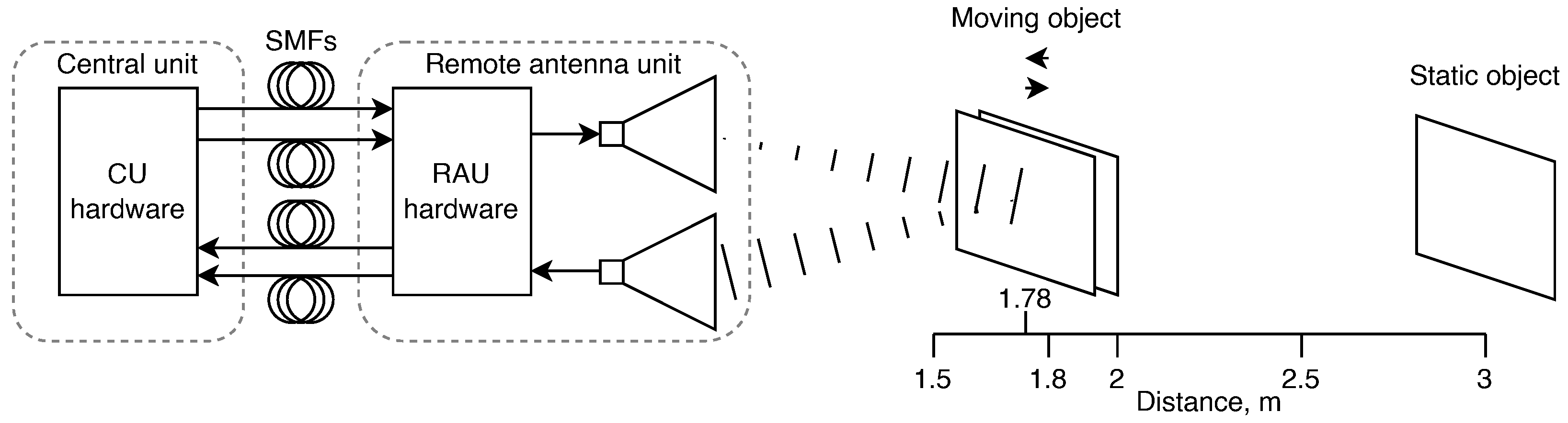
The block diagram of the experimental setup is shown in
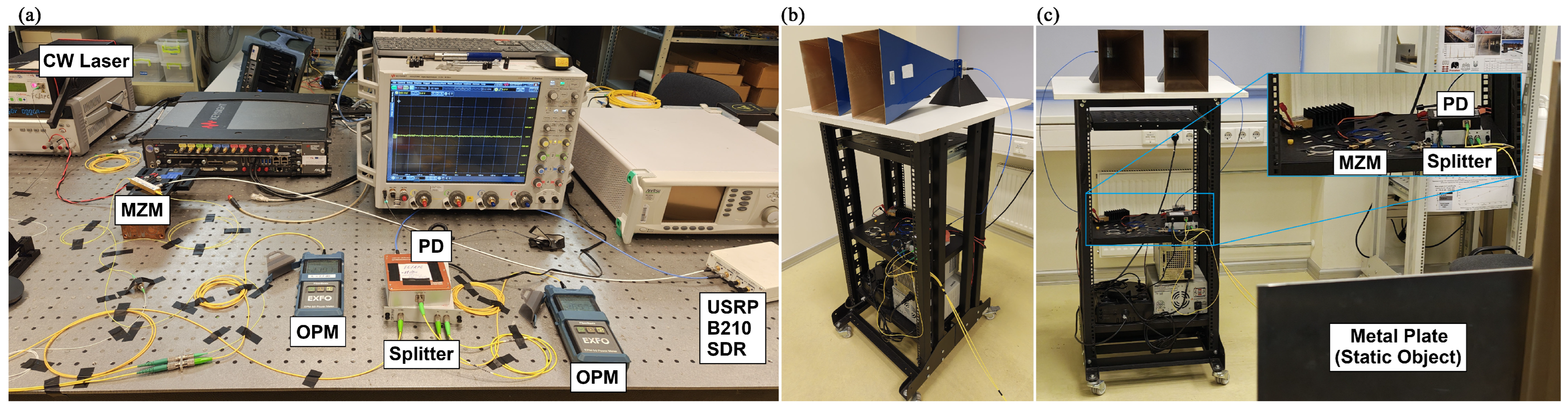
Figure 4. The photos of the experimental setup, consisting of the CU and RAU with a static reflecting object, are shown in
Figure 5.
Multiple measurements were made with a static object and a moving object—a rectangular metallic reflector, as depicted in
Figure 6. The static object was located at a distance of
from the RAU 6 GHz horn antennas. The moving object was moved by the Kingroon KP3 (SHENZHEN KINGROON TECH CO LIMITED, Hong Kong, China) 3D printer motorized rail within a range of
–
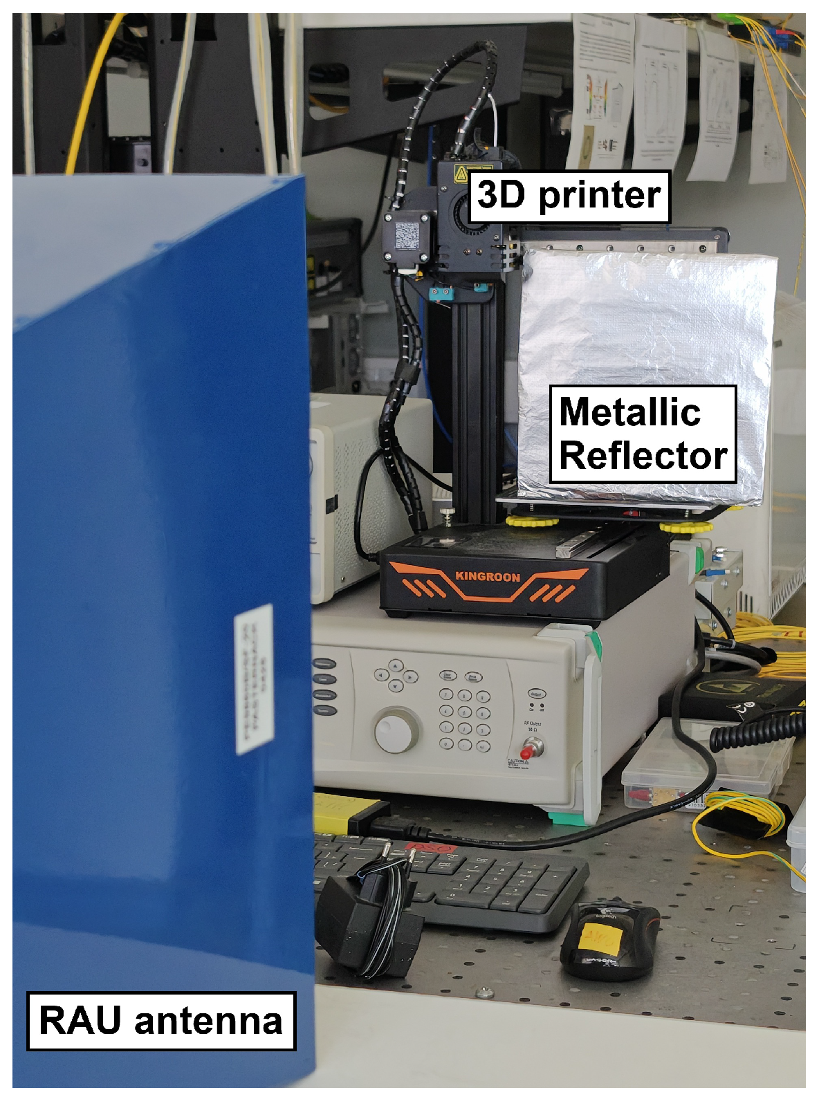
from the RAU antennas. The setup for the moving object experiment is shown in
Figure 7.
Performance evaluation was performed by transmitting
bits to enable BER measurement at the order of
(one error per measurement). This BER can be further reduced by applying FEC codes, such as the TPC, which can be seamlessly integrated into an OTFS system after QAM modulation in DD before IDZT, since the TPC structure is also two-dimensional [
33]. It should be noted that TPC is only one possible choice for coded OTFS systems; alternative coding schemes, including LDPC and polar codes, can also be integrated within the same framework.
4. Experimental Results
4.1. Static Object
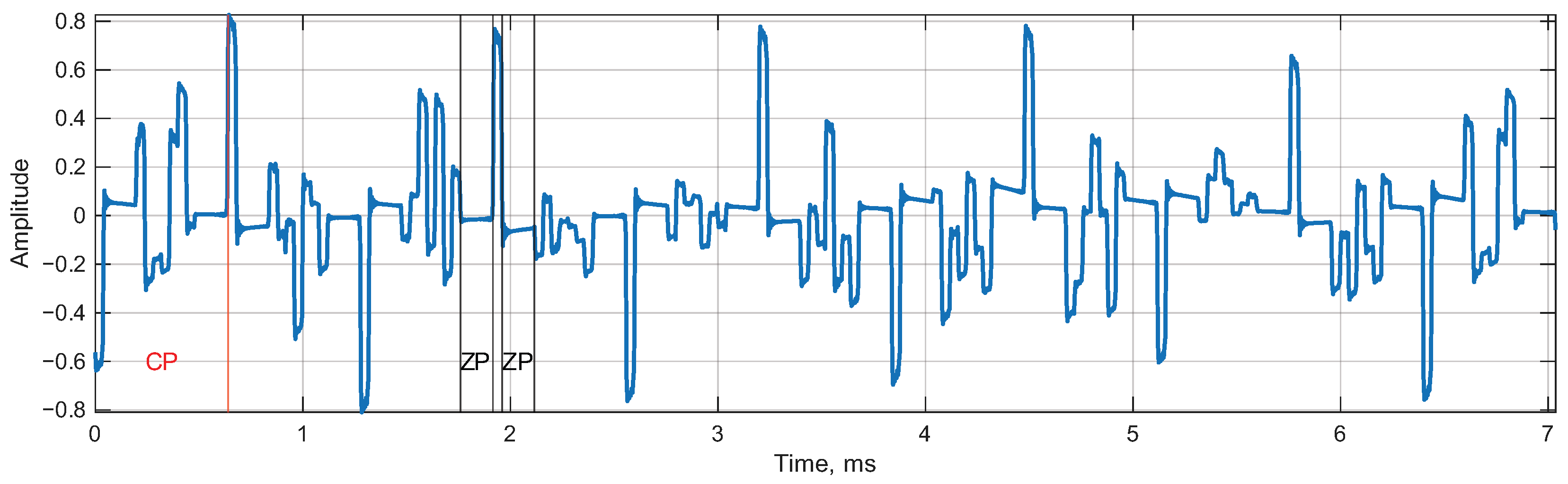
The received
waveform of a single OTFS frame is shown in
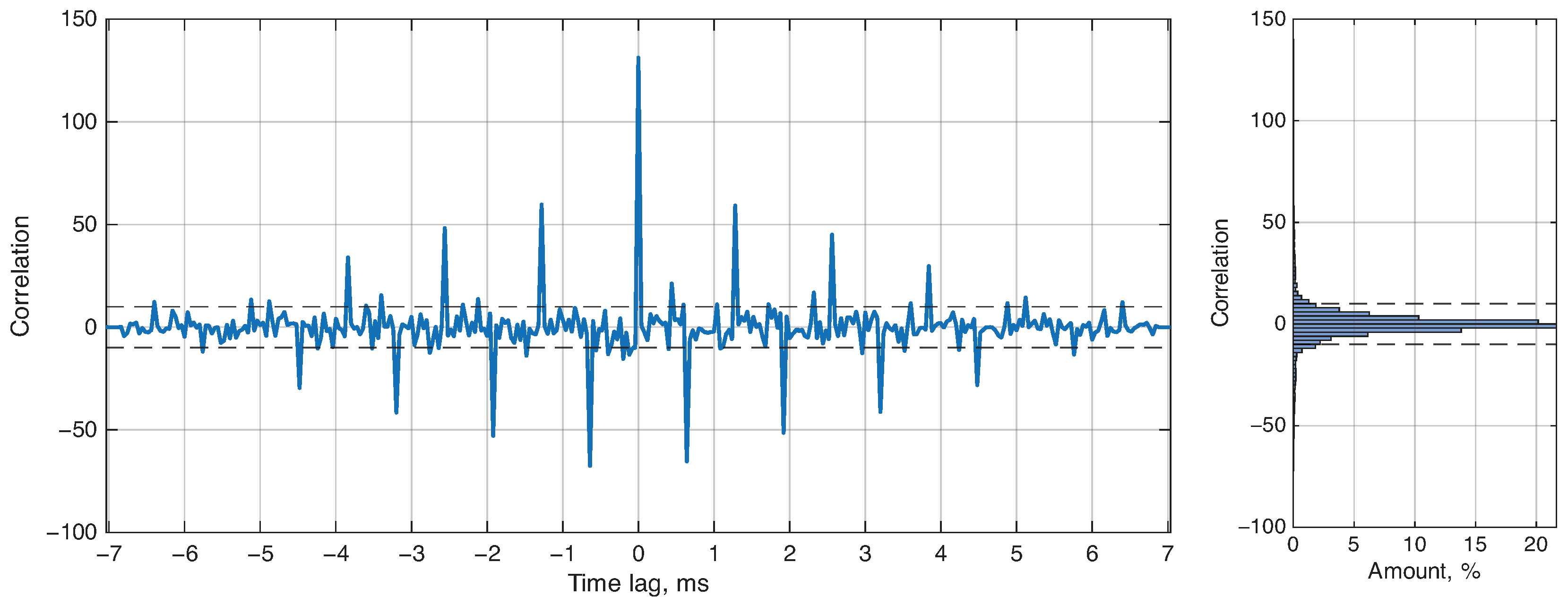
Figure 8. Averaged cross-correlation and cross-correlation distribution histogram from 14,000 OTFS frames between transmitted and received waveforms are shown in
Figure 9.
Cross-correlation between the transmitted and received waveforms shows a pattern with multiple peaks at time lags when pilot pulses overlap. At these pilot overlapping time lags, the calculated correlation does not surpass half of the correlation value at zero time lag. Looking at the histogram, which is comprised of 14,000 OTFS frames, of the correlation values are in the range .
4.1.1. Performance Depending on the Received Signal Power
Experiments with varying receiver frequency and transmitter power were conducted. The power of the received signal was calculated by averaging the whole received waveform using this formula:
where
P is the calculated signal power in
,
is the received signal vector,
K is the number of samples in the signal
, and
k is the index of the sample.
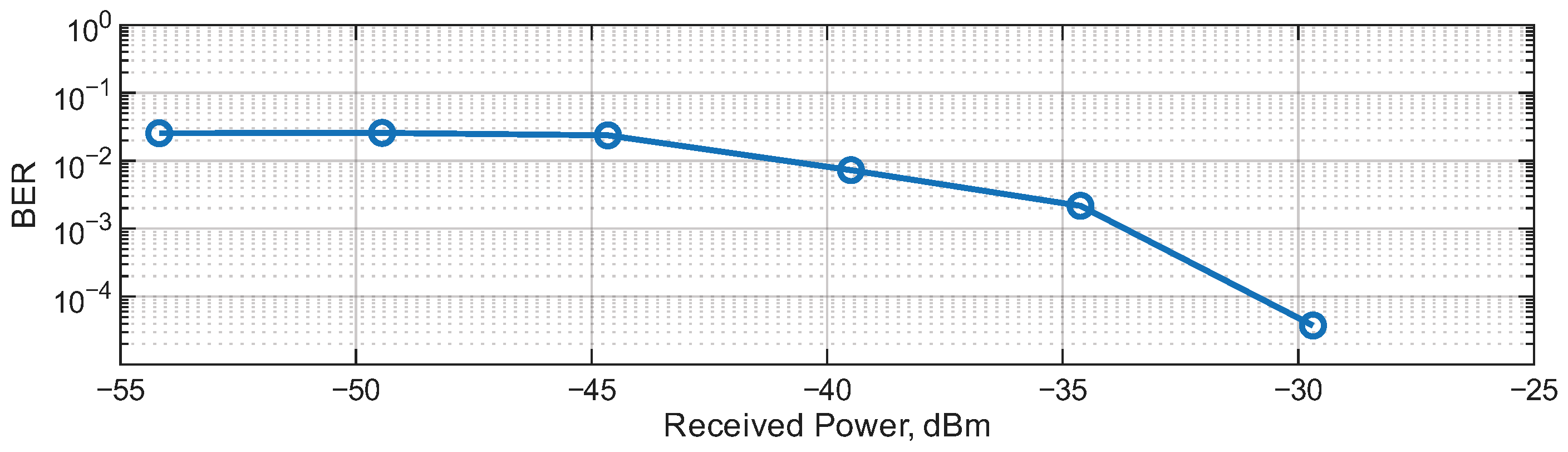
BER was measured in the optical setup, where BER, depending on the signal power at the receiver,
, is depicted in
Figure 10.
A gradual decrease in BER was observed with increased received signal power. Starting from , the recorded BER was below the estimator’s capability, indicating no errors in the received bits with the implemented OTFS system in the optical setup. The maximum transmitted power was with the SDR’s gain set at 87 , with received maximum power of , meaning that the whole optical setup’s attenuation for the maximum tested power was .
4.1.2. CFO for Mobile Object Simulation
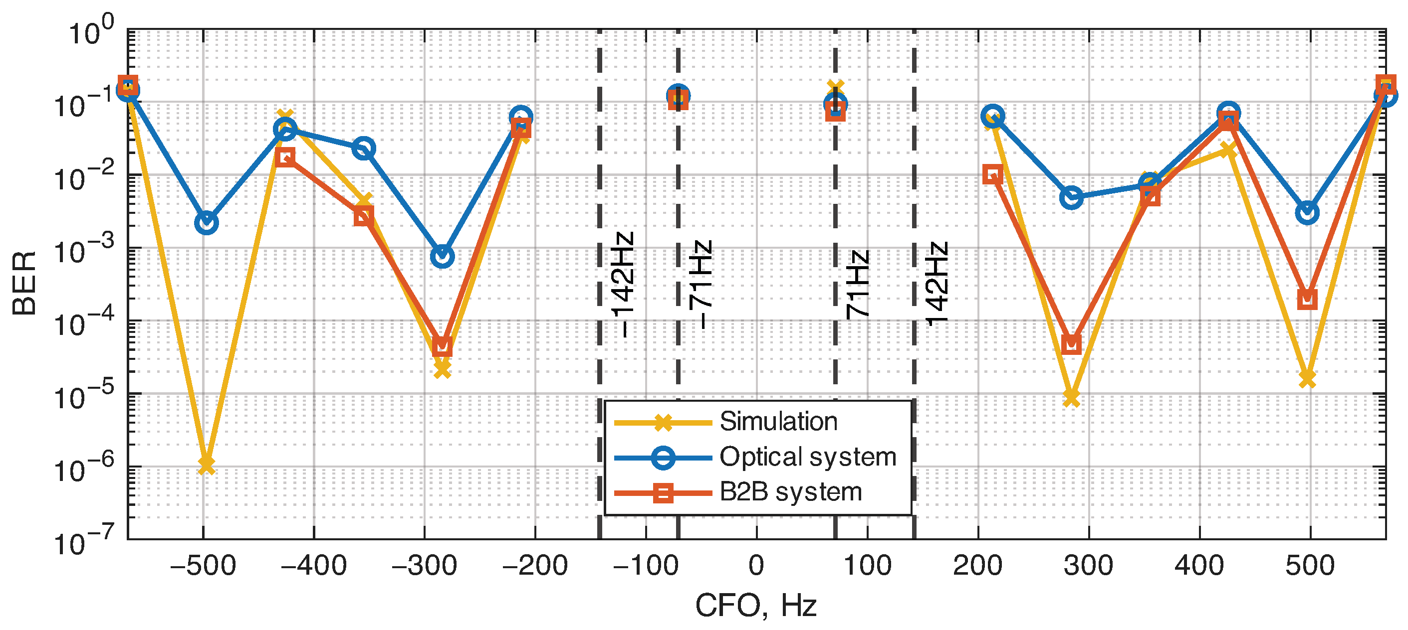
An explicit CFO was added to the receiver to simulate an ideal reflection from the moving object having a constant speed. CFO was applied in both optical and B2B setups, and the simulation without SDR. The results from these measurements are seen in
Figure 11.
In this experiment, the performance of the optical and B2B setups was not compared, as the power of the signal at the receiver was unequal:
and
for the optical and B2B setups, respectively. However, the overall dynamics of BER are still visible, as, in both setups and the simulation, only an integer Doppler shift
of 142
provides adequate communication performance, with fractional Doppler having the worst BER, rendering data transmission impossible. The demodulation in fractional Doppler is limited by the implemented LMMSE channel estimator, which increases BER to approximately
at CFOs
. Therefore, the comparison between the optical and B2B cases in
Figure 11 is qualitative rather than a strict BER benchmark between the two links. Nevertheless, both setups show the same overall OTFS behavior, namely reliable operation for integer Doppler shifts and degradation under fractional Doppler, confirming that the ARoF section preserves the proof-of-feasibility functionality of the implemented OTFS chain, while introducing an additional power-budget penalty.
4.1.3. QAM Constellations
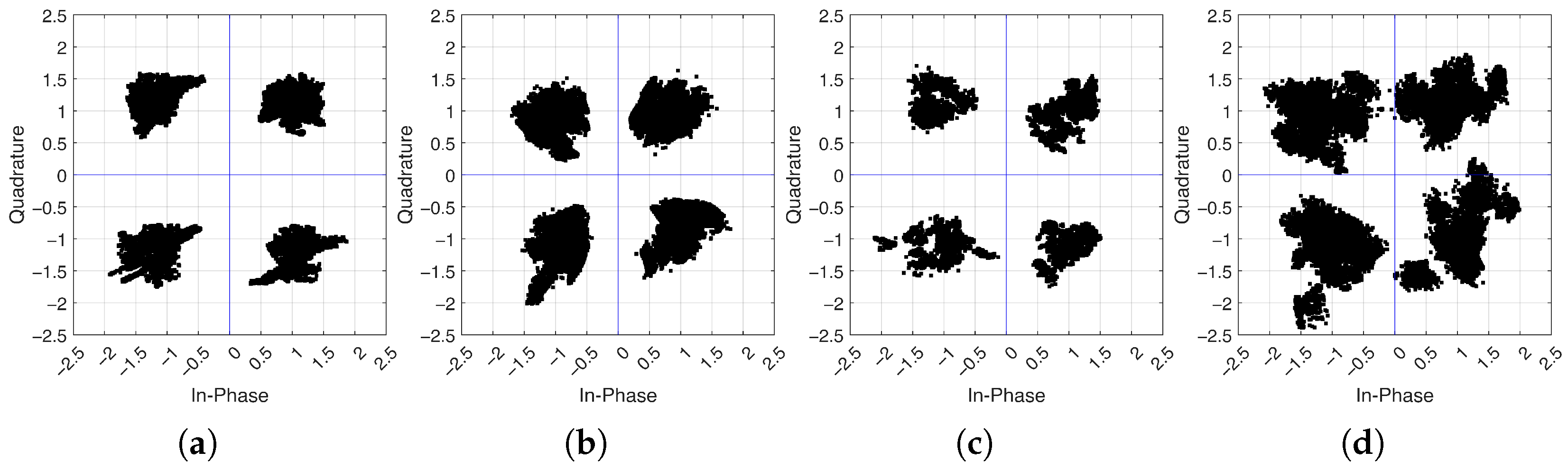
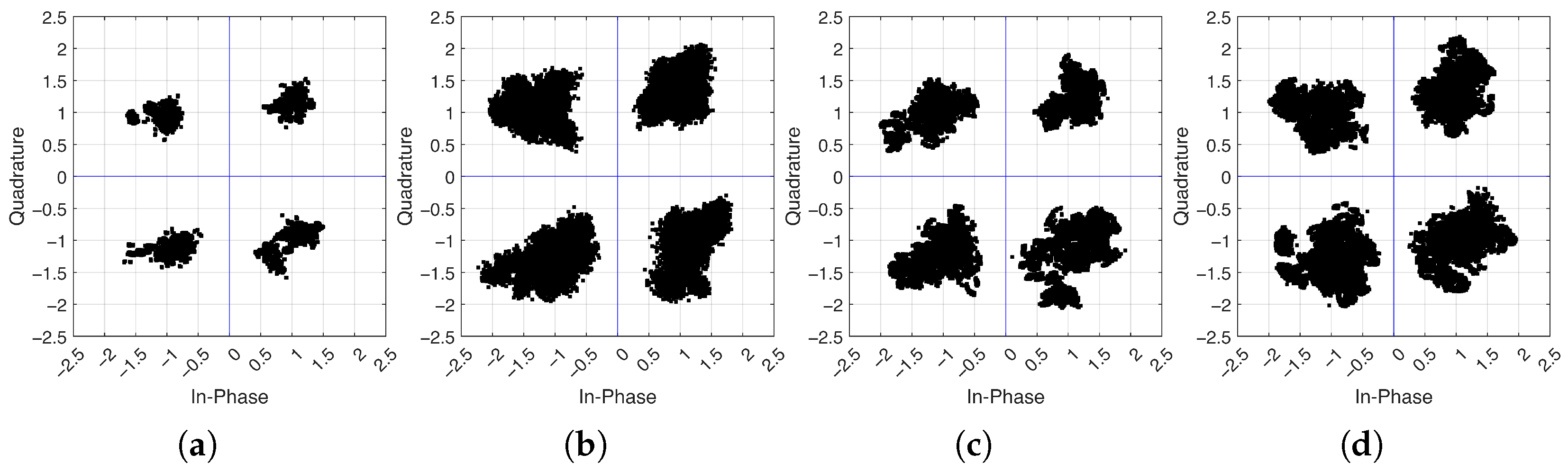
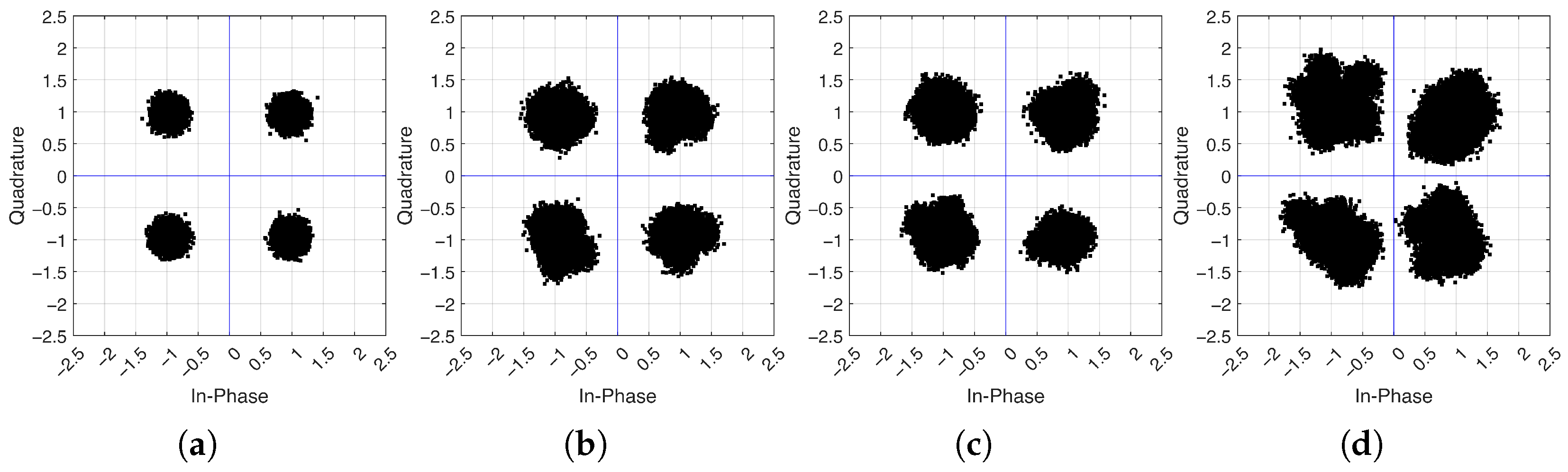
QAM constellations after OTFS demodulation were taken to assess and compare the time spread of QAM symbols in optical and B2B setups at different Doppler shifts. QAM constellations for both optical, B2B setups and simulation with different Doppler shifts—added CFOs
are shown in
Figure 12,
Figure 13 and
Figure 14, respectively.
All QAM constellation points stay in their respective quadrants, which corresponds to BER ≤ 5 × 10−
7 or 0 errors in the experiment with varied CFO. The only exception is in
Figure 12d, where slight positive and negative phase offsets for the optical link are observed.
4.2. Moving Object
In this experiment, the movement of a metallic reflector was controlled using a Kingroon KP3 3D printer, moving the reflector back and forth over a range of
–
, as depicted in
Figure 6. An accelerometer was attached to the build plate of the printer in the direction of the movement to get velocity data for comparison with the implemented system’s estimated velocity.
Using part of the DD matrix where OTFS pilots are located, it is possible to estimate the speed and direction of the object from which the pilot signal was reflected. First, normalization was applied to the channel, and the pilot was located by finding the maximum value. Then, the largest value between positive and negative Doppler taps, nearest to the pilot, is taken to be used as a second weight
in the speed estimation with a weighted average:
where
v is the estimated velocity of the object in
;
is a weight from the normalized channel with
—pilot weight and
—weight of the nearest Doppler tap with maximum weight;
is the speed of a Doppler tap in
.
Equation (
9) was applied to all received channels. As Equation (
9) uses weights from two close Doppler taps, the resulting velocity can be less than the single Doppler tap velocity resolution
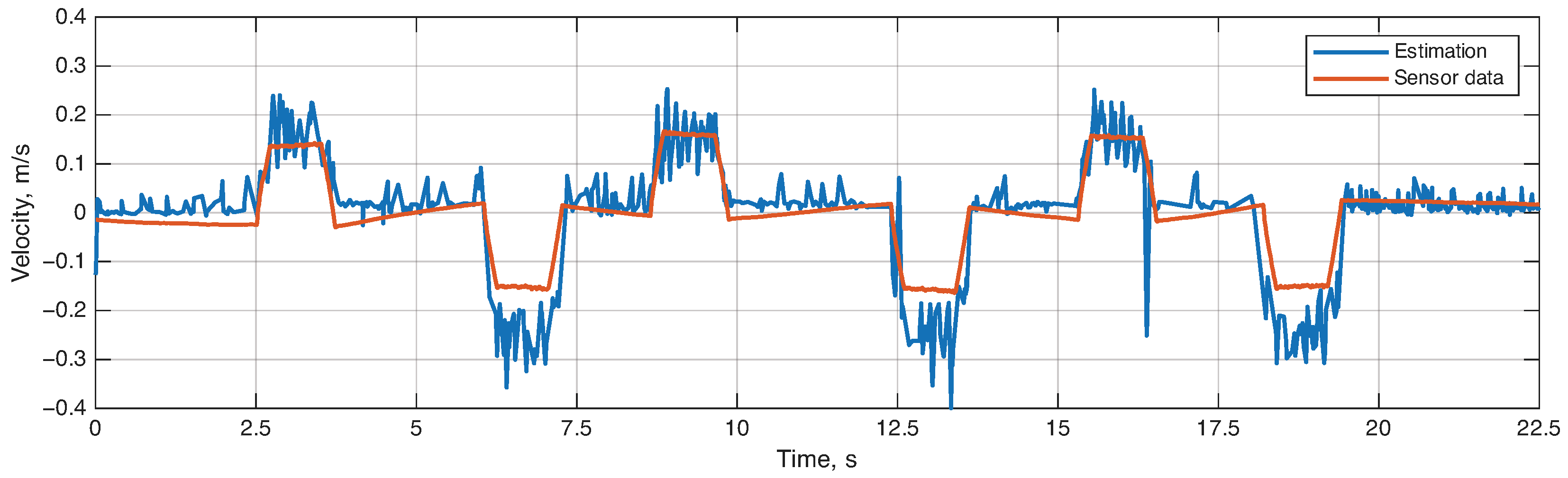
of the system. This estimation provides finer precision over the tap resolution. The estimated velocity of a moving metal plate from the start of the movement is shown in
Figure 15.
At the time of the experiment, the metallic reflector was moved forward and then back with a constant speed and a constant movement time of 1
, which is also observed in the sensor and estimated velocity graph in
Figure 15. The velocity graph clearly shows the direction of movement, with positive speed for moving forward and negative speed for moving backward from the antennas. The maximum absolute velocity of
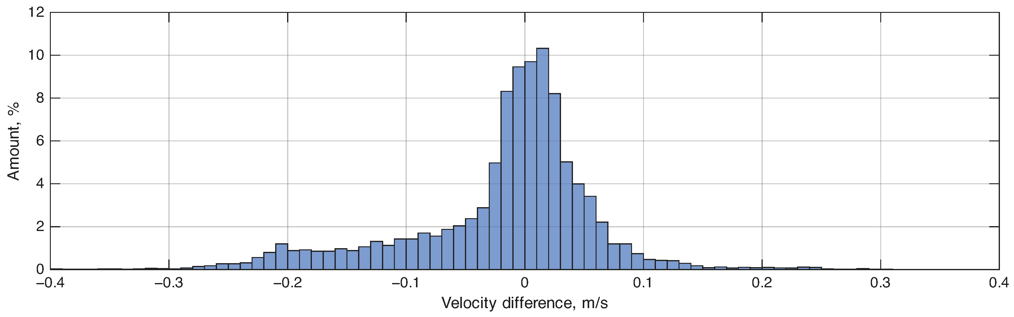
was recorded by the implemented system, which is incorrect, an absolute average velocity of an object recorded by the sensor is 0.15 m/s. This can be explained by the implemented system’s bias towards negative velocity (backward movement from the RAU), as no such increase or decrease from the expected velocity is observed for positive velocities. This bias can also be clearly observed in the error distribution shown in
Figure 16.
The amount of deviation from the expected velocity for ≤ is at and ≥ is at , with the remaining being in the range . Calculated RMSE is equal to .
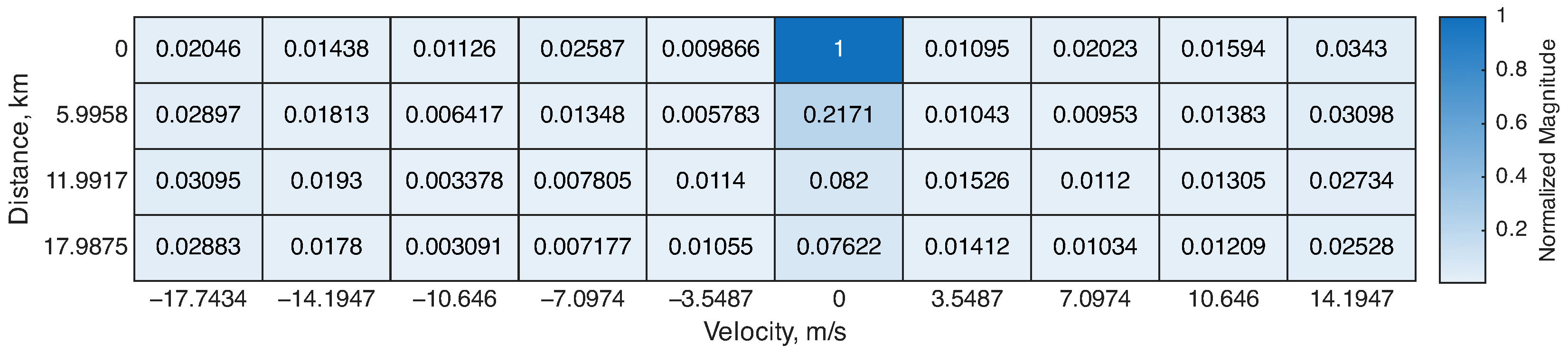
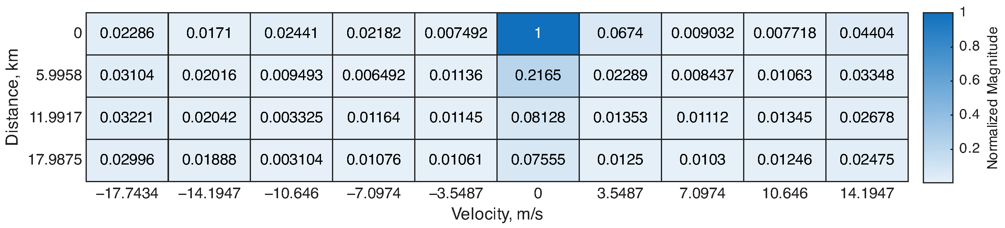
Received DD channel normalized matrices in the ZP region are shown in
Figure 17 and
Figure 18 for estimated velocity when object was static and moving towards the RAU antennas, respectively.
Both examples of received DD matrices show estimated velocity in the range of the accuracy—calculated RMSE when Formula (
9) is applied. In both cases, the majority of the pilot occupies 0 distance and velocity taps. The weight value in the distance (delay tap) beneath the pilot at 0
is present due to a sample shift in the received signal, which is due to the synchronization error. This can be improved by the use of an advanced synchronization method or system zeroing at a known distance.
5. Discussion
Existing implementations of SDR-based OTFS [
20,
21,
22,
23,
24,
25,
26,
27,
28] provide insight into OTFS and its implementation across different SDR platforms, though none include an optical link, and only some present the implementation and results for OTFS with ISAC.
From an integrated sensing perspective, an experiment with a moving metal plate confirmed that the DD domain in the OTFS system can be directly exploited for estimating movement velocity and direction. This estimation can be achieved using only channel information from the received signal with the application of DZT to transform the OTFS waveform from the time domain to the DD domain. The experiment with a moving object has also shown that the implemented system can be employed for low-complexity monostatic sensing tasks.
This study has also shown the limitations of the implemented OTFS channel estimator. Satisfactory performance with zero recorded errors has been observed with a static object without Doppler and with integer Doppler shifts, with degradation in performance in the case where fractional Doppler was present. This is consistent with the implemented LMMSE estimator at the receiver, which is not suited for fractional Doppler. LMMSE estimator also suffers from poor scalability, providing the time complexity
, which limits OTFS grid expansion to higher tap values and overall system bandwidth. Ideally, a channel estimator with low computational complexity and the ability to work in the presence of fractional Doppler should be implemented, with the proposed algorithms presented in [
34,
35,
36].
The parameters used in the SDR implementation of OTFS (see
Table 1) were primarily chosen for velocity estimation, so that it was possible to get results using available equipment in the laboratory for moving object simulation. It is possible to increase the bandwidth of the OTFS waveform, decreasing velocity resolution, which in turn will provide the ability to capture higher speeds of a mobile object, with a maximum possible absolute velocity
, which is the limit of the implemented system. This limitation also impacted the distance resolution, making it
, which is impossible to achieve experimentally without a delay simulation with hardware components. As a result of such low distance resolution
, with distance orders greater than the tested distances of
–
and 3
, the ranging of an object was not performed. To get a true joint range-velocity estimation, OTFS signal parameters of bandwidth
F, frame time
T, and carrier frequency
should be optimized for the experimental scenario, so that both meaningful distance and velocity values are captured.
The maximum limit of the bandwidth, on which both resolutions depend, of the USRP B210 SDR is 56 MHz [
37], which translates to a velocity resolution of
and distance resolution of
for any
size OTFS system at 6 GHz carrier frequency. The single tap velocity value can then be further decreased to
if
or
OTFS is used, meaning that an increase in the size of the frame increases velocity resolution, keeping distance resolution constant, as it is dependent on the signal and SDR bandwidth. For this real-time OTFS system realization, a dedicated FPGA-based implementation of OTFS demodulation algorithms should be developed, as SDR communication with a PC through the software layer adds performance overhead, limiting the possible size of an implemented OTFS DD domain and working SDR bandwidth.
Overall, the real-time SDR-based system presented in this paper should be regarded as a proof of the feasibility of an OTFS ISAC chain in an ARoF setup, rather than a fully optimized communication and sensing platform.
6. Conclusions
This paper presented a real-time OTFS-based ISAC system implemented on a USRP B210 SDR, which was experimentally validated and evaluated in both B2B and ARoF configurations. In the optical scenario, the RAU was connected to the CU through an 800 SMF span, thereby demonstrating the practical feasibility of combining OTFS, wireless transmission, and optical fronthaul within a single experimental framework. The obtained results confirm that OTFS is not only a theoretically attractive waveform for high-mobility communication and sensing, but also a viable candidate for real-time implementation in distributed radio systems.
In the optical setup with a static object—a metal plate located ≈3 m from the RAU—no bit errors were recorded in transmitted bits once the received signal power exceeded about , corresponding to a measured . Velocity and direction estimation of a moving object was successful, providing information on the velocity in real time with a calculated RMSE = 0.0839 m/s, with a clear demonstration of the acceleration and deceleration of the object.
The measured attenuation of the complete optical setup, equal to 9.65 dB at the maximum tested transmit power of −2.4 dBm, provides a reference for the power budget in future ARoF-assisted ISAC implementations using similar optical setups. The overall system concept and hardware architecture have been successfully validated, whereas additional performance gains can be achieved through further optimization and integration of a low-complexity fractional Doppler algorithm.
Future work should focus on algorithmic, software, and hardware improvements. On the signal processing side of the software, more advanced channel estimation and equalization techniques should be investigated to improve robustness against fractional Doppler. Multipath propagation and more dynamic motion scenarios should also be investigated, as those are part of signal propagation in V2V and V2X scenarios. A key direction for hardware improvement includes transitioning from the current real-time PC- and Simulink-based prototype implementation to a dedicated FPGA-based real-time architecture. The transition of the OTFS processing block to an FPGA platform would enable higher throughput and frame rates, with reduced latency and lower computational requirements for the user.
Author Contributions
Conceptualization, N.T. and A.A.; methodology, N.T. and O.A.A.; software, N.T.; validation, N.T., O.A.A. and A.A.; formal analysis, N.T., S.M. and O.A.A.; investigation, N.T., S.M., N.K. and O.N.; resources, J.B., S.S., O.O. and A.A.; data curation, N.T.; writing—original draft preparation, N.T., S.M. and O.A.A.; writing—review and editing, N.T., S.M., O.A.A., K.R., J.B., S.S. and A.A.; visualization, N.T. and S.M.; supervision, A.A.; project administration, N.T. and A.A.; funding acquisition, N.T. and O.A.A. All authors have read and agreed to the published version of the manuscript.
Funding
Nikolajs Tihomorskis’ research part has been supported by the EU Recovery and Resilience Facility within Project No 5.2.1.1.i.0/2/24/I/CFLA/003 “Implementation of consolidation and management changes at Riga Technical University, Liepaja University, Rezekne Academy of Technology, Latvian Maritime Academy and Liepaja Maritime College for the progress towards excellence in higher education, science and innovation” academic career doctoral grant (ID 1009). Omid Abbassi Aghda’s research part was conducted within the MiFuture project, which has received funding from the European Union’s Horizon Europe (HE) Marie Skłodowska-Curie Actions MiFuture HORIZON-MSCA2022-DN-01, under Grant Agreement number 101119643. The work was partially supported by Portuguese national funds through FCT—Fundação para a Ciência e a Tecnologia, I.P., and, when eligible, co-funded by EU funds under project/support UID/50008/2025 – Instituto de Telecomunicações, with DOI identifier
https://doi.org/10.54499/UID/50008/2025 accessed on 24 April 2026.
Institutional Review Board Statement
Not applicable.
Informed Consent Statement
Not applicable.
Data Availability Statement
Conflicts of Interest
The authors declare no conflicts of interest.
Abbreviations
The following abbreviations are used in this manuscript:
| 6G | sixth-generation |
| ARoF | analog radio-over-fiber |
| B2B | back-to-back |
| BER | bit error ratio |
| CFO | carrier frequency offset |
| CP | cyclic prefix |
| CRAN | centralized radio access network |
| CU | central unit |
| CW | continuous wave |
| DD | delay-Doppler |
| DT | delay-time |
| DZT | discrete Zak transform |
| FEC | forward error correction |
| FFT | fast Fourier transform |
| FPGA | field-programmable gate array |
| IDZT | inverse discrete Zak transform |
| IFFT | inverse fast Fourier transform |
| IoT | internet of things |
| ISAC | integrated sensing and communication |
| LDPC | low-density parity-check |
| LEO | low Earth orbit |
| LMMSE | linear minimum mean square error |
| MZM | Mach–Zehnder modulator |
| NTN | non-terrestrial network |
| OFDM | orthogonal frequency-division multiplexing |
| OPM | optical power meter |
| OTFS | orthogonal time-frequency space |
| OWC | optical wireless communication |
| P/S | parallel-to-serial |
| PC | personal computer |
| PD | photodetector |
| QAM | quadrature amplitude modulation |
| RAU | remote antenna unit |
| RF | radio frequency |
| RMSE | root mean square error |
| S/P | serial-to-parallel |
| SDR | software-defined radio |
| SMF | single-mode optical fiber |
| TPC | Turbo product code |
| UE | user equipment |
| USRP | universal software radio peripheral |
| V2V | vehicle-to-vehicle |
| V2X | vehicle-to-everything |
| VLC | visible light communication |
| ZP | zero padding |
References
- Ai, B.; Lu, Y.; Fang, Y.; Niyato, D.; He, R.; Chen, W.; Zhang, J.; Ma, G.; Niu, Y.; Zhong, Z. 6G-Enabled Smart Railways. Proc. IEEE 2025, 113, 1192–1235. [Google Scholar] [CrossRef] [Scilit]
- Abboud, M.K.; Sabbar, B.M. Performance evaluation of high mobility OFDM channel estimation techniques. Int. J. Electr. Comput. Eng. (IJECE) 2020, 10, 2562–2568. [Google Scholar] [CrossRef] [Scilit]
- Mohammed, H.A.; Sibley, M.J.N.; Mather, P.J. Investigation of Doppler Effects on high mobility OFDM-MIMO systems with the support of High Altitude Platforms (HAPs). J. Phys. Conf. Ser. 2012, 364, 012048. [Google Scholar] [CrossRef] [Scilit]
- Boud, H.; Rao, R.K. OFDM-IM Performance Analysis in Presence of Doppler Frequency Shift. In Proceedings of the 2024 6th International Communication Engineering and Cloud Computing Conference (CECCC); IEEE: New York, NY, USA, 2024; pp. 31–35. [Google Scholar] [CrossRef] [Scilit]
- Zhou, Y.; Yin, H.; Xiong, J.; Song, S.; Zhu, J.; Du, J.; Chen, H.; Tang, Y. Overview and Performance Analysis of Various Waveforms in High Mobility Scenarios. In Proceedings of the 2024 7th International Conference on Communication Engineering and Technology (ICCET); IEEE: New York, NY, USA, 2024; pp. 35–40. [Google Scholar] [CrossRef] [Scilit]
- Lorca Hernando, J.; Armada, A.G. Frequency-Modulated OFDM: A New Waveform for High-Mobility Wireless Communications. IEEE Trans. Commun. 2023, 71, 540–552. [Google Scholar] [CrossRef] [Scilit]
- Gao, Z.; Deng, X.; Zou, X.; Ma, W.; Pan, W.; Yan, L. OFDM Signal Equalization in Delay-Doppler Space with High Mobility. IEEE Photonics Technol. Lett. 2026, 38, 992–995. [Google Scholar] [CrossRef] [Scilit]
- Gong, J.; Yang, Y.; Wang, Z.; Wang, D.; Liu, X.; Peng, M. Frequency-Doppler Division Multiplexing Modulation—A Waveform Design for High Doppler Communications. IEEE Commun. Lett. 2024, 28, 1288–1292. [Google Scholar] [CrossRef] [Scilit]
- Aboutorab, N.; Hardjawana, W.; Vucetic, B. A New Iterative Doppler-Assisted Channel Estimation Joint with Parallel ICI Cancellation for High-Mobility MIMO-OFDM Systems. IEEE Trans. Veh. Technol. 2012, 61, 1577–1589. [Google Scholar] [CrossRef] [Scilit]
- Ashraf, M.; Shahid, A.; Yeo, W.Y.; Lee, K.G. Energy Efficient Doppler Assisted Channel Estimation for Highly Mobile OFDM Systems. Int. J. Distrib. Sens. Netw. 2015, 11, 892151. [Google Scholar] [CrossRef] [Scilit]
- Hadani, R.; Rakib, S.; Tsatsanis, M.; Monk, A.; Goldsmith, A.J.; Molisch, A.F.; Calderbank, R. Orthogonal Time Frequency Space Modulation. In Proceedings of the 2017 IEEE Wireless Communications and Networking Conference (WCNC); IEEE: New York, NY, USA, 2017; pp. 1–6. [Google Scholar] [CrossRef] [Scilit]
- Lampel, F.; Avarado, A.; Willems, F.M. On OTFS using the Discrete Zak Transform. In Proceedings of the 2022 IEEE International Conference on Communications Workshops (ICC Workshops); IEEE: New York, NY, USA, 2022; pp. 729–734. [Google Scholar] [CrossRef] [Scilit]
- Kumar, G.; Bhatia, V.; Juntti, M. Sparse Delay Doppler Estimation for Zak-OTFS Enabled ISAC System. In Proceedings of the 2025 IEEE 5th International Symposium on Joint Communications & Sensing (JC&S); IEEE: New York, NY, USA, 2025; pp. 1–6. [Google Scholar] [CrossRef] [Scilit]
- Mohammed, S.K. Derivation of OTFS Modulation From First Principles. IEEE Trans. Veh. Technol. 2021, 70, 7619–7636. [Google Scholar] [CrossRef] [Scilit]
- Buzzi, S.; Caire, G.; Colavolpe, G.; D’Andrea, C.; Foggi, T.; Piemontese, A.; Ugolini, A. LEO Satellite Diversity in 6G Non-Terrestrial Networks: OFDM vs. OTFS. IEEE Commun. Lett. 2023, 27, 3013–3017. [Google Scholar] [CrossRef] [Scilit]
- Okoyeigbo, O.; Deng, X.; Imoize, A.L.; Shobayo, O. OTFS: A Potential Waveform for Space–Air–Ground Integrated Networks in 6G and Beyond. Telecom 2025, 6, 19. [Google Scholar] [CrossRef] [Scilit]
- Winkler, S.; Villanueva, S.K.; Tekin, T.; Symeonidis, M.; Abadian, S.; Sirbu, B. Analog Radio over Fiber transmission of OTFS modulated signals. In Proceedings of the 2024 54th European Microwave Conference (EuMC); IEEE: New York, NY, USA, 2024; pp. 1098–1101. [Google Scholar] [CrossRef] [Scilit]
- Xu, C.; Zhang, X.; Petropoulos, P.; Sugiura, S.; Maunder, R.G.; Yang, L.L.; Wang, Z.; Yuan, J.; Haas, H.; Hanzo, L. Optical OTFS is Capable of Improving the Bandwidth-, Power- and Energy-Efficiency of Optical OFDM. IEEE Trans. Commun. 2024, 72, 938–953. [Google Scholar] [CrossRef] [Scilit]
- Kepezkaya, T.; Tek, Y.I.; Basar, E. Flip-OTFS for Optical Wireless Communications. In Proceedings of the 2025 33rd Signal Processing and Communications Applications Conference (SIU); IEEE: New York, NY, USA, 2025; pp. 1–4. [Google Scholar] [CrossRef] [Scilit]
- Tihomorskis, N.; Migla, S.; Cirjulina, D.; Aboltins, A. Software Defined Radio Prototyping of Direct Detection OTFS for Optical Wireless Links. In Proceedings of the 2026 IEEE 23rd Consumer Communications & Networking Conference (CCNC); IEEE: New York, NY, USA, 2026; pp. 1–5. [Google Scholar] [CrossRef] [Scilit]
- Mirabella, M.; Di Viesti, P.; Vitetta, G.M. Implementation of an OTFS-DCP-Based Communication System on Software-Defined Radios. In Proceedings of the 2025 IEEE Wireless Communications and Networking Conference (WCNC); IEEE: New York, NY, USA, 2025; pp. 1–7. [Google Scholar] [CrossRef] [Scilit]
- Rasendria, F.; Hamid, E.Y.; Izzuddin, A.; Saefiana, R.; Nusantara, F.Y.G. Implementation of an Orthogonal Time Frequency Space (OTFS) Transmitter Based on Software-Defined Radio (SDR). In Proceedings of the 2025 International Conference on Radar, Antenna, Microwave, Electronics, and Telecommunications (ICRAMET); IEEE: New York, NY, USA, 2025; pp. 127–132. [Google Scholar] [CrossRef] [Scilit]
- Thaj, T.; Viterbo, E. OTFS Modem SDR Implementation and Experimental Study of Receiver Impairment Effects. In Proceedings of the 2019 IEEE International Conference on Communications Workshops (ICC Workshops); IEEE: New York, NY, USA, 2019; pp. 1–6. [Google Scholar] [CrossRef] [Scilit]
- Karpovich, P.; Zielinski, T.; Maksymiuk, R.; Abratkiewicz, K.; Tomikowski, P.; Samczyński, P. Experimental Testing of an OTFS-Modulated Waveform in a Joint Radar-Comm System. In Proceedings of the 2023 IEEE Radar Conference (RadarConf23); IEEE: New York, NY, USA, 2023; pp. 1–6. [Google Scholar] [CrossRef] [Scilit]
- Shi, Y.; Li, B.; Wei, X.; Huang, H. Experimental Implementation of an OTFS-Based ISAC System. In Proceedings of the 2024 IEEE/CIC International Conference on Communications in China (ICCC Workshops); IEEE: New York, NY, USA, 2024; pp. 587–592. [Google Scholar] [CrossRef] [Scilit]
- Yang, Z.; Wang, Q.; Liu, G.; Ma, Z. UAV Detection Based on OTFS ISAC System. In Proceedings of the 2025 IEEE 101st Vehicular Technology Conference (VTC2025-Spring); IEEE: New York, NY, USA, 2025; pp. 1–7. [Google Scholar] [CrossRef] [Scilit]
- Zieliński, T.P.; Karpovich, P.; Abratkiewicz, K.; Maksymiuk, R.; Samczyński, P.; Duda, K.; Wypich, M. Wireless OTFS-Based Integrated Sensing and Communication for Moving Vehicle Detection. IEEE Sens. J. 2024, 24, 6573–6583. [Google Scholar] [CrossRef] [Scilit]
- Wei, X.; Yuan, W.; Zhang, K.; Liu, F. OTFS-Assisted ISAC System: Delay Doppler Channel Estimation and SDR-Based Implementation. IEEE Trans. Mob. Comput. 2025, 24, 11865–11878. [Google Scholar] [CrossRef] [Scilit]
- Wang, Y.; Di, S.; Du, D.; Song, Y.; Zhang, Q.; Zhang, J.; Wang, M.; Yu, J. Photonics-Assisted Millimeter-Wave Integrated Sensing and Communication Based on OTFS. J. Light. Technol. 2025, 43, 10512–10520. [Google Scholar] [CrossRef] [Scilit]
- He, J.; Yin, L.; Liu, K.; Xiao, S.; Chen, Z. Zero-Padding 2D-DFT Scheme for Photonics-Assisted W-Band Fiber-Wireless ISAC System with Orthogonal Time Frequency Space Modulation. J. Light. Technol. 2025, 43, 9561–9567. [Google Scholar] [CrossRef] [Scilit]
- Hussain, K.; Ali, E.M.; Hussain, W.; Raza, A.; Elkamchouchi, D.H. Robust OTFS-ISAC for Vehicular-to-Base Station End-to-End Sensing and Communication. Electronics 2025, 14, 4340. [Google Scholar] [CrossRef] [Scilit]
- Yan, J.; Zheng, F.; Li, Y.; Pan, M.; Wu, Y.; Liu, J.; Chen, F.; Wang, Y.; Wu, G.; Li, X.; et al. A Technical Review of Integrated Sensing and Communication in Optical Transmission System. In Proceedings of the 2023 21st International Conference on Optical Communications and Networks (ICOCN); IEEE: New York, NY, USA, 2023; pp. 1–3. [Google Scholar] [CrossRef] [Scilit]
- Koganei, Y.; Sugitani, K. Comparison of FEC Design Concepts for Higher Error Correction Performance with Utilizing Turbo Product Code. In Proceedings of the 2024 Optical Fiber Communications Conference and Exhibition (OFC); IEEE: New York, NY, USA, 2024; pp. 1–3. [Google Scholar]
- He, X.; Fan, P.; Wang, Q. A Two-Stage Channel Estimation Algorithm for OTFS in Fractional Doppler Channels. IEEE Commun. Lett. 2023, 27, 1839–1843. [Google Scholar] [CrossRef] [Scilit]
- Zegrar, S.E.; Haif, H.; Arslan, H. OTFS-Based ISAC for Super-Resolution Range-Velocity Profile. IEEE Trans. Commun. 2024, 72, 3934–3946. [Google Scholar] [CrossRef] [Scilit]
- Jitsumatsu, Y.; Sun, L. Two-Stage Prony-Based Estimation of Fractional Delay and Doppler Shifts in OTFS Modulation. In Proceedings of the 2025 IEEE 36th International Symposium on Personal, Indoor and Mobile Radio Communications (PIMRC); IEEE: New York, NY, USA, 2025; pp. 1–6. [Google Scholar] [CrossRef] [Scilit]
- Ettus Research. USRP B210 (Board Only). Available online: https://www.ettus.com/all-products/ub210-kit/ (accessed on 11 April 2026).
Figure 1.
Optical link usage scenario example with OTFS DD matrix visualization at the base station, received by the RAU unit.
Figure 1.
Optical link usage scenario example with OTFS DD matrix visualization at the base station, received by the RAU unit.
Figure 2.
Block diagram of an OTFS communication system based on the SDR.
Figure 2.
Block diagram of an OTFS communication system based on the SDR.
Figure 3.
DD and DT domain matrices. (a) Real part of before the IFFT step of IDZT in DD. (b) Real part of after the IFFT step of IDZT in DT.
Figure 3.
DD and DT domain matrices. (a) Real part of before the IFFT step of IDZT in DD. (b) Real part of after the IFFT step of IDZT in DT.
Figure 4.
Block diagram of an optical setup with distinct CU and RAU parts.
Figure 4.
Block diagram of an optical setup with distinct CU and RAU parts.
Figure 5.
Experimental setup. (a) CU part of the setup containing a CW laser, an MZM, a PD, and an SDR. (b) RAU part of the setup containing two 6 GHz horn antennas. (c) RAU in the back and a metal plate in the front, used as a static object.
Figure 5.
Experimental setup. (a) CU part of the setup containing a CW laser, an MZM, a PD, and an SDR. (b) RAU part of the setup containing two 6 GHz horn antennas. (c) RAU in the back and a metal plate in the front, used as a static object.
Figure 6.
Simplified optical system setup with moving and static objects used in the experiments.
Figure 6.
Simplified optical system setup with moving and static objects used in the experiments.
Figure 7.
Measurement setup with a 3D printer used for object movement with a metallic reflector on top of the 3D printer’s build plate.
Figure 7.
Measurement setup with a 3D printer used for object movement with a metallic reflector on top of the 3D printer’s build plate.
Figure 8.
OTFS waveform received after reflection from a static object.
Figure 8.
OTFS waveform received after reflection from a static object.
Figure 9.
Averaged cross-correlation (left) and distribution histogram (right) between transmitted and received OTFS frame waveforms.
Figure 9.
Averaged cross-correlation (left) and distribution histogram (right) between transmitted and received OTFS frame waveforms.
Figure 10.
BER depending on the power of the received signal in the optical setup.
Figure 10.
BER depending on the power of the received signal in the optical setup.
Figure 11.
BER depending on the CFO between the SDR transmitter and receiver in optical (blue) and B2B (orange) setups, and implemented OTFS system’s simulation (yellow).
Figure 11.
BER depending on the CFO between the SDR transmitter and receiver in optical (blue) and B2B (orange) setups, and implemented OTFS system’s simulation (yellow).
Figure 12.
QAM constellations after OTFS demodulation with SDR in optical link. (a) Doppler shift Hz. (b) Hz. (c) Hz. (d) Hz.
Figure 12.
QAM constellations after OTFS demodulation with SDR in optical link. (a) Doppler shift Hz. (b) Hz. (c) Hz. (d) Hz.
Figure 13.
QAM constellations after OTFS demodulation with SDR in B2B link. (a) Doppler shift Hz. (b) Hz. (c) Hz. (d) Hz.
Figure 13.
QAM constellations after OTFS demodulation with SDR in B2B link. (a) Doppler shift Hz. (b) Hz. (c) Hz. (d) Hz.
Figure 14.
QAM constellations after OTFS demodulation in the simulation. (a) Doppler shift Hz. (b) Hz. (c) Hz. (d) Hz.
Figure 14.
QAM constellations after OTFS demodulation in the simulation. (a) Doppler shift Hz. (b) Hz. (c) Hz. (d) Hz.
Figure 15.
Estimated velocity of a moving metallic reflector from a recorded part of the received channels.
Figure 15.
Estimated velocity of a moving metallic reflector from a recorded part of the received channels.
Figure 16.
Distribution histogram of the difference between estimated and via sensor recorded velocities over 16,000 OTFS frames.
Figure 16.
Distribution histogram of the difference between estimated and via sensor recorded velocities over 16,000 OTFS frames.
Figure 17.
Received normalized DD matrix of a metallic reflector in a static position. Estimated velocity m/s.
Figure 17.
Received normalized DD matrix of a metallic reflector in a static position. Estimated velocity m/s.
Figure 18.
Received normalized DD matrix of a metallic reflector moving towards the antennas at the velocity of m/s. Estimated velocity m/s.
Figure 18.
Received normalized DD matrix of a metallic reflector moving towards the antennas at the velocity of m/s. Estimated velocity m/s.
Table 1.
Parameters of the SDR OTFS ISAC system.
Table 1.
Parameters of the SDR OTFS ISAC system.
| Parameter | Description | Value |
|---|
| Carrier frequency, GHz | 6 |
| Carrier wavelength, m | |
| N | Number of time slots (Doppler bins) | 10 |
| M | Number of subcarriers (delay bins) | 16 |
| Length of the CP in samples | 16 |
| Length of the ZP in delay taps | 4 |
| T | Frame time, ms | 7 |
| Single tap delay resolution, μs | 40 |
| Single tap distance resolution, km | |
| SDR bandwidth, kHz | 250 |
| F | OTFS signal bandwidth, kHz | |
| Single tap Doppler resolution, Hz | |
| Doppler range, Hz | |
| Single tap velocity resolution, m/s | |
| Disclaimer/Publisher’s Note: The statements, opinions and data contained in all publications are solely those of the individual author(s) and contributor(s) and not of MDPI and/or the editor(s). MDPI and/or the editor(s) disclaim responsibility for any injury to people or property resulting from any ideas, methods, instructions or products referred to in the content. |





 ,
,