Article

Quad-Band Truncated Square-Shaped MIMO Terahertz Antenna for Beyond 5G and 6G Communications
by
Jeremiah O. Abolade
1,2,
Pradeep Kumar
3,* and
Dominic B. O. Konditi
4
1
Department of Electrical Engineering, Institute for Basic Sciences, Technology and Innovation, Pan African University, Nairobi 254002, Kenya
2
Department of Electrical and Electronic Engineering, Bowen University, Iwo 232112, Nigeria
3
Discipline of Electrical, Electronic and Computer Engineering, University of KwaZulu-Natal, Durban 4041, South Africa
4
Department of Electrical Engineering, The Technical University of Kenya, Nairobi 254002, Kenya
*
Author to whom correspondence should be addressed.
Technologies 2026, 14(1), 59; https://doi.org/10.3390/technologies14010059
Submission received: 3 December 2025 / Revised: 28 December 2025 / Accepted: 5 January 2026 / Published: 13 January 2026

Abstract

A compact quad-band multiple-input multiple-output (MIMO) antenna for terahertz communications is presented in this work. The proposed antenna consists of a truncated square patch with inverted-U-shaped and C-shaped slots. The operating frequencies of the proposed antenna are 0.38 THz, 0.43 THz, 0.61 THz, and 0.7 THz, with reflection coefficients of −13.8 dB, −22.1 dB, −27.3 dB, and −14.8 dB, respectively, and a −10 dB impedance bandwidth of 9 GHz, 18 GHz, 18 GHz, and 21 GHz, respectively. The peak gain values of a single element antenna at 0.38 THz, 0.43 THz, 0.61 THz, and 0.7 THz are 3.3 dB, 4.8 dB, 4.7 dB, and 5.5 dB, respectively. The dual-triangular MIMO configuration was investigated. The peak gains of the MIMO configurations at 0.38 THz, 0.43 THz, 0.61 THz, and 0.7 THz are 10.6 dB, 12.2 dB, 15.6 dB, and 15.2 dB, respectively. The envelope correlation coefficient (ECC) and the diversity gain (DG) of the proposed antenna were investigated and are presented herein. The proposed MIMO antenna demonstrates lower coupling and higher isolation at the operating frequency bands. Therefore, it is a suitable candidate for beyond 5G and 6G wireless communications applications, such as for nanodevices used in the internet of things and in wearables.

1. Introduction

Terahertz communication is the future of wireless communication [1,2]. This is because of the ever-increasing desire of end-users of a high-speed, high-bandwidth, and low-latency communication experience. The terahertz band, which spans 0.1–10 THz, meets all of the above conditions. In addition, terahertz radiation is less harmful compared with the microwave band [3]. These characteristics have drawn the attention of researchers in recent times to the terahertz band [4,5,6,7,8,9,10,11]. It finds applications in areas such as terahertz imaging (medical diagnostics, material inspection, and security screening), high resolution spectroscopy (for chemical and biological sensing), space and satellite communications, the internet of things and wearable devices, military and surveillance systems, and wireless chip-to-chip communication.
As the enabler of wireless communication, the antenna in this band has to be designed and investigated. Therefore, researchers’ attention has been drawn to the design and investigation of terahertz antennas [4,5,6,7,12,13,14]. For example, a wideband planar antenna is presented in [14], which operates within 0.1–10 THz and is built on 0.3 λ o × 0.1 λ o @ 0.8   T H z . In [7], the authors proposed a lotus-shaped terahertz antenna with a defected ground plane, using a polyamide substrate with a footprint of 2.53 λ g × 2.53 λ g @ 8.96   T H z .
A multiband antenna at terahertz frequencies enables ultra-high-speed communication, efficient spectrum utilization, compact design, and enhanced sensing by operating across multiple bands simultaneously, improving performance, reliability, and versatility. Therefore, researchers have begun to develop a terahertz antenna that is capable of operating at more than one frequency (multiband) [5,15]. For instance, a terahertz multiband antenna for sub-THz applications with a footprint of 150 × 200 × 80 µm3 built on the RT/duroid 5880 substrate was presented by the authors in [15]. For instance, the author of [5] presented a tri-band bio-inspired antenna etched on a 0.17 λ g × 0.34 λ g @ 0.17   T H z duroid substrate, with a sevaral slots based radiating patch The fractal geometry used was radiating patch.
The design of terahertz MIMO antennas for extremely large-scale arrays is critical for next-generation wireless systems requiring ultra-high data rates and low latency [2]. At THz frequencies, large-aperture arrays often operate in the near-field, where spherical-wave propagation significantly affects the radiation pattern, mutual coupling, and element performance. These near-field effects, combined with the high propagation loss and low SNR, necessitate antenna designs that maximize effective gain, directivity, and polarization diversity while ensuring uniform performance across the array [2,16]. Optimizing array geometry, element spacing, and mutual coupling mitigation enables robust multi-element operation, efficient beamforming, and spatial multiplexing, making THz large-scale MIMO antennas suitable for applications such as ultra-dense indoor networks, high-speed backhaul, and high-resolution localization and sensing systems [2,17].
Multiple-input multiple-output (MIMO) scenarios at terahertz bands have also been explored by the researchers [18,19]. A graphene-based 2 × 2 MIMO antenna was presented in [18]. The authors used an octagonal short-angular circular patch on a substrate of dimension 1.17 λ o   × 1.1 λ o @0.259 THz operating over 0.259–0.324 THz. A bio-inspired terahertz antenna was proposed by the authors in [19]. The antenna is based on a palmate leaf shape, fed with a four-port MIMO configuration, and was investigated and presented in the study. The footprint of the antenna is 0.75 λ g ×   0.75 λ g @2.38 THz on a polyamide substrate and it operates from 2.38 THz to 11.18 THz.
In this work, a compact quad-band truncated square patch (TSP) antenna is presented. The antenna is based on a truncated square shape with inverted U-shaped and C-shaped slots etched on the duroid 5882 substrate of dimension 0.38 λ g × 0.38 λ g @0.38 THz. The contributions of this work are as follows: i. Presentation of a compact truncated-square-shaped quad-band terahertz antenna; ii. application of hybrid slot shapes (inverted U-shaped and C-shaped slots) for a quad-band antenna without compromising the gain and radiation efficiency; and iii. presentation of a 5 × 5 compact MIMO terahertz antenna with a high gain, low coupling, and high diversity gain.
The arrangement of the rest of this work is as follows: the design methodology is presented in Section 2. The results and discussion of the single element are presented in Section 3. Section 4 presents the parametric analysis. The MIMO antenna design and diversity parameter analysis is presented in Section 5. Section 6 presents the comparative analysis of the proposed TSP and TSP-MIMO antennas and the conclusion is presented in Section 7.

2. TSP Antenna Design Methodology

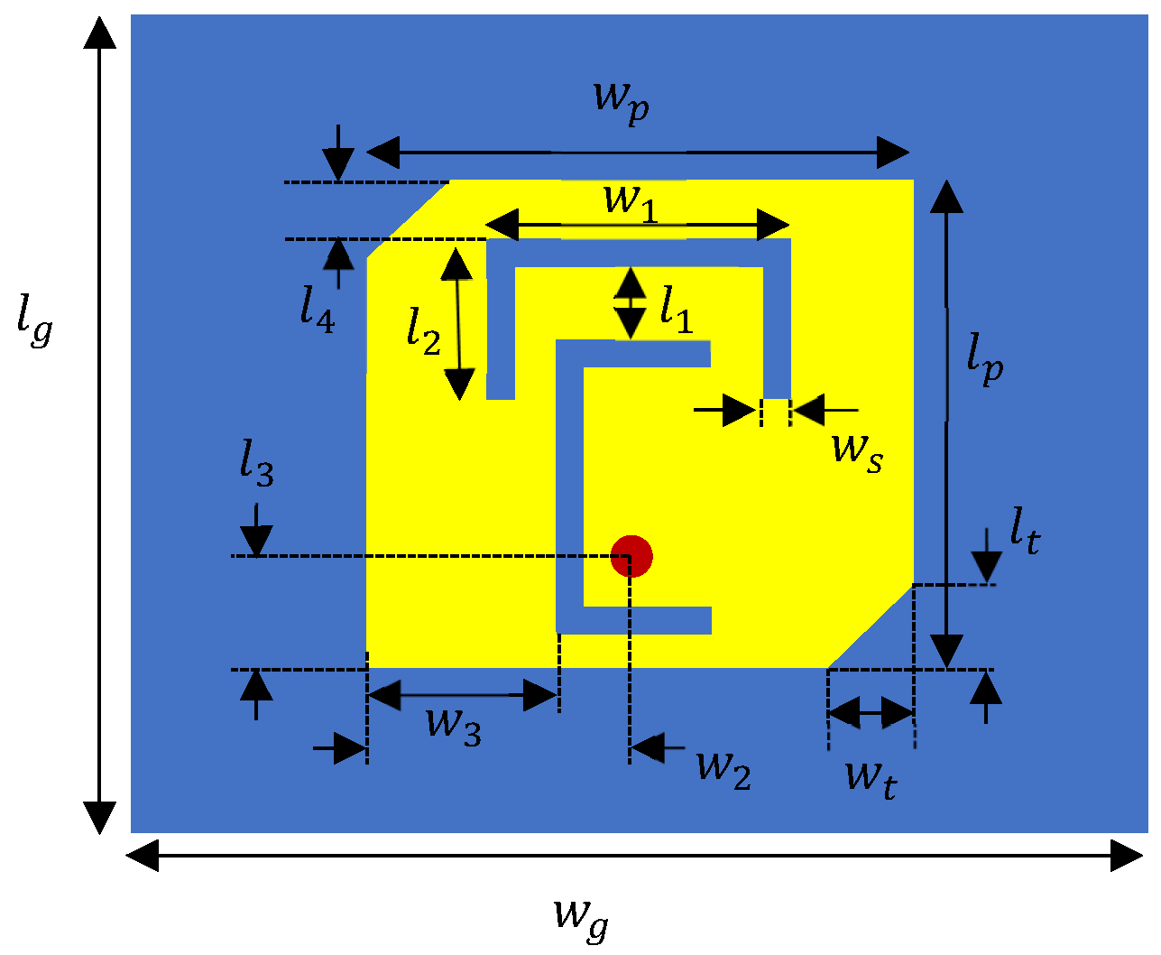
The design of the TSP antenna begins with a square patch fed with a coaxial cable that is offset from the center of the radiating patch, as shown in Figure 1a. The patch is designed to operate at 0.46 THz based on Equations (1)–(4) [20]. The square patch is orthogonally truncated as shown in Figure 1b. The third stage is the slotting of the inverted-U shape for miniaturization purposes, as shown in Figure 1c. The last stage is the incorporation of the C-shaped slot as shown in Figure 1d. The dimensions of the TSPS antenna are shown in Figure 2 and the parametric values are presented in Table 1. Based on the material characterization presented in [21], duroid 5880 at 0.29 THz has a permittivity of 2.28 and a loss tangent of 0.0009. Duroid 5880 is used due to its stability as the frequency increases and its small absorption coefficients and loss tangents [21]. The antenna is simulated in a radiation boundary condition box and the automatic mesh setting is used for accurate results.
f r = c 2 L e f f ε e f f  
L e f f = L + 2 L  
L = 0.412 d ε e f f + 0.3 w d + 0.264 ε e f f 0.258 w d + 0.8
ε e f f = ε r + 1 2 + ε r 1 2 1 + 12 t w  

3. Results and Discussion

3.1. Reflection Coefficient

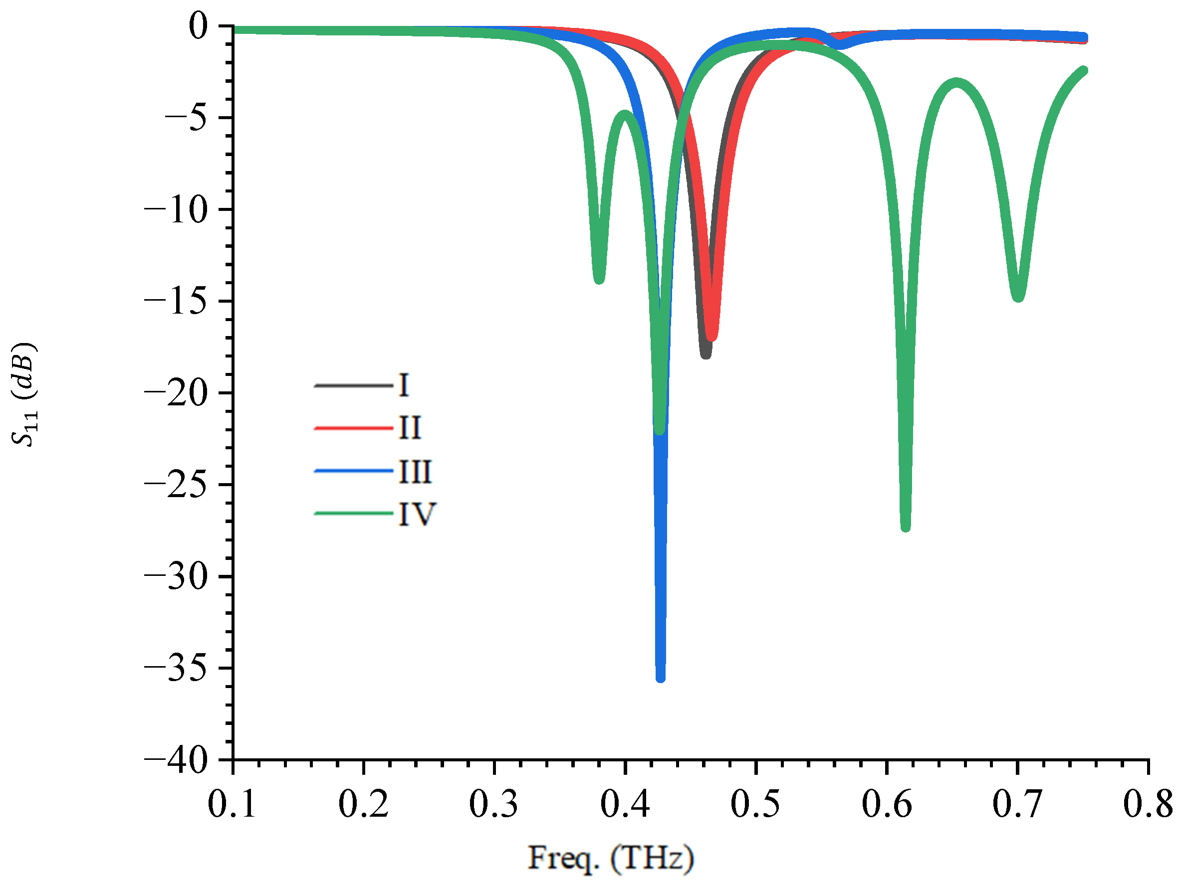
The reflection coefficient of the TPS antenna is shown in Figure 3. It can be observed that the original initiator patch (I) resonated at 0.46 THz with a reflection coefficient of −17.9 dB, as shown in Figure 3. The truncated patch (II) results in an increase in the resonant frequency, from 0.46 THz to 0.47 THz. This is due to the reduction in the effective area of the radiating patch. The introduction of the inverted U-shape (III) leads to a lowering in the resonant frequency, from 0.47 THz to 0.43 THz, which is an 8.51% reduction, as shown in Figure 3. The further introduction of a C-shaped slot (IV) excited three extra resonances at 0.38 THz, 0.61 THz, and 0.7 THz. Therefore, the use of U-shaped and C-shaped slots leads to quad resonant frequencies of 0.38 THz, 0.43 THz, 0.61 THz, and 0.7 THz with reflection coefficients of −13.8 dB, −22.1 dB, −27.3 dB, and −14.8 dB, respectively.
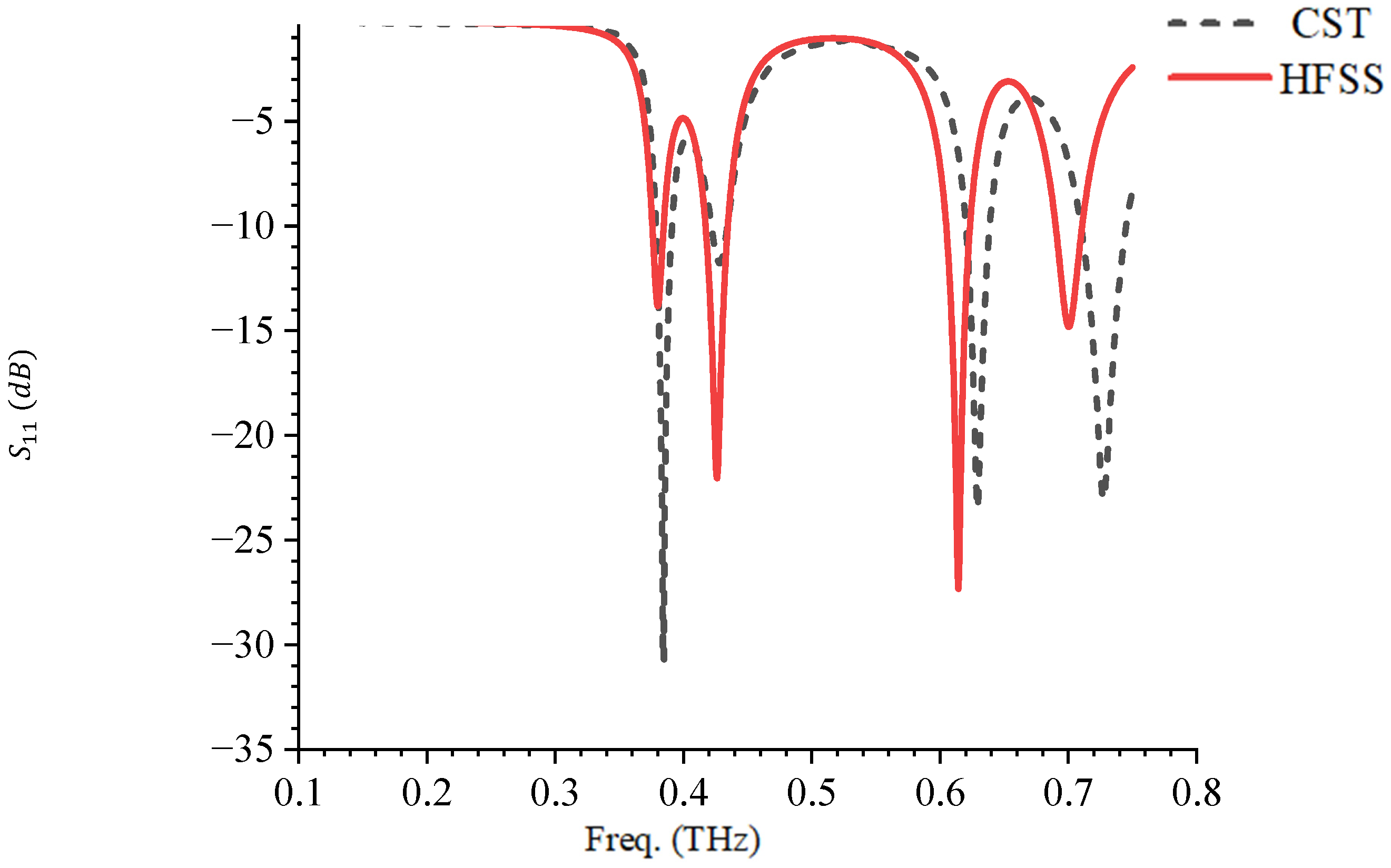
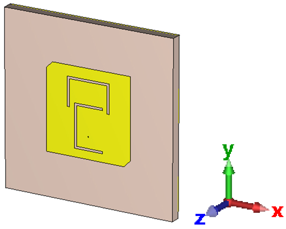
The proposed TPS antenna is validated using the finite difference time domain (FDTD)-based simulator CST microwave studio and the setup is as shown in Figure 4. The reflection coefficient response of the FDTD-based CST model is compared with the finite element method-based HFSS model, presented in Figure 5. It can be seen that there is good agreement between the resonance responses obtained from CST and HFSS for the proposed TSP antenna.

3.2. Gain, Radiation Patterns, and Radiation Efficiency

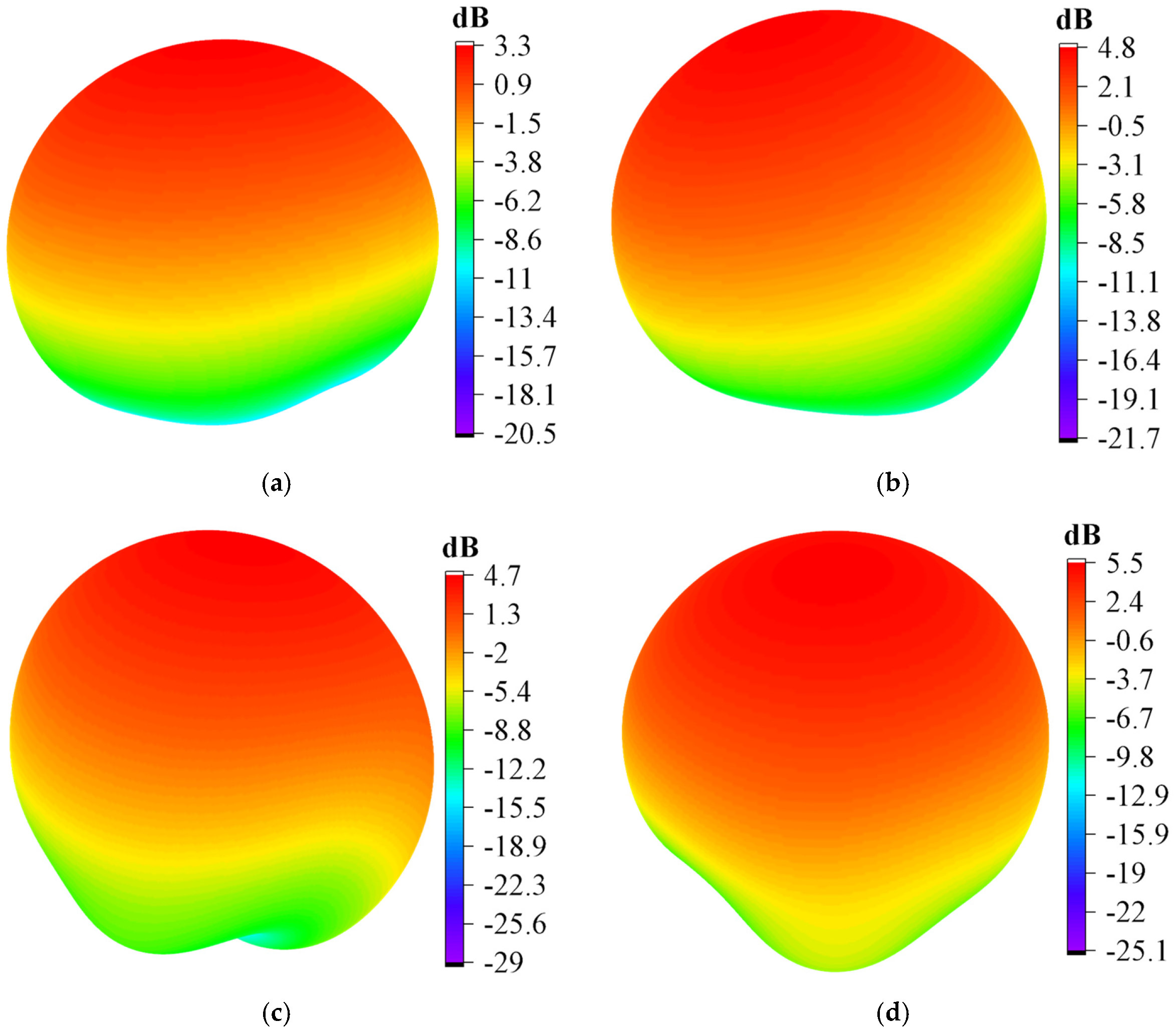
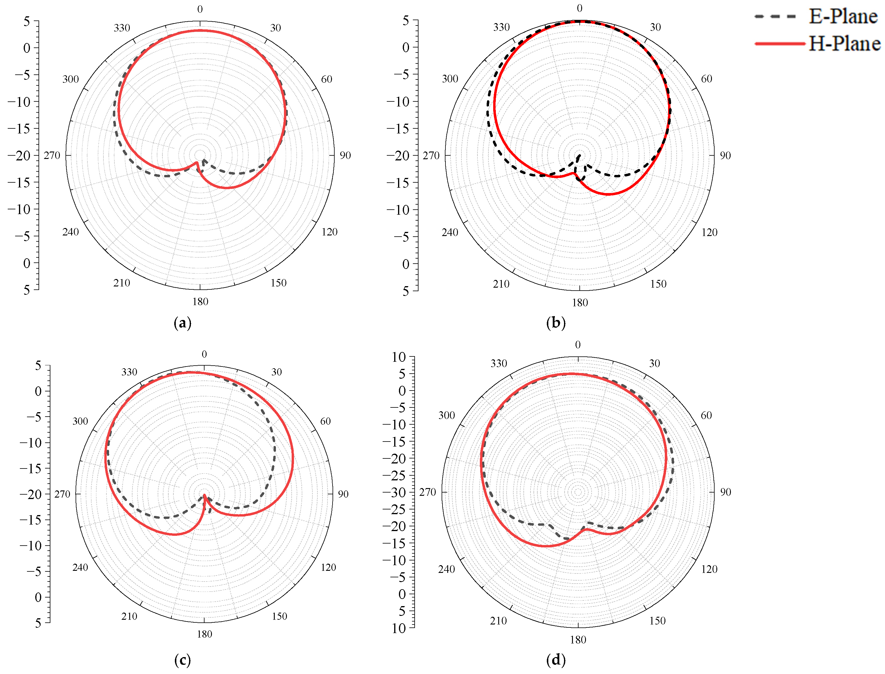
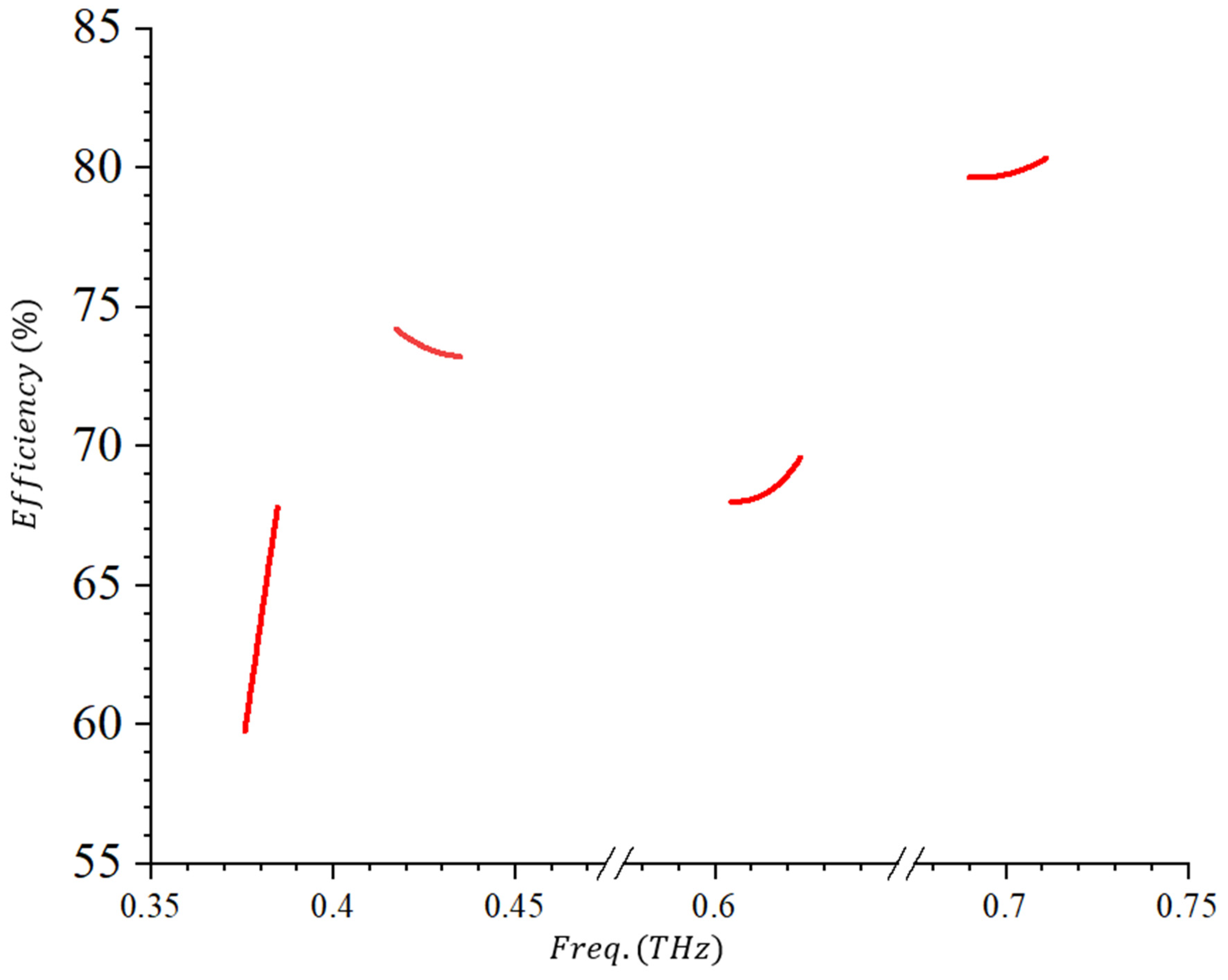
The 3D gain of the TPS antenna is presented in Figure 6. It can be observed that the gains at 0.38 THz, 0.43 THz, 0.61 THz, and 0.7 THz are 3.3 dB, 4.8 dB, 4.7 dB, and 5.5 dB, respectively. The radiation patterns at both E-plane and H-plane are observed at the resonant frequencies shown in Figure 7. Figure 8 shows the radiation efficiency at the resonant frequencies. It can be observed that at the first band (0.376–0.385 THz) the radiation efficiency is in the range of 60–68%, as shown in Figure 8. Figure 8 reveals that at the second band (0.417−0.435 THz), the radiation efficiency is in the range of 73–74%. At the third band (0.605–0.623 THz), the radiation efficiency is in the range of 68–70% and the radiation efficiency at the last band (0.690–0.711 THz) is in the range of 79–81%, as shown in Figure 8. This shows that the TPS antenna radiation efficiency is within the acceptable range, making it a suitable candidate for future terahertz wireless communication.

3.3. Surface Current Distribution

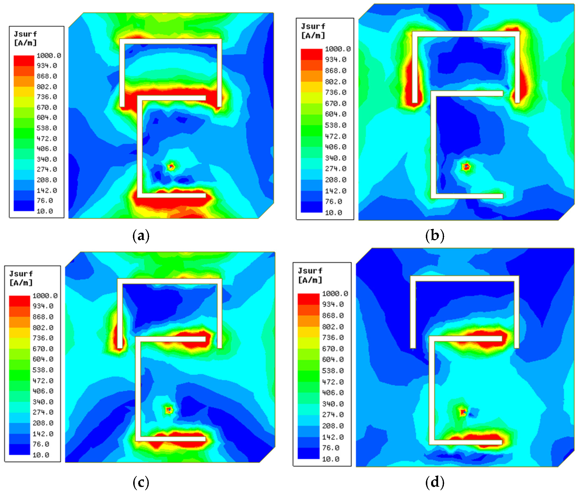
The surface current distribution of the antenna shows how the antenna structure contributes at each resonant frequency. It gives the design engineers a functional insight into how each part of the antenna contributes to the resonant frequencies and helps the antenna engineer with further manipulation and enhancement. In a multi-slot antenna, the dominance of a certain slot at certain frequencies is due to its effective electrical length, its orientation, and the mutual coupling of the adjacent slots at those frequencies. Each slot behaves as a resonant path whose dominant resonance occurs when its effective length is an approximate fraction of the guided wavelength.
The surface current distributions of the TPS antenna at each of the resonant frequencies are presented in Figure 9. It can be observed in Figure 9a that both slots contributed to the resonance at 0.38 THz, but the C-shaped slots contributed the most as the highest surface current is seen around the C-shaped slot. At 0.43 THz, it can be observed that the inverted-U-shaped slot is responsible for the resonance seen in Figure 9b. This shows that even without the C-shaped slot, resonance at 0.43 THz still exists, as shown in Figure 3. Figure 9c shows the surface current distribution at 0.61 THz. It can be observed that the C-shaped slot contributed the most, with a small contribution from the inverted-U-shaped slot, as shown in Figure 9c. The C-shaped slot is responsible for the resonance seen at 0.7 THz, as shown in Figure 9d.

4. Parametric Analysis

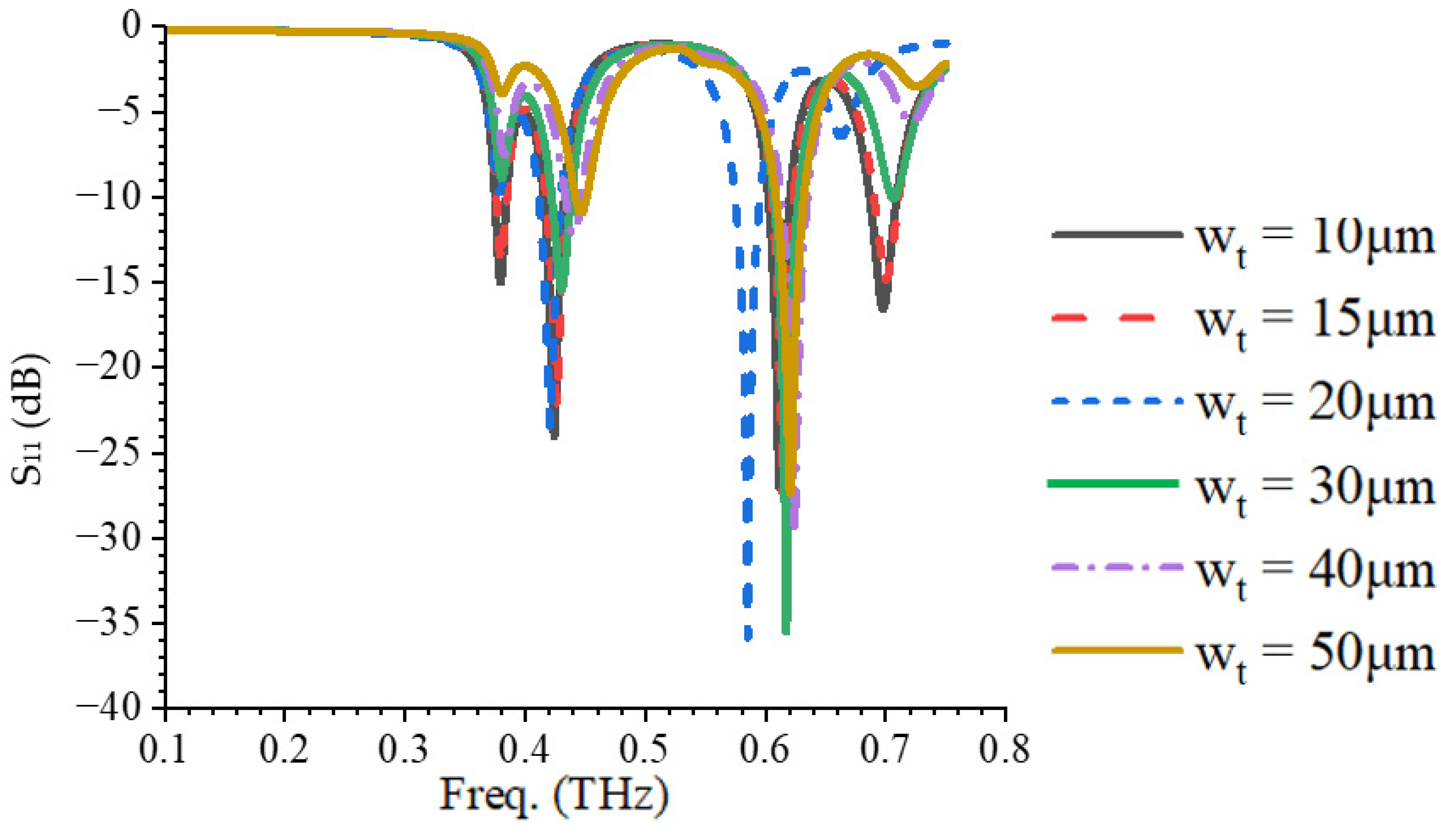
In this section, a parametric analysis of the TPS antenna is presented. The impact of each of the parameters l 1 ,   w t ,   w 1 ,   and   w s on the resonant frequencies and the reflection coefficients are investigated.

4.1. Variational Effect of l 1 on the Reflection Coefficient

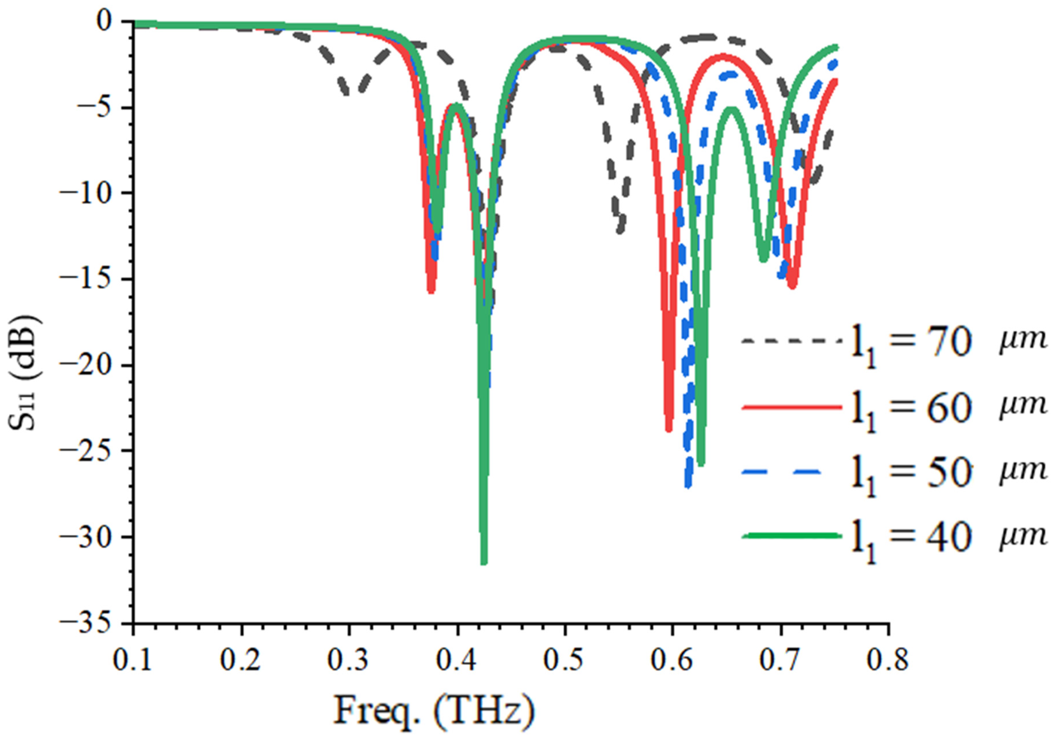
The effect of variation in l 1 (the gap between the inverted-U-shaped slot and the C-shaped slot) on the reflection coefficient is presented in Figure 10. It can be observed that change in l 1 results in a shift of resonant frequencies at the last two upper bands when l 1 is between 40   μ m   and 60   μ m . It is worth noting that the shift in the resonant frequency is noticed at the fundamental resonant frequency when l 1 is 70   μ m , as shown in Figure 10. No shift in resonant frequency is observed at the second band for all the variations. This is to validate the fact that the C-shape has little or no contribution to the resonance at 0.43 THz, although it affects the reflection coefficient as shown in Figure 10. In terms of the bandwidth, when l 1 = 50   μ m , the bandwidth is 0.008 (0.3763–0.3845) THz, 0.0164 (0.4170–0.4334) THz, 0.019 (0.6048–0.6234) THz, and 0.021 (0.6903–0.7113) THz at the first, second, third, and fourth operating bands, respectively, while it is 0.011 (0.3718–0.3828) THz, 0.0171 (0.4143–0.4314) THz, 0.017 (0.5871–0.6041) THz, and 0.022 (0.7003–0.7223) THz, at the first, second, third, and fourth operating bands, respectively, when l 1 = 60   μ m . Therefore, it can be observed that an increase in l 1 of the proposed TSP antenna improves the bandwidth.

4.2. Variational Effect of w t on the Reflection Coefficient

Figure 11 shows the variational effect of the change in w t on the reflection coefficient. It can be observed that the effect of a change in w t is more pronounced on the reflection coefficient than the resonant frequencies. As w t increases, the reflection coefficient increases and there is an upward shift in the resonant frequencies. This shows that as w t increases, the effective area of the radiating patch reduces and the antenna matching is poorly affected. The effect of w t on the reflection coefficient is less pronounced at 0.61 THz as shown in Figure 11. With regard to the bandwidth, when w t = 10   μ m , the bandwidth is 0.0079 (0.3762–0.3841) THz, 0.0166 (0.4155–0.4321) THz, 0.0183 (0.6034–0.6234) THz, and 0.0211 (0.6863–0.7074) THz at the first, second, third, and fourth operating bands, respectively, while at w t = 15   μ m the bandwidth is 0.0079 (0.3762–0.3841) THz, 0.0176 (0.4174–0.4350) THz, 0.0183 (0.6034–0.6217) THz, and 0.0188 (0.6914–0.7102) THz at the first, second, third, and fourth operating bands, respectively. Therefore, it can be observed that a variation in l 1 has an insignificant effect on the −10 dB bandwidth of the proposed TSP antenna.

4.3. Variational Effect of w 1 on the Reflection Coefficient

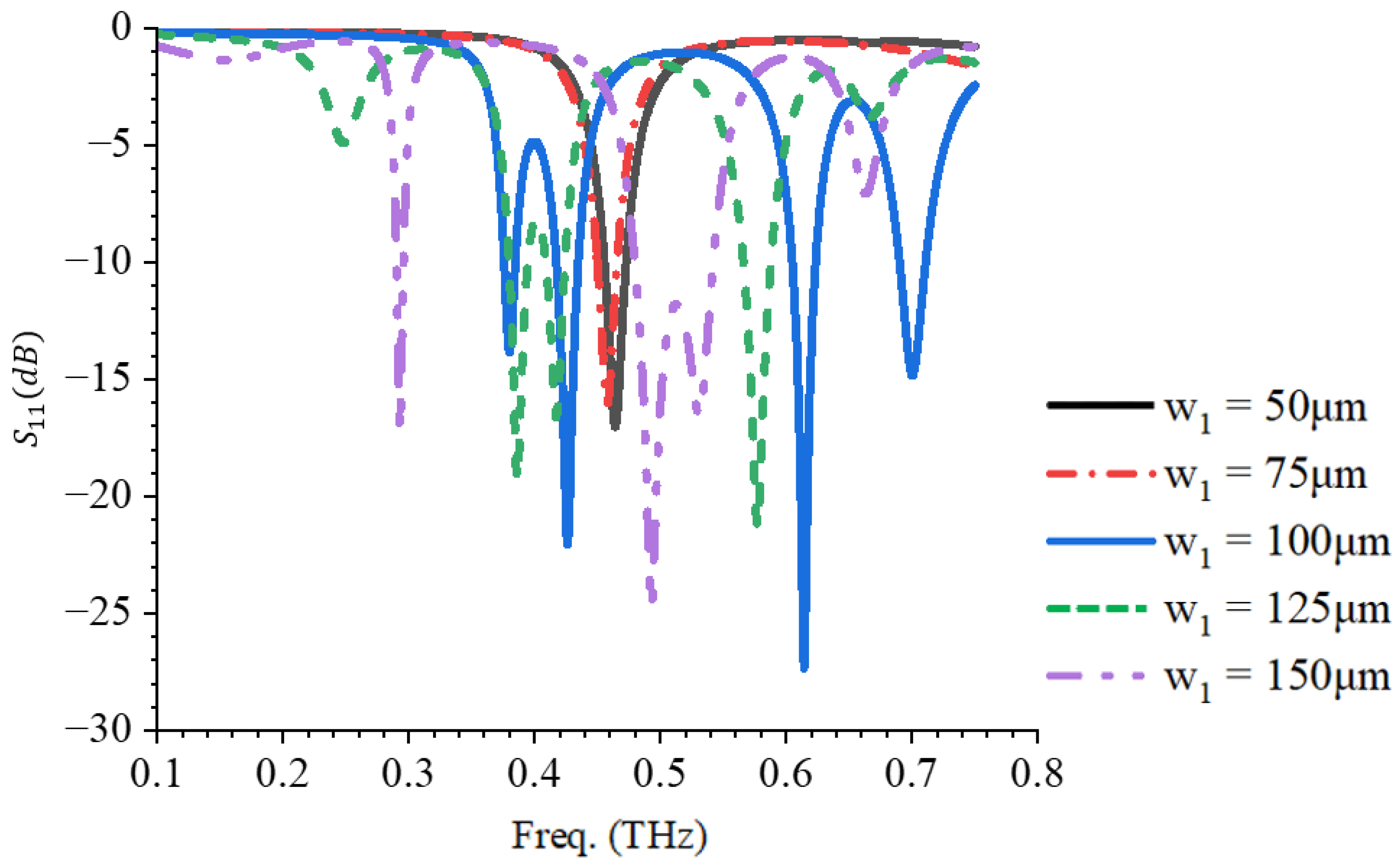
Figure 12 shows the relationship between the change in w 1 and the reflection coefficient. The parameter w 1 has a significant effect on the resonance response of the TPS antenna as shown in Figure 12. For instance, when w 1 is 50   μ m  and   75   μ m , only one resonant frequency is observed, at 0.465 THz and 0.457 THz, respectively. Four resonant frequencies are observed from w 1 = 100   μ m and above. For example, at w 1 = 100   μ m , four resonant frequencies are obtained as shown in Figure 12. Although four resonances are obtained at w 1 = 125   μ m , the reflection coefficient at the fundamental frequency is poor (−5 dB). Also, at w 1 = 150   μ m , the reflection coefficient at 0.7 THz is poor (−7 dB), as shown in Figure 12. Therefore, the optimial value of w 1 is 100   μ m .

4.4. Variational Effect of w s on the Reflection Coefficient

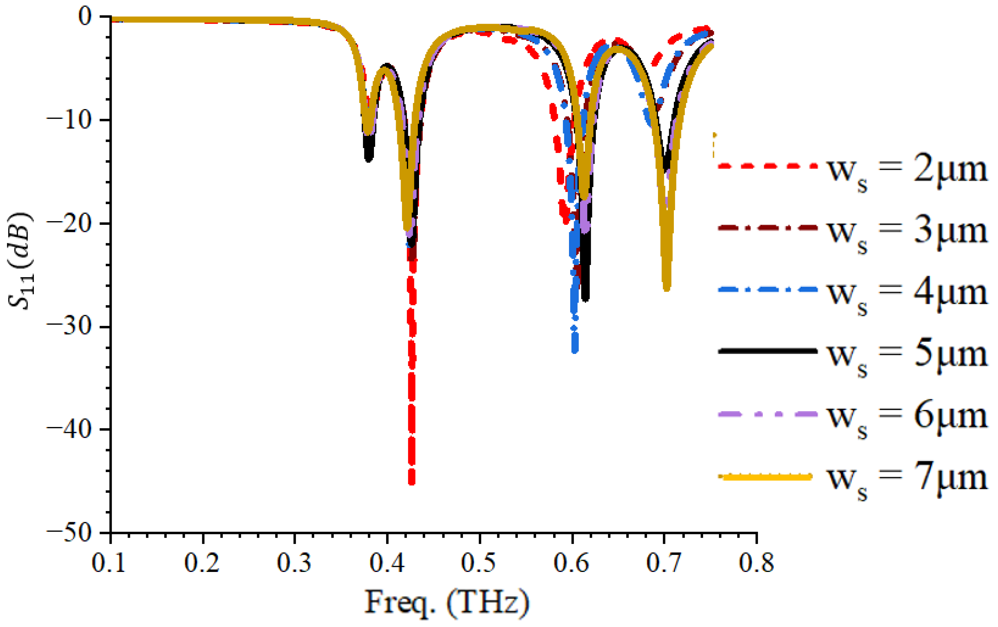
Figure 13 shows the effect of w s on the reflection coefficient response of the TPS antenna. It can be observed that w s has an effect on the reflection coefficient at all resonant frequecies. For instance, a pronounced effect is observed on both the resonant frequency and the reflection coefficient at the fourth band (0.69–0.711 THz), as shown in Figure 13. As w s increases, it can be observed that the reflection coefficient at 0.7 THz reduces. For instance, when w s = 2   μ m , the reflection coefficient is −5.5 dB at 0.66 THz, while when w s = 3   μ m , the reflection coefficient is −8.8 dB at 0.68 THz, as shown in Figure 13. At the third band (0.607–0.623 THz), changes are also observed in the resonant frequency and the reflection coefficient as w s changes. For instance, when w s =   2   μ m , the third resonant frequency is 0.58 THz with an S 11 of −18 dB but, when w s is 3   μ m and 4   μ m , the resonant frequencies are 0.59 THz and 0.6 THz with an S 11 of −20 dB and −26 dB, respectively. Hence, an increase in w s increases the third resonant frequency, while a decrease is observed at the fourth resonant frequency. The effect of w s on a −10 dB bandwidth is evalutated. When w s = 5   μ m , the −10 dB bandwidth is 0.01 (0.3754–0.3854) THz, 0.0176 (0.4179–0.4355) THz, 0.0139 (0.6061–0.6200) THz, and 0.0279 (0.6885–0.7164) THz at the first, second, third, and fourth operating bands, respectively; when w s = 6   μ m , a −10 dB bandwidth of 0.0082 (0.3754–0.3836) THz, 0.0164 (0.4164–0.4328) THz, 0.0159 (0.6061–0.6220) THz, and 0.0246 (0.6885–0.7131) THz at the first, second, third, and fourth operating bands, respectively, is observed. While at a w s of 7   μ m , a −10 dB bandwidth of 0.0065 (0.3754–0.3819) THz, 0.0172 (0.4183–0.4355) THz, 0.0178 (0.6061–0.6239) THz, and 0.0194 (0.6911–0.7105) THz at the first, second, third, and fourth operating bands, respectively, is observed. It can be observed that an increase in w s from 5   μ m to 6   μ m leads to a reduction in the −10 dB bandwidth at the first, second, and fourth operating bands but an increase in the −10 dB bandwidth at the third operating band.

5. Design and Analysis of MIMO Antenna

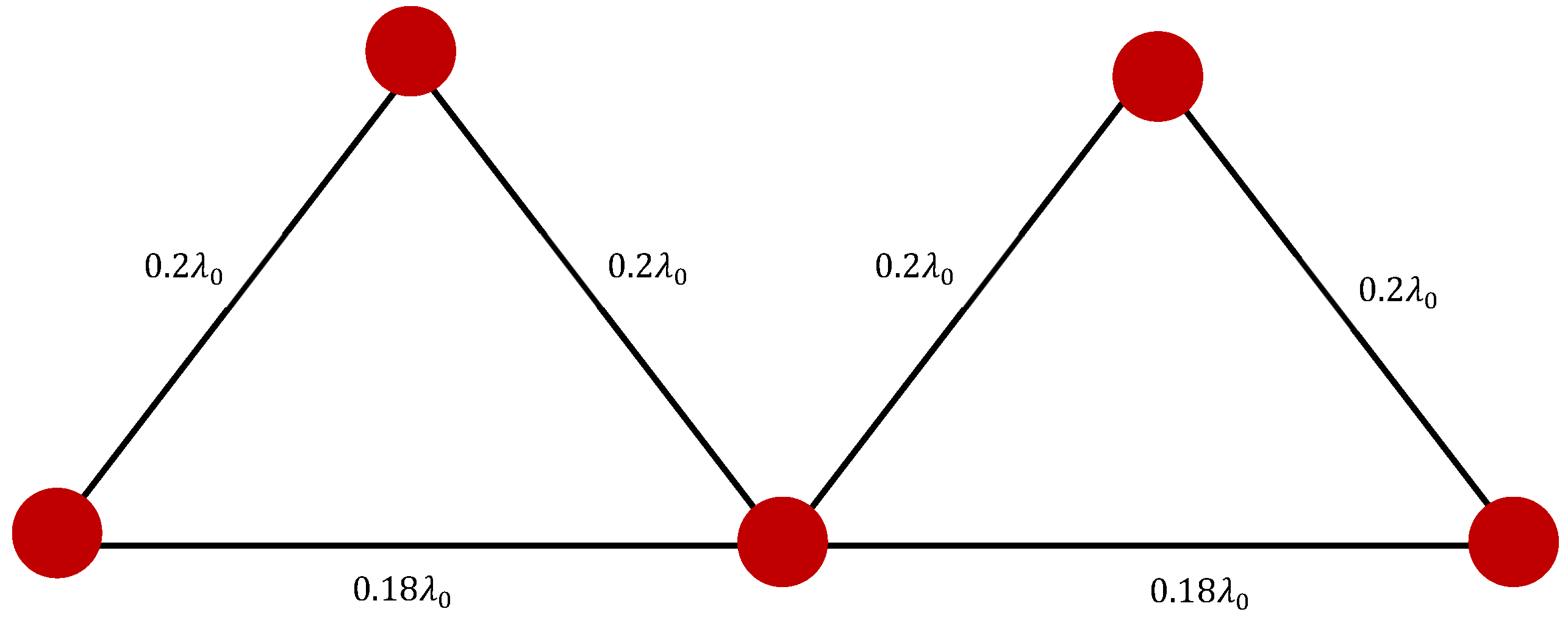
A five-element antenna array is herein designed and investigated. The MIMO antenna configuration employs a compact, non-uniform geometric arrangement characterized by sub-wavelength inter-element spacing and a zig-zag triangular topology as shown in Figure 14. The elements are arranged such that three radiators lie along a horizontal baseline with an inter-element spacing of 0.18 λ 0 , while two additional elements are positioned above the baseline, connected through diagonal separations of 0.2 λ 0 . This geometry forms two adjacent isosceles triangles and departs from conventional linear or uniformly spaced arrays in order to improve MIMO performance in space-constrained and high-frequency systems.
The choice of this topology (dual-triangular arrangement) was made because it strategically positions antenna elements to enhance their directionality and isolation by optimizing the radiation pattern and reducing the mutual coupling. The spatial separation and angular orientation of the triangular clusters minimizes the near-field interactions and correlation between elements, thereby improving isolation and enabling higher spatial multiplexing efficiency, which is critical for MIMO and terahertz communication systems.
From a system-level perspective, the triangular and zig-zag arrangement enhances the MIMO channel capacity by improving the rank and conditioning of the channel matrix. Each antenna element interacts with the propagation environment in a slightly different manner due to its unique position and orientation, leading to reduced redundancy in the received signals. This is particularly important in terahertz and large-scale MIMO systems, where near-field effects dominate and spherical wavefronts must be exploited for spatial multiplexing and user separation [22,23].
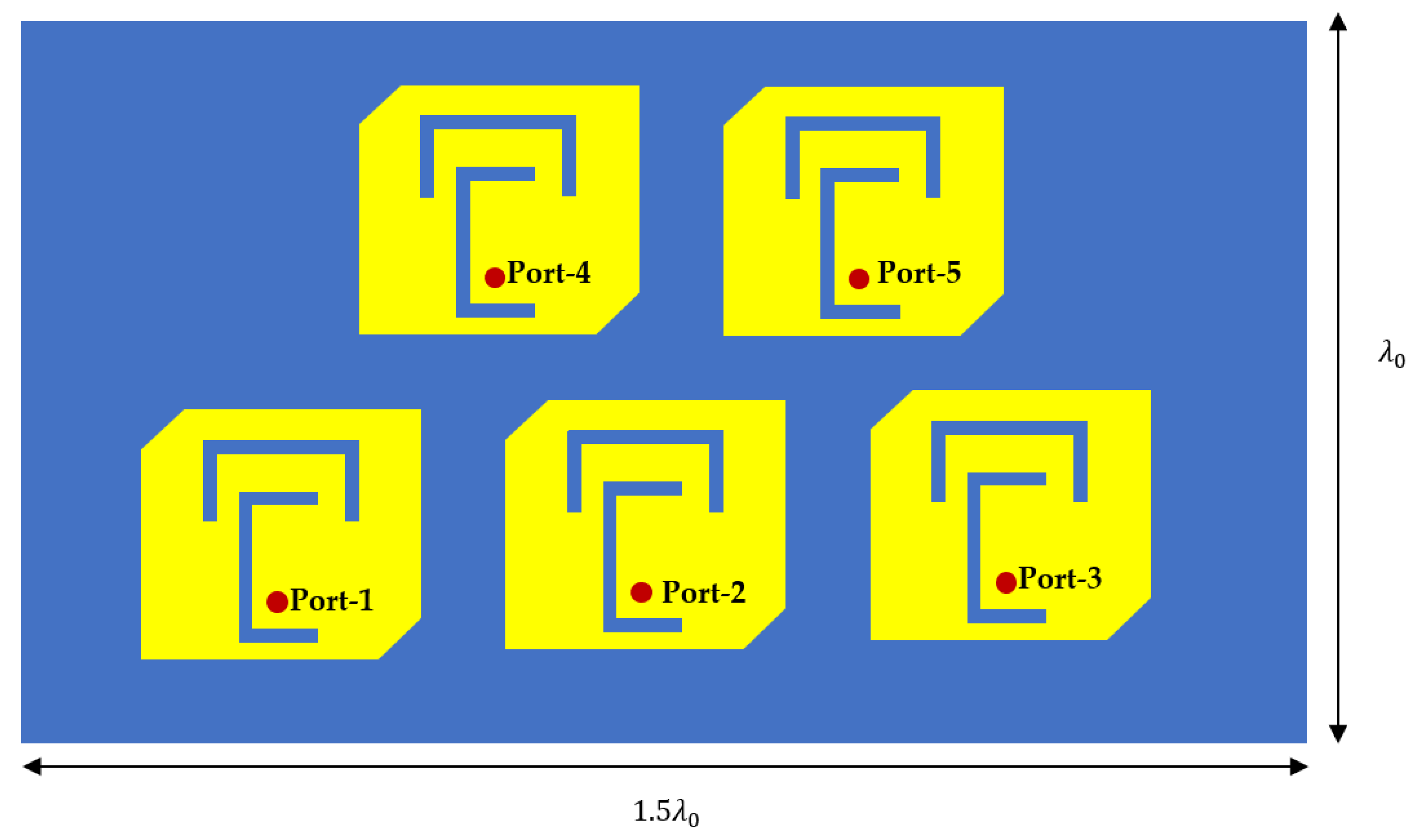
The use of sub-wavelength spacing places the proposed MIMO TSP in the dense MIMO category, which is particularly relevant for terahertz and extremely large-scale MIMO applications where the physical dimensions must be minimized. In such spacing conditions, mutual coupling between neighboring elements is expected to be strong, thereby affecting the input impedance, resonant frequency, and radiation efficiency. However, a non-collinear arrangement of the elements is used to ensure that the coupling is not purely parallel or symmetric, thereby reducing the severity of coupling effects compared to a straight linear array with the same spacing. The footprint dimensioning is shown in Figure 15. The wavelength λ 0 is the fundamental frequency of 0.38   T H z .
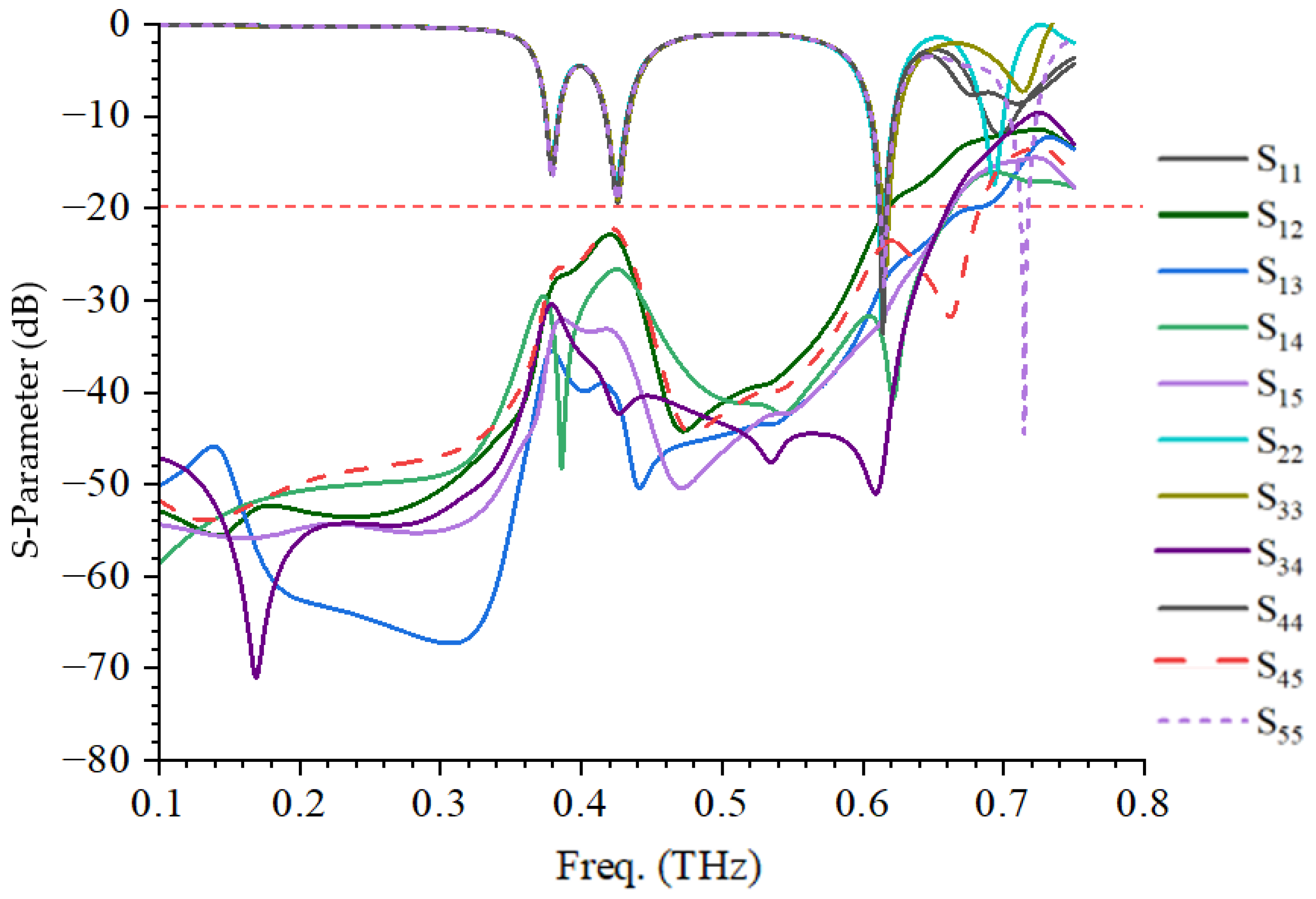
Figure 16 shows the transmission and reflection response of the MIMO configuration. It can be observed that the resonant frequencies are maintained at 0.38 THz, 0.43 THz, 0.61 THz, and 0.7 THz. It can be observed that the isolation at the first three bands is less than −20 dB, while a −10 dB isolation was achieved at 0.7 THz, as shown in Figure 16.
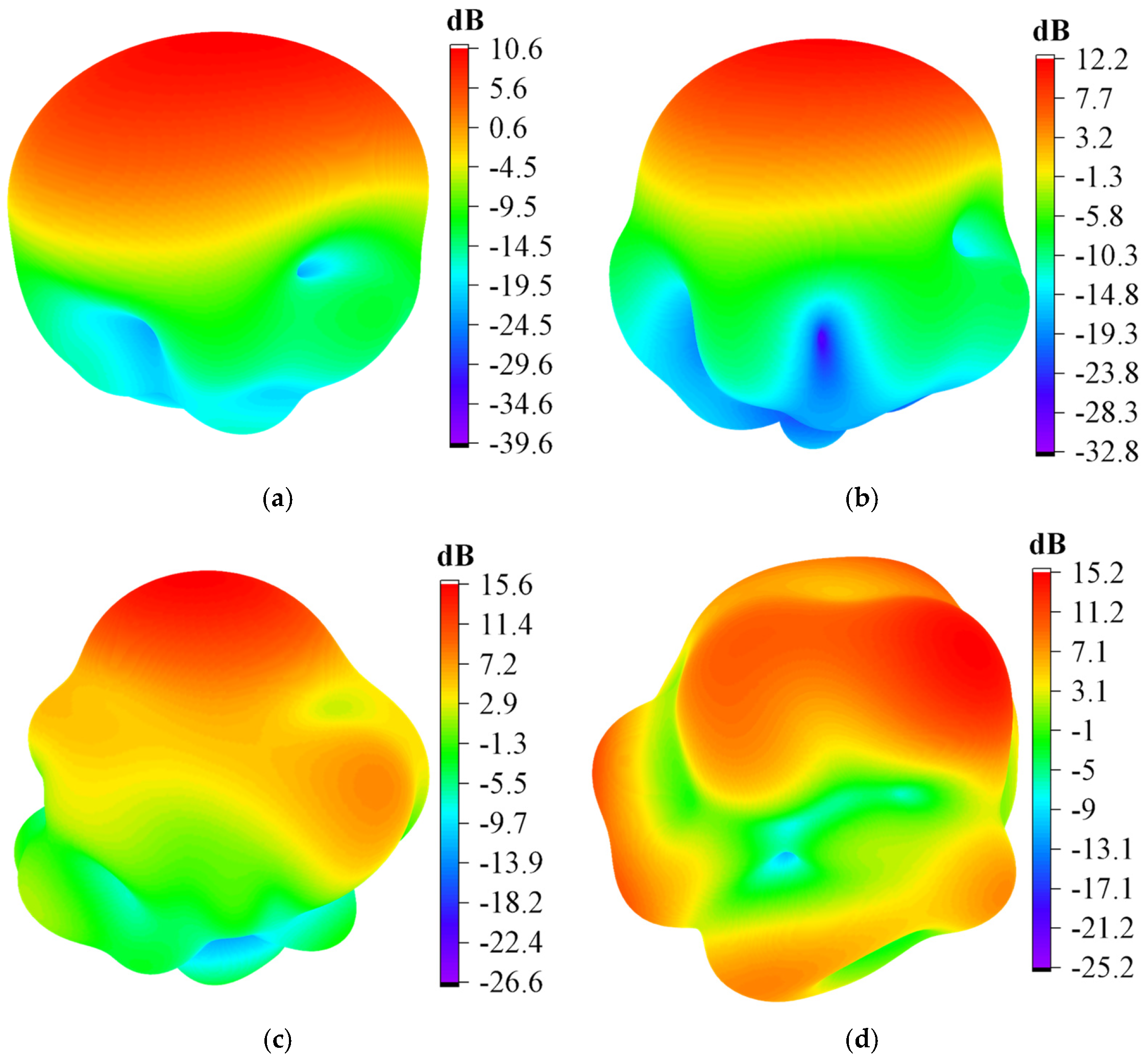
The gain of the TSP MIMO antenna is shown in Figure 17. It can be seen that the gains at 0.38 THz, 0.43 THz, 0.61 THz, and 0.7 THz are 10.6 dB, 12.2 dB, 15.6 dB, and 15.2 dB, respectively.

5.1. Envelope Correlation Coefficient (ECC)

The ECC shows the degree of independence of radiation patterns between any two antennas. It quantifies the degree of correlation between signals received by different antenna elements in a MIMO system. The envelope correlation coefficient ( ρ e ) is the square of the correlation coefficient ( ρ ) . The envelope correlation coefficient between two antennas is 0 if one of the antennas radiates toward the sky and the other toward the ground. The lower the ECC, the better the isolation, which in turn improves the MIMO antenna system as a whole. For MIMO antennas, the ideal ECC value is always smaller than 0.5 [7]. The ECC can be calculated using either Equation (6) or (7) [24,25]. The major difference between the two equations is that the radiation coupling is not accounted for in Equation (6), while Equation (7) accounts for the radiation field.
ρ i j 2 = ρ e i j
ρ e i j = S i i * S i j + S j i * S j j 1 S i i 2 + S j i 2 1 S j j 2 + S i j 2 η r a d i η r a d j 2
ρ e m n = 4 π   F m θ , F n ( θ , ) d Ω 2 4 π   F m ( θ , ) 2   d Ω 4 π   F n ( θ , ) 2   d Ω
where
  F i θ , is the 3D-radiation pattern of the antenna when port i is excited; Ω is the solid angle; ∗ is the Hermitian product operator; and S i j is the coupling between the elements i t h and j t h . The radiation efficiency of the i t h and j t h elements are denoted by η r a d i and η r a d j , respectively.
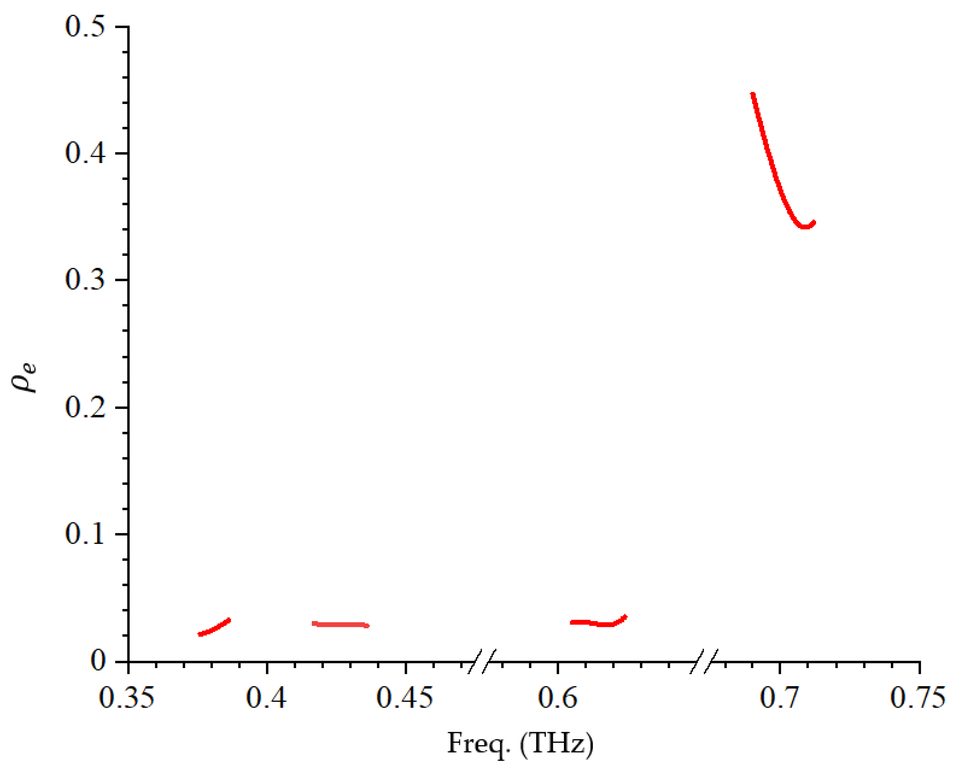
Figure 18 shows the ECC of the TPS MIMO antenna at the operating frequency bands. It can be observed that a low ECC is achieved in the operating bands of the TPS antenna. For instance, the ECC at the first three bands is less than 0.04, as seen in Figure 18. It is worth noting that the peak ECC within the upper band is 0.44, which is still within the acceptable range. This shows that the TPS MIMO antenna demonstrates lower coupling and higher isolation at the operating frequency bands.

5.2. Diversity Gain

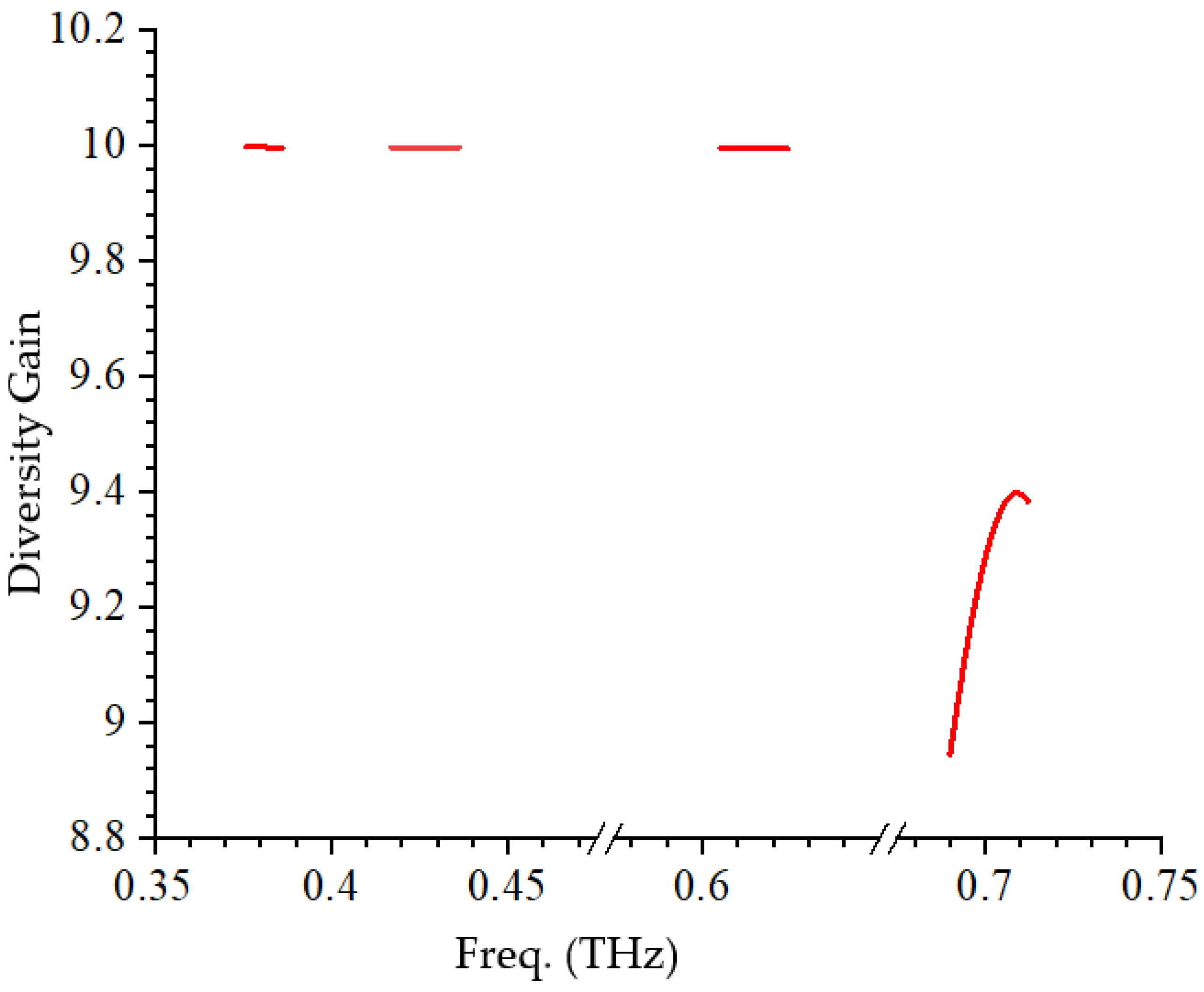
The use of multiple antennas leads to transmission through different channel paths. With uncorrelated signals, the combined received signals would have a higher signal-to-noise ratio and hence a good signal reception. The measure of the effect of diversity on the communication system is called diversity gain (DG). It is estimated using Equation (8) [24].
D G = 10 1 E C C 2
Figure 19 shows the DG of the TPS MIMO antenna. It can be observed that the DG of the TPS antenna is between 9 and 10, as shown in Figure 19. This shows that the TPS MIMO antenna has good diversity gain. Hence, the TPS MIMO antenna is suitable for enhancing reliability and robustness in the face of fading and interference by increasing the SNR, boosting the transmission power with minimal performance loss.

5.3. Mean Effective Gain (MEG)

The MEG is a crucial parameter in the characterization of the performance of MIMO system diversity. This parameter compares the power received by the isotropic antenna to the diversity gain of the antenna in a fading environment. The MEG of an ith element in a MIMO system is determined by using Equation (9) [24,25].
M E G i = 1 2 1 n = 1 N S i n 2
where N is the number of elements in the system.
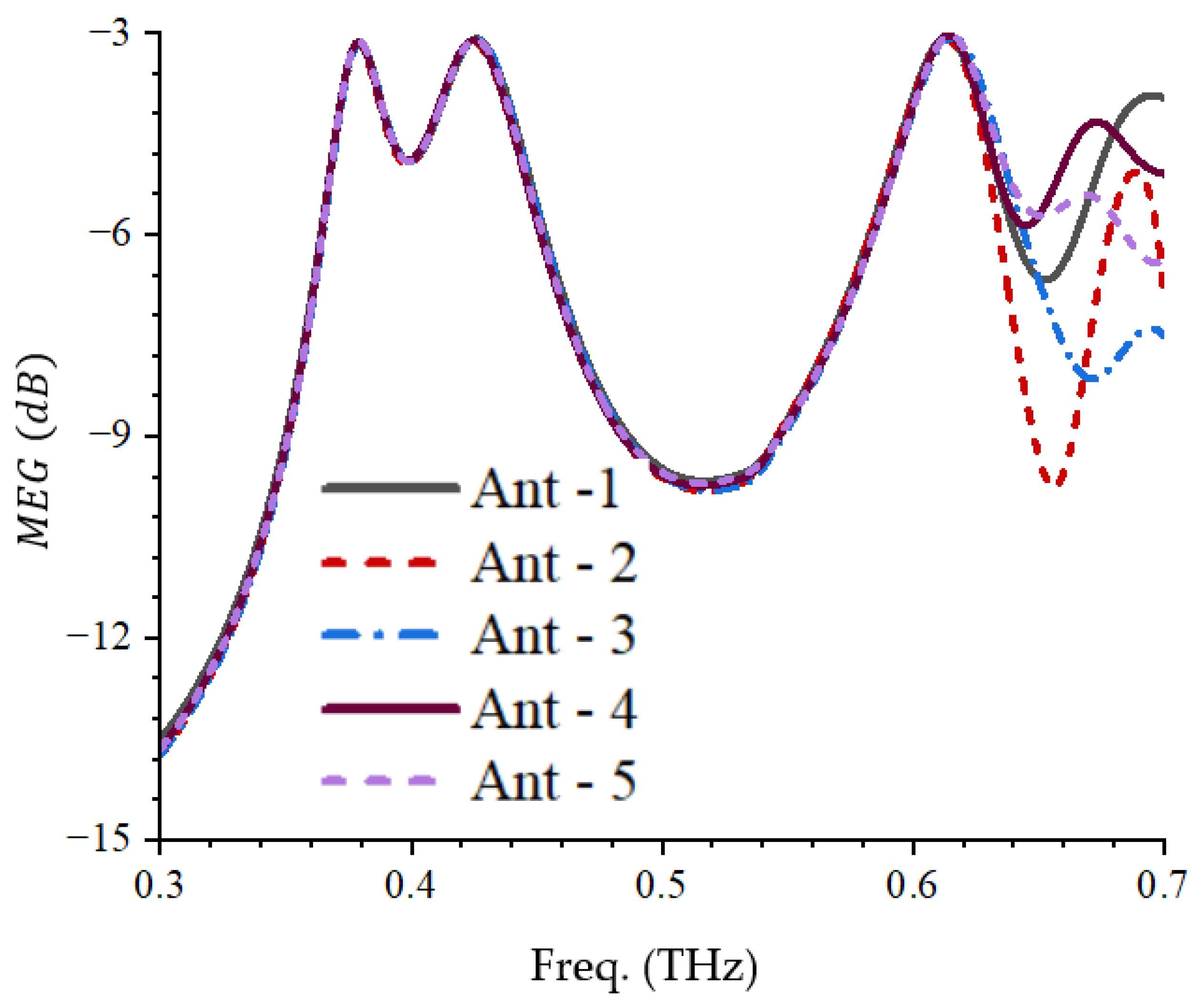
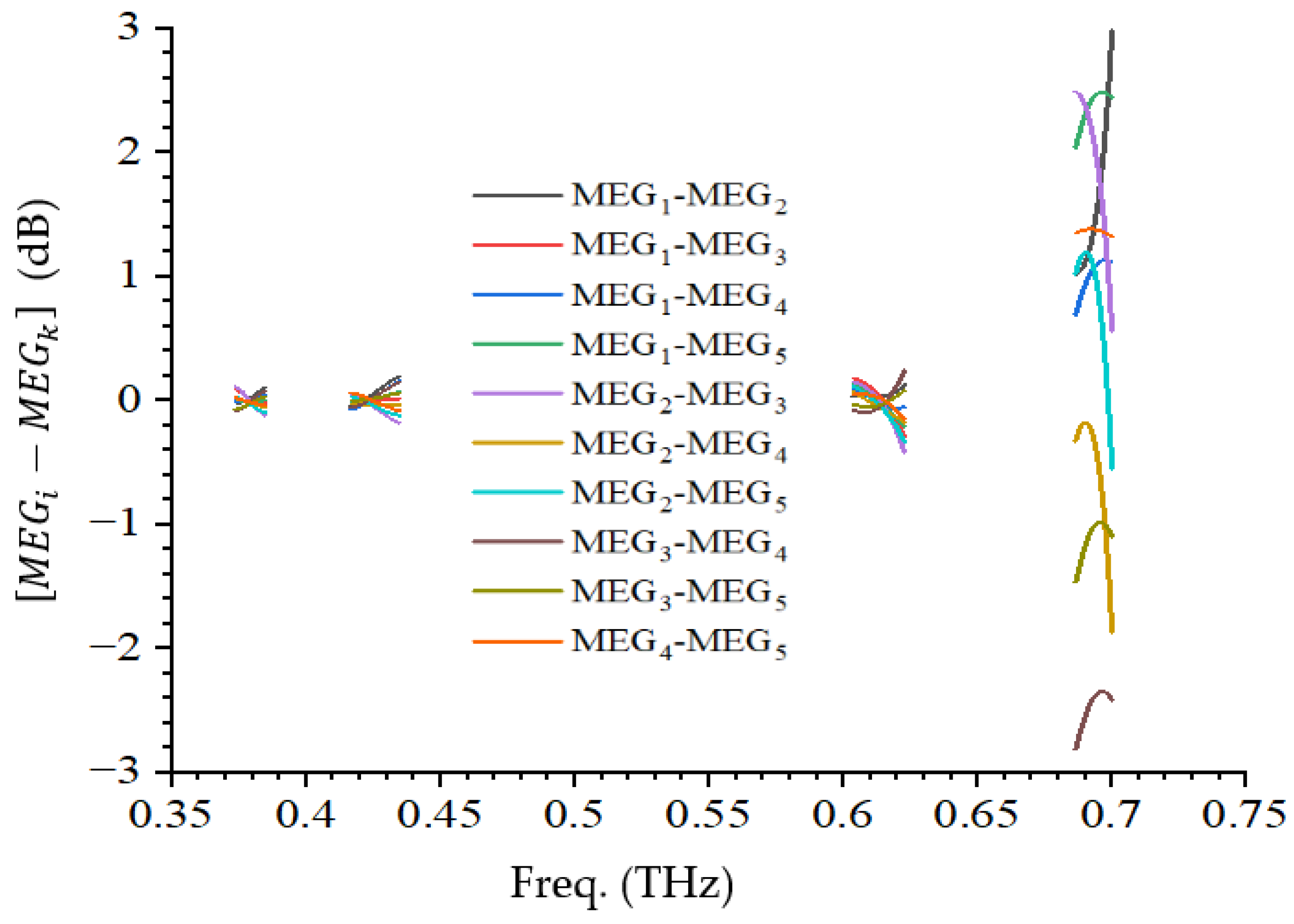
The MIMO system is expected to satisfy Equation (10) [24] at all the operating frequencies where i k ,   1 i 5 , and   1 k 5 . The MEG is evaluated for different values of i and k . Figure 20 shows the MEG of the proposed TSP MIMO antenna. It can be observed that the proposed TSP MIMO antenna meets this criteria in all the operating bands, as shown in Figure 21. For instance, at the first three bands, M E G i M E G k < 0.02   d B, but at the fourth band, M E G i M E G k < 3   d B across the band, as shown in Figure 21. This shows that the proposed TSP antenna is suitable for terahertz MIMO applications.
M E G i M E G k < 3   d B

6. Comparative Analysis

The comparative analysis of the proposed single element TSP antenna and the MIMO configuration is presented in Table 2 and Table 3, respectively. In order to ensure fairness in the comparison, guided wavelength has been used for antenna footprint instead of free space wavelength so as to put into consideration the substrate permittivity because it has effective on the antenna size. It can be observed from Table 2 that the proposed TSP antenna is compact, compared with some of the recent works. It can also be observed that the radiation efficiency of the proposed TSP antenna is better than the antenna reported by the authors in [26] despite its compactness. It is also worth noting that the gain of the proposed TSP antenna is comparatively better than the peak gain reported by the authors in [13,20,26,27,28]. Though the gains of the antennas presented in [29,30,31] are higher than the gain of the TSP antenna proposed in this work; these antennas have a larger footprint than the TSP antenna proposed in this work. Therefore, the use of hybrid slots on a truncated square radiating patch to achieve the quad-band terahertz antenna presented here for the first time shows better performance in terms of its compactness, number of operating bands, radiation efficiency, and gain.
For the MIMO configuration, the proposed TSP MIMO antenna also demonstrated compactness and good performance in terms of its gain and ECC, as observed in Table 3. It is worth noting that, comparing the size of just the two-element and four-element MIMO antenna presented by the authors in [18] and [31], respectively, with the size of the five antenna elements proposed in this work, the proposed TSP antenna is compact, with a better gain. Therefore, it can be observed that the MIMO structural arrangement (an isosceles triangular arrangement), used in this work for the first time in the terahertz band, results in compactness, good isolation, and MIMO gain, compared to recent works in the literature. These analyses show that the proposed TSP antenna and its MIMO configuration are promising candidates for future wireless communication.
Table 2. A comparison of the single-element antenna with existing antennas.
Ref.Size
λ g × λ g @ f l ( T H z )
Substrate@ ε r Number of BandsPeak Eff. (%)Peak Gain
(dB)
[26]3.27 × 3.27@1.0Pyrex@5.2Single784.88
[13]0.63 × 0.63@1.9Silica@3.9Triple>924.75
[32]2.06 × 3.18@0.6Polymide@3.5Dual868.36
[27]2.42 × 2.42@2.27Duriod6010@10.2Single-4.8
[20]0.57 × 0.57@0.29Duriod5880@2.28Single853.1
[29]7.06 × 9.08@0.948Duriod6010@10.2Triple-9
[28]1.06 × 1.06@2.0silica@3.9Single955.02
[30]4.26 × 2.13@0.2Silica@3.9SingleNR7
Proposed
TSP Antenna
0.38 × 0.38@0.38Duriod5880@2.28Quad835.5
Table 3. A comparison of the TSP MIMO antenna with existing antennas.
Ref.Size
λ g × λ g @ f l ( T H z )
Type of BandConductor TypeECCNo of
Elements
TopologyDGPeak Gain
(dB)
[33]2.38 × 1.41@3.1UWBCopper < 0.00001 2Linear 10 12
[31]1.02 × 0.51@0.276SingleGraphene < 0.01 2Linear 10 -
[18]1.04 × 0.98@0.3Singlegraphene and gold 4Planar-6.38
[34]4.5 × 8.62@5.5WBalumina, and silicon 2Linear-9.14
[7]2.53 × 2.53@8.96WBCopper < 0.05 4Planar 10 8.96
Proposed MIMO TSP 2.25 × 1.5@0.38MultibandCopper<0.045Triangle>915.2
UWB: Ultrawideband, WB: Wideband.

7. Conclusions

A compact quad-band terahertz antenna has been presented in this work. The proposed TSP antenna is made up of a truncated square patch with inverted-U-shaped and C-shaped slots. The operating frequencies of the proposed antenna are 0.38 THz, 0.43 THz, 0.61 THz, and 0.7 THz, with a reflection coefficient of −13.8 dB, −22.1 dB, −27.3 dB, and −14.8 dB, a −10 dB impedance bandwidth of 9 GHz, 18 GHz, 18 GHz, and 21 GHz, and a peak gain of 3.3 dB, 4.8 dB, 4.7 dB, and 5.5 dB, respectively. The proposed TPS antenna is validated using a FDTD-based CST simulator and there is a good agreement between the FEM and FDTD resonance responses of the proposed antenna. The dual-triangular MIMO configuration was investigated. The peak gains of the MIMO configuration at the operating frequencies of 0.38 THz, 0.43 THz, 0.61 THz, and 0.7 THz are 10.6 dB, 12.2 dB, 15.6 dB, and 15.2 dB, respectively. The ECC and DG of the proposed MIMO antenna were investigated and are presented. The proposed MIMO antenna demonstrates lower coupling and higher isolation at the operating frequency bands. The comparative analysis shows that the proposed TSP antenna and its MIMO configuration are promising candidates for future wireless communication such as 6G and beyond wireless communication and terahertz imaging.

Author Contributions

Conceptualization, J.O.A., P.K. and D.B.O.K.; methodology, J.O.A., P.K. and D.B.O.K.; software, J.O.A.; validation, J.O.A., P.K.; formal analysis, J.O.A.; investigation, J.O.A.; writing—original draft preparation, J.O.A.; writing—review and editing, P.K. and D.B.O.K. All authors have read and agreed to the published version of the manuscript.

Funding

This research received no external funding.

Data Availability Statement

Please add the corresponding content of this part.Data is contained within the article.

Conflicts of Interest

The authors declare no conflict of interest.

References

  1. Akyildiz, I.F.; Jornet, J.M.; Han, C. Terahertz band: Next frontier for wireless communications. Phys. Commun. 2014, 12, 16–32. [Google Scholar] [CrossRef] [Scilit]
  2. Rappaport, T.S.; Xing, Y.; Kanhere, O.; Ju, S.; Madanayake, A.; Mandal, S.; Alkhateeb, A.; Trichopoulos, G.C. Wireless communications and applications above 100 GHz: Opportunities and challenges for 6g and beyond. IEEE Access 2019, 7, 78729–78757. [Google Scholar] [CrossRef] [Scilit]
  3. Rubani, Q.; Gupta, S.H.; Rajawat, A. A compact MIMO antenna for WBAN operating at Terahertz frequency. Int. J. Light Electron Opt. 2020, 207, 164447. [Google Scholar] [CrossRef] [Scilit]
  4. Kumar, C.; Raghuwanshi, S.K.; Kumar, V. Graphene-based patch antenna array on photonic crystal substrate at terahertz frequency band. J. Electromagn. Waves Appl. 2024, 38, 250–263. [Google Scholar] [CrossRef] [Scilit]
  5. Abolade, J.O. Tri-band bio-inspired terahertz antenna with integrated negative-refractive-index metamaterial for terahertz applications. Next Res. 2024, 1, 100067. [Google Scholar] [CrossRef] [Scilit]
  6. Abolade, J.O. Miniaturized multiband antenna for terahertz applications in wireless body area network. Results Opt. 2023, 10, 100340. [Google Scholar] [CrossRef] [Scilit]
  7. Raghunath, J.; Kumar, P.; Ali, T.; Kumar, P.; Ghouse, P.S.B.; Pathan, S. A Quad-Port Nature-Inspired Lotus-Shaped Wideband Terahertz Antenna for Wireless Applications. J. Sens. Actuator Netw. 2023, 12, 69. [Google Scholar] [CrossRef] [Scilit]
  8. Zhang, X.; Fu, H.; Ma, K.; Yan, N.; Liu, Y.; Mu, Y. Investigation of Channel Parasitic Effect of CMOS Transistor for High Responsivity 2.58 THz Detector Array with Patch Antennas in Chip. IEEE Trans. Terahertz Sci. Technol. 2023, 13, 464–475. [Google Scholar] [CrossRef] [Scilit]
  9. Markelz, A.G.; Mittleman, D.M. Perspective on Terahertz Applications in Bioscience and Biotechnology. ACS Photonics 2022, 9, 1117–1126. [Google Scholar] [CrossRef] [Scilit]
  10. Nissan, U.N.; Singh, G.; Ayokunle, A. Low sidelobe levels Terahertz microstrip antennas for bio-sensing and communications. Sens. Int. 2021, 2, 100097. [Google Scholar] [CrossRef] [Scilit]
  11. Jamshed, M.A.; Nauman, A.; Abbasi, M.A.B.; Kim, S.W. Antenna Selection and Designing for THz Applications: Suitability and Performance Evaluation: A Survey. IEEE Access 2020, 8, 113246–113261. [Google Scholar] [CrossRef] [Scilit]
  12. Abolade, J.O.; Konditi, D.B.O.; Kumar, P.; Olaleru, G. Compact Bio-Inspired Terahertz Ultrawideband Antenna: A Viburnum tinus-Based Approach for 6G and Beyond Applications. J. Sens. Actuator Netw. 2025, 14, 107. [Google Scholar] [CrossRef] [Scilit]
  13. Shalini, M.; Ganesh Madhan, M. Performance predictions of slotted graphene patch antenna for multi-band operation in terahertz regime. Optik 2020, 204, 164223. [Google Scholar]
  14. Das, S.; Mitra, D.; Chaudhuri, S.R.B. Fractal loaded circular patch antenna for super wide band operation in THz frequency region. Optik 2021, 226, 165528. [Google Scholar] [CrossRef] [Scilit]
  15. Sharma, M.K.; Sharma, A. Compact size easily extendable self isolated multi-port multi-band antenna for future 5G high band and sub-THz band applications. Opt. Quantum Electron. 2022, 55, 146. [Google Scholar] [CrossRef] [Scilit]
  16. Larsson, E.G.; Edfors, O.; Tufvesson, F.; Marzetta, T.L. Massive MIMO for next generation wireless systems. IEEE Commun. Mag. 2014, 52, 186–195. [Google Scholar] [CrossRef] [Scilit]
  17. Rajarajeshwari, K.C.; Saravanakumar, N. A high-performance dual-element slotted THz antenna with enhanced MIMO metrics for 5G/6G applications. Wirel. Netw. 2025, 31, 4215–4226. [Google Scholar] [CrossRef] [Scilit]
  18. Pandey, G.K.; Rao, T.; Mondal, S. Design and Analysis of Graphene based Octagonal Short-angular Circular Patch MIMO Antenna for Terahertz Communications. In Proceedings of the 2nd International Conference on Intelligent Technologies, Hubli, India, 24–26 June 2022; pp. 1–4. [Google Scholar] [CrossRef] [Scilit]
  19. Mohanty, A.; Sahu, S. A Micro 4-port THz MIMO antenna for nano communication networks. Photonics Nanostruct.—Fundam. Appl. 2023, 53, 101092. [Google Scholar] [CrossRef] [Scilit]
  20. Abolade, J.O.; Konditi, D.B. Integrated Artificial Magnetic Conductor Minkowski Island fractal terahertz antenna (AMC-MIFA) for future Communications. Results Opt. 2025, 21, 100921. [Google Scholar] [CrossRef] [Scilit]
  21. Ruan, X.; Chan, C.H. Terahertz free-space dielectric property measurements using time- and frequency-domain setups. Int. J. RF Microw. Comput.-Aided Eng. 2019, 29, e21839. [Google Scholar] [CrossRef] [Scilit]
  22. Guo, S.; Qu, K. Beamspace Modulation for Near Field Capacity Improvement in XL-MIMO Communications. IEEE Wirel. Commun. Lett. 2023, 12, 1434–1438. [Google Scholar] [CrossRef] [Scilit]
  23. Irshad, A.; Kosasih, A.; Björnson, E.; Sanguinetti, L. Optimal Dual-Polarized Planar Arrays for Massive Capacity over Point-to-Point MIMO Channels. IEEE Trans. Wirel. Commun. 2024, 23, 19350–19364. [Google Scholar] [CrossRef] [Scilit]
  24. Aboualalaa, M.; Mansour, I. Dual-Band End-Fire Four-Element MIMO Antenna Array Using Split-Ring Structure for mm-Wave 5G Applications. IEEE Access 2023, 11, 57383–57390. [Google Scholar] [CrossRef] [Scilit]
  25. Sharawi, M.S. Printed multi-band MIMO antenna systems and their performance metrics [wireless corner]. IEEE Antennas Propag. Mag. 2013, 55, 218–232. [Google Scholar] [CrossRef] [Scilit]
  26. Efazat, S.S.; Basiri, R.; Makki, S.V.A.-D. The gain enhancement of a graphene loaded reconfigurable antenna with non-uniform metasurface in terahertz band. Optik 2019, 183, 1179–1190. [Google Scholar] [CrossRef] [Scilit]
  27. Rubani, Q.; Gupta, S.H.; Kumar, A. Design and analysis of circular patch antenna for WBAN at terahertz frequency. Optik 2019, 185, 529–536. [Google Scholar] [CrossRef] [Scilit]
  28. Shalini, M.; Madhan, M.G. A compact antenna structure for circular polarized terahertz radiation. Optik 2021, 231, 166393. [Google Scholar] [CrossRef] [Scilit]
  29. Vijay, S.; Ali, J.; Yupapin, P.; Ahmad, B.H.; Ray, K. A triband EBG loaded microstrip fractal antenna for THz application. Sci. Iran. 2023, 30, 207–217. [Google Scholar] [CrossRef] [Scilit]
  30. Jin, J.; Cheng, Z.; Chen, J.; Zhou, T.; Wu, C.; Xu, C. Reconfigurable terahertz Vivaldi antenna based on a hybrid graphene-metal structure. Int. J. RF Microw. Comput.-Aided Eng. 2020, 30, e22175. [Google Scholar] [CrossRef] [Scilit]
  31. Babu, K.V.; Das, S.; Varshney, G.; Sree, G.N.J.; Madhav, B.T.P. A micro-scaled graphene-based tree-shaped wideband printed MIMO antenna for terahertz applications. J. Comput. Electron. 2022, 21, 289–303. [Google Scholar] [CrossRef] [Scilit]
  32. Amraoui, Y.; Halkhams, I.; El Alami, R.; Jamil, M.O.; Qjidaa, H. Terahertz dual-band antenna design with improved performances using FSS-based metasurface concept for wireless applications. Sci. Afr. 2025, 27, e02566. [Google Scholar] [CrossRef] [Scilit]
  33. Singhal, S. Four arm windmill shaped superwideband terahertz MIMO fractal antenna. Optik 2020, 219, 165093. [Google Scholar] [CrossRef] [Scilit]
  34. Yadav, R.; Parmar, A.; Malviya, L.; Nitnaware, D. Ultra Wideband MIMO Antenna Design with High Isolation for THz Application. In Proceedings of the IEEE 11th International Conference on Communication Systems and Network Technologies, Indore, India, 23–24 April 2022; pp. 26–30. [Google Scholar] [CrossRef] [Scilit]
Figure 1. TSP design evolution (a) square patch; (b) truncated patch; (c) truncated patch with inverted U-shaped slot; (d) proposed antenna.
Technologies 14 00059 g001
Figure 2. TSP antenna dimensioning.
Technologies 14 00059 g002
Figure 3. The reflection coefficient response of the TPS antenna design stages (legend I is the response of the antenna in Figure 1a, legend II is the response of the antenna in Figure 1b, legend III is the response of the antenna in Figure 1c, and legend IV is the response of the antenna in Figure 1d).
Technologies 14 00059 g003
Figure 4. A FDTD-based CST model of the proposed TPS antenna.
Technologies 14 00059 g004
Figure 5. The S11 responses of the FDTD- and FEM-based models of the proposed TPS antenna.
Technologies 14 00059 g005
Figure 6. TSP antenna 3D gain patterns at (a) 0.38 THz; (b) 0.43 THz; (c) 0.61 THz; and (d) 0.7 THz.
Technologies 14 00059 g006
Figure 7. TSP antenna radiation patterns at (a) 0.38 THz; (b) 0.43 THz; (c) 0.61 THz; and (d) 0.7 THz.
Technologies 14 00059 g007
Figure 8. TPS antenna efficiency.
Technologies 14 00059 g008
Figure 9. TPS antenna current distribution at (a) 0.38 THz; (b) 0.43 THz; (c) 0.61 THz; and (d) 0.7 THz.
Technologies 14 00059 g009
Figure 10. Effect of l1 on the reflection coefficient.
Technologies 14 00059 g010
Figure 11. Effect of wt on the reflection coefficient.
Technologies 14 00059 g011
Figure 12. Effect of w1 on the reflection coefficient.
Technologies 14 00059 g012
Figure 13. Effect of ws on the reflection coefficient.
Technologies 14 00059 g013
Figure 14. 5 × 5 TSP antenna dual-triangular MIMO configuration.
Technologies 14 00059 g014
Figure 15. 5 × 5 TSP antenna MIMO configuration footprint.
Technologies 14 00059 g015
Figure 16. MIMO TSP antenna S-parameter response.
Technologies 14 00059 g016
Figure 17. The 3D gain of the TSP MIMO antenna at (a) 0.38 THz; (b) 0.43 THz; (c) 0.61 THz; and (d) 0.7 THz.
Technologies 14 00059 g017
Figure 18. The ECC of the TSP MIMO antenna.
Technologies 14 00059 g018
Figure 19. The DG of the TSP MIMO antenna.
Technologies 14 00059 g019
Figure 20. The MEG of the proposed TSP MIMO antenna.
Technologies 14 00059 g020
Figure 21. ( M E G i M E G k ) of the proposed TSP MIMO antenna.
Technologies 14 00059 g021
Table 1. Proposed TSP antenna parameterization.
P a r a m e t e r l g w g w 3 w 2 w t w 1 w p w s l t l p l 1 l 2 l 3 l 4
V a l u e ( μ m ) 400 400 67.5 100 15 100 200 5 15 200 50 67 50 25
Disclaimer/Publisher’s Note: The statements, opinions and data contained in all publications are solely those of the individual author(s) and contributor(s) and not of MDPI and/or the editor(s). MDPI and/or the editor(s) disclaim responsibility for any injury to people or property resulting from any ideas, methods, instructions or products referred to in the content.