Article

A Combined Mirror–EMG Robot-Assisted Therapy System for Lower Limb Rehabilitation

by
Florin Covaciu
1,
Bogdan Gherman
1,*,
Calin Vaida
1,
Adrian Pisla
1,
Paul Tucan
1,
Andrei Caprariu
1 and
Doina Pisla
1,2,*
1
Research Center for Industrial Robots Simulation and Testing—CESTER, Faculty of Industrial Engineering, Robotics and Production Management, Technical University of Cluj-Napoca, 400114 Cluj-Napoca, Romania
2
Technical Sciences Academy of Romania, B-dul Dacia, 26, 030167 Bucharest, Romania
*
Authors to whom correspondence should be addressed.
Technologies 2025, 13(6), 227; https://doi.org/10.3390/technologies13060227
Submission received: 21 February 2025 / Revised: 20 May 2025 / Accepted: 27 May 2025 / Published: 3 June 2025

Abstract

:
This paper presents the development and initial evaluation of a novel protocol for robot-assisted lower limb rehabilitation. It integrates dual-modal patient interaction, employing mirror therapy and an auto-adaptive EMG-driven control system, designed to enhance lower limb rehabilitation in patients with hemiparesis impairments. The system features a robotic platform specifically engineered for lower limb rehabilitation, which operates in conjunction with a virtual reality (VR) environment. This immersive environment comprises a digital twin of the robotic system alongside a human avatar representing the patient and a set of virtual targets to be reached by the patient. To implement mirror therapy, the proposed protocol utilizes a set of inertial sensors placed on the patient’s healthy limb to capture real-time motion data. The auto-adaptive protocol takes as input the EMG signals (if any) from sensors placed on the impaired limb and performs the required motions to reach the virtual targets in the VR application. By synchronizing the motions of the healthy limb with the digital twin in the VR space, the system aims to promote neuroplasticity, reduce pain perception, and encourage engagement in rehabilitation exercises. Initial laboratory trials demonstrate promising outcomes in terms of improved motor function and subject motivation. This research not only underscores the efficacy of integrating robotics and virtual reality in rehabilitation but also opens avenues for advanced personalized therapies in clinical settings. Future work will investigate the efficiency of the proposed solution using patients, thus demonstrating clinical usability, and explore the potential integration of additional feedback mechanisms to further enhance the therapeutic efficacy of the system.

1. Introduction

Over the past four decades, stroke has been the leading cause of mortality and disability globally, affecting millions of lives and imposing a significant burden on health systems [1]. The consequences of a stroke include paralysis or muscle weakness, sensory, motor and cognitive problems, speech and swallowing difficulties, and a reduced ability to participate in social and community activities. These effects can lead to a significant decrease in the quality of life, affecting both the independence and the emotional state of the affected person. In addition, personality changes and emotional disorders, such as depression and anxiety, may also occur [2,3]. The main approach of stroke rehabilitation has traditionally been physical therapies, but over time, technology has advanced, and new methods have emerged to improve the rehabilitation process, such as robot-assisted intervention, EMG-based intervention, virtual reality-based intervention, and mirror therapy [4,5]. Literature analysis has revealed an innovative robotic device used for shoulder rehabilitation of patients after stroke [6]. Hsu et al. conducted a study in which they suggested that incorporating mirror therapy into a virtual reality system may have a superior effect on motor rehabilitation for stroke patients [7]. Gebreheat et al. summarize the results of eight experimental studies conducted between 2019 and 2023. The review concludes that immersive virtual reality mirror therapy (IVRMT) is a safe and feasible method for upper limb rehabilitation after stroke, offering increased patient engagement and significant motor improvements [8]. A portable system used in rehabilitation therapy has been developed, based on virtual reality, functional electrical stimulation, and a training device [9]. This system is intended to support a home-based therapy process in people with reduced dorsiflexion capacity. A study has been conducted [10], aiming to compare the perceived usability of two feedback-based stroke therapies, namely conventional MT and VR MT. The improvement of physical function in stroke survivors largely depends on the application of structured programs based on repetitive, functional, and personalized repetitive exercise, which contribute significantly to the recovery of mobility and daily activities [11]. Rehabilitation using robotic systems has proven to be effective in providing intensive, repetitive therapy tailored to the individual needs of patients with neurological disorders [12]. Tohanean et al. undertook research to evaluate the effectiveness of a parallel robot for motor rehabilitation of the shoulder, elbow, and wrist of a patient with motor deficit [13]. MT is an innovative method that has become increasingly popular due to its simplicity, low cost, and ease of application [14]. The method was originally described by Ramachandran et al., who found that the use of mirrors can influence the perception of the phantom limb in people who have had their limbs amputated [15]. Mirror therapy training can stimulate a brain network that supports both attention and action monitoring [16]. Miclaus et al. analyzed the effectiveness of combining VR with mirror therapy for lower limb rehabilitation in post-stroke patients. The study demonstrates that this innovative approach contributes significantly to improving mobility, balance, and motor control. Through engaging visual simulations and real-time feedback, patients can reactivate their impaired neural connections. The results suggest that integrating these technologies can increase the effectiveness of traditional therapy and speed up the recovery process [17]. Yang et al. proposed a robotic rehabilitation system that combines mirror therapy and surface electromyographic signal analysis (sEMG) to assess real-time active patient engagement. The system allows personalized training and stimulates functional recovery through synchronized bilateral movements. The results indicate significant improvements in patient engagement and therapy effectiveness, although its wide application is limited by the complexity and cost of the equipment [18]. Nizamis et al. provided a comprehensive review of emerging robotic technologies used in personalized rehabilitation. The review highlights the integration of artificial intelligence, neural interfaces, and sensory feedback-based control to improve the accuracy and efficiency of therapy. The authors also highlight current challenges related to standardization, cost, and clinical acceptability, suggesting future directions for optimizing these innovative solutions [19]. Zhang et al. proposed an intelligent VR-assisted ankle rehabilitation system that utilizes a recurrent convolutional neural network (ConvGRU) for therapeutic decision-making. The model analyzes real-time movement data to assess patient progress and tailor rehabilitation exercises in a personalized way. The study shows that this approach increases the accuracy in monitoring recovery and the effectiveness of interventions by automatically adapting to individual needs [20]. Fan et al. investigated how self-action perception in VR activates and integrates the mirror neuron system with the sensor–motors cortex. The study, based on functional imaging, showed that observing one’s own movements in a virtual environment can generate brain activations like those of real movements, stimulating networks involved in motor learning and empathy. These results support the use of virtual reality as an effective tool in neuro-motor rehabilitation therapies [21].
The current paper presents an innovative lower limb rehabilitation protocol for bedridden patients, combining a parallel robot and a VR application with a dual-modal patient interaction to provide mirror therapy and an auto-adaptive EMG-driven control system. The mirror therapy approach employs inertial sensors to classify the patient’s motions using neural networks, while EMG sensors are used to detect the patient’s intention to move different lower limb segments according to the training task set in the VR application. This innovative approach has important benefits, aiming to improve the rehabilitation outcomes through a highly immersive environment developed using virtual reality coupled with the synchronous motion of both legs using sensors and the robotic system. The therapy is directed by a physician through a graphical interface that controls the VR simulation, while the patient performs the same movements with their healthy limb. These motions are then replicated by the robot for the impaired limb, enhancing the therapeutic experience and promoting recovery. The rest of the paper is organized as follows: Section 2 presents the main hardware and software components of the system and their interaction, and Section 3 the most important outcomes of the proposed research activity, while Section 4 presents some conclusions and future work.

2. Materials and Methods

Figure 1 presents the general architecture of the proposed robot-assisted rehabilitation system, which underlines the development of a novel medical protocol. With the patient placed in a supine position on a hospital bed, and with the impaired limb attached to the robot, 3 inertial measurement unit (IMU) sensors are attached to the patient’s healthy leg: on the thigh, on the calf, and on the foot, which are used to measure the position and orientation of the leg. The therapist can control the VR application and the parallel robot for lower limb rehabilitation using the user interface. The muscle condition is monitored using an electromyography (EMG) sensor attached to the patient’s impaired leg. A VR headset placed on his head is used to implement the VR application, showing a virtual patient placed on the digital twin of the robot. The therapist connects to the VR application on the right monitor in Figure 1 and initiates the data transmission of the IMU sensors and the EMG sensor on the user interface. Once the parallel robot is activated, the therapist instructs the patient to move their healthy limb using a virtual avatar. The patient can see exactly how to execute the movements through the avatar’s example, which enhances their understanding and improves their ability to perform the exercises correctly. Additionally, interacting with a virtual avatar in an immersive environment can be captivating and motivating, thus contributing to greater adherence to the rehabilitation program. While the patient moves his healthy leg, the artificial intelligence program performs a classification of the recorded motions into the 5 types of rehabilitation exercises that the parallel robot can perform, namely hip flexion–extension and adduction–abduction, knee flexion, ankle flexion–dorsiflexion and eversion–inversion. The motion parameters are further sent to the experimental parallel robot to perform movements of the patient’s leg undergoing physical treatment. The motion classification is performed using the data from the IMU sensors transmitted via the Wi-Fi protocol.

2.1. The Proposed Rehabilitation Protocol

The LegUp lower limb rehabilitation system employs an auto-adaptive control mechanism implemented through a VR application, which includes automatic fatigue detection during training exercises. In the VR interface, virtual targets are represented as colored bars that patients must reach with different segments of their lower limb, as illustrated in Figure 24. The therapist establishes the initial position (height) of these targets and sets the baseline and threshold for EMG sensors to determine fatigue limits, as well as the number of repetitions for each baseline. The LegUp robot guides the patient’s lower limb to reach the proposed target based on the detected EMG signal. If the signal parameters exceed the baseline values within a predefined time window, the patient successfully reaches the virtual target while the LegUp moves the lower limb accordingly, performing several repetitions. To motivate the patient, the baseline can be incrementally increased, and the target’s position adjusted to provide positive visual feedback. If the patient fails to reach the baseline, the protocol initiates a fatigue check. The complete medical protocol is detailed in Figure 2.
The protocol automatically detects if a drop in the EMG signal parameters indicate patient’s fatigue. The two considered and tracked parameters of the EMG signal are the median frequency and the RMS (Root Mean Square) amplitude of the signal. Figure 3a illustrates the algorithm used to determine and track the median frequency of the EMG signal. Following signal acquisition and sampling at 1 GHz, it is segmented into 2 s windows with 50% overlapping for continuity and smooth analysis. A Hamming function has been applied to reduce the spectral leakage before performing the Fast Fourier Transform. The Periodogram used to estimate the Power Spectral Density is computed as follows:
P f i = 1 N f s X f i 2
where P f i is the PSD at frequency f i , X f represents the FFT for the considered signal window, N is the number of points in the current FFT, and fs is the sampling frequency. The PSD estimates are normalized across all windowed segments for improved reliability. The total PSD estimates are computed as
P = i = 1 N P f i
The cumulative power is
P C i = j = 1 i P f j
Which is normalized:
P C n o r m i = P C i P
The median frequency f m e d of the EMG signal is selected for the values of the P C n o r m i that fulfill the condition
P C n o r m i > 0.5
As the f m e d shifts downwards for a preset value (i.e., 10) in a row with at least 20%, a fatigue state of the patient is declared.
The other tracked parameter of the EMG signal to detect the patient’s fatigue is the RMS amplitude, shown in Figure 3b, as
R M S = 1 n i = 1 n x i 2
where x i are the EMG signal samples in each window. Similarly, an increased value of the RMS (beyond 30%) from the baseline usually indicates fatigue. In both cases, the decision is to take a break from the training exercise.

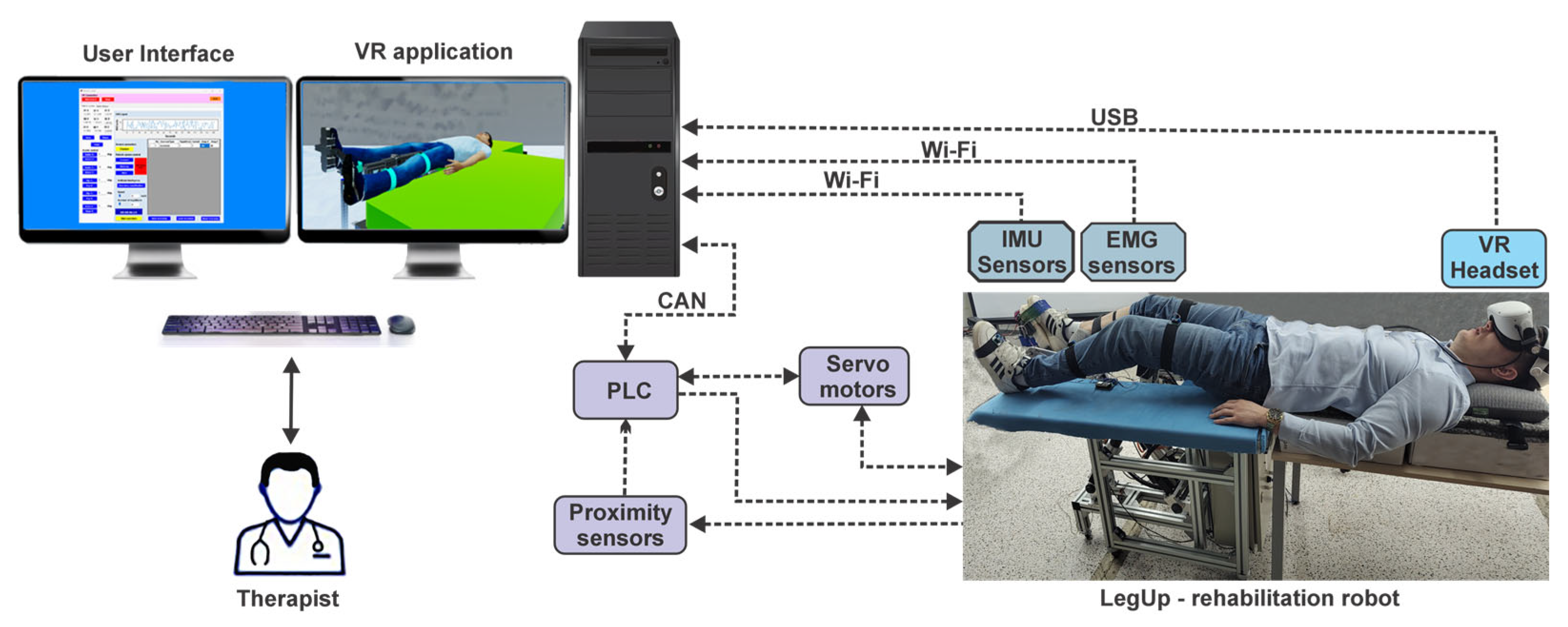
2.2. The Main Elements of the System and Their Interconnectivity

The block diagram in Figure 4 shows the interconnection of the logical components of the control system. Three IMU sensors, model BNO055 from Bosch (Bosch Sensortec, Bucuresti, Romania), are used to obtain the orientation of the patient’s leg, while the patient’s muscle state is monitored using an EMG sensor, model EN0240 from DFRobot (DFROBOT, Timisoara, Romania). The sensor data are sent to the C# application via the Wi-Fi protocol. The C# application takes the data from the IMU sensors and sends it to the user interface and to the artificial intelligence program through a Python 3.12.4 script, while the data received from the EMG sensor are displayed in real time on the user interface for interpretation. Communication between the C# and the VR application is performed via the TCP/IP protocol, and the corresponding user interface is displayed using two monitors and a VR headset (model Oculus 2). Other protocols used in interoperability include HTTP REST API or WebSocket. The advantages of using TCP/IP over HTTP REST API are related to speed, customization, and suitability for real-time applications, also being easier to configure than WebSocket. It also ensures data verification and retransmission in case of losses, and through this protocol, multiple devices can be connected simultaneously, providing good speed and efficiency for data transfers.
The Wi-Fi protocol has some limitations that have been accounted for in the application. Continuous transmission of data from sensors to the C# application over Wi-Fi protocol can lead to network overload and hinder data transfer, especially in the case of high transmission frequency. To optimize this communication and reduce unnecessary traffic, the algorithm responsible for sending the data implements a mechanism to check the values coming from the sensors. In this way, data are only sent to the C# application when there has been a change from previous values.
Figure 4 presents the sensory system used to monitor the healthy leg motions of the patient and the muscles activity.
The sensor’s data are retrieved using a device (Figure 5a) developed using the ESP32 microcontroller development board(Espressif Systems, Bucuresti, Romania) [22], which runs the Arduino program. The ESP32 microcontroller proved to be powerful enough to take data from the EMG sensor and IMU sensors and send it to the C# application on the computer at a good speed, making it acceptable in a rehabilitation system. It works at a frequency of 240 MHz, with a dual core, and can send up to 150 Mbps in Wi-Fi 802.11 b/g/n protocol. Data transmission is at a frequency of 50 ms. The data from the sensors can be acquired and sent further via the Wi-Fi protocol to the C# application. The device in Figure 5a contains the following elements:
  • 1—ESP32 microcontroller development board, which contains the following specifications:
    -
    240 MHz microcontroller, dual-core—Tensilica LX6 (Espressif Systems, Bucuresti, Romania);
    -
    520 KB SRAM memory;
    -
    16 MB flash memory;
    -
    Wi-Fi: 802.11 b/g/n (802.11n up to 150 Mbps);
    -
    Bluetooth: Bluetooth v4.2 BR/EDR and BLE;
  • 2—power supply: 5 V DC;
  • 3—connecting the EMG sensor;
  • 4—connecting IMU sensors;
  • 5—power supply for IMU sensors: 3.3 V DC;
Figure 5. (a) Device used in transmitting and receiving data from sensors. (b) IMU sensor and (c) EMG sensor. (1) ESP32 microcontroller. (2) power supply. (3) connecting the EMG sensor. (4) connecting IMU sensors. (5) power supply for IMU sensors.
Technologies 13 00227 g005
Figure 5b presents the IMU BNO055 [23] sensor wearable board, consisting of the following elements:
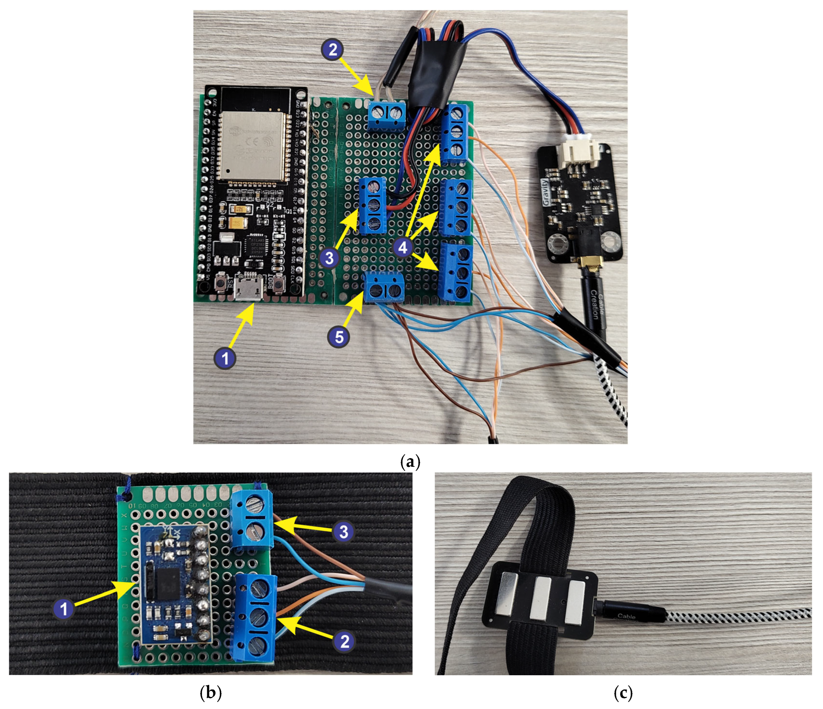
  • 1—absolute orientation sensor—IMU BNO055, having the following characteristics:
    -
    built in nine-axis sensor and MCU resources;
    -
    Communication mode: Standard IIC/serial communication protocol;
    -
    absolute orientation (Euler Vector, 100 Hz)—three-axis orientation data based on a 360° sphere;
    -
    Angular velocity vector (100 Hz)—three axes for “rotational speed” in rad/s;
    -
    Acceleration vector (100 Hz)—three axes for acceleration (gravity + linear motion) in m/s2;
    -
    Magnetic field strength vector (20 Hz)—three axes for magnetic field strength detecting in microTesla (μT);
    -
    Linear acceleration vector (100 Hz)—three axes for linear acceleration (acceleration minus gravity) in m/s2;
    -
    Vector for gravity (100 Hz)—three axes for gravitational acceleration in m/s2.
  • 2—IMU sensor connection jacks to the ESP32 microcontroller development board;
  • 3—power supply connectors for IMU sensors.
Figure 5c presents the EMG sensor [24], built by DFRobot and OYMotion (DFROBOT, Timisoara, Romania). It integrates a filtering and an amplified circuit for the analog signal, which strength depends on the muscle activity.

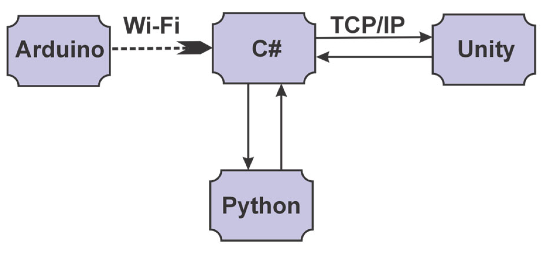
2.3. Software Application Development

The software application includes programs implemented in three programming languages as follows: Arduino (2.2.1), C# (12), and Python (3.12.4). The application implemented in the Arduino language is loaded onto the ESP32 development board and used to retrieve data from the IMU and the EMG sensor. The data must be encoded in the format accepted by the C# application. According to the developed communication protocol between the Arduino and the C# applications, data packages are sent only if a variation in the sensors signal is recorded (by the Arduino program). The script implemented in Python processes the data retrieved from the IMU sensors to be used in the artificial intelligence algorithm. The C# programming language is used both to implement the user interface and to develop the VR application. The software application architecture showing the communication between programs is presented in Figure 6.

2.4. C# Software Application

All the functionalities offered by the software application developed using C#, Arduino, and Unity are illustrated in the use case diagram [25] in Figure 7, which consists of the following elements:
  • 13 use cases that specify the functionality of the software application: 7 cases associated with the application implemented in the C# programming language, 3 use cases associated with the Arduino script, and 3 cases associated with the Unity virtual reality application;
  • 4 actors: the human user of the software application (the therapist), the Python classifier, the parallel robot, and the EMG and IMU sensors;
  • 8 association relationships between actor and use cases;
  • 6 dependency relationships between use cases.
Figure 7. UML use case diagram.
Technologies 13 00227 g007
Analyzing the 7 specific functionalities of the C# application represented by the use case diagram, 6 classes were identified, designed, and implemented to meet the proposed specifications. The class diagram, represented in Figure 8, presents the 6 classes together with the relationships between them, as well as the predefined packages used from the .Net Framework [26]. The 6 classes are characterized by the following meanings:
  • The ExercisesGUI class, derived from the Panel class, allows the therapist to interact with the application’s graphical interface, control the robotic structure, and interact with the virtual reality application;
  • The HistoryGUI class, derived from the Panel class, allows the therapist to monitor the patient’s progress.
  • The UnityConnection class allows connections to be made using sockets between the application implemented in C# and the VR application implemented in Unity by using 3 classes from the System.Net.Sockets package;
  • The ArduinoConnection class enables the connections between the application implemented in C# and the Arduino script by using the System.Net.Sockets package;
  • The RoboticStructureConnection class enables the connections between the application implemented in C# and the parallel robot.
The MainGUI class, derived from the Form class, represents the main class of the C# application consisting of an object of the ExercisesGUI class, an object of the HistoryGUI class, an object of the UnityConnection class, an object of the RoboticStructureConnection class, and an object of the ArduinoConnection class according to the composition relationships represented in the diagram.
User Interface. The robotic rehabilitation system is controlled and monitored through a user interface, which consists of three menus: the Robotic system control menu, the Sessions history menu, and EMG Adaptive control.
Figure 8. UML class diagram.
Technologies 13 00227 g008
The Robotic system control menu, through which the virtual reality application and the parallel robotic rehabilitation system are controlled, is illustrated in Figure 9. This menu includes the following controls:
  • For the “Connect” button in Figure 9, (1) is used to initiate a connection via the TCP/IP protocol between the user interface and the virtual reality application.
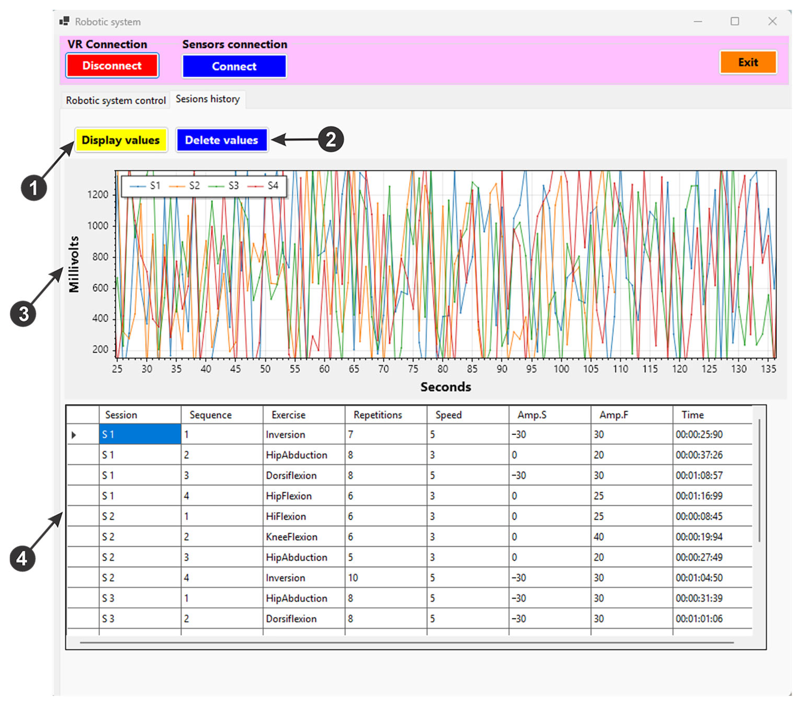
  • For the “Connect” button in Figure 9, (2) initiates the connection between the user interface, the device created to acquire the signals of the IMU sensors and the EMG sensor, using the ESP32 microcontroller development board via the Wi-Fi protocol. It also stores the current position of the sensors to be used as reference during the training exercises within the mirror therapy. Once the connection is created, data are sent from the three IMU sensors (for the X, Y, and Z axes) and displayed on the user interface (Figure 9, (3)). These data are saved in an excel file via the “Save” button (Figure 9, (4)) and can be deleted by pressing the “Clear” button (Figure 9, (4)). Pressing the “Pause” button (Figure 9, (4)) these data are no longer sent to the excel file to be saved. The EMG signal is displayed on the user interface (Figure 9, (5)).
  • For the “Connect” button in Figure 9, (6), is used to initiate the control of the rehabilitation parallel robot. The “Home” button performs the homing procedure of the robot, while the “Start” button (Figure 9, (6)) drives the robot to the starting position, before the actual training exercises begin. The “Emergency Stop” button (Figure 9, (6)) can be used in case of emergency, cutting off the power and thus stopping the robotic system.
  • By pressing the “Exercises classification” button (Figure 9, (7)), the artificial intelligence algorithm performs a classification of the healthy limb motions using the data received from the IMU sensors.
  • When pressing the “Start exercises” button (Figure 9, (8)), a timer measures the duration of an exercise session, and the robotic rehabilitation system performs the rehabilitation exercises by following the movements of the patient’s healthy leg. It also saves the EMG signal performed in a session in an excel file.
  • Using the buttons in the “Avatar control” field (Figure 9, (9)), the virtual patient’ leg motion (human avatar) is controlled, thus being able to perform various rehabilitation exercises at the hip, knee, and ankle level.
  • The rehabilitation exercises in a single session are displayed in a table (Figure 9, (10)), where the type of exercise, the number of repetitions of the exercise, the speed level at which the exercise is performed, and the start and end amplitude can be monitored.
  • The speed and number of repetitions of the rehabilitation exercise can be set using the two sliders in Figure 9, (11).
  • The user interface also enables saving the exercise session in an excel file by pressing the “Save Exercises” button (Figure 9, (12)). Loading the saved exercise session is performed via the “Load Exercises” button (Figure 9, (12)) and resetting the exercise session by pressing the “Reset Exercises” button.
Figure 9. User interface: Robotic system control.
Technologies 13 00227 g009
Through the Sessions history menu (Figure 10), an analysis of the patient’s progress over time is performed by accessing the data recording of each exercise session. The Sessions history menu can be used to assess the patient’s progress by monitoring muscle activity (Figure 10, (3)). Also, through this menu, the table in Figure 10, (4) shows the recorded data, providing a complete picture of the patient’s progress. It enables the adaptation of the desired rehabilitation program in order to meet the patient’s specific needs. To assess the consistency and frequency of the rehabilitation exercises, the table shows the number of completed sessions and the sequence in which they were performed, providing a broader perspective on the patterns. A detailed description of each type of performed exercise is provided, including the name of the exercise and the exact number of repetitions performed for each exercise. To ensure that the movements are performed at an appropriate pace, the speed of execution of the exercise is also monitored, thus minimizing the risk of injury. The amplitude of the exercise reflects the patient’s range of motion, highlighting their mobility and flexibility.
The EMG Adaptive Control menu, used to perform rehabilitation exercises based on adaptive EMG control, is illustrated in Figure 11. The following main commands are available:
To start the rehabilitation process, the user has to press the ‘Start’ button (Figure 11, (1)). After activating this function, two bars (Figure 24a) are displayed in the virtual reality application, one red and one blue. At the same time, a graph (Figure 11, (2)) showing the real-time EMG signal and a display area (Figure 11, (3)) indicating the current status of the EMG signal are started.
In order to actually start the rehabilitation exercises, the user selects the desired exercise type (Figure 11, (4)). Based on this selection, the two bars in the VR application will automatically reposition themselves according to the chosen exercise type (Figure 24b). Subsequently, by means of the buttons on the interface, the user will control the healthy lower limb of the virtual patient, thus executing the specific movements of the exercise. In parallel, the values recorded by the IMU sensors can also be visualized on the GUI (Figure 11, (5)).
The moment the virtual avatar’s lower limbs touch the two bars, the interface signals a collision state (Figure 11, (6)), thus providing additional visual feedback. The progress made in the rehabilitation process is visually represented by a progress bar (Figure 11, (7)), which reflects the level reached in the exercise.
Figure 11. User interface: EMG Adaptive control.
Technologies 13 00227 g011

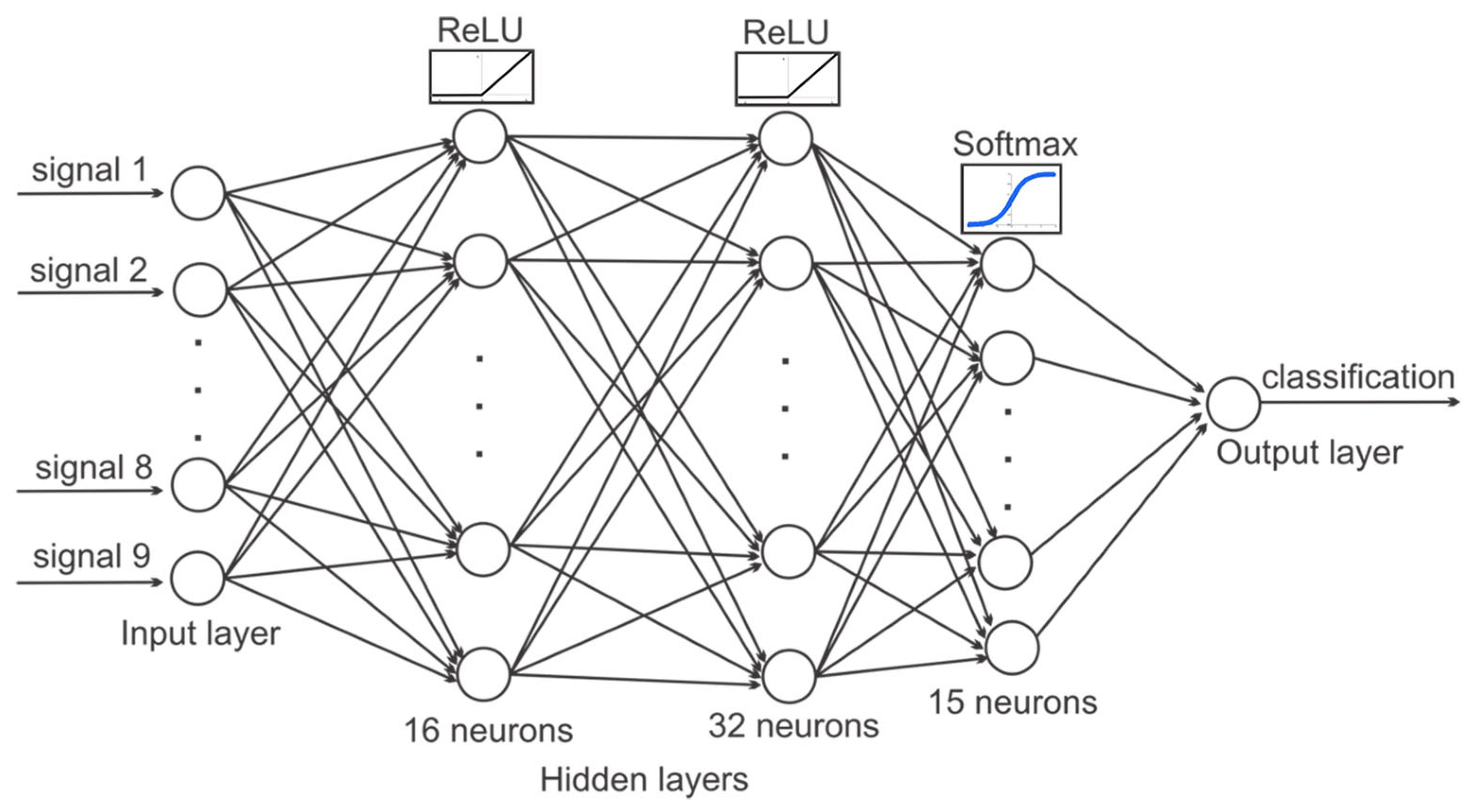
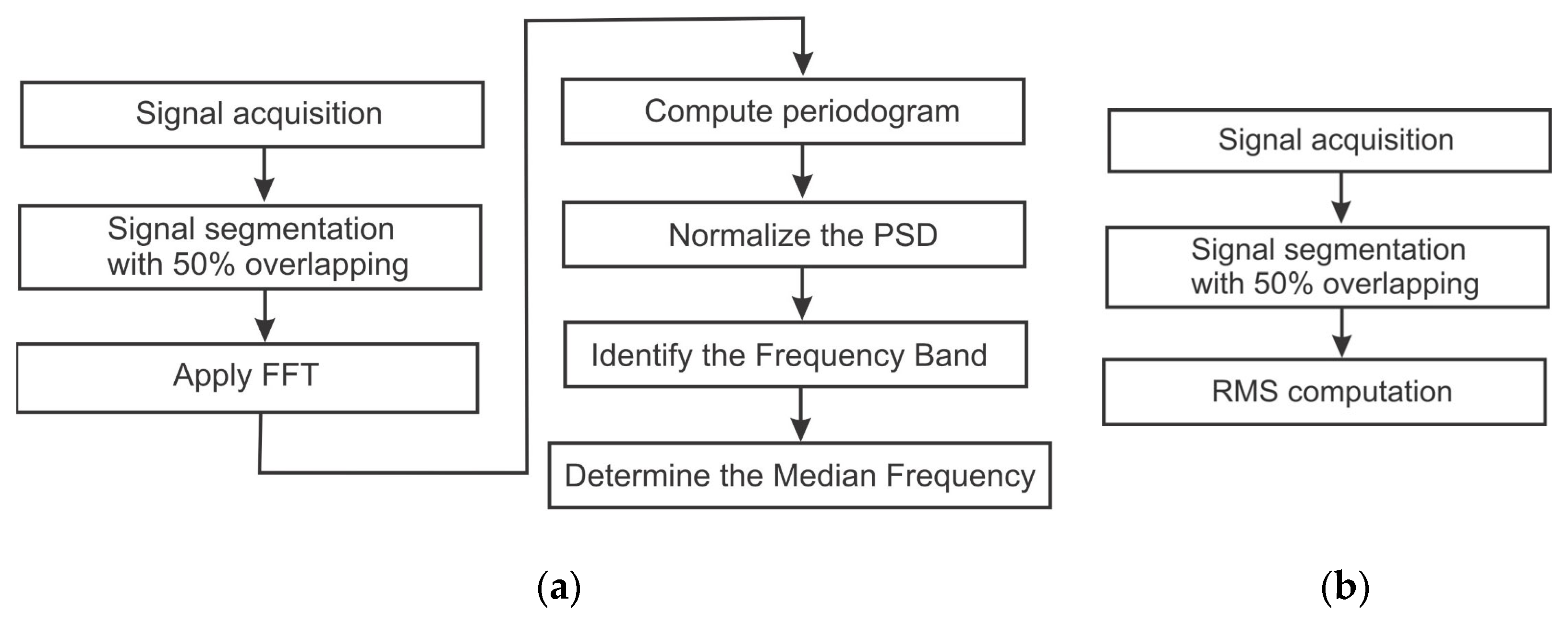
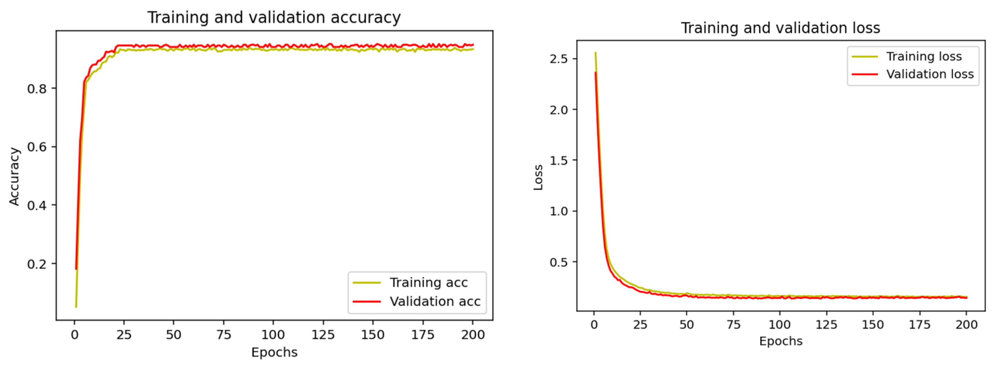
2.5. Keras-Based Artificial Intelligence Used in the Classification of Rehabilitation Exercises

The classification of the rehabilitation exercises performed by the robot is achieved by a multilayer perceptron (MLP) neural network developed through the Anaconda user interface in the Spyder integrated development environment [27] using Python.
The MLP artificial neural network consists of several layers of neurons, as follows:
  • The first layer is the input layer that receives the initial data;
  • The middle layer is hidden, and it processes the data through neurons by applying mathematical functions;
  • The last one is the output layer, which produces the final result of the neural network.
Each neuron in a layer is connected to the neurons in the next layer by links with specific weights that indicate how much one neuron influences the other. The weights are adjusted during the network training process to reduce the difference between the desired and the obtained result.
Five libraries were used to implement the MLP in Figure 12, as follows:
Tensorflow is an open-source library developed by Google for artificial intelligence; Keras is an open-source neural network library, written in Python, that is used to simplify the creation and training of deep learning models; Pandas is an open-source library for data manipulation and analysis, written in Python; MatPlotLib is an open-source library for data visualization in Python, used to create graphs; Sklearn is an open-source library for machine learning in Python that offers a wide range of machine learning algorithms for tasks such as classification and regression.
Figure 12 presents the architecture of the used neural network classification of the rehabilitation exercises. The parameters of an artificial neural network play a crucial role in its effectiveness, influencing both performance and generalization ability. Because networks with multiple layers or a large number of neurons can learn complex representations but present the risk of overtraining if there is not enough data, the following parameters were chosen: value 3 for the number of hidden layers, value 16 for the number of neurons on the first hidden layer, value 32 for the number of neurons on the second hidden layer, and value 15 for the number of neurons on the last hidden layer. For the parameter relating to the number of training epochs, the value 200 was used, because a large number of epochs allows the network to learn better but can lead to overtraining. The network training process includes the use of the “relu” activation function for the first two hidden layers and the “softmax” activation function for the last hidden layer. Performance was evaluated using a test set representing 25% of the data used to train and evaluate the neural network. After the neural network was trained for 200 epochs, the accuracy and losses can be seen in Figure 13.
Figure 12. The neural network architecture. ReLu (black line)—is activation function for the first two hidden layers. Softmax (blue line)—is activation function for the last hidden layer.
Technologies 13 00227 g012

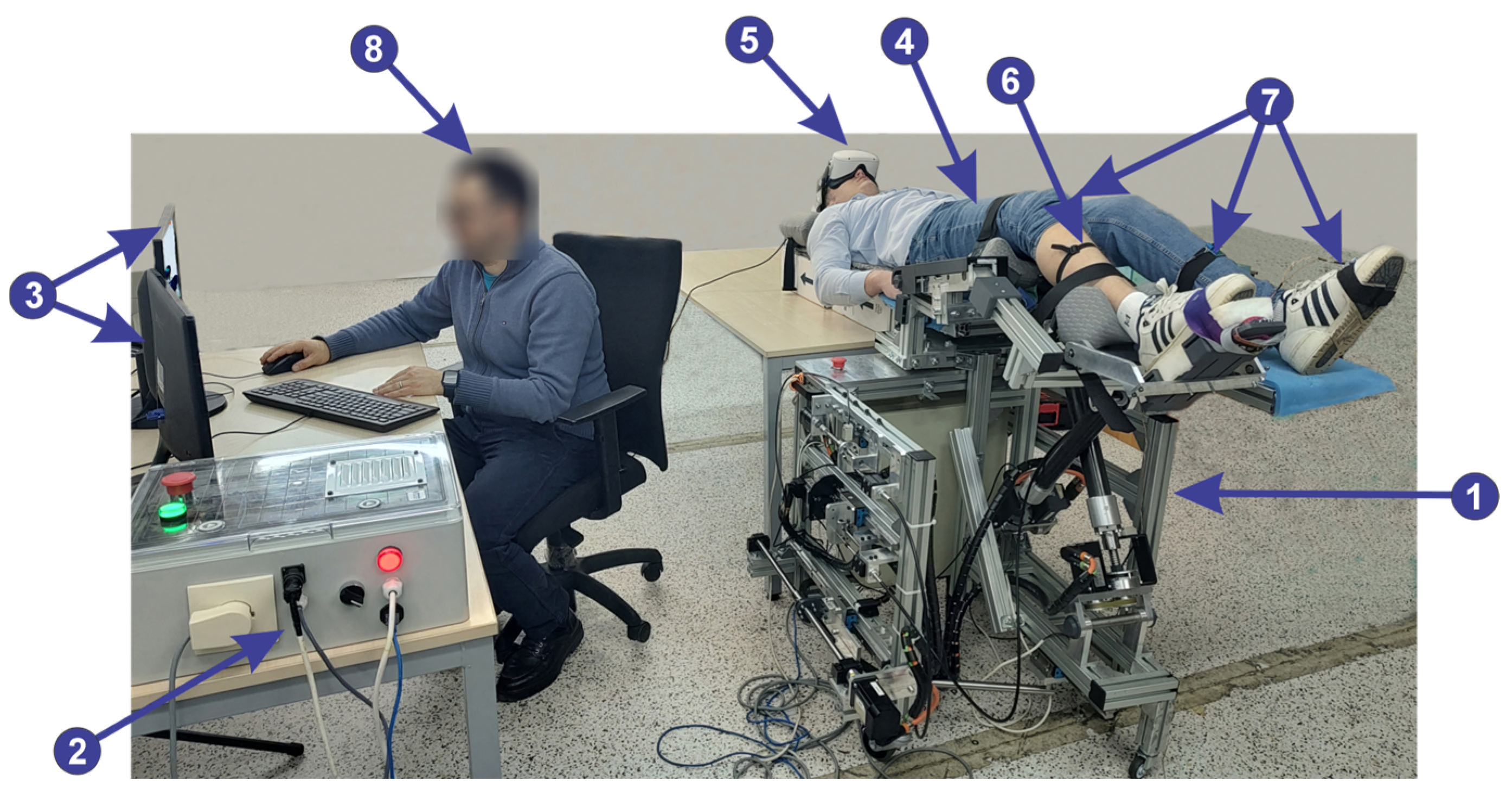
2.6. The Lower Limb Rehabilitation Parallel Robot

The need for diversified rehabilitation systems has driven researchers to create innovative and cost-effective robotic solutions designed to support people from different social backgrounds, focusing on various stages of the rehabilitation process [28,29,30,31]. The proposed parallel robot [32] helps patients with various neuromotor disabilities through spatial rehabilitation of the lower limbs, targeting the major joints: hip, knee, and ankle [33]. The LegUp robot is designed for the rehabilitation of patients with lower limb impairments who are unable to stand due to various conditions. It addresses patients in the acute stage of a stroke, when other classical architectures are unusable since the patients are unable to stand. As opposed to the 1 DOF mechanical architectures suitable for bedridden patients, LegUp has two anchors for increased control of the knee. Thus, LegUp is specifically utilized for bedridden patients, with rehabilitation sessions conducted in either a supine or slightly inclined position.
Figure 14 shows the kinematic scheme of the experimental parallel robot. It has two modules, namely a hip–knee module (Figure 14, (1)) and an ankle module (Figure 14, (2)). The parallel robot is actuated by five active joints. The hip–knee module consists of the prismatic joint q1 that performs the knee flexion, the prismatic joint q2 that performs hip flexion and extension, and the prismatic joint q3 that performs the hip abduction and adduction. The ankle module, placed at the end of the Ll segment of the hip–knee module, performs the ankle flexion and extension using the prismatic joint q4 and the ankle inversion/eversion using the prismatic joint q5. The hip–knee module has 10 passive revolute joints: αi, φij, ωk, β1, and i,j = 1…2, k = 1…3 and 5 geometrical parameters: l1, l2, L3, Lt, and Ll, while the ankle module has a single geometrical parameter (l3).
The experimental model of the parallel robot is illustrated in Figure 15. Linear ball bearings for the prismatic active joints to perform smooth motion, and rail and slide systems have been used for precise linear motion. The hip joint design includes multiple mounting points, enabling changes for various tibia lengths and manual adjustments to the length of the femoral segment. Regarding the ankle module push–pull cables and ball screw mechanisms are used for actuation.
The parallel robot is controlled through a user interface on the computer, enabling real-time monitoring of the patient.
In Figure 16, the control system, which consists of 3 main modules, is presented, each containing several components, as follows:
  • Module 1 consists of five servo motors through which the parallel robot is actuated, communicating with the programmable logic controller (PLC). Further, the PLC communicates with the computer using the TCP/IP.
  • Module 2 consists of five proximity sensors that are placed at the end of the stroke to limit the servo motors. Using these sensors the active joints initial position is defined.
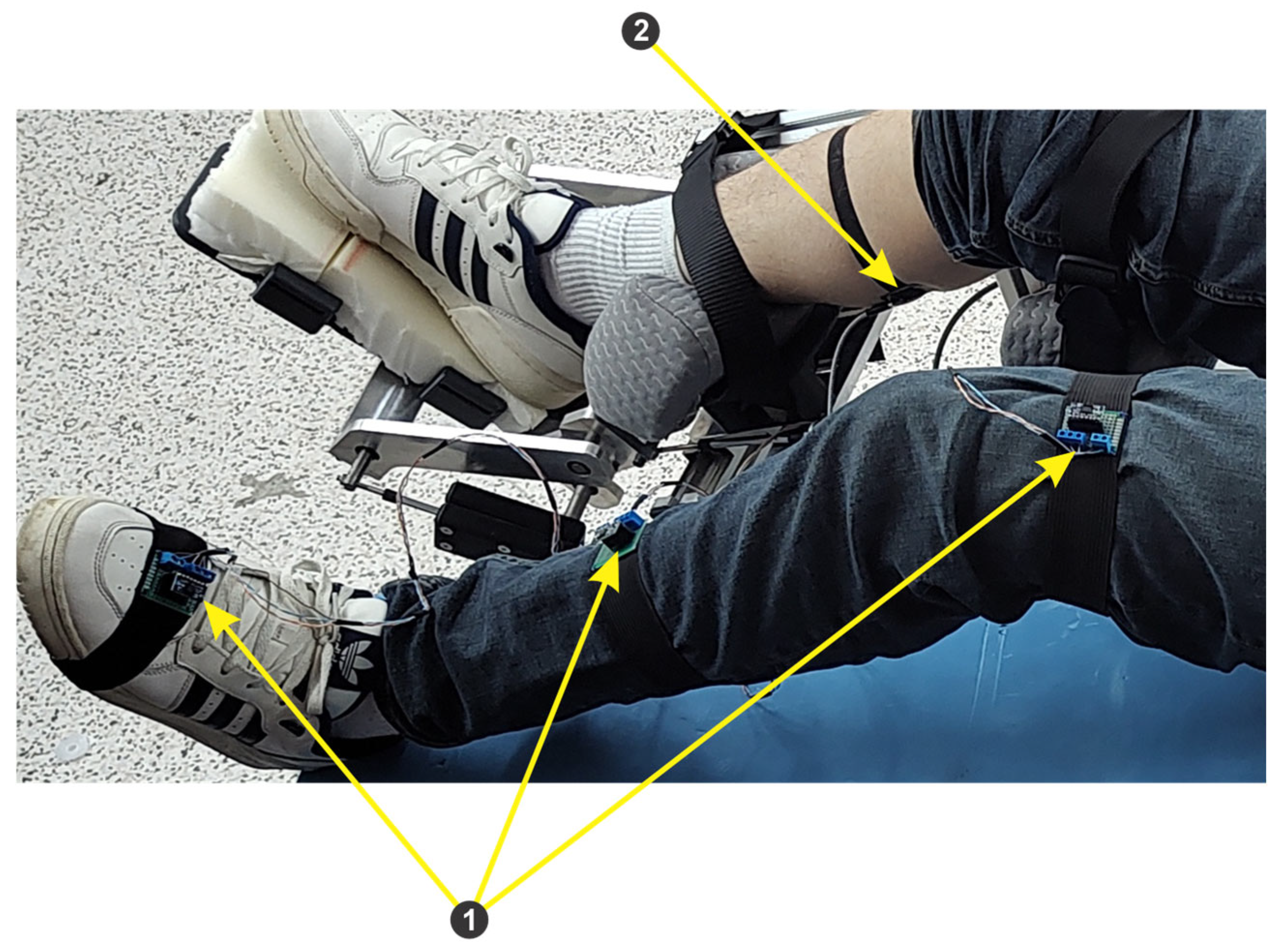
  • Module 3 consists of an EMG sensor and three IMU sensors, connected to the ESP32 microcontroller development board. The data acquired from the sensors through the ESP32 microcontroller are sent to the computer via the Wi-Fi protocol.
Figure 16. Control architecture of the parallel robot.
Technologies 13 00227 g016
Figure 17 presents the integration of the EMG sensors within the control system of the LegUp robot to monitor the patient involvement during more advanced rehabilitation stages. Muscle activity is generated by the patient during the training exercises, and the bioelectric signals (EMG) are captured by the sensors. The EMG signals are processed as presented in Figure 18 to extract the relevant characteristics, illustrating muscle activity. Consequently, in more advanced rehabilitation stages, the physician might decide to perform certain rehabilitation exercises only if the patient is actively involved in the training process. Various muscles can be targeted, Figure 17 showing an example for the thigh.
Figure 18 shows the main steps in EMG signal processing. A pre-filter using a band-pass filter with a 450 Hz frequency to remove the noise has been performed, followed by a notch filter (50 Hz), which eliminates the power line interference. After amplification, the signal is rectified, converting the negative values to positive ones. A low-pass filter was applied for smoothing to reduce fluctuations. The threshold was set initially to 0 mV, for testing purposes, but the physician will set this value according to the task, leading to the correct analysis in terms of duration, frequency, and amplitude. A visualization of the processed signal is presented in Figure 9 on the user interface.

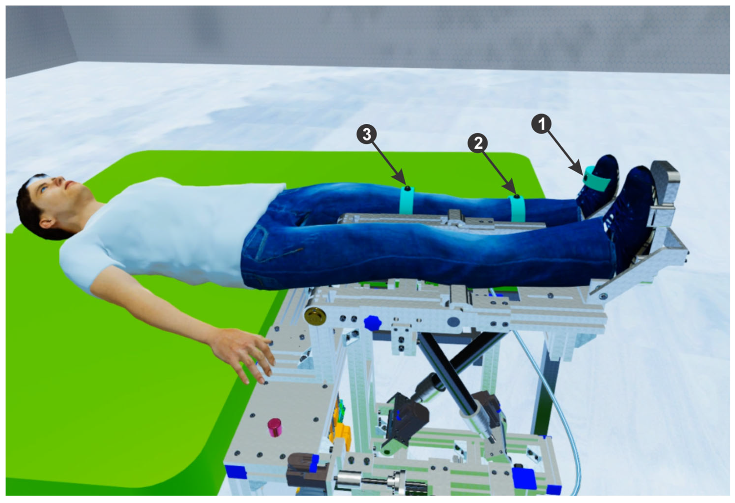
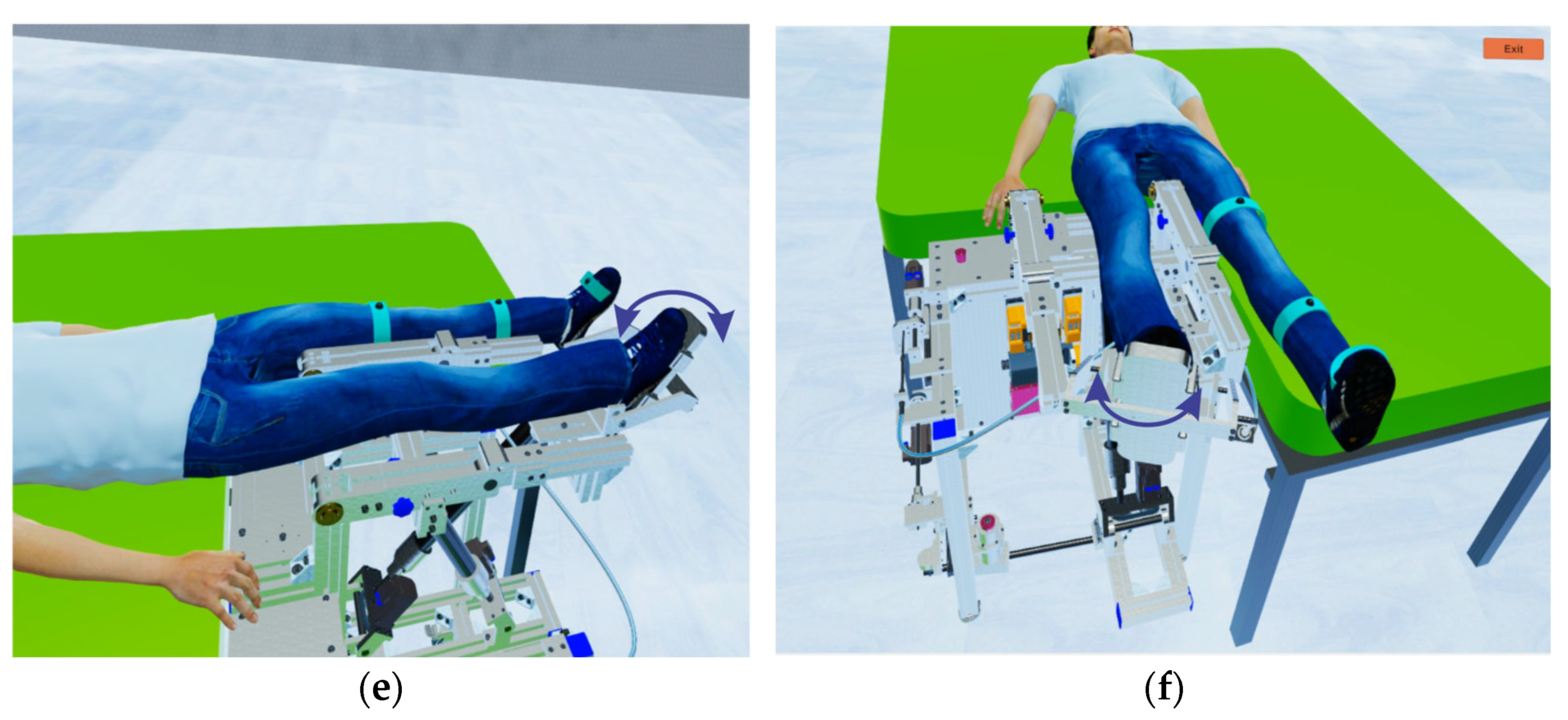
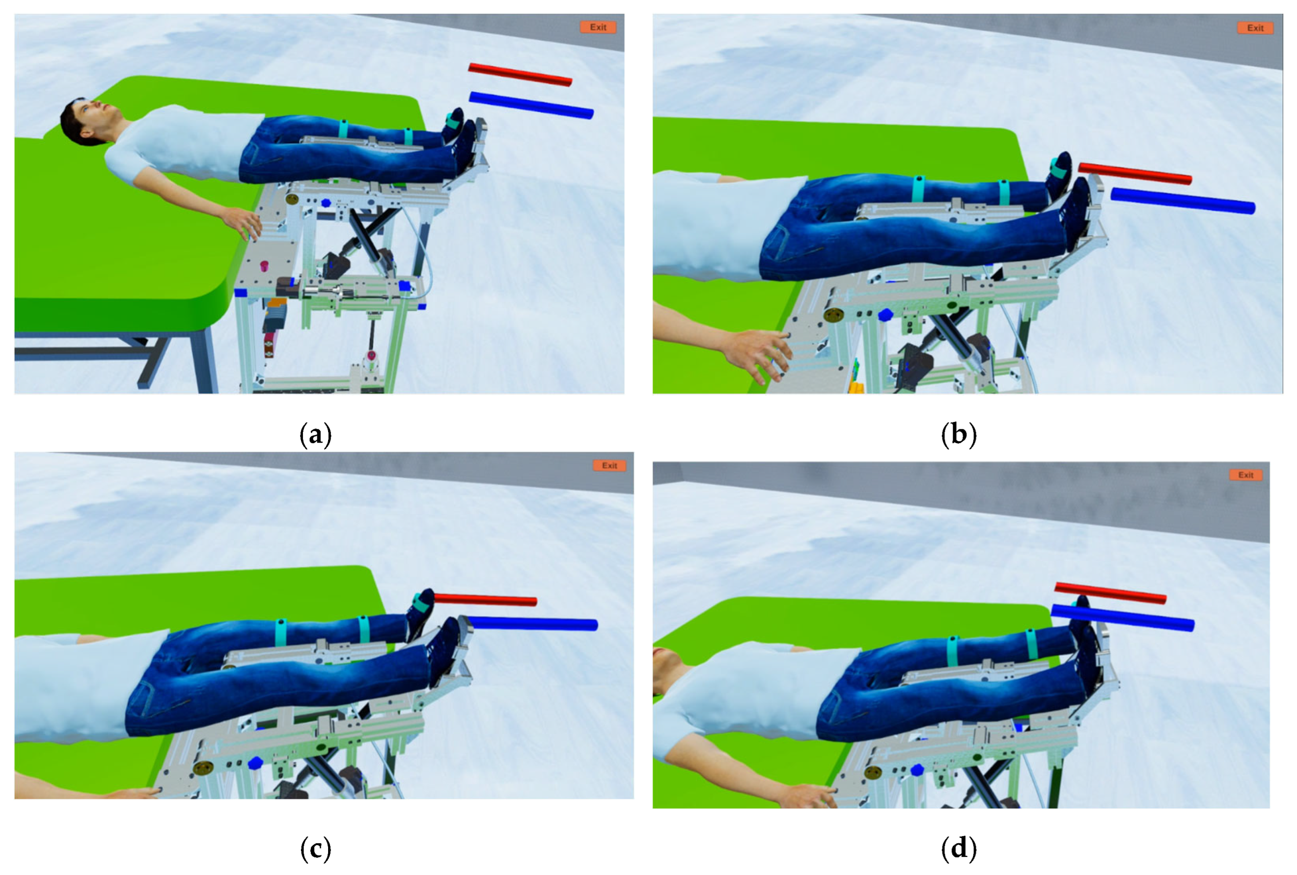
2.7. Development and Integration of the VR Application in the Mirror Therapy

The Unity 3D development environment was used to develop the VR application, since it offers a wide range of tools and functionalities that facilitate the creation of interactive and immersive experiences [34,35]. This environment is known for its flexibility, support for multiple platforms, and the vast network of community developers who provide resources and solutions. Its powerful graphics engine and the ability to integrate various technologies and plugins make Unity 3D an ideal choice for developing high-quality virtual reality applications. To create the room (Figure 19a) in the VR application, the ProBuilder (5.1.1) [36] package was used, due to its advanced modeling and design capabilities. ProBuilder allows developers to quickly and efficiently create complex geometries directly in Unity (2022.3.4f1) without the need for external 3D modeling tools. This virtual human patient (place on the digital twin of the parallel robot within the VR environment) has been developed using MakeHuman (1.2.0) [37], as in Figure 19b. This environment enables the development of realistic and customizable 3D models, offering a wide range of options for adjusting physical features such as height, weight, face shape, and body details. MakeHuman also supports automatic skeleton rigging, making it easier to animate and control avatars in virtual environments. The Siemens NX program (NX 2312) was used for the detailed design of the rehabilitation parallel robot mechanical architecture.
The virtual human avatar and the parallel robotic rehabilitation structure are exported using the .fbx extension from the MakeHuman environment, respectively, Siemens NX into the Unity 3D environment. Materials have been assigned and constraints placed in Unity 3D to enable motion control, translation, and rotation around each axis (X, Y, and Z). The virtual human avatar is placed onto the robotic rehabilitation mechanical architecture (Figure 20), and the 3 sensors (Figure 20, (1)–(3)) are attached to the healthy lower limb of the patient, which is then controlled by the therapist via the user interface. The sensors are attached as follows: one sensor is attached to the foot (Figure 20, (1)), the second to the tibia (Figure 20, (2)), and the last to the femur (Figure 20, (3)). Due to its flexibility and power in handling graphic and complex interactions, C# is used to develop the VR application. Additionally, C# offers robust support for integration with game engines and VR platforms, making it easier to develop an interactive and immersive application.

3. Results and Discussion

The use of VR technology in rehabilitation has highlighted numerous clear advantages, including a significantly higher degree of patient involvement, which contributes to increasing the efficiency of the rehabilitation process [38]. To illustrate the functionality of the developed approach for lower limb rehabilitation, a case study involving four healthy subjects, all males, with ages between 26 and 45 years old, weights between 70 and 95 kg, and heights between 175 and 190 cm, is presented. Before performing the laboratory validation tests, informed consent was signed by the subjects. Since only healthy subjects were involved in the experiments, the proposed goal was to assess the possible muscle activation, the joints range of motion and to gather user experience feedback regarding the proposed approach. With the subject lying on his back in a supine position, having the right leg anchored on the robot, a VR headset is placed on his head. Through it, the tested subject can see the VR environment, which features a digital twin of the experimental rehabilitation parallel robot and a virtual patient. To monitor the movement of the three joints (hip, knee, and ankle), the three IMU sensors (Figure 21, (1)) are attached to the subject’s right lower limb. When the subject moves the lower limb, data on the three axes (x, y, and z) of the three IMU sensors are sent to the neural network to classify the motions according to exercises performed by the rehabilitation parallel robot. To monitor the subject’s muscle tone, an EMG sensor is attached to the impaired lower limb (Figure 21, (2)), and the signal from this sensor is sent to the user interface to be displayed.
Within the rehabilitation process, the tested subject is guided by the therapist through the user interface (Figure 7, (9)) to move his healthy leg by moving the leg of the virtual human patient in VR (Figure 22a). Five types of rehabilitation exercises can be performed as follows: Hip Abduction (Figure 22b), Hip Flexion (Figure 22c), Knee Flexion (Figure 22d), Ankle Dorsiflexion (Figure 22e), and Ankle Inversion (Figure 22f). Figure 10 presents the history of rehabilitation sessions for each subject. For example, subject 1 (S1) performs an exercise called “HipAbduction”, which was repeated seven times, which has a starting amplitude (Amp.S) of −30 degrees and a final amplitude (Amp.F) of 30 degrees, having a speed of 5 rpm in a time of 25:90 s. While the patient moves his healthy lower limb, the data from the IMU sensors are sent to the neural network to classify the exercises, which are further sent to the robot (Figure 23) to perform rehabilitation exercises on the patient’s affected lower limb.
The EMG Adaptive Control protocol has been tested with the EMG sensors placed on the patients’ Gastrocnemius muscles. Figure 24 presents the VR application with the targets represented by the two colored bars that need to be reached in two different training exercises scenarios (ankle dorsiflexion and hip flexion). The patient must initiate motion, triggered by the EMG signal detected at the level of the lower joint and try to move it to reach the target. Once the motion is triggered, the LegUp robot and its digital twin perform the required motion for the lower limb to reach the target. Figure 25 presents the recorded amplitude of the EMG signal for one of the subjects, simulating a fatigue scenario. Six time windows, each with a 2 s duration, have been set, corresponding to the simulated muscle contractions. Figure 26 presents the median frequency for each of the six time windowed segments represented by the red circles, while the dashed blue line is the median frequency trend as a linear fit, indicating a clear decrease over time. The slope of approximately −2.204 Hz/sec is a clear indication of fatigue, as muscle conductivity and the burst rates are declining. Furthermore, the close fit between the computed window frequency and the linear trend suggests a consistent decline. It is highly probable that, with real patients, the decline may be more abrupt and not overlap the 2 s window, which suggests that further adjustments will be required. Nevertheless, it also proves that the proposed protocol provides the expected outcome and can be used for the approached medical task. Similarly, the RMS of the EMG signal represented in Figure 27 suggests the subjects’ fatigue, since it starts from approximately 0.38 mV after 1 s and reaches 0.17 mV at around 11 s.
The tests ended with promising results in terms of measured range of motion (using goniometers for the minimum and maximum values), system responsiveness during the mirror therapeutic exercises, and general subject involvement, which was due especially to the VR application. The user experience has been collected through feedback form rating the overall experience, comfortably, engagement, and recorded performance, all answers quantified using the 1 to 5 stars interval. The final score is 4, which suggests promising results, once the overall comfort is improved.
The current paper proposes a complex and efficient solution for lower limb rehabilitation, including a parallel robot designed for lower limb mobilization and controlled using a multi-modal interface, which consists of a classic user graphical interface enabling the set of different motion parameters and a mirror control approach. A patient avatar is used to increase the patient stimulation and create feedback. A similar approach was used in [39], where the authors developed a robotic system for the upper limb rehabilitation using an industrial end-effector robot. Nevertheless, the patient feedback is reduced (absence of sensors to collect patient signal) and the use of an industrial robot limits the reproduction of natural upper limb motions. The integration of multiple input sources in the control of the robot is another major advantage over other research in the field [18,40,41,42], foreseeing increased patient outcomes and better monitoring during the treatment period in the long run. The use of a VR avatar allows for more compelling and engaging visual feedback, which increases patient engagement and can more effectively activate the motor cortex. Using the proposed neural network enables adaptive recognition of different exercise types, reducing the need for human intervention.
The use of a parallel robotic architecture offers high accuracy, stiffness, and ability to control complex trajectories and are more suitable for precise biomechanical exercises than single-degree-of-freedom systems, enabling a wider range of motions, including lateral movements at the hip and ankle. The two anchor elements to control the knee offer safer control, especially during the acute phase when patients may have reduced muscular tonus, while its modularity and simplicity leads to lower implementation costs. Finally, the LegUp parallel robot has been designed for bedridden patients, enabling early gait rehabilitation of stroke patients in a supine position, addressing a gap in existing solutions.
The design of robot-assisted training exercises using LegUp must consider the various conditions of patients. For patients with muscle atrophy, LegUp will offer full support throughout the entire motion, utilizing higher accelerations and a larger range of motion (ROM) tailored to the patient’s specific condition. In cases of knee stiffness, careful adjustments to the ROM will be required during knee mobilization, incorporating lower accelerations to avoid discomfort while promoting increased mobility. A similar approach can be applied for patients with arthritis, where the ROM can be gradually expanded, providing gentle support to facilitate movement. For individuals with knee injuries, the focus should be on slow, controlled motions with a limited ROM during the initial stages of rehabilitation. Throughout these approaches, continuous monitoring and adjustments based on patient feedback are crucial, ensuring that individual experiences of pain, comfort, and progress inform any modifications to the robot’s setup.
The proposed architecture is modular and versatile. It can be applied to upper limb rehabilitation, provided it is equipped with appropriate mechanical robotic architecture designed for this purpose. The existing set of IMU sensors can be readily adapted for upper limb use, although the signal processing and interpretation will need to be adjusted accordingly. Additionally, a suitable user interface should be developed to enhance usability. The virtual reality environment can also be easily modified for upper limb rehabilitation, thanks to the versatility of the patient’s avatar and the system’s modular design, which simplifies the integration of different virtual models.
However, the proposed approach has certain limitations concerning especially the robotic technology. Because of the confined spaces often found in hospitals and clinics, particularly for post-stroke patients in the acute phase, the dimensions of the LegUp have been minimized. As a result, the prismatic joint movements may not accommodate the full range of motion for some patients. Additionally, gait training can be challenging to conduct due to the patient’s supine position, which restricts the overall functionality of the robot.

4. Summary and Conclusions

This research aims to increase the effectiveness and involvement of robot-assisted therapies by integrating VR and artificial intelligence. By transforming classic therapies into interactive activities, patients have a greater chance of achieving better results through greater motivation.
The novelty of the proposed approach consists of the implementation of a dual patient–robot interaction modality: mirror therapy and EMG-driven training exercises, motivating the patient using the digital twin of the robot and a patient avatar in a VR application. It specifically addresses bed-ridden patients, providing personalized support and exercises to accelerate recovery and improve the patient’s quality of life. The system uses three main components: a lower limb rehabilitation robot, a VR environment, and a sensory system featuring a neural network for signal processing. Through VR, various characteristics of the robot-assisted rehabilitation process can also be validated, allowing the testing of control algorithms in a safe environment, thus reducing the risks associated with direct physical testing.
Future work targets an upgraded control system through the simulation of various scenarios using healthy subjects, such as highly repetitive motions using various velocities and cognitive–motor integration tasks through signaling the execution of various motions of the lower limb. Longitudinal studies on efficacy evaluating the impact of mirror robotic rehabilitation combined with the developed VR in various patient populations are a long-term goal. Tailoring the robot-assisted rehabilitation according to individual patient’s needs, abilities, and progress and integrating other therapies such as functional electrical stimulation and multimodal feedback mechanisms (auditory and/or haptic) to ensure a more effective rehabilitation are also foreseen.

Author Contributions

Conceptualization, F.C. and C.V.; methodology, F.C. and B.G.; software, F.C.; validation, D.P., B.G. and C.V.; formal analysis, A.P. and A.C.; investigation, P.T.; resources, D.P.; data curation, B.G. and P.T.; writing—original draft preparation, F.C.; writing—review and editing, B.G. and D.P.; visualization, A.P. and A.C.; supervision, D.P. and B.G.; project administration, D.P.; funding acquisition, D.P. All authors have read and agreed to the published version of the manuscript.

Funding

This research was supported by the project “New frontiers in adaptive modular robotics for patient-centered medical rehabilitation—ASKLEPIOS”, funded by the European Union—NextGenerationEU, and the Romanian Government, under the National Recovery and Resilience Plan for Romania, contract no. 760071/23.05.2023, code CF 121/15.11.2022, with the Romanian Ministry of Research, Innovation, and Digitalization, within Component 9, investment I8, and by the project “Romanian Hub for Artificial Intelligence-HRIA”, Smart Growth, Digitization and Financial Instruments Program, MySMIS no. 334906.

Institutional Review Board Statement

The study was conducted in accordance with the Declaration of Helsinki involving healthy subjects. The protocol was approved by the Ethics Committee of contract no. 760071/23.05.2023 and 334906 on 12 February 2025.

Informed Consent Statement

Written informed consent has been obtained from the healthy subjects to publish this paper.

Data Availability Statement

Data are contained within the article.

Conflicts of Interest

The authors declare no conflicts of interest.

References

  1. Bindal, P.; Kumar, V.; Kapil, L.; Singh, C.; Singh, A. Therapeutic management of ischemic stroke. Naunyn-Schmiedeberg’s Arch. Pharmacol. 2024, 397, 2651–2679. [Google Scholar] [CrossRef] [PubMed]
  2. Facciorusso, S.; Spina, S.; Picelli, A.; Baricich, A.; Molteni, F.; Santamato, A. May Spasticity-Related Unpleasant Sensations Interfere with Daily Activities in People with Stroke and Traumatic Brain Injury? Secondary Analysis from the CORTOX Study. J. Clin. Med. 2024, 13, 1720. [Google Scholar] [CrossRef]
  3. Miller, E.T.; Murray, L.; Richards, L.; Zorowitz, R.; Bakas, T.; Clark, P.C.; Billinger, S.A. Comprehensive overview of nursing and interdisciplinary rehabilitation care of the stroke patient: A scientific statement from the American Heart Association. Stroke 2010, 41, 2402–2448. [Google Scholar] [CrossRef]
  4. Gandhi, D.; Sterba, A.; Khatter, H.; Pandian, J. Mirror therapy in stroke rehabilitation: Current perspectives. Ther. Clin. Risk Manag. 2020, 16, 75–85. [Google Scholar] [CrossRef]
  5. Amin, F.; Waris, A.; Iqbal, J.; Gilani, S.O.; Rehman, M.Z.U.; Mushtaq, S.; Khan, N.B.; Khan, M.I.; Jameel, M.; Tamam, N. Maximizing stroke recovery with advanced technologies: A comprehensive assessment of robot-assisted, EMG-Controlled robotics, virtual reality, and mirror therapy interventions. Results Eng. 2024, 21, 101725. [Google Scholar] [CrossRef]
  6. Geonea, I.D.; Tarnita, D.; Pisla, D.; Carbone, G.; Bolcu, A.; Tucan, P.; Georgescu, M.; Tarniță, D.N. Dynamic Analysis of a Spherical Parallel Robot Used for Brachial Monoparesis Rehabilitation. Appl. Sci. 2021, 11, 11849. [Google Scholar] [CrossRef]
  7. Hsu, S.Y.; Kuo, L.C.; Lin, Y.C.; Su, F.C.; Yang, T.H.; Lin, C.W. Effects of a Virtual Reality–Based Mirror Therapy Program on Improving Sensorimotor Function of Hands in Chronic Stroke Patients: A Randomized Controlled Trial. Neurorehabilit. Neural Repair 2022, 36, 335–345. [Google Scholar] [CrossRef] [PubMed]
  8. Gebreheat, G.; Antonopoulos, N.; Porter-Armstrong, A. Application of immersive virtual reality mirror therapy for upper limb rehabilitation after stroke: A scoping review. Neurol Sci. 2024, 45, 4173–4184. [Google Scholar] [CrossRef]
  9. Rosero-Herrera, J.D.; Acuña-Bravo, W. A lower limb rehabilitation platform with mirror therapy, electrical stimulation and virtual reality for people with limited dorsiflexion movement. HardwareX 2022, 11, e00285. [Google Scholar] [CrossRef]
  10. da Silva Jaques, E.; Figueiredo, A.I.; Schiavo, A.; Loss, B.P.; da Silveira, G.H.; Sangalli, V.A.; da Silva Melo, D.A.; Xavier, L.L.; Pinho, M.S.; Mestriner, R.G. Conventional Mirror Therapy versus Immersive Virtual Reality Mirror Therapy: The Perceived Usability after Stroke. Stroke Res. Treat. 2023, 2023, 5080699. [Google Scholar] [CrossRef]
  11. Lee, K.E.; Choi, M.; Jeoung, B. Effectiveness of Rehabilitation Exercise in Improving Physical Function of Stroke Patients: A Systematic Review. Int. J. Environ. Res. Public Health 2022, 19, 12739. [Google Scholar] [CrossRef] [PubMed]
  12. Banyai, A.D.; Brișan, C. Robotics in Physical Rehabilitation: Systematic Review. Healthcare 2024, 12, 1720. [Google Scholar] [CrossRef] [PubMed]
  13. Tohanean, N.; Tucan, P.; Vanta, O.-M.; Abrudan, C.; Pintea, S.; Gherman, B.; Burz, A.; Banica, A.; Vaida, C.; Neguran, D.A.; et al. The Efficacity of the NeuroAssist Robotic System for Motor Rehabilitation of the Upper Limb—Promising Results from a Pilot Study. J. Clin. Med. 2023, 12, 425. [Google Scholar] [CrossRef]
  14. Luo, Z.; Zhou, Y.; He, H.; Lin, S.; Zhu, R.; Liu, Z.; Liu, J.; Liu, X.; Chen, S.; Zou, J.; et al. Synergistic Effect of Combined Mirror Therapy on Upper Extremity in Patients with Stroke: A Systematic Review and Meta-Analysis. Front. Neurol. 2020, 11, 155. [Google Scholar] [CrossRef]
  15. Ramachandran, V.S.; Rogers-Ramachandran, D. Synaesthesia in phantom limbs induced with mirrors. Proc. Biol. Sci. 1996, 263, 377–386. [Google Scholar] [PubMed]
  16. Deconinck, F.J.; Smorenburg, A.R.; Benham, A.; Ledebt, A.; Feltham, M.G.; Savelsbergh, G.J. Reflections on mirror therapy: A systematic review of the effect of mirror visual feedback on the brain. Neurorehabil. Neural Repair 2015, 29, 349–361. [Google Scholar] [CrossRef]
  17. Miclaus, R.S.; Roman, N.; Henter, R.; Caloian, S. Lower Extremity Rehabilitation in Patients with Post-Stroke Sequelae through Virtual Reality Associated with Mirror Therapy. Int. J. Environ. Res. Public Health 2021, 18, 2654. [Google Scholar] [CrossRef] [PubMed]
  18. Yang, Z.; Guo, S.; Hirata, H.; Kawanishi, M. A Mirror Bilateral Neuro-Rehabilitation Robot System with the sEMG-Based Real-Time Patient Active Participant Assessment. Life 2021, 11, 1290. [Google Scholar] [CrossRef]
  19. Nizamis, K.; Athanasiou, A.; Almpani, S.; Dimitrousis, C.; Astaras, A. Converging Robotic Technologies in Targeted Neural Rehabilitation: A Review of Emerging Solutions and Challenges. Sensors 2021, 21, 2084. [Google Scholar] [CrossRef]
  20. Zhang, H.; Liao, Y.; Zhu, C.; Meng, W.; Liu, Q.; Xie, S.Q. VR-Aided Ankle Rehabilitation Decision-Making Based on Convolutional Gated Recurrent Neural Network. Sensors 2024, 24, 6998. [Google Scholar] [CrossRef]
  21. Fan, H.; Luo, Z. Functional integration of mirror neuron system and sensorimotor cortex under virtual self-actions visual perception. Behav. Brain Res. 2022, 423, 113784. [Google Scholar] [CrossRef] [PubMed]
  22. Hercog, D.; Lerher, T.; Truntič, M.; Težak, O. Design and Implementation of ESP32-Based IoT Devices. Sensors 2023, 23, 6739. [Google Scholar] [CrossRef]
  23. Thavitchasri, P.; Maneetham, D.; Crisnapati, P.N. Intelligent Surface Recognition for Autonomous Tractors Using Ensemble Learning with BNO055 IMU Sensor Data. Agriculture 2024, 14, 1557. [Google Scholar] [CrossRef]
  24. Wang, J.H.; Kim, J.Y. Development of a whole-body walking rehabilitation robot and power assistive method using EMG signals. Intell. Serv. Robot. 2023, 16, 139–153. [Google Scholar] [CrossRef]
  25. Iordan, A.E. A comparative study of three heuristic functions used to solve the 8-puzzle. Br. J. Math. Comput. Sci. 2016, 16, 1–18. [Google Scholar] [CrossRef] [PubMed]
  26. Iordan, A.E. Optimal solution of the Guarini puzzle extension using tripartite graphs. IOP Conf. Ser.-Mater. Sci. Eng. 2019, 477, 012046. [Google Scholar] [CrossRef]
  27. Kridera, S.; Kanavos, A. Exploring Trust Dynamics in Online Social Networks: A Social Network Analysis Perspective. Math. Comput. Appl. 2024, 29, 37. [Google Scholar] [CrossRef]
  28. Major, Z.Z.; Vaida, C.; Major, K.A.; Tucan, P.; Brusturean, E.; Gherman, B.; Birlescu, I.; Craciunaș, R.; Ulinici, I.; Simori, G.; et al. Comparative Assessment of Robotic versus Classical Physical Therapy Using Muscle Strength and Ranges of Motion Testing in Neurological Diseases. J. Pers. Med. 2021, 11, 953. [Google Scholar] [CrossRef] [PubMed]
  29. Covaciu, F.; Pisla, A.; Iordan, A.E. Development of a virtual reality simulator for an intelligent robotic system used in ankle rehabilitation. Sensors 2021, 21, 1537. [Google Scholar] [CrossRef]
  30. Kumar, J.; Patel, T.; Sugandh, F.; Dev, J.; Kumar, U.; Adeeb, M.; Kachhadia, M.P.; Puri, P.; Prachi, F.; Zaman, M.U.; et al. Innovative Approaches and Therapies to Enhance Neuroplasticity and Promote Recovery in Patients with Neurological Disorders: A Narrative Review. Cureus 2023, 15, e41914. [Google Scholar] [CrossRef]
  31. Wareham, L.K.; Liddelow, S.A.; Temple, S.; Benowitz, L.I.; Di Polo, A.; Wellington, C.; Goldberg, J.L.; He, Z.; Duan, X.; Bu, G.; et al. Solving Neurodegeneration: Common Mechanisms and Strategies for New Treatments; BioMed Central Ltd.: London, UK, 2022. [Google Scholar]
  32. Yang, Y.L.; Guo, J.L.; Yao, Y.F.; Yin, H.S. Development of a Compliant Lower-Limb Rehabilitation Robot Using Underactuated Mechanism. Electronics 2023, 12, 3436. [Google Scholar] [CrossRef]
  33. Vaida, C.; Birlescu, I.; Pisla, A.; Carbone, G.; Plitea, N.; Ulinici, I.; Gherman, B.; Puskas, F.; Tucan, P.; Pisla, D. RAISE-An Innovative Parallel Robotic System for Lower Limb Rehabilitation. Adv. Theory Pract. 2019, 4, 293–302. [Google Scholar]
  34. Covaciu, F.; Iordan, A.-E. Control of a Drone in Virtual Reality Using MEMS Sensor Technology and Machine Learning. Micromachines 2022, 13, 521. [Google Scholar] [CrossRef]
  35. Fang, Y.-M. Exploring Usability, Emotional Responses, Flow Experience, and Technology Acceptance in VR: A Comparative Analysis of Freeform Creativity and Goal-Directed Training. Appl. Sci. 2024, 14, 6737. [Google Scholar] [CrossRef]
  36. Huang, Y.; Guo, Z.; Chu, H.; Sengupta, R. Evacuation Simulation Implemented by ABM-BIM of Unity in Students’ Dormitory Based on Delay Time. ISPRS Int. J. Geo-Inf. 2023, 12, 160. [Google Scholar] [CrossRef]
  37. Meier, C.; Berriel, I.S.; Nava, F.P. Creation of a Virtual Museum for the Dissemination of 3D Models of Historical Clothing. Sustainability 2021, 13, 12581. [Google Scholar] [CrossRef]
  38. Catania, V.; Rundo, F.; Panerai, S.; Ferri, R. Virtual Reality for the Rehabilitation of Acquired Cognitive Disorders: A Narrative Review. Bioengineering 2024, 11, 35. [Google Scholar] [CrossRef]
  39. Wei, D.; Hua, X.Y.; Zheng, M.X.; Wu, J.J.; Xu, J.G. Effectiveness of robot-assisted virtual reality mirror therapy for upper limb motor dysfunction after stroke: Study protocol for a single-center randomized controlled clinical trial. BMC Neurol. 2022, 22, 307. [Google Scholar] [CrossRef]
  40. Nisar, H.; Annamraju, S.; Deka, S.A.; Horowitz, A.; Stipanović, D.M. Robotic mirror therapy for stroke rehabilitation through virtual activities of daily living. Comput. Struct. Biotechnol. J. 2024, 24, 126–135. [Google Scholar] [CrossRef]
  41. Rong, J.; Ding, L.; Xiong, L.; Zhang, W.; Wang, W.; Deng, M.; Wang, Y.; Chen, Z.; Jia, J. Mirror Visual Feedback Prior to Robot-Assisted Training Facilitates Rehabilitation After Stroke: A Randomized Controlled Study. Front. Neurol. 2021, 12, 683703. [Google Scholar] [CrossRef]
  42. Chen, Y.W.; Li, K.Y.; Lin, C.H.; Hung, P.H.; Lai, H.T.; Wu, C.Y. The effect of sequential combination of mirror therapy and robot-assisted therapy on motor function, daily function, and self-efficacy after stroke. Sci. Rep. 2023, 13, 16841. [Google Scholar] [CrossRef] [PubMed]
Figure 1. General architecture of the lower limb parallel robot.
Technologies 13 00227 g001
Figure 2. The robot-assisted rehabilitation robot medical protocol using LegUp.
Technologies 13 00227 g002
Figure 3. The EMG signal processing: (a) Algorithm used to determine and track the median frequency of the EMG signal. (b) Tracked parameter of the EMG signal to detect the patient’s fatigue is the RMS amplitude.
Technologies 13 00227 g003
Figure 4. Interconnection of the components.
Technologies 13 00227 g004
Figure 6. Software architecture.
Technologies 13 00227 g006
Figure 10. User interface: Sessions history.
Technologies 13 00227 g010
Figure 13. Accuracy and loss.
Technologies 13 00227 g013
Figure 14. Kinematic scheme of the parallel robot. (1) Hip and knee module. (2) Ankle module.
Technologies 13 00227 g014
Figure 15. The experimental model of the parallel robot together with the user and the patient. (1) Parallel robot; (2) Control module; (3) Monitors for displaying the UI and VR application; (4) Patient; (5) VR headset; (6) EMG sensor placement; (7) IMU sensors placement; (8) User.
Technologies 13 00227 g015
Figure 17. The control system of LegUp integrating the EMG sensors.
Technologies 13 00227 g017
Figure 18. The EMG signal processing flowchart.
Technologies 13 00227 g018
Figure 19. (a) Development of the room. (b) Development of the virtual human patient.
Technologies 13 00227 g019
Figure 20. Parallel robot together with human virtual patient in a VR environment.
Technologies 13 00227 g020
Figure 21. Attaching sensors to the healthy subject’s lower limbs.
Technologies 13 00227 g021
Figure 22. Rehabilitation exercises in the VR environment using a robotic rehabilitation system. (a) Start position; (b) Hip Abduction; (c) Hip Flexion; (d) Knee Flexion; (e) Ankle Dorsiflexion; (f) Ankle Inversion.
Technologies 13 00227 g022aTechnologies 13 00227 g022b
Figure 23. Performing rehabilitation exercises by the healthy subject.
Technologies 13 00227 g023
Figure 24. Rehabilitation exercises using adaptive EMG control. (a) Start position. (b) Positioning the bars for exercises. (c) Ankle dorsiflexion exercise. (d) Hip Flexion Exercise.
Technologies 13 00227 g024
Figure 25. EMG signal amplitude for the gastrocnemius muscle of a healthy subject simulating fatigue.
Technologies 13 00227 g025
Figure 26. EMG signal median frequency for every windowed segment.
Technologies 13 00227 g026
Figure 27. EMG signal RMS values over the time windows.
Technologies 13 00227 g027
Disclaimer/Publisher’s Note: The statements, opinions and data contained in all publications are solely those of the individual author(s) and contributor(s) and not of MDPI and/or the editor(s). MDPI and/or the editor(s) disclaim responsibility for any injury to people or property resulting from any ideas, methods, instructions or products referred to in the content.

