Abstract
Hydrogen compression is a critical process in hydrogen storage and distribution, particularly for energy infrastructure and transportation. As hydrogen technologies expand beyond limited industrial applications, they are increasingly supporting the green economy, including offshore energy systems, smart ports, and sustainable marine industries. Efficient compression technologies are essential for ensuring reliable hydrogen storage and distribution across these sectors. This study focuses on optimizing hydrogen compression using a Liquid Piston Hydrogen Compressor through numerical simulations and scaling analysis. The research examines the influence of compression chamber geometry, including variations in radius and height, on thermal behavior and energy efficiency. A computational model was developed using COMSOL Multiphysics® 6.0, incorporating Computational Fluid Dynamics (CFD) and heat transfer modules to analyze thermodynamic processes. The results highlight temperature distribution in hydrogen, working fluid, and chamber walls at different initial pressures (3.0 MPa and 20.0 MPa) and compression stroke durations. Larger chamber volumes lead to higher temperature increases but reach thermal stabilization. Increasing the chamber volume allows for a significant increase in the performance of the hydraulic compression system with a moderate increase in the temperature of hydrogen. These findings provide insights into optimizing hydrogen compression for enhanced production and broader applications.
1. Introduction
In recent years, European countries have increasingly focused on enhancing the share of hydrogen energy in their energy mix. This transition is driven by a desire to decelerate growth and reduce the consumption of fossil fuels [1,2]. Hydrogen addresses three critical energy challenges: reducing greenhouse gas emissions, enhancing energy security, and lowering air pollution levels [3]. While industry sectors like chemical production and refueling stations remain primary areas for hydrogen utilization, emerging applications in marine transport, offshore wind-to-hydrogen systems, and port infrastructure are further expanding hydrogen’s role in clean energy transitions. These developments support the sea-based blue economy, promoting sustainable use of marine resources while contributing to economic growth and environmental protection [3,4,5,6,7,8]. In 2023, global hydrogen production reached 97 million tons, with less than 1% classified as low-emission. However, projections suggest that low-emission hydrogen production could increase to 49 million tons per annum by 2030. This increase necessitates compression systems capable of managing substantially larger volumes and increased throughput [9].
The high energy density of hydrogen and the technical feasibility of its production through water electrolysis allow for the creation and storage of energy reserves [10]. As a result, the development of efficient, economically viable, and safe hydrogen production and utilization technologies has become a key focus for the future hydrogen economy [11,12,13]. Despite its advantages, hydrogen presents several challenges. It requires additional energy for production and has the lowest volumetric energy density compared to other commonly used fuels [14]. These limitations underscore the need for efficient solutions for its production, storage, and transportation [15,16,17,18,19,20].
Compressed hydrogen is one of the most promising energy carriers, essential for advancing energy storage capabilities and establishing a robust foundation for a sustainable energy sector. The process of hydrogen compression not only facilitates its integration into the existing energy infrastructure but also significantly enhances the efficiency of storage and distribution systems [21]. By increasing the volumetric energy density of hydrogen through compression, it becomes more practical for a diverse array of applications—from industrial processes to power hydrogen fuel cell vehicles. This increase in density is crucial for the economic and operational feasibility of hydrogen use across various sectors [22,23,24,25,26].
Recent studies have highlighted the importance of optimizing compression technologies for hydrogen storage and energy systems, emphasizing thermal management and system scalability [27,28,29,30,31,32,33].
Hydrogen compression involves various types of compressors, each tailored to specific operational demands. Mechanical compressors like reciprocating pistons and diaphragms are traditionally used for their high-pressure capabilities despite their inefficiencies and high maintenance costs [34,35,36]. Centrifugal compressors, however, offer more efficient and contamination-free operations due to their oil-free designs, although they come with higher initial costs and complex design considerations [37,38]. Furthermore, innovative technologies such as Metal Hydride Hydrogen Compressors and Electrochemical Hydrogen Compressors are emerging [39,40,41,42,43,44]. Each type of compressor presents unique benefits and challenges. Extensively detailed in the literature [45,46,47,48], these hydrogen compression technologies are analyzed for their operational principles, strengths, and limitations, providing a comprehensive understanding of their roles in the broader context of hydrogen infrastructure development.
Despite the extensive exploration of various hydrogen compression technologies, this paper focuses on the Liquid Piston Hydrogen Compressor. LPHCs represent a significant advancement in hydrogen technology by leveraging the unique properties of a liquid piston, which offers a more efficient and less abrasive alternative to traditional mechanical compressors [49,50].
Liquid piston technology facilitates near-isothermal compression, meaning that the temperature within the compression chamber remains relatively stable throughout the process [3]. This stability is achieved as the heat generated during hydrogen compression is absorbed by the liquid medium, optimizing energy use and reducing thermal stress on the system. This method not only enhances the efficiency of the compression process but also extends the operational lifespan of the compressor [21].
Additionally, the scalable nature of LPHCs allows for flexible operation across a wide range of applications, from large-scale industrial hydrogen storage solutions to smaller, more localized hydrogen refueling stations for vehicles. This adaptability, coupled with reduced mechanical wear and the potential for lower maintenance costs, positions liquid piston compressors as a key technology in the development of sustainable hydrogen infrastructure.
The liquid piston is not a new concept, with its earliest known application dating back to 1906 in an internal combustion engine used for pumping water, known as the Humphrey pump. This pump operated on the Atkinson cycle and demonstrated efficiencies of 5% to 10% [51,52]. Based on this foundational technology, the modern concept of liquid piston gas compression employs a column of liquid to compress gas directly in a fixed-volume chamber. Once the compression stroke is complete, the heated fluid is channeled from the compression chamber into the heat exchanger, where it is cooled. This approach offers advantages over reciprocating compressors in terms of cooling, as there is no need for external heat exchangers on the compression chambers [53].
The use of a liquid piston eliminates gas leakage from the compression chamber and removes the friction associated with mechanical sliding seals found in conventional compressors, thereby improving the efficiency of gas compression. Using a simplified model, it has been demonstrated that this approach can increase compression efficiency from 70% to over 84–86% [54]. Liquid piston compressors are particularly advantageous for hydrogen compression due to their ability to handle high pressures and reduce the impact and vibration of the piston, making them suitable for applications such as hydrogen refueling stations and hydrogen storage [55,56,57]. Further investigation of thermodynamic processes in the hydrogen hydraulic compression system through numerical simulation and analysis of results can allow estimation of energy consumption and determination of conditions, which would lead to increased efficiency of operation of the considered hydrogen hydraulic compression system [58].
In the context of developing sustainable energy technologies, particular attention is given to effective methods of hydrogen compression [59,60,61,62]. This article examines the scaling of the working chamber in a liquid piston hydrogen compression system, enabling the optimization of compression processes across a range of industrial applications.
Previous studies on hydrogen compression systems have mainly focused on mechanical compressors or idealized liquid piston concepts without systematic investigation of chamber geometry scaling. This work addresses the research gap by analyzing the influence of chamber dimensions and compression duration under constant compression ratio conditions using CFD simulations. The study contributes insights into the coupling between chamber size, heat transfer behavior, and energy efficiency in liquid piston hydrogen compressors, aiming to support the development of optimized compression systems for high-pressure hydrogen storage applications.
Specifically, this study systematically investigates the influence of compression chamber scaling under constant compression ratio conditions, analyzing how chamber size and compression stroke duration affect thermal behavior and energy efficiency.
The study focuses on modifying geometric parameters—specifically, the radius and height of the chamber—to analyze their impact on hydrogen compression performance. This approach not only improves the technical characteristics of the system but also provides essential data for developing more efficient and cost-effective solutions in the fields of hydrogen storage and transportation.
We would like to note that the initial concept of this research was first presented at the 2023 European Conference on Renewable Energy Systems (ECRES 2023), held in Riga, Latvia, from 18 to 20 May 2023: “Study of Thermodynamic Processes of Hydraulic Compression of Hydrogen by Numerical Simulation”. That earlier work included a preliminary analysis focused solely on chamber height. In contrast, the present manuscript provides a comprehensive analysis that simultaneously considers chamber radius, height, and volume, supported by refined modeling and extended simulation results.
In Section 2, the design and operation of the compressor are described, which uses liquid pistons to achieve higher compression ratios with reduced energy loss and mechanical wear. Section 3 presents a description of the numerical model and shows the distribution of temperature in hydrogen, the liquid, and the chamber walls over the duration of a single compression stroke. In Section 4, the impact of scaling the volume of the hydrogen compression chamber on thermodynamic processes and ways to enhance productivity are examined. Section 5 summarizes the research results, which are of interest for the design of the hydraulic compression system.
2. Hydrogen Compression Using a Liquid Piston System
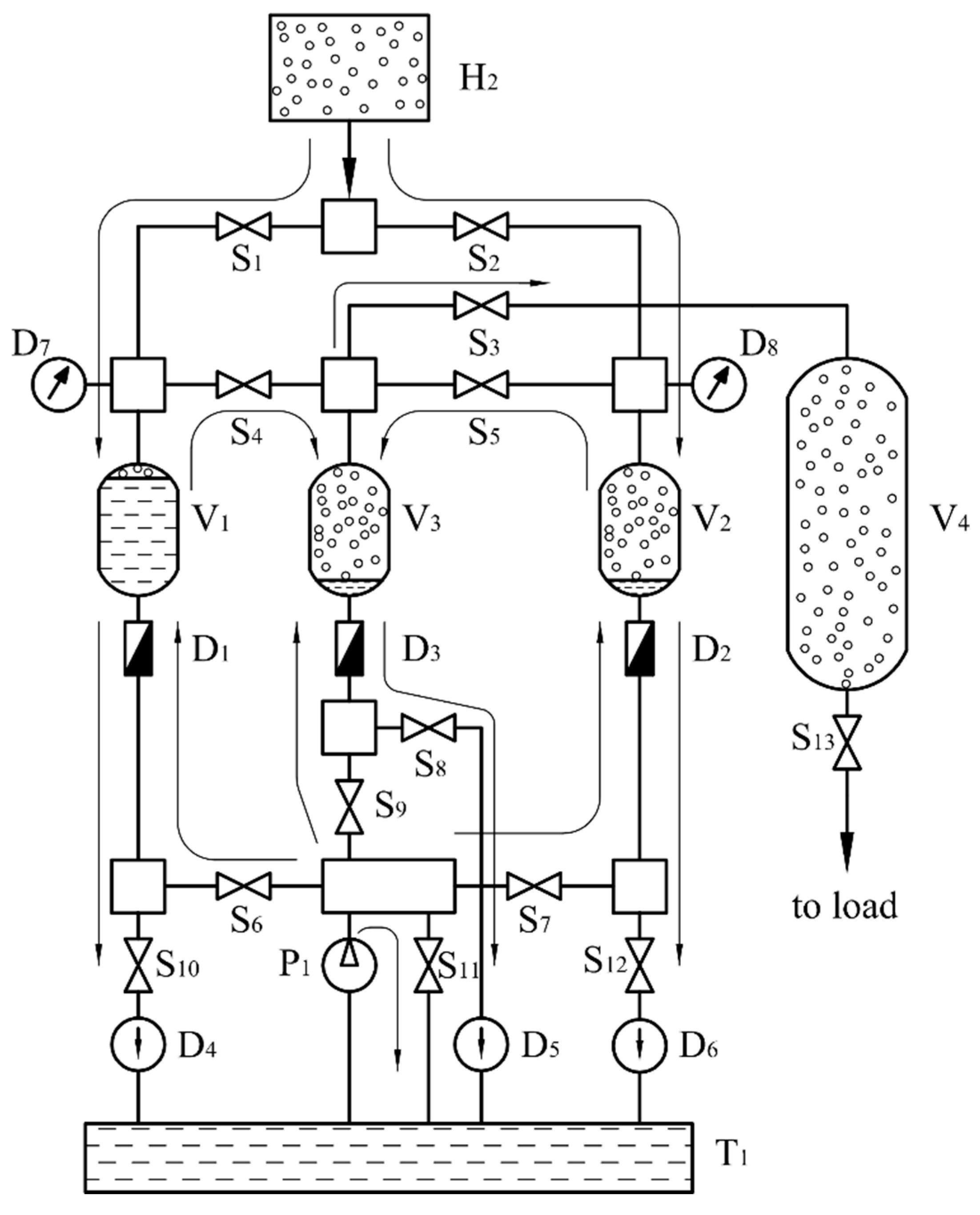
The developed system advances the liquid piston concept for hydrogen compression [63]. Figure 1 illustrates the compressor, which uses liquid pistons to achieve higher compression ratios with reduced energy loss and mechanical wear. The system design is focused on applications that require high reliability, such as refueling stations and large-scale hydrogen storage.
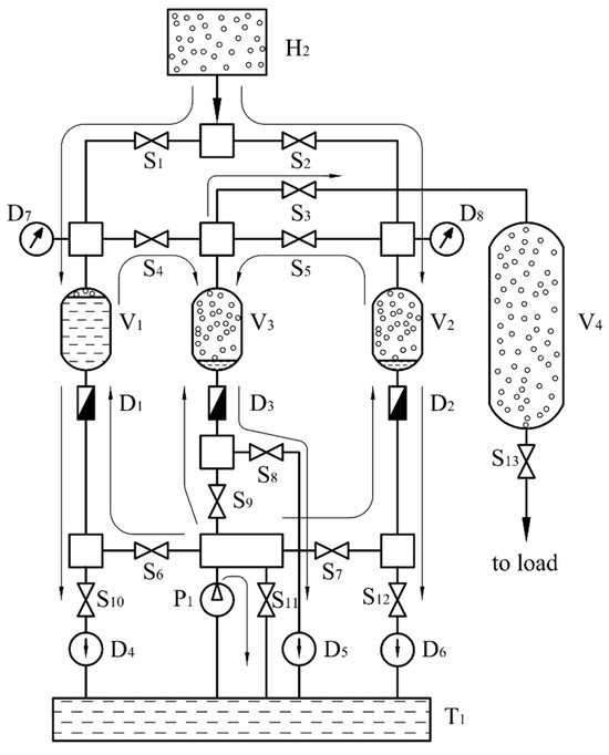
Figure 1.
Schematic diagram of the connection between the working cylinders and the hydrogen tanks in the hydraulic compressor: H2—low-pressure hydrogen tank; V1–V3—compression cylinders; V4—high-pressure buffer cylinder; T1—working fluid tank; P1—hydraulic pump; S1–S13—servo valves; D1–D3—flow meters; D4–D6—optical sensors.
As shown in Figure 1, the system includes a low-pressure hydrogen storage tank, H2, that feeds into two primary stage cylinders, V1 and V2, and one secondary stage cylinder, V3, followed by a high-pressure storage cylinder, V4. These components are connected by pipelines and controlled by a hydraulic system that includes a tank T1 with working fluid powered by a high-pressure pump P1.
Operation is managed by servo-controlled valves S1 to S13 that direct the flow of hydrogen and hydraulic fluid. Flow meters D1, D2, and D3 monitor and control compression ratio, while optical sensors D4, D5, and D6 ensure precision and system integrity. The hydrogen fills the cylinders at the start of each cycle, followed by the working fluid to compress the gas. After compression, hydrogen moves to the next stage or into high-pressure storage, optimizing efficiency and reducing energy waste.
The operational sequence continues with hydrogen pressure in cylinder V3 equalizing with cylinders V1 and V2. When this occurs, valves S3 and S9 open to allow the working fluid into V3 and transfer compressed hydrogen to buffer cylinder V4, controlled by the flow meter D3. As hydrogen exits V3, valve S8 opens to refill it from V1 and V2, with optical sensor D5 indicating when to close S8. This cycle allows efficient hydrogen to accumulate in buffer cylinder V4, subsequently directed to a refueling station dispenser via valve S13. Valve S11 allows the pump P1 to operate while other valves are closed, ensuring continuous fluid flow.
The system compresses hydrogen to pressures between 50.0 MPa and 100.0 MPa, making it suitable for refueling stations for hydrogen-fueled vehicles, as well as for transportation, various industrial applications, maritime sectors, port operations, and offshore energy systems. The primary focus of this system is the hydrogen compression working chamber, which is crucial for both performance and safety [64,65]. A detailed analysis of this chamber will be provided in the following section.
The proposed system employs digital sensors to monitor and control the flow rate of the working fluid within the compression chambers. This feature facilitates the dynamic adjustment of hydrogen compression levels to adapt to varying operational conditions, such as those associated with intermittent renewable energy sources.
Adjusting the compression system dynamically optimizes time and energy consumption by modifying the compression stroke length and the compression ratio. This adjustment also aids in managing heat dissipation, which in turn leads to a reduction of the cooling costs associated with the system.
Various configurations of the compression chambers are explored, including options with one, two, and three chambers. A configuration with three chambers, divided into two stages, is capable of handling a wide range of hydrogen pressures, maintaining up to 70.0 MPa at the outlet with inlet pressures that vary from 0.1 to 3.0 MPa. The size and volume of the compression chambers are tailored based on the required output and power needs.
3. Numerical Simulation of Hydrogen Compression in a Chamber
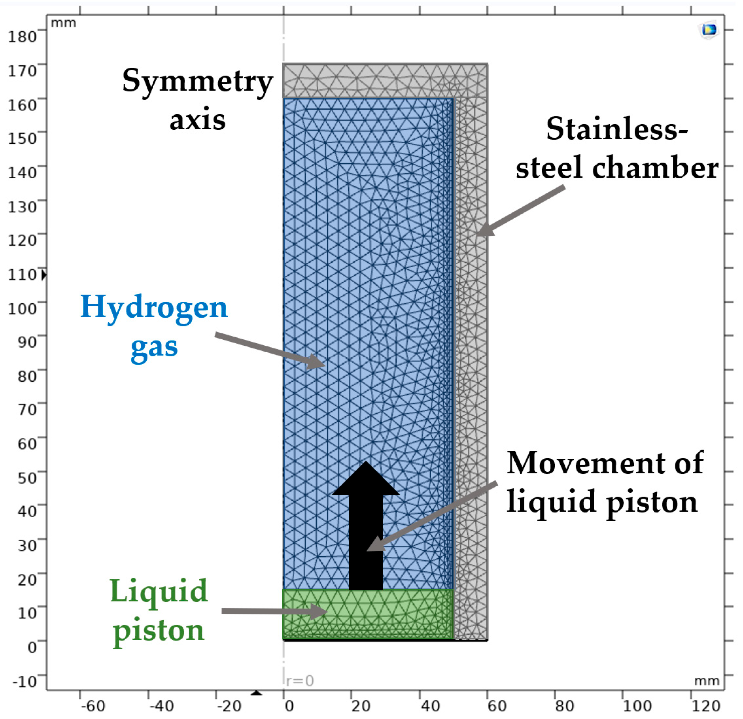
The hydrogen compression process in the chamber has been numerically simulated using COMSOL Multiphysics® software, which incorporates CFD and Heat Transfer modules. The reference computational model is a semi-symmetric stainless-steel chamber, detailed as follows (Figure 2):

Figure 2.
Reference computational model of the stainless-steel compression chamber, where hydrogen is compressed by the working fluid entering from below. The figure shows the mesh distribution used in the simulation, including refined grid cells in the central region and along the gas–liquid interface boundaries.
- Dimensions: height h = 145 mm, inner radius r = 50 mm, wall thickness w = 5 mm.
- Volume v = 1.14 L.
The initial conditions define hydrogen at pressures of P1 = 3.0 MPa or 20.0 MPa and a temperature of 300 K at the beginning of compression. The liquid piston and chamber walls are also included in the thermal analysis.
The construction of the calculation model is carried out within the framework of the assumptions that the thermal conductivity of the working fluid is significantly lower than the thermal conductivity of hydrogen and that during the process of filling the compression chamber with the working fluid, there is no turbulence and mixing between the media. In the numerical model, the liquid piston was considered a quasi-incompressible and mechanically stable medium.
A 2D axisymmetric approach was adopted to reduce computational costs and simplify meshing without compromising accuracy [66].
The simulation captures the thermodynamic behavior of hydrogen, considering heat exchange among the gas, the working fluid, the chamber walls and the external environment. The numerical simulation solves the conservation equations of mass, momentum (Navier–Stokes), and energy. Hydrogen gas is modeled as an ideal gas. The liquid piston is treated as a moving boundary without internal mixing or turbulence. Heat transfer is modeled through conduction within the gas, liquid, and chamber walls and convection at external surfaces. These assumptions simplify the model while preserving accuracy in capturing the key thermodynamic behavior. The transient heat transfer equation used in the model is:
where:
—thermal conductivity.
—the specific heat capacity.
—the velocity vector.
—the temperature.
—the rate of change of temperature over time.
Accurate simulation results depend on the physical properties of hydrogen, the working fluid, and the stainless-steel chamber. These properties—such as molar mass, heat capacity, thermal conductivity, and density—are detailed in Appendix A.
The height of the liquid column is determined based on the chamber volume and a compression coefficient = 5.0. Figure 2 illustrates the location of the liquid piston within the chamber, showing the grid cell distribution in the central region and at the boundaries of the gas-liquid interface.
In the chamber, the fluid and gas compress together. The liquid’s higher density and specific heat capacity enhance heat absorption. In the numerical model, the initial height of the liquid column is set as a constant value of 100 mm in the base model to establish the initial conditions and simplify the setup (Figure 3). However, during the compression process, the liquid column height incrementally increases as the liquid piston rises and compresses the gas. This dynamic change in the liquid column height is accounted for in the simulation through discrete volume changes over time. Figure 3 illustrates the temperature distribution within the compression chamber at different time points during a single compression stroke.
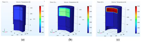
Figure 3.
Temperature distribution of hydrogen in the working chamber during a single compression stroke: (a) t = 5 s, (b) t = 15 s, (c) t = 20 s. A common temperature scale ranging from 300 K to 550 K is applied to all subfigures to illustrate the dynamic temperature changes during the compression stroke.
The form geometry module is used for the gas domain. The mass of the gas is conserved in this domain, and heating due to the compression of the gas is introduced as a volumetric heat source, which goes into the temperature equation. In this model, we use prescribed liquid piston motion with constant velocity. To save time in the calculation, we do not change mesh after every time step, but instead, we use deforming mesh, which means that the same number of cells is conserved, but the aspect ratio of the cells changes during the compression process. Although a formal mesh independence test was not conducted due to computational constraints, the mesh density and refinement were chosen according to best practices for CFD simulations, ensuring accurate resolution of heat transfer processes, similar to the approach discussed in [67].
The numerical model incorporates several simplifying assumptions to maintain computational feasibility. Hydrogen is modeled as an ideal gas; turbulence and mixing effects at the gas-liquid interface are neglected, and a fixed deforming mesh is employed without dynamic remeshing. While these assumptions enable efficient computation, they may introduce minor deviations in the simulation results, especially under high compression ratios and rapid transient conditions.
The model does not consider the increase in chamber wall temperature due to heat accumulation, as the compression process at the end of each stroke assumes cooling of the liquid and the external surface of the chamber back to initial values.
At the beginning of the compression process, the hydrogen temperature is 300 K. Figure 3a ( = 5 s) shows the early stage of compression, where the temperature distribution remains relatively uniform, but slight heating is noticeable in the upper region of the chamber. The working fluid is already moving, and compression is in progress. As compression continues (Figure 3b, = 15 s), localized heating becomes more pronounced in the upper part of the chamber, where hydrogen is most compressed. The temperature reaches approximately 400 K, forming a noticeable thermal gradient. At the final stage of compression (Figure 3c, = 20 s), the highest temperatures, exceeding 500 K, appear near the top of the chamber. This confirms the formation of a strong thermal gradient, with the hottest region in the compressed hydrogen zone. These results highlight the dynamic thermal behavior of hydrogen during compression, emphasizing the need for effective thermal management to prevent excessive temperature rise.
The primary objective of these simulations was to analyze temperature variations within the hydrogen, working fluid and chamber body. The model simulates discrete volume changes by increasing the working fluid level with a certain increment, assuming a uniform distribution of gas and fluid properties over time. Discrete changes were set at time steps of = 0.01 s.
The superposition method was employed to analyze temperature increases in each medium separately, assuming that the heat source is solely the compressible hydrogen [58]. The model predicts the maximum temperature achievable by hydrogen, highlighting the differences in temperature dynamics when gases and fluids do not mix as specified. Real compression scenarios, where gas and fluid intensively mix up, typically have faster heat transfer from gas to fluid [68,69].
From the model, we note the temperature distribution in each domain, which can then be averaged by calculating the average temperature of the domain and the total amount of heat going into each domain.
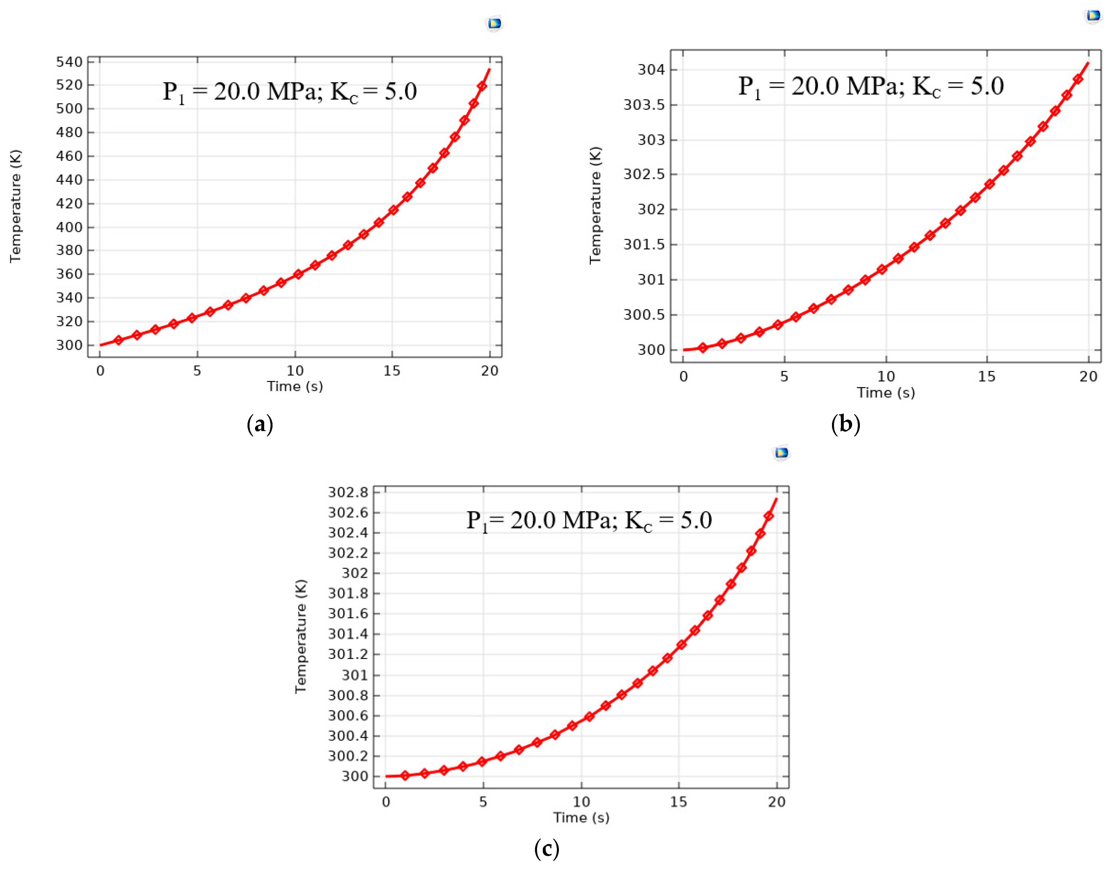
Figure 4 presents the temperature variation over time during a single compression stroke for hydrogen (a), the working fluid (b), and the chamber walls (c) at an initial pressure of 20.0 MPa and a compression coefficient of = 5.0.
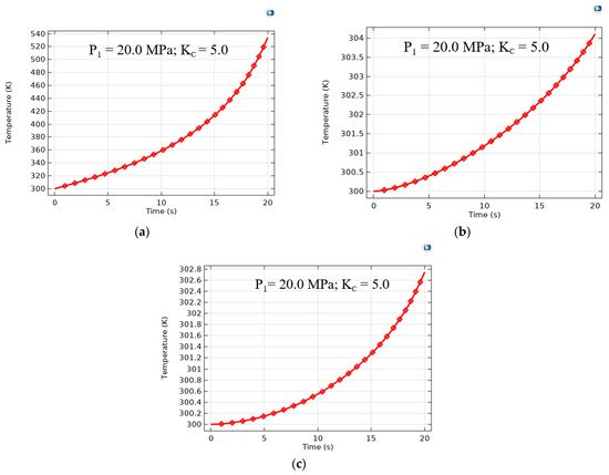
Figure 4.
Temperature increases during a single compression stroke at an initial hydrogen pressure of P1 = 20.0 MPa and a compression ratio of Kc = 5.0: (a) hydrogen, (b) working fluid, and (c) chamber walls.
The rapid temperature rise (Figure 4a) is attributed to adiabatic compression, where the reduction in volume leads to significant gas heating. The exponential-like trend indicates that as compression progresses, the temperature increase rate accelerates, particularly in the later stages. In contrast to hydrogen, the working fluid (Figure 4b) experiences only a moderate temperature rise, reaching around 304 K after 20 s. The relatively low warming is due to the high heat capacity of the liquid, which effectively absorbs heat from the compressed hydrogen. This demonstrates the fluid’s role in thermal regulation, helping to mitigate excessive temperature buildup in the system. The temperature of the stainless-steel chamber walls exhibits the slowest increase (Figure 4c), reaching only 302.8 K at the end of compression. The minimal temperature rise is attributed to the high thermal inertia and conductivity of the chamber material, which allows gradual heat dissipation. This suggests that the chamber structure plays a secondary role in heat absorption, with most heat being managed by the working fluid.
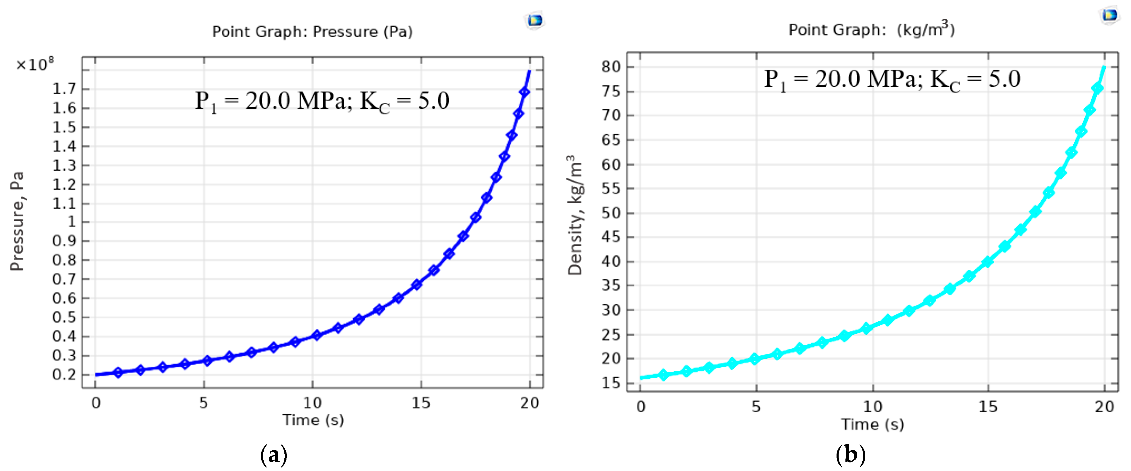
Figure 5 presents the variation of pressure (a) and density (b) of hydrogen over time during a single compression stroke at an initial pressure of = 20.0 MPa and a compression coefficient of = 5.0.
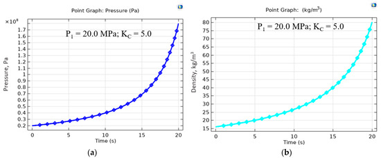
Figure 5.
Pressures change during a single compression stroke at = 20.0 MPa and = 5.0 (a). Density changes during a single compression stroke at = 20.0 and = 5.0 (b).
The hydrogen pressure exhibits a nonlinear increase. Under the accepted assumptions, where the media do not mix during the compression process, the calculated pressure value can reach approximately 170.0 MPa at the end of the 20-s compression stroke, as estimated using the ideal gas law for adiabatic compression and following the approach described in [58]. This behavior follows an exponential-like trend, indicating that as compression progresses, the pressure increase rate accelerates. The sharp rise in pressure in the later stages is a result of gas volume reduction, consistent with the principles of adiabatic compression.
However, it should be noted that under real conditions, due to the dynamic processes of the chamber cavity being filled with liquid, intensive cooling of the hydrogen occurs. As a result, the temperature of the hydrogen decreases and is determined by the temperature of the liquid, allowing the hydraulic compression process in the chamber to be considered close to isothermal [50].
Similarly, the hydrogen density shows a gradual increase in the initial phase, followed by an accelerated rise as compression continues. The final density reaches approximately = 80 kg/m3. This trend is directly correlated with the pressure increase, as hydrogen, being a compressible gas, experiences a significant rise in density when subjected to high-pressure conditions.
The model’s adaptability was tested under various initial pressure and volume conditions, demonstrating its flexibility across different operational scenarios. These findings highlight the importance of chamber design optimization and thermal management strategies to enhance performance. Further details on the computational model and the obtained data are available in [58].
This model was also used to investigate and analyze how different compression chamber geometries influence the final gas temperature during compression. By analyzing these effects, it is possible to estimate the energy consumption required to achieve a specific compression ratio while also considering the impact of compression speed on the process.
4. Dimension Scaling of the Hydrogen Compression Chamber
The scaling of the volume of the hydrogen compression chamber in a liquid piston hydrogen compression system is a critical design aspect that directly impacts efficiency, performance, and operational stability [56]. The chamber’s dimensions must be carefully selected to achieve the required compression ratio, ensuring the desired hydrogen pressure at the outlet. The size of the chamber plays a key role in this process, as it controls the movement of the liquid piston, influencing the chamber’s volume and compression efficiency [29].
Several factors determine the appropriate chamber dimensions. The initial volume must accommodate the required hydrogen intake while ensuring efficient compression [70,71]. Hydraulic system capacity must be sufficient to drive the liquid piston smoothly, while hydrogen flow rate requirements dictate the chamber size needed for optimal gas processing. Additionally, operating pressure and temperature affect gas density and compression characteristics, necessitating structural considerations for high-pressure durability [72]. The choice of materials influences chamber durability, weight, and thermal management, while optimized scaling helps minimize energy losses and mechanical wear [73,74].
To develop an efficient, reliable, and cost-effective hydrogen compression system suitable for industrial and refueling applications, careful adjustment of the compression chamber’s dimensions is crucial. This study focused on the impact of varying chamber geometries, particularly the working volume and size, on the final gas temperature during compression since the compression ratio is fixed at = 5.0, the investigation aimed to optimize energy usage by adjusting the compression speed while maintaining this ratio. By analyzing different chamber designs, we sought to enhance system efficiency and improve thermal management during the compression process.
The modeling results enable the assessment of extreme temperatures that might occur within the compression chamber, aiding in the design of optimal chamber dimensions to mitigate adverse thermodynamic effects.
The results of the numerical simulation are aimed at studying the energy costs and power consumption required for selecting a liquid pump drive motor and assessing the magnitude of the increase in the average gas temperature.
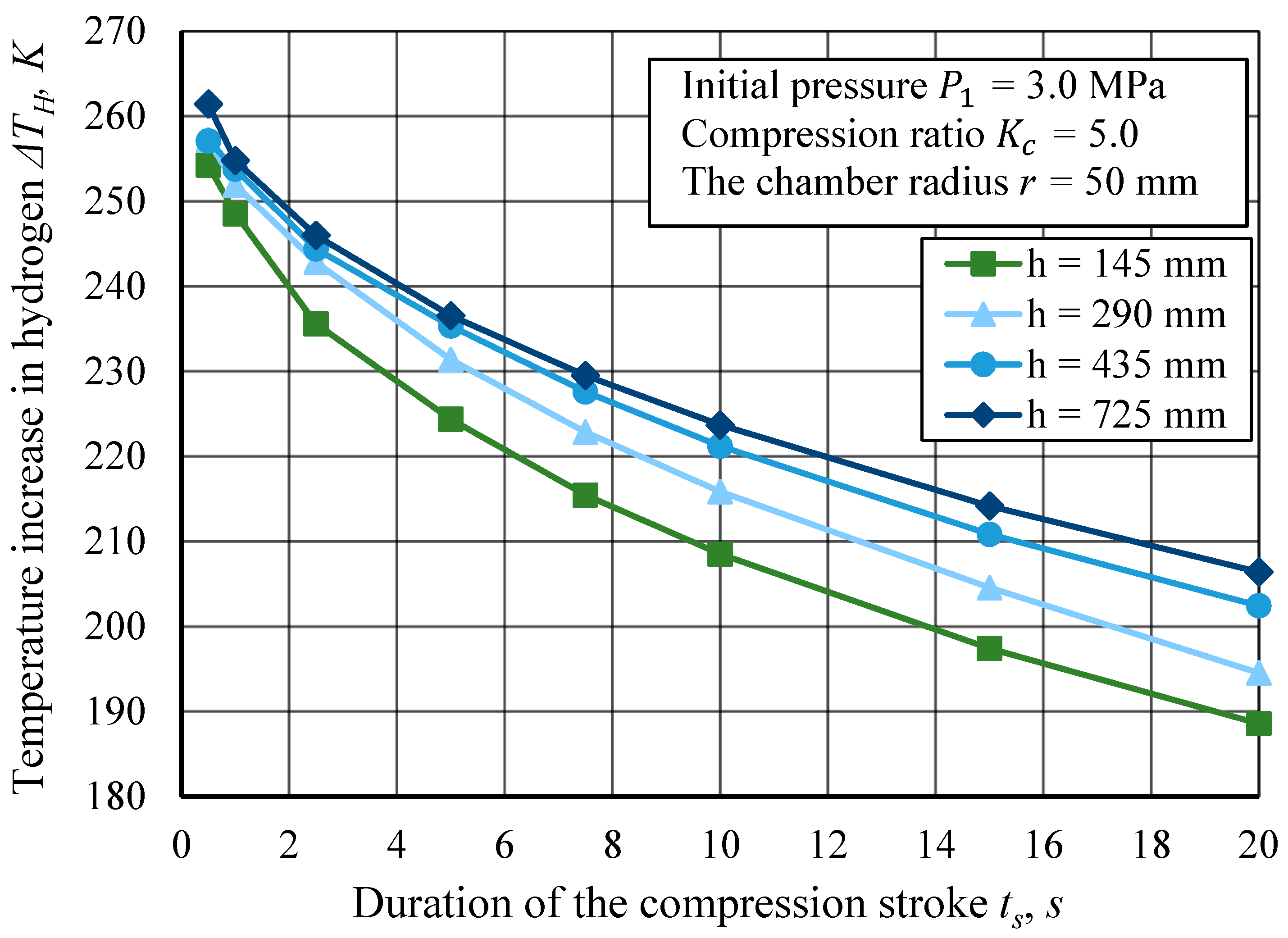
The compression chamber was modeled in various configurations, ranging in height from 145 mm to 725 mm, each with a constant wall thickness of 5 mm and an inner radius of 50 mm. The chamber heights were selected by exactly doubling, tripling, and quintupling the initial base model (145 mm) to enable a parametric study of the influence of chamber size on the thermodynamic behavior during hydrogen compression. Additionally, chamber radius variations from 50 mm to 125 mm were examined while maintaining a constant height of 145 mm. This analysis helps in understanding how changes in chamber height and radius influence the compression dynamics depending on the compression time, which is detailed in Figure 6, Figure 7, Figure 8 and Figure 9.
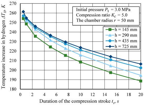
Figure 6.
Temperature increase in hydrogen for different compression stroke durations at an initial pressure of = 3.0 MPa, and a compression ratio of = 5.0. The compression chamber height varies from 145 mm to 725 mm for = 50 mm.

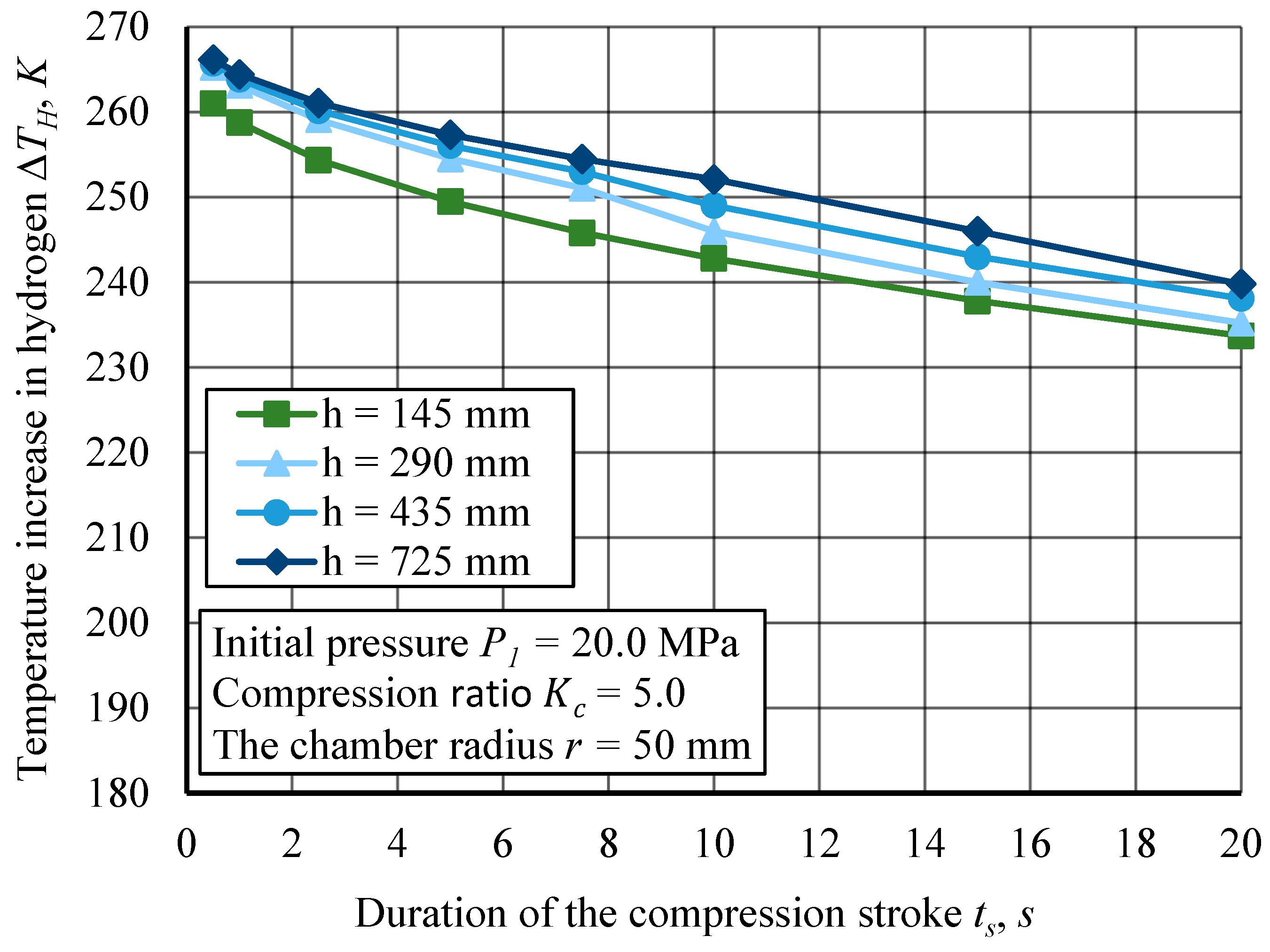
Figure 7.
The curves of temperature increase in hydrogen for different durations of the compression stroke ts at initial pressures = 20.0 MPa and compression ratio = 5.0. The compression chamber height varies from 145 mm to 725 mm for = 50 mm.

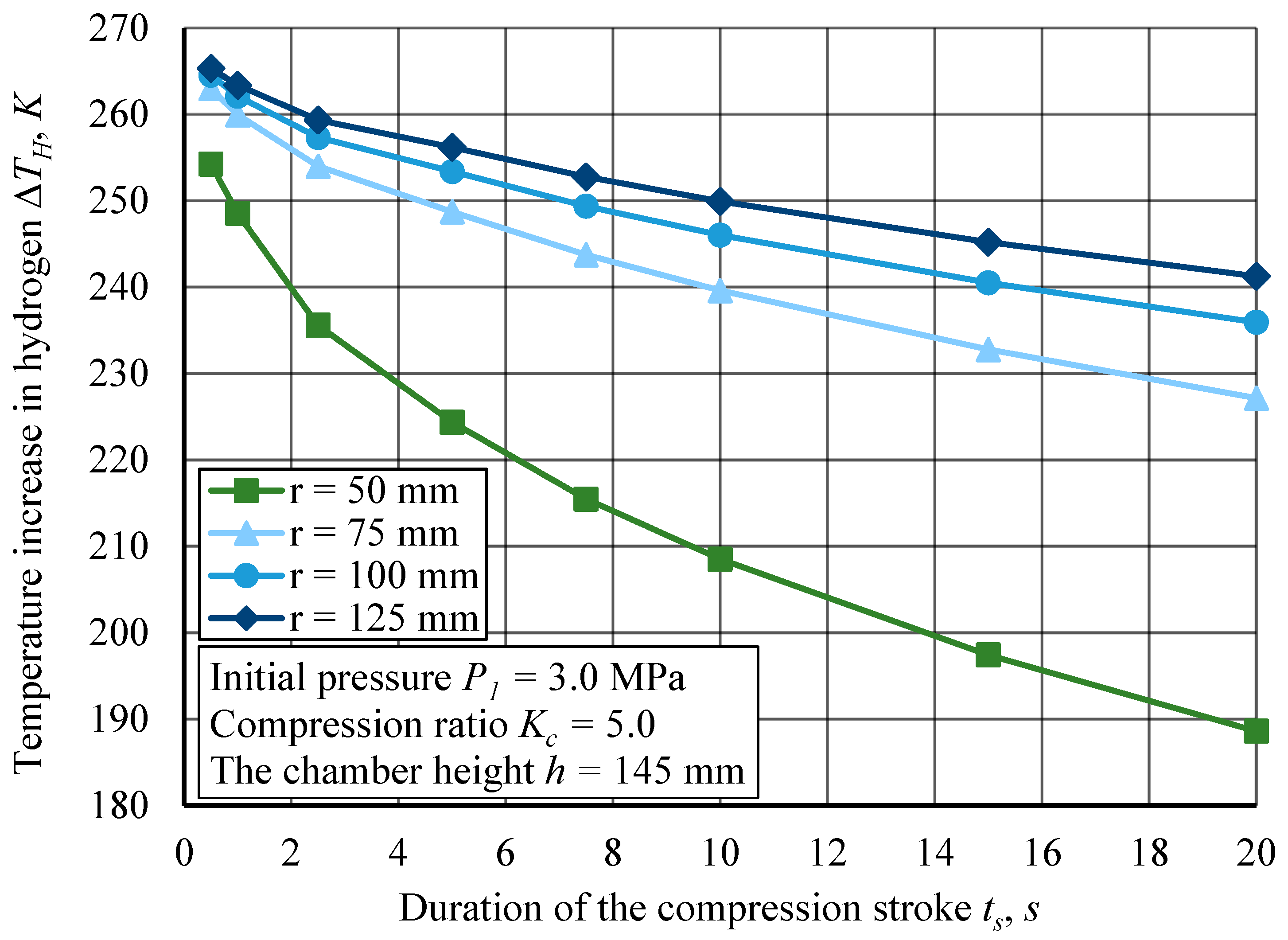
Figure 8.
The curves of temperature increase in hydrogen for different durations of the compression stroke at initial pressures = 3.0 MPa and compression ratio = 5.0. The compression chamber inner radius varies from 50 mm to 125 mm for = 145 mm.
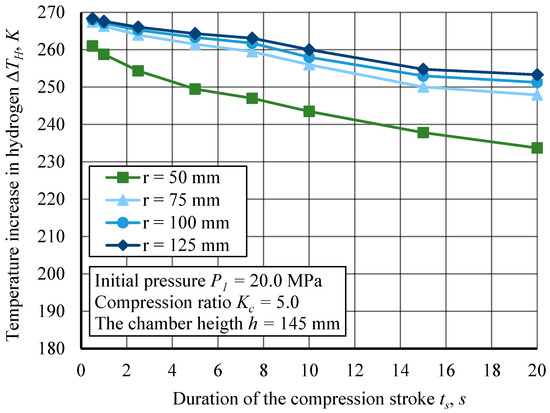
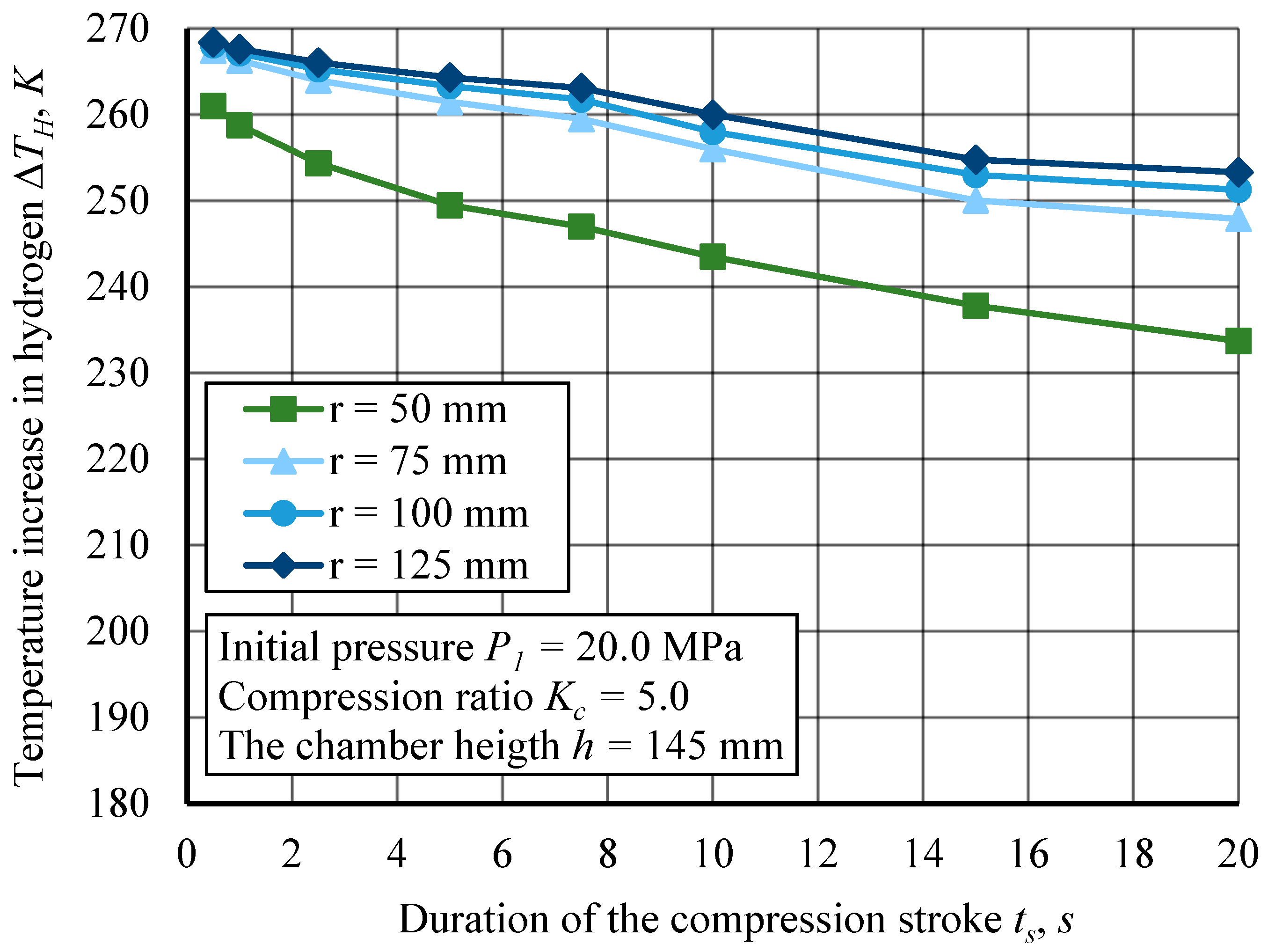
Figure 9.
The curves of temperature increase in hydrogen for different durations of the compression stroke at initial pressures = 20.0 MPa and compression ratio = 5.0. The compression chamber inner radius varies from 50 mm to 125 mm for = 145 mm.
Figure 6 presents the temperature increase in hydrogen as a function of the compression stroke duration for different compression chamber heights ( = 145 mm to = 725 mm). The initial pressure is = 3.0 MPa, and the compression ratio is fixed at = 5.0. The results illustrate how chamber geometry and compression duration affect the thermal behavior of hydrogen during compression. Shorter compression strokes lead to a higher temperature increase due to the rapid gas compression, which limits the time available for heat dissipation [58,75]. In contrast, longer compression strokes allow for better heat transfer to the chamber walls and working fluid, resulting in a lower final temperature. Additionally, as the chamber volume increases, the larger surface area relative to the gas volume facilitates more effective heat dissipation, leading to thermal stabilization, consistent with observations in [76,77].
Figure 7 presents the temperature increase in hydrogen as a function of the compression stroke duration or different compression chamber heights ( = 145 mm to = 725 mm). The initial pressure is = 20.0 MPa, and the compression ratio is fixed at = 5.0. Compared to cases with lower initial pressures ( = 3.0 MPa), higher initial pressures result in an overall higher temperature increase. This is expected due to the higher energy input required to compress hydrogen at elevated pressures, leading to greater thermal accumulation. However, the overall trend remains consistent, with temperature rise decreasing as compression stroke duration increases.
Figure 8 illustrates the temperature increase in hydrogen as a function of the compression stroke duration for different compression chamber inner radii ( = 50 mm to = 125 mm). The initial pressure is = 3.0 MPa, and the compression ratio is fixed at = 5.0. As the compression stroke duration increases, the temperature rise decreases across all chamber radii, confirming the expected relationship between compression speed and thermal accumulation.
Faster compression leads to less time for heat dissipation, whereas longer strokes allow more efficient thermal exchange, reducing the final gas temperature. The inner radius of the compression chamber significantly affects the temperature increase during compression. Smaller radii (e.g., = 50 mm) exhibit a lower temperature increase, while larger radii (e.g., = 125 mm) result in a larger temperature rise for the same compression duration.
This trend suggests that as the chamber radius increases, more energy is required to compress the gas, leading to greater heat accumulation. In contrast, smaller chamber radii allow for better heat dissipation due to a higher surface-area-to-volume ratio, which helps reduce temperature rise.
Figure 9 presents the temperature increase in hydrogen as a function of the compression stroke duration for different compression chamber inner radii ( = 50 mm to = 125 mm). Comparing these results to lower initial pressures (e.g., = 3.0 MPa from previous figures) confirms that higher initial pressure results in an overall higher temperature increase. This is expected, as greater energy input is needed to compress hydrogen at elevated pressures. Despite this, the overall trends remain consistent: smaller radii lead to lower temperature increases, and longer stroke durations reduce temperature rise.
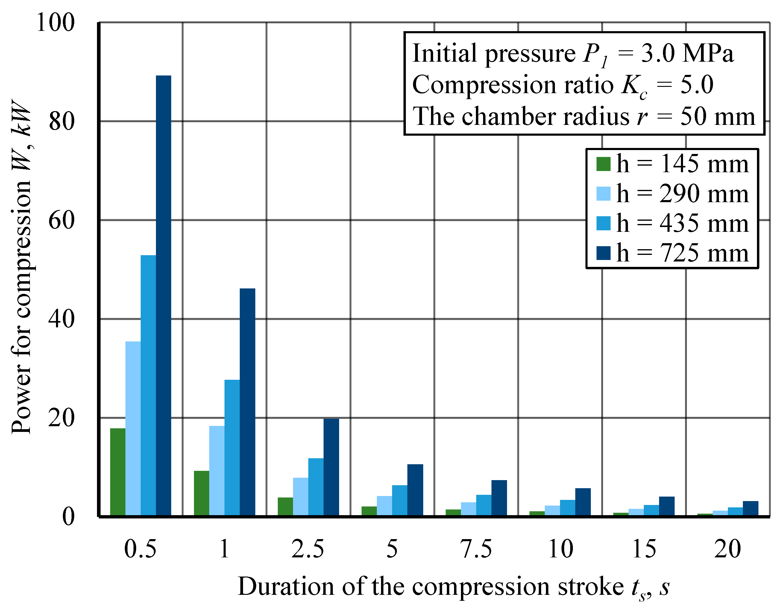
Also, curves of temperature increase in cylinder walls and liquid pistons were obtained for different durations of the compression stroke at initials pressure 3.0 and 20.0 MPa. Based on all data, energy consumption for one compression cycle, depending on the height and radius of the compression chamber, was calculated as shown in Figure 10, Figure 11, Figure 12 and Figure 13. Figure 10 and Figure 11 illustrate the relationship between the power required for compression and the duration of the compression stroke for initial pressures = 3.0 MPa and = 20.0 MPa depending on the compression chamber height changes. Figure 10 presents the power required for hydrogen compression as a function of the compression stroke duration for different compression chamber heights ( = 145 mm to = 725 mm). The initial pressure is = 3.0 MPa, and the compression ratio is fixed at = 5.0. The results illustrate the relationship between compression time, chamber height, and power demand during the compression process.
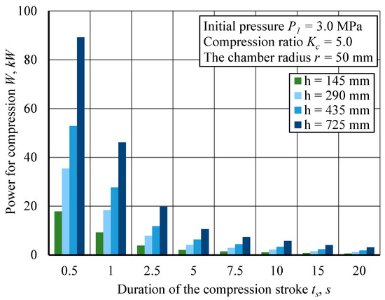
Figure 10.
The power required for hydrogen compression for different durations of the compression stroke at initial pressures = 3.0 MPa and compression ratio = 5.0 for different chamber heights for = 50 mm.
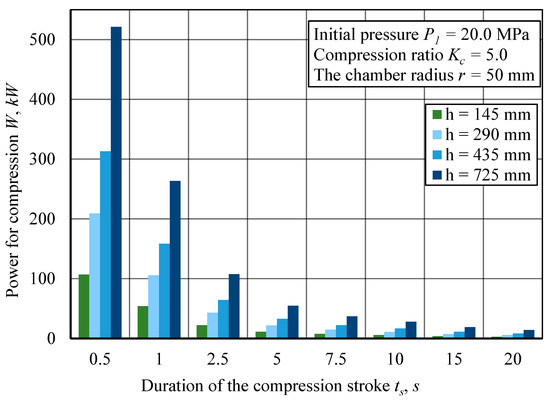
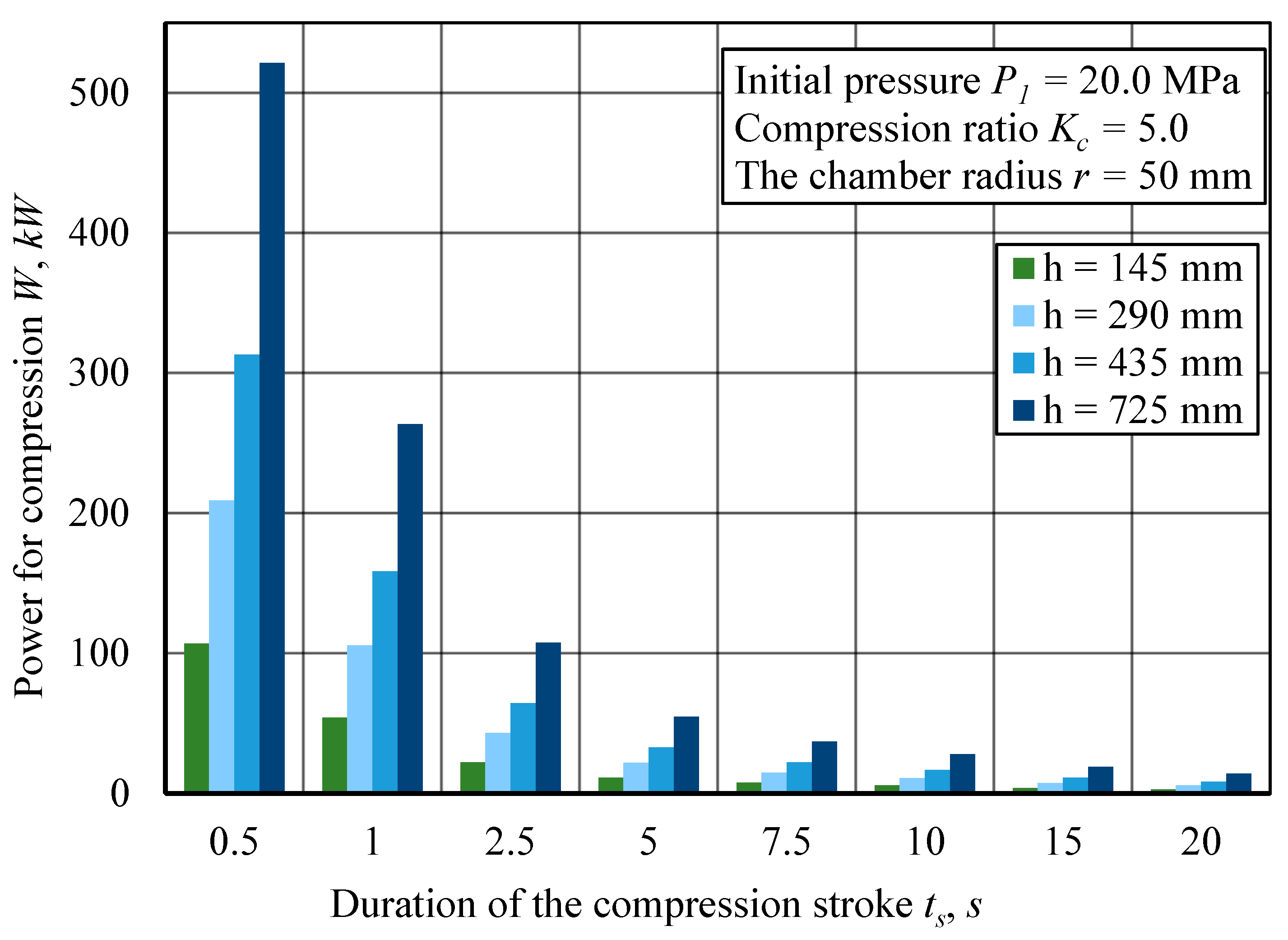
Figure 11.
The power required for hydrogen compression for different durations of the compression stroke at initial pressures = 20.0 MPa and compression ratio = 5.0 for different chamber heights for = 50 mm.
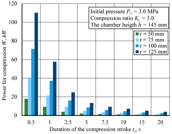
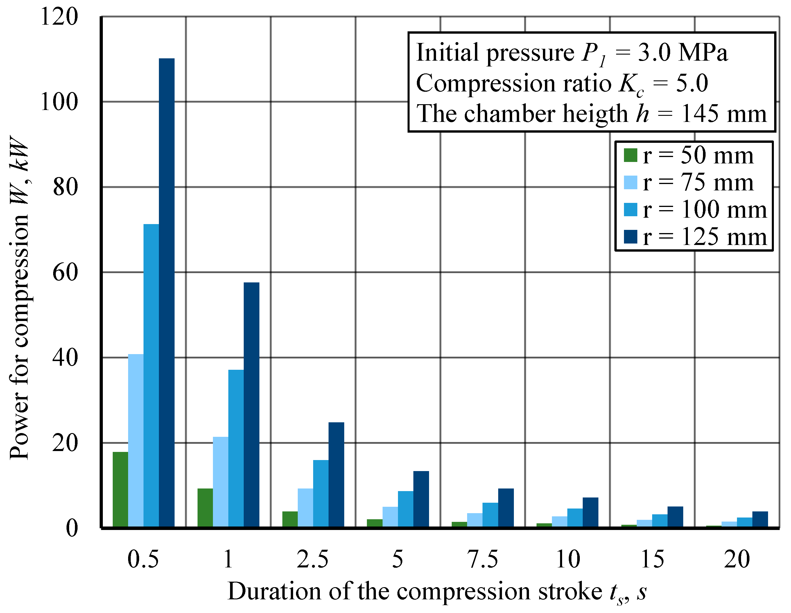
Figure 12.
The power required for hydrogen compression for different durations of the compression stroke at initial pressures = 3.0 MPa and compression ratio = 5.0 depending on chamber radius for = 145 mm.
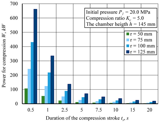
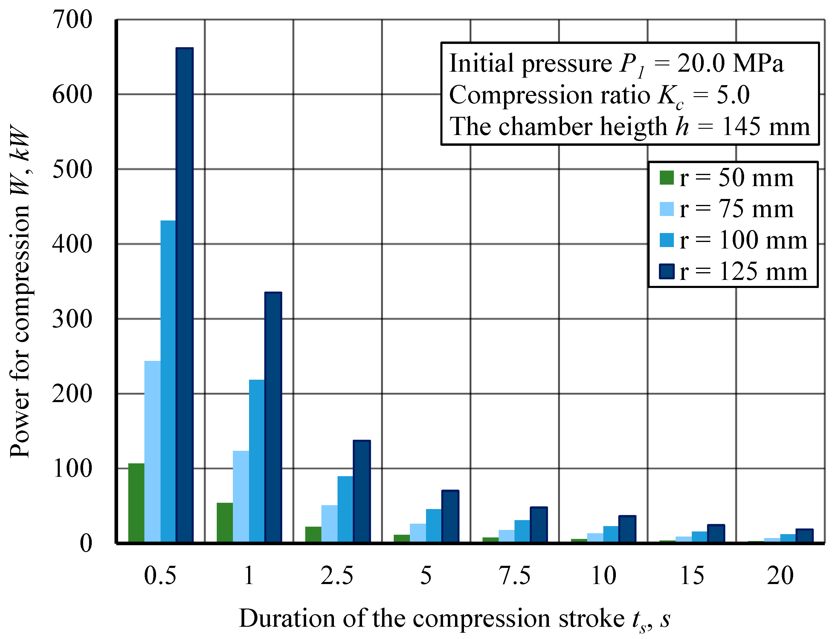
Figure 13.
The power required for hydrogen compression for different durations of the compression stroke at initial pressures = 20.0 MPa and compression ratio = 5.0 depending on the chamber’s radius for = 145 mm.
The data indicate a strong inverse relationship between compression stroke duration and power consumption. As the compression duration increases, the required power decreases sharply. This trend is expected, as rapid compression requires higher instantaneous energy input, whereas longer strokes distribute the energy demand over an extended period, reducing peak power requirements. The compression chamber height also affects power consumption. Smaller chamber heights (e.g., = 145 mm) require the highest power input, particularly for shorter compression strokes. Conversely, larger chamber heights (e.g., = 725 mm) exhibit a lower power demand across all compression durations.
Figure 11 illustrates the power required for hydrogen compression as a function of the compression stroke duration for different compression chamber heights ( = 145 mm to = 725 mm). The initial pressure is = 20.0 MPa, and the compression ratio is fixed at = 5.0. The results highlight the relationship between compression speed, chamber height, and power demand under higher initial pressure conditions compared to previous figures. The compression chamber height significantly influences power consumption. Larger chamber heights (e.g., = 725 mm) require the highest power input, especially at shorter compression durations, while smaller chamber heights (e.g., = 145 mm) require less power across all compression durations. This trend suggests that while larger chambers enable efficient compression at longer durations, they impose higher instantaneous energy demands at short durations due to the greater volume of compressed gas. A comparison with lower initial pressures (e.g., = 3.0 MPa from previous figures) confirms that higher initial pressure dramatically increases power demand. The power required in this case is several times higher than in the lower-pressure scenario, reflecting the higher energy input needed to achieve compression at elevated pressures.
Figure 12 and Figure 13 illustrate the relationship between the power required for compression and the duration of the compression stroke for initial pressure = 3.0 MPa and = 20.0 MPa depending on the compression chamber radius changes. The compression chamber’s inner radius significantly influences power demand. Larger radii (e.g., = 125 mm) require the highest power input, particularly at shorter compression strokes, while smaller radii (e.g., = 50 mm) require less power across all compression durations. This trend suggests that larger chamber volumes require more energy to compress the gas but offer a more gradual compression process at extended durations, reducing instantaneous energy spikes.
Figure 13 clearly shows that a comparison with lower initial pressures (e.g., = 3.0 MPa from Figure 12) confirms that higher initial pressure significantly increases power consumption. The power demand at = 20.0 MPa is several times greater than at = 3.0 MPa, emphasizing the higher energy input required for compressing hydrogen at elevated pressures. However, the overall trend remains consistent: shorter strokes require more power, and larger chamber radii intensify peak power demands at shorter durations.
At any given compression duration, the power required increases with chamber size, as larger volumes require more energy for compression. The results presented in the diagrams (Figure 10, Figure 11, Figure 12 and Figure 13) show that as the volume increases, the energy expenditure for compressing hydrogen increases correspondingly. Increases in either the height or radius dimensions equally affect the rise in power. However, in relative terms, the increase in power with an increase in volume is practically independent of the compression stroke duration.
Along with this, the compression chamber volume plays a crucial role in determining the temperature increase of hydrogen during the compression process.
Figure 14 shows that, under the condition of an initial pressure = 3.0 MPa and = 5.0, the chamber size has a significant effect on the temperature change at small volumes but eventually stabilizes. This trend suggests that while larger chamber volumes contribute to greater heat generation, their impact diminishes at higher volumes, indicating an upper thermal limit beyond which an increase in volume has little effect on temperature rise.
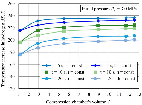
Figure 14.
Temperature increases in hydrogen as a function of compression chamber volume at an initial pressure of = 3.0 MPa for different compression stroke durations , with constant radius or height .
The slight scatter observed in the simulation data is attributed to numerical discretization effects. The general trend toward thermal stabilization at larger chamber volumes is driven by improved heat dissipation and extended compression times, which allow more efficient thermal regulation.
The influence of chamber geometry is also evident. For constant radius (), the temperature increase is generally higher compared to cases with constant height ( = const). This suggests that compression in chambers with larger height (fixed ) leads to greater heat accumulation, whereas wider chambers (fixed ) experience more effective heat dissipation due to increased surface area contact with the chamber walls.
Figure 15 shows that at higher initial pressures = 20.0 MPa, the overall temperature increase is significantly greater. This confirms that higher pressure levels amplify the effects of thermal accumulation, reinforcing the need for effective thermal management strategies in high-pressure hydrogen compression systems.
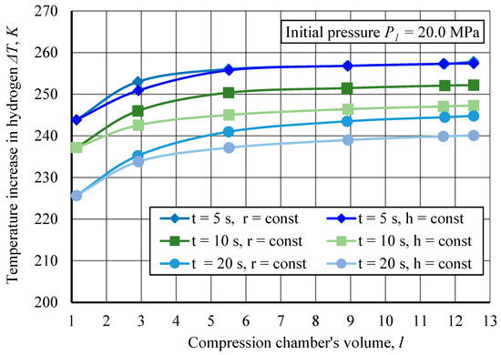
Figure 15.
Temperature increases in hydrogen as a function of compression chamber volume at an initial pressure of = 20.0 MPa for different compression stroke durations , with constant radius or height .
The presented results of thermodynamic process modeling allow for an assessment of the maximum temperatures that may occur in the compression chamber depending on its geometry. As the volume of the compression chamber increases, it is essential to evaluate the impact of these dimensions on thermodynamic processes.
The studies conducted to analyze the variation of hydrogen temperature as a function of the compression chamber’s height and radius provide insights into the dynamics of temperature increase under different compression conditions. As seen from the graphs, an increase in chamber volume leads to a rise in hydrogen temperature; however, at larger volumes, a tendency toward thermal stabilization is observed.
The scaling results, presented in Figure 6, Figure 7, Figure 8, Figure 9, Figure 10, Figure 11, Figure 12, Figure 13, Figure 14 and Figure 15, indicate that increasing the chamber volume significantly enhances the performance of the hydraulic compression system while only moderately raising the temperature of hydrogen. The analysis of the curves in Figure 14 and Figure 15 allows for estimating this temperature increase at 4–7% when the chamber volume is quadrupled from 3 to 12 L. The performance of the hydraulic compression system also depends on the duration of the compression stroke. When the compression process is accelerated from 20 to 10 s, the temperature of the hydrogen increases by 9%.
This highlights the necessity of optimizing chamber dimensions to ensure effective thermal management of the process.
5. Conclusions
This study investigated the thermodynamic behavior of hydrogen compression in a Liquid Piston Hydrogen Compressor through numerical simulations and scaling analysis. The results provide significant insights into the impact of chamber geometry, compression duration, and initial pressure on temperature distribution and energy efficiency.
Larger compression chamber volumes lead to higher peak temperatures, but beyond a certain volume, thermal stabilization occurs. Shorter compression strokes result in higher temperature increases, emphasizing the necessity of thermal management strategies to avoid excessive heating.
Chamber geometry plays a crucial role in energy consumption. Larger chamber radii require higher energy input for compression but improve heat dissipation, while smaller chamber radii result in lower energy demands but also lead to higher temperature accumulation due to a reduced heat dissipation area.
Higher initial pressures significantly increase temperature rise and energy consumption, reinforcing the need for efficient heat management solutions in high-pressure hydrogen storage. The overall pressure increase follows an exponential trend, with the highest pressure gains occurring in the later compression stages.
Optimizing compression chamber dimensions is critical for minimizing energy losses while maintaining operational efficiency. The scalability of LPHC systems makes them suitable for industrial applications, hydrogen refueling stations, and maritime sector integration, aligning with the goals of the green economy and sustainable energy transition.
Future research will focus on further detailing the thermal and mechanical characteristics of the compression chamber, particularly examining how variations in chamber wall thickness impact heat dissipation and the overall thermal management during the compression process. These investigations will contribute to the development of more efficient, durable, and safer hydrogen compression systems for industrial and energy applications. Furthermore, future work will include experimental investigations to validate and refine the numerical simulation results presented in this study, ensuring greater accuracy and practical applicability.
The practical implementation of liquid piston hydrogen compressors faces several challenges that must be addressed for large-scale adoption. Maintaining the stability of the liquid-gas interface during fast compression cycles is critical to avoid efficiency losses. Additionally, effective thermal management is required to control gas temperatures under high-speed, high-pressure operation. The long-term mechanical durability of the liquid piston system under repeated loading cycles also remains a key consideration for industrial applications. Addressing these challenges will be essential to fully realize the potential of LPHC technology in hydrogen energy infrastructure.
This study demonstrates a systematic approach to optimizing liquid piston hydrogen compression systems through CFD-based scaling analysis, providing new insights into the coupling between chamber geometry, compression dynamics, and thermal behavior. The results contribute to advancing the design principles for more energy-efficient and thermally stable hydrogen storage systems. Future research will explore multi-stage compression configurations, detailed investigation of fluid dynamics at the gas-liquid interface, and experimental validation to further refine the model and improve system reliability.
Author Contributions
Conceptualization, M.K., V.B. (Valerijs Bezrukovs) and V.B. (Vladislavs Bezrukovs); methodology, V.B. (Valerijs Bezrukovs), D.B. and M.B.; software, M.K. and N.G.; validation, V.B. (Valerijs Bezrukovs), V.B. (Vladislavs Bezrukovs) and A.I.P.; formal analysis, V.B. (Valerijs Bezrukovs); investigation, V.B. (Valerijs Bezrukovs), M.B. and N.G.; resources, M.K.; data curation, A.I.P.; writing—original draft preparation, M.K.; writing—review and editing, M.K. and A.I.P.; visualization, M.K. and D.B.; supervision, V.B. (Valerijs Bezrukovs); project administration, V.B. (Vladislavs Bezrukovs); funding acquisition, V.B. (Valerijs Bezrukovs). All authors have read and agreed to the published version of the manuscript.
Funding
This research has been financed by the HORIZON Coordination and Support Action project MarTe: Marine Technology Excellence Hub for Sustainable Blue Economy in the Baltics, project ID: 101186498, implemented in the Ventspils University of Applied Sciences.
Institutional Review Board Statement
Not applicable.
Informed Consent Statement
Not applicable.
Data Availability Statement
In order to obtain access to more information about the model used in this research, the reader can contact the corresponding author.
Acknowledgments
We extend our sincere gratitude to the Process Analysis and Research Centre (PAIC), Ltd., for their invaluable assistance with COMSOL modeling.
Conflicts of Interest
The authors declare no conflicts of interest.
Appendix A
The following tables present the key parameters used in the numerical simulations of the LPHC. These include initial conditions, thermophysical properties of hydrogen, liquid piston characteristics, and material properties of the stainless-steel chamber.
Table A1 lists the initial conditions, such as temperature, pressure, gas mass, and heat transfer coefficient.
Table A2 provides the thermodynamic properties of hydrogen, including specific heat capacities and the ratio of specific heat.
Table A3 summarizes the liquid piston properties, which influence heat transfer and system efficiency.
Table A4 presents the stainless-steel chamber properties, which are critical for assessing heat retention and structural performance.
These parameters ensure accurate modeling of hydrogen compression and thermal behavior.

Table A1.
Initial Conditions.
Table A1.
Initial Conditions.
| Parameter | Symbol | Value | Unit |
|---|---|---|---|
| Initial temperature (gas, working fluid, cylinder, air) | 300.0 | K | |
| Initial pressure | 3.0; 20.0 | MPa | |
| Volume | V | 1.14 | L |
| Gas mass in the chamber | 2.74 | g | |
| Heat transfer coefficient (chamber-air) | h | 30.0 | |
| Chamber mass | 2400 | g | |
| Chamber wall thickness | 5 | mm |
Table A2.
Hydrogen Properties.
Table A2.
Hydrogen Properties.
| Property | Symbol | Value | Unit |
|---|---|---|---|
| Molar mass | M | 2.016 | g/mol |
| Degrees of freedom | f | 5.0 | - |
| Ratio of specific heats | 1.4 | - | |
| Heat capacity at constant volume | 10,307.5 | ||
| Heat capacity at constant pressure | 14,429.6 |
Table A3.
Liquid Piston Properties.
Table A3.
Liquid Piston Properties.
| Property | Symbol | Value | Unit |
|---|---|---|---|
| Thermal conductivity | k | 0.4 | |
| Density | 918.0 | ||
| Heat capacity at constant pressure | 2060.0 | ||
| Dynamic viscosity | 0.005 | ||
| Ratio of specific heats | 1.0 | - |
Table A4.
Stainless Steel Chamber Properties.
Table A4.
Stainless Steel Chamber Properties.
| Property | Symbol | Value | Unit |
|---|---|---|---|
| Thermal conductivity | k | 45.0 | |
| Density | 7700.0 | ||
| Heat capacity at constant pressure | 800.0 |
References
- Schreyer, F.; Ueckerdt, F.; Pietzcker, R.; Rodrigues, R.; Rottoli, M.; Madeddu, S.; Pehl, M.; Hasse, R.; Luderer, G. Distinct roles of direct and indirect electrification in pathways to a renewables-dominated European energy system. One Earth 2024, 7, 226–241. [Google Scholar] [CrossRef]
- Merouani, S.; Hamdaoui, O. (Eds.) Hydrogen Production, Storage and Utilization: Thermochemical, Electrochemical, Sonochemical, Biological and Photocatalytic Processes; Walter de Gruyter GmbH & Co KG: Berlin, Germany, 2025. [Google Scholar]
- Khan, A.; Bradshaw, C.R. Quantitative comparison of the performance of vapor compression cycles with compressor vapor or liquid injection. Int. J. Refrig. 2023, 154, 386–394. [Google Scholar] [CrossRef]
- Rodríguez Castillo, C.A.; Yeter, B.; Li, S.; Brennan, F.; Collu, M. A critical review of challenges and opportunities for the design and operation of offshore structures supporting renewable hydrogen production, storage, and transport. Wind Energy Sci. 2024, 9, 533–554. [Google Scholar] [CrossRef]
- Calado, G.; Castro, R. Hydrogen Production from Offshore Wind Parks: Current Situation and Future Perspectives. Appl. Sci. 2021, 11, 5561. [Google Scholar] [CrossRef]
- Undertaking, C.H.J. Study on Hydrogen in Ports and Industrial Coastal Areas; European Commission: Brussels, Belgium, 2023. [Google Scholar]
- Balaji, R.K.; You, F. Sailing towards sustainability: Offshore wind’s green hydrogen potential for decarbonization in coastal USA. Energy Environ. Sci. 2024, 17, 6138–6156. [Google Scholar] [CrossRef]
- Semchukova, V.; Polemis, K.; Abdin, Z.; Solanki, B.; Cary, S. Hydrogen Infrastructure Analysis for the Port Applications; National Renewable Energy Laboratory (NREL): Golden, CO, USA, 2024. [CrossRef]
- International Energy Agency. Global Hydrogen Review 2024: Hydrogen Production; International Energy Agency: Paris, France, 2024; Available online: https://www.iea.org/reports/global-hydrogen-review-2024/hydrogen-production (accessed on 5 March 2025).
- Song, Y.; Chen, H.; Wang, X.; Weng, C.; Zou, K.; Wang, C.; Yuan, Y.; Yang, X.; Lin, W. Engineering Ir-based catalysts for high current density applications in proton exchange membrane water electrolyzers. Energy Environ. Sci. 2025, 18, 130–154. [Google Scholar] [CrossRef]
- Hou, J.; Yang, M. Green Hydrogen Production by Water Electrolysis; CRC Press: Boca Raton, FL, USA, 2025; p. 363. [Google Scholar]
- Younas, M.; Shafique, S.; Hafeez, A.; Javed, F.; Rehman, F. An overview of hydrogen production: Current status, potential, and challenges. Fuel 2022, 316, 123317. [Google Scholar] [CrossRef]
- Li, K.; Zhang, H.; Zheng, X.; Liu, C.; Chen, Q. Hydrogen Production by Water Electrolysis with Low Power and High Efficiency Based on Pre-Magnetic Polarization. Energies 2022, 15, 1878. [Google Scholar] [CrossRef]
- Taneja, S.; Jain, A.; Bhadoriya, Y. Green Hydrogen as a Clean Energy Resource and Its Applications as an Engine Fuel. Eng. Proc. 2023, 59, 159. [Google Scholar] [CrossRef]
- Bampaou, M.; Panopoulos, K.D. An overview of hydrogen valleys: Current status, challenges and their role in increased renewable energy penetration. Renew. Sustain. Energy Rev. 2025, 207, 114923. [Google Scholar] [CrossRef]
- Bhuiyan, M.M.H.; Siddique, Z. Hydrogen as an alternative fuel: A comprehensive review of challenges and opportunities in production, storage, and transportation. Int. J. Hydrogen Energy 2025, 102, 1026–1044. [Google Scholar] [CrossRef]
- Verma, A.; Malik, S.; Pal, M. Evaluating the Potential for Underground Hydrogen Storage (UHS) in Lithuania: A Review of Geological Viability and Storage Integrity. Appl. Sci. 2025, 15, 1614. [Google Scholar] [CrossRef]
- Naseem, K.; Qin, F.; Khalid, F.; Suo, G.; Zahra, T.; Chen, Z.; Javed, Z. Essential parts of hydrogen economy: Hydrogen production, storage, transportation and application. Renew. Sustain. Energy Rev. 2025, 210, 115196. [Google Scholar] [CrossRef]
- Rasul, M.G.; Hazrat, M.A.; Sattar, M.A.; Jahirul, M.I.; Shearer, M.J. The future of hydrogen: Challenges on production, storage and applications. Energy Convers. Manag. 2022, 272, 116326. [Google Scholar] [CrossRef]
- Shukla, A.K.; Gautam, R.; Chaudhary, S.; Srivastava, A.K.; Kumar, A.; Singh, S.; Maurya, P.K. Hydrogen energy: Addressing challenges and exploring future prospects. In Hydrogen Energy; CRC Press: Boca Raton, FL, USA, 2025; pp. 34–45. [Google Scholar]
- Bezrukovs, V.; Bezrukovs, V.; Konuhova, M.; Bezrukovs, D.; Berzins, A. Hydrogen hydraulic compression system for refuelling stations. Latv. J. Phys. Tech. Sci. 2022, 59, 96–105. [Google Scholar] [CrossRef]
- Dehshiri, S.S.H.; Firoozabadi, B. Hydrogen Penetration in Textile Industry: A Hybrid Renewable Energy System, Evolution Programming and Feasibility Analysis. Energy 2025, 318, 134785. [Google Scholar] [CrossRef]
- Röper, K.; Kunz, N.; Gast, L. Renewable hydrogen in industrial production: A bibliometric analysis of current and future applications. Int. J. Hydrogen Energy 2025, 98, 687–696. [Google Scholar] [CrossRef]
- Günaydın, Ö.F.; Topçu, S.; Aksoy, A. Hydrogen fuel cell vehicles: Overview and current status of hydrogen mobility. Int. J. Hydrogen Energy 2025, in press. [Google Scholar] [CrossRef]
- Orlova, S.; Mezeckis, N.; Vasudev, V.P.K. Compression of Hydrogen Gas for Energy Storage: A Review. Latv. J. Phys. Tech. Sci. 2023, 2, 4–16. [Google Scholar] [CrossRef]
- Halder, P.; Babaie, M.; Salek, F.; Shah, K.; Stevanovic, S.; Bodisco, T.A.; Zare, A. Performance, emissions and economic analyses of hydrogen fuel cell vehicles. Renew. Sustain. Energy Rev. 2024, 199, 114543. [Google Scholar] [CrossRef]
- Srinath, A.N.; Pena López, Á.; Miran Fashandi, S.A.; Lechat, S.; di Legge, G.; Nabavi, S.A.; Nikolaidis, T.; Jafari, S. Thermal Management System Architecture for Hydrogen-Powered Propulsion Technologies: Practices, Thematic Clusters, System Architectures, Future Challenges, and Opportunities. Energies 2022, 15, 304. [Google Scholar] [CrossRef]
- Le, T.T.; Sharma, P.; Bora, B.J.; Tran, V.D.; Truong, T.H.; Le, H.C.; Nguyen, P.Q.P. Fueling the future: A comprehensive review of hydrogen energy systems and their challenges. Int. J. Hydrogen Energy 2024, 54, 791–816. [Google Scholar] [CrossRef]
- Specklin, M.; Deligant, M.; Sapin, P.; Solis, M.; Wagner, M.; Markides, C.N.; Bakir, F. Numerical study of a liquid-piston compressor system for hydrogen applications. Appl. Therm. Eng. 2022, 216, 118946. [Google Scholar] [CrossRef]
- Huynh, V.T.; Kim, D. Numerical investigations of heat transfer enhancement in ionic liquid-piston compressor using cooling pipes. J. Vis. 2025, 28, 59–81. [Google Scholar] [CrossRef]
- Kermani, N.A.; Rokni, M. Heat transfer analysis of liquid piston compressor for hydrogen applications. Int. J. Hydrogen Energy 2015, 40, 11522–11529. [Google Scholar] [CrossRef]
- Curcio, E. Techno-economic analysis of hydrogen production: Costs, policies, and scalability in the transition to net-zero. Int. J. Hydrogen Energy 2025, 128, 473–487. [Google Scholar] [CrossRef]
- Mani, P.; Shenoy, S.; Sagayaraj, P.J.; Agamendran, N.; Son, S.; Bernaurdshaw, N.; Kim, H.-I.; Sekar, K. Scaling up of photocatalytic systems for large-scale hydrogen generation. Appl. Phys. Rev. 2025, 12, 011303. [Google Scholar] [CrossRef]
- Zou, J.; Han, N.; Yan, J.; Feng, Q.; Wang, Y.; Zhao, Z.; Fan, J.; Zeng, L.; Li, H.; Wang, H. Electrochemical compression technologies for high-pressure hydrogen: Current status, challenges and perspective. Electrochem. Energy Rev. 2020, 3, 690–729. [Google Scholar] [CrossRef]
- Moore, J.; Durham, J.; Eijk, A.; Karakas, E.; Kurz, R.; Lesak, J.; McBain, M.; McCalley, P.; Moroz, L.; Mohamed, Z.; et al. Compressors and expanders. In Machinery and Energy Systems for the Hydrogen Economy; Elsevier: Amsterdam, The Netherlands, 2022; pp. 333–424. [Google Scholar] [CrossRef]
- Li, J.; Han, Z.; Liu, J.; Tian, W.; Wu, X.; Fang, J.; Zuo, Z. Study on the Influence of Key Parameters on the Gas Production Efficiency of 70 MPa Hydrogen Diaphragm Compressor. J. Xihua Univ. (Nat. Sci. Ed.) 2025, 44, 190–198. [Google Scholar] [CrossRef]
- Xiong, Z.; Liu, Y.; Cai, Y.; Chang, W.; Wang, Z.; Li, Z.; Peng, S. Research on the effect of green hydrogen blending on natural gas centrifugal compressor performance. Renew. Energy 2025, 242, 122378. [Google Scholar] [CrossRef]
- Genovese, M.; Piraino, F.; Kovač, A.; Marciuš, D.; Pagnotta, L.; Fragiacomo, P. Integration of hydrogen compressors and turbines into current and future hydrogen infrastructure. J. Power Sources 2025, 629, 235965. [Google Scholar] [CrossRef]
- Singh, U.R.; Bhogilla, S.S.; Sou, H.; Itoko, S.; Tolj, I. Performance evaluation of hybrid compressors for hydrogen storage and refuelling stations. J. Energy Storage 2025, 114, 115778. [Google Scholar] [CrossRef]
- Askri, F.; Mellouli, S.; Alqahtani, T.; Algarni, S.; El Awadi, G.A. Performance enhancement of metal hydride hydrogen compressors using a novel operating procedure. Appl. Therm. Eng. 2023, 233, 121178. [Google Scholar] [CrossRef]
- Dashbabu, D.; Kumar, E.A.; Jain, I.P. Thermodynamic analysis of a metal hydride hydrogen compressor with aluminium substituted LaNi5 hydrides. Int. J. Hydrogen Energy 2023, 48, 37886–37897. [Google Scholar] [CrossRef]
- Caponetto, R.; Privitera, E.; Mirone, G.; Matera, F. Structural Analysis of Electrochemical Hydrogen Compressor End-Plates for High-Pressure Applications. Energies 2022, 15, 5823. [Google Scholar] [CrossRef]
- Borisov, N.; Mladenova, B.; Borisov, G.; Slavcheva, E. Catalytic Activity of Pt/Pd Mono- and Bimetallic Catalysts in Electrochemical Hydrogen Pump/Compressor. Inorganics 2025, 13, 48. [Google Scholar] [CrossRef]
- Gong, M.; Jin, C.; Na, Y. Minimizing Area-Specific Resistance of Electrochemical Hydrogen Compressor under Various Operating Conditions Using Unsteady 3D Single-Channel Model. Membranes 2023, 13, 555. [Google Scholar] [CrossRef]
- Sdanghi, G.; Maranzana, G.; Celzard, A.; Fierro, V. Review of the current technologies and performances of hydrogen compression for stationary and automotive applications. Renew. Sustain. Energy Rev. 2019, 102, 150–170. [Google Scholar] [CrossRef]
- Chalkiadakis, N.; Stubos, A.; Stamatakis, E.; Zoulias, E.; Tsoutsos, T. A review on hydrogen compression methods for hydrogen refuelling stations. Hydrog. Electr. Veh. 2023, Chapter 3, 47–73. [Google Scholar] [CrossRef]
- Pereira, J.; Souza, R.; Oliveira, J.; Moita, A. Hydrogen Production, Transporting and Storage Processes—A Brief Review. Clean Technol. 2024, 6, 1260–1313. [Google Scholar] [CrossRef]
- Sdanghi, G.; Maranzana, G.; Celzard, A.; Fierro, V. Towards non-mechanical hybrid hydrogen compression for decentralized hydrogen facilities. Energies 2020, 13, 3145. [Google Scholar] [CrossRef]
- Zhou, H.; Ooi, K.T.; Dong, P.; Yang, Z.; Zhou, S.; Zhao, S. Dynamic and energy analysis of a liquid piston hydrogen compressor. Int. J. Hydrogen Energy 2023, 48, 20694–20704. [Google Scholar] [CrossRef]
- Bezrukovs, V.; Bezrukovs, V.; Konuhova, M.; Bezrukovs, D.; Kaldre, I.; Berzins, A. R&D of a Hydraulic Hydrogen Compression System for Refuelling Stations. Latv. J. Phys. Tech. Sci. 2023, 60, 21–39. [Google Scholar] [CrossRef]
- Humphrey, H.A. An internal-combustion pump, and other applications of a new principle. Proc. Inst. Mech. Eng. 1909, 77, 1075–1200. [Google Scholar] [CrossRef]
- Joyce, N.G. The Humphrey pump. Appropr. Technol. 1978, 5, 27–29. [Google Scholar]
- Bezrukovs, V.; Bezrukovs, D.; Konuhova, M.; Berzins, A. Hydrogen Hydraulic Compression Device. WO2024047390A1, 7 March 2024. [Google Scholar]
- Guo, Y.; Wang, Q.; Ren, S.; Zhang, M.; Peng, X. Numerical investigation on the wave transformation in the ionic liquid compressor for the application in hydrogen refuelling stations. Int. J. Hydrogen Energy 2023, 48, 13955–13971. [Google Scholar] [CrossRef]
- Van de Ven, J.D.; Li, P.Y. Liquid piston gas compression. Appl. Energy 2009, 86, 2183–2191. [Google Scholar] [CrossRef]
- Zhou, H.; Dong, P.; Zhu, S.; Li, S.; Zhao, S.; Wang, Y. Design and theoretical analysis of a liquid piston hydrogen compressor. J. Energy Storage 2021, 41, 102861. [Google Scholar] [CrossRef]
- Zhou, H.; Liu, M.; Dong, P.; Liu, D.; Guo, Y.; Zhao, S. Theoretical study of the dynamic characteristics of a self-commutating liquid piston hydrogen compressor. Int. J. Hydrogen Energy 2023, 48, 5999–6009. [Google Scholar] [CrossRef]
- Bezrukovs, V.; Bezrukovs, V.; Konuhova, M.; Bezrukovs, D.; Kaldre, I.; Popov, A.I. Numerical Simulations of Thermodynamic Processes in the Chamber of a Liquid Piston Compressor for Hydrogen Applications. Technologies 2024, 12, 266. [Google Scholar] [CrossRef]
- Khan, M.A.; Young, C.; Mackinnon, C.; Layzell, D. The techno-economics of hydrogen compression. Transit. Accel. Tech. Briefs 2021, 1, 1–36. [Google Scholar]
- Dornheim, M.; Baetck, L.; Akiba, E.; Ares, J.R.; Autrey, T.; Barale, J.; Baricco, M.; Brooks, K.; Chalkiadakis, N.; Charbonnier, V.; et al. Research and development of hydrogen carrier based solutions for hydrogen compression and storage. Prog. Energy 2022, 4, 042005. [Google Scholar] [CrossRef]
- Zhou, H.; Ooi, K.T.; Sun, H.; Dong, P.; Fan, S.; Zhao, S. Parameter Optimization Study of Porous Media for Enhanced Heat Transfer in Liquid Piston-Type Hydrogen Compressor based on SOBP-SO Algorithm. Renew. Energy 2025, 242, 122505. [Google Scholar] [CrossRef]
- Prokopou, G.I.; Faust, J.M.; Mitsos, A.; Bongartz, D. Cost-optimal design and operation of hydrogen refueling stations with mechanical and electrochemical hydrogen compressors. Comput. Chem. Eng. 2025, 192, 108862. [Google Scholar] [CrossRef]
- Bezrukovs, V.; Bezrukovs, D.; Konuhova, M.; Berzins, A. Hydrogen Hydraulic Compression Device. European Patent No. EP4352368B1, 9 April 2025. [Google Scholar]
- Leonard, L.; Can, T.; Michelle, T. Hydrogen Compression Boosting the Hydrogen Economy. 2022. Available online: https://www.recip.org/wp-content/uploads/2023/01/2022-EFRC-WhitePaper-Hydrogen-Compression.pdf (accessed on 5 March 2025).
- Lototskyy, M.; Linkov, V. Thermally driven hydrogen compression using metal hydrides. Int. J. Energy Res. 2022, 46, 22049–22069. [Google Scholar] [CrossRef]
- Šabacká, P.; Maxa, J.; Bayer, R.; Binar, T.; Bača, P.; Švecová, J.; Talár, J.; Vlkovský, M. An Experimental and Numerical Analysis of the Influence of Surface Roughness on Supersonic Flow in a Nozzle Under Atmospheric and Low-Pressure Conditions. Technologies 2025, 13, 160. [Google Scholar] [CrossRef]
- Khan, A.; Irfan, M.; Niazi, U.M.; Shah, I.; Legutko, S.; Rahman, S.; Alwadie, A.S.; Jalalah, M.; Glowacz, A.; Khan, M.K.A. Centrifugal Compressor Stall Control by the Application of Engineered Surface Roughness on Diffuser Shroud Using Numerical Simulations. Materials 2021, 14, 2033. [Google Scholar] [CrossRef]
- Ye, J.; Zhao, Z.; Zheng, J.; Salem, S.; Yu, J.; Cui, J.; Jiao, X. Transient flow characteristic of high-pressure hydrogen gas in check valve during the opening process. Energies 2020, 13, 4222. [Google Scholar] [CrossRef]
- Guo, Y.; Tang, Y.; Cao, J.; Diao, A.; Peng, X. Control Strategies for Piston Trajectory in Ionic Compressors for Hydrogen Storage. Appl. Sci. 2023, 13, 11759. [Google Scholar] [CrossRef]
- Franco, A.; Giovannini, C. Hydrogen Gas Compression for Efficient Storage: Balancing Energy and Increasing Density. Hydrogen 2024, 5, 293–311. [Google Scholar] [CrossRef]
- Knop, Vincent. “Life Cycle Analysis of Hydrogen Compression.” A World of Energy. 2022. Available online: https://www.awoe.net/Hydrogen-Compression-LCA.html (accessed on 5 March 2025).
- Lanz, A.; Heffel, J.; Messer, C. Hydrogen Fuel Cell Engines and Related Technologies; Energy Technology Training Center, College of the Desert: Palm Desert, CA, USA, 2001. [Google Scholar]
- Dwivedi, S.K.; Vishwakarma, M. Hydrogen embrittlement in different materials: A review. Int. J. Hydrogen Energy 2018, 43, 21603–21616. [Google Scholar] [CrossRef]
- Nachtane, M.; Tarfaoui, M.; Abichou, M.A.; Vetcher, A.; Rouway, M.; Aâmir, A.; Mouadili, H.; Laaouidi, H.; Naanani, H. An Overview of the Recent Advances in Composite Materials and Artificial Intelligence for Hydrogen Storage Vessels Design. J. Compos. Sci. 2023, 7, 119. [Google Scholar] [CrossRef]
- Xue, L.; Deng, J.; Wang, X.; Wang, Z.; Liu, B. Numerical Simulation and Optimization of Rapid Filling of High-Pressure Hydrogen Storage Cylinder. Energies 2022, 15, 5189. [Google Scholar] [CrossRef]
- Ursua, A.; Gandia, L.M.; Sanchis, P. Hydrogen production from water electrolysis: Current status and future trends. Proc. IEEE 2011, 100, 410–426. [Google Scholar] [CrossRef]
- Züttel, A.; Remhof, A.; Borgschulte, A.; Friedrichs, O. Hydrogen: The future energy carrier. Philos. Trans. R. Soc. A Math. Phys. Eng. Sci. 2010, 368, 3329–3342. [Google Scholar] [CrossRef]

Disclaimer/Publisher’s Note: The statements, opinions and data contained in all publications are solely those of the individual author(s) and contributor(s) and not of MDPI and/or the editor(s). MDPI and/or the editor(s) disclaim responsibility for any injury to people or property resulting from any ideas, methods, instructions or products referred to in the content. |
© 2025 by the authors. Licensee MDPI, Basel, Switzerland. This article is an open access article distributed under the terms and conditions of the Creative Commons Attribution (CC BY) license (https://creativecommons.org/licenses/by/4.0/).