Article

The Electromechanical Modeling and Parametric Analysis of a Piezoelectric Vibration Energy Harvester for Induction Motors

by
Moisés Vázquez-Toledo
1,
Arxel de León
2,
Francisco López-Huerta
3,
Pedro J. García-Ramírez
4,
Ernesto A. Elvira-Hernández
5 and
Agustín L. Herrera-May
1,6,*
1
Faculty of Construction and Habitat Engineering, Universidad Veracruzana, Boca del Río 94294, Veracruz, Mexico
2
SECIHTI-Centro de Investigación en Química Aplicada, Saltillo 25294, Coahuila, Mexico
3
Faculty of Electrical and Electronic Engineering, Universidad Veracruzana, Boca del Río 94294, Veracruz, Mexico
4
Institute of Engineering, Universidad Veracruzana, Boca del Río 94294, Veracruz, Mexico
5
Faculty of Mechanical Engineering and Naval Sciences, Universidad Veracruzana, Boca del Río 94294, Veracruz, Mexico
6
Micro and Nanotechnology Research Center, Universidad Veracruzana, Boca del Río 94294, Veracruz, Mexico
*
Author to whom correspondence should be addressed.
Technologies 2025, 13(5), 194; https://doi.org/10.3390/technologies13050194
Submission received: 19 March 2025 / Revised: 3 May 2025 / Accepted: 8 May 2025 / Published: 10 May 2025
(This article belongs to the Special Issue Technological Advances in Science, Medicine, and Engineering 2024)

Abstract

:
Industrial motors generate vibration energy that can be converted into electrical energy using piezoelectric vibration energy harvesters (pVEHs). These energy harvesters can power devices or function as self-powered sensors. However, optimal electromechanical designs of pVEHs are required to improve their output performance under different vibration frequency and amplitude conditions. To address this challenge, we performed the electromechanical modeling of a multilayer pVEH that harvests vibration energy from induction electric motors at frequencies close to 30 Hz. In addition, a parametric analysis of the geometry of the multilayer piezoelectric device was conducted to optimize its deflection and output voltage, considering the substrate length, piezoelectric patch position, and dimensions of the central hole. Our analytical model predicted the deflection and first bending resonant frequency of the piezoelectric device, with good agreement with predictions from finite element method (FEM) models. The proposed piezoelectric device achieved an output voltage of 143.2 V and an output power of 3.2 mW with an optimal resistance of 6309.5 kΩ. Also, the principal stresses of the pVEH were assessed using linear trend analysis, finding a safe operating range up to an acceleration of 0.7 g. The electromechanical design of the pVEH allowed for effective synchronization with the vibration frequency of an induction electric motor. This energy harvester has a potential application in industrial electric motors to transform their vibration energy into electrical energy to power sensors.

Graphical Abstract

1. Introduction

Electric motors are essential in industrial processes, converting electrical energy into mechanical power for applications such as fluid motion, material handling, air compression, refrigeration, and boiler operation [1,2]. Despite the high efficiency (85–97%) of electrical motors [3,4,5], a significant portion of their input energy is lost as heat, stray magnetic flux, and mechanical vibrations. These energy types can be harvested to power devices within predictive maintenance systems for electric motors in industrial environments. These systems can be integrated with Internet of Things (IoT) technology to monitor equipment health and prevent unexpected failures [6,7,8]. However, their implementation in the industrial sector has several challenges, particularly in confined spaces and hazardous atmospheres [9,10,11]. Furthermore, the use of sensor networks is often impractical due to safety and spatial limitations, while their reliance on batteries increases costs and environmental damage [12,13,14]. To address these challenges, alternative green energy sources are needed to power industrial monitoring system devices. For instance, the stray magnetic flux generated by electric motors can be harnessed using coils or current transformers [15,16]. Although these transformers output energy levels higher than 1 mW [17], their practical implementation is often constrained by limited access to power cables in industrial facilities. Also, coils require custom manufacturing and precise alignment. Thus, mechanical vibrations can affect coils’ stability and performance. On the other hand, the stray magnetic fluxes harvested from electric motors depend on the proximity to the magnetic cores of the motors [18,19,20,21,22], which complicates their application in industrial environments.
Although stray magnetic flux has been explored as an energy source in electric motors, piezoelectric vibration energy harvesters (pVEHs) have emerged as promising devices to convert mechanical vibrations into electrical energy [23,24,25]. These piezoelectric devices can be used in electric motors to harness mechanical vibrations and transform them into clean electrical energy, which has a longer service time than electrochemical batteries [24,26]. Moreover, piezoelectric energy harvesters offer compact and non-intrusive designs that are easier to integrate into motor housings employing conventional adhesives. These advantages mean that pVEHs can be leveraged as a robust and scalable solution for self-powered monitoring systems for electric motors. Based on this device type, Yadav and Kumar [27] reported the use of a piezoelectric system with PZT diaphragms to collect vibrational energy, achieving a yield of up to 373.44 µW under controlled conditions. However, most piezoelectric energy harvesters are designed to operate at high frequencies and do not match the typical vibration frequencies of electric motors. Commonly, industrial motors generate vibrations close to 30 Hz, 60 Hz, and 120 Hz. However, many pVEHs have been developed to work at higher frequencies, limiting their use in electric motors. For instance, various energy harvesters are fabricated for specialized applications, such as biomedical devices, aerospace systems, and microelectromechanical system (MEMS) technologies, rather than for the industrial sector. In the context of MEMS technology, Prušáková et al. [28] presented a PVEH resonating at 592 Hz, while Wang and Du [29] reported a pVEH operating at a frequency close to 1300.1 Hz. However, these frequencies are higher than those of the vibrations generated by typical electric motors. On the other hand, Elvira-Hernández et al. [30] proposed a pVEH with a resonant frequency of 60.3 Hz, which is closer to the vibration frequencies of electrical motors. However, this energy harvester was designed for application in air conditioning systems in office buildings, where vibrations have stable behavior and a low amplitude. Thus, this piezoelectric device is not suitable to harvest the variable vibration energy produced by industrial electric motors.
Generally, industrial electric motors produce vibrations with large amplitudes and fluctuations, which cause mechanical wear. To scavenge the energy produced due to these strong vibrations, electromechanical designs of pVEHs must ensure their safe mechanical operation and optimal electrical performance for the selected electric motor. Therefore, the design of robust resonant structures for piezoelectric energy harvesters can increase their mechanical strength and lifetime in the presence of strong vibrations. Recent advances in piezoelectric energy harvesters have shown a trend toward internal integration within rotating machinery, rather than relying on external mounting. This internal integration offers advantages such as enhanced energy harvesting due to a better proximity to the vibration source, improved robustness against harsh environmental conditions, and minimized signal loss. For instance, Qin et al. [31] introduced an innovative hybrid squirrel cage structure that was composed of triboelectric and piezoelectric mechanisms. This prototype demonstrated advanced energy harvesting and sensing capabilities, achieving a combined power output of up to 100 μW at a rotational speed of 15 Hz. Xiao et al. [32] reported a smart bearing incorporating a segmented-electrode piezoelectric transducer directly within its structure, facilitating multidirectional vibration sensing and fault diagnosis. Similarly, Safian et al. [33] demonstrated that an embedded piezoelectric transducer could generate dynamic voltage signals of approximately ±3 V under an 800 N load at 1000 rpm. Zhang et al. [34] reported the electromechanical design of a pVEH formed of an arc-shaped piezoelectric sheet to harvest the energy of a rolling bearing and bearing pedestal. This device could produce 25 V of RMS voltage and 60 μW to 131 μW of RMS power under rotational speeds of between 600 rpm and 1200 rpm. However, this electromechanical model is limited to energy harvesters with arc-shaped piezoelectric sheets. In opposition to embedded pVEHs, the external mounting of piezoelectric energy harvesters on industrial electric motors offers ease of installation, low-cost maintenance, simple signal processing, and adaptability across different motor types without requiring modifications to their internal structures. The external integration of pVEHs simplifies the replacement of electric motors and minimizes disruptions to their mechanical integrity. Moreover, external energy harvesters are less invasive, scalable, and particularly well suited for applications where operational continuity and cost-effectiveness are critical considerations.
Herein, we present the electromechanical modeling of a multilayer pVEH that can harvest vibration energy from induction electric motors to transform it into clean electrical energy. This device is designed to operate under low-frequency vibrations to match those from typical induction electric motors (~30 Hz). In addition, a parametric analysis of the multilayer geometry of the piezoelectric device was performed to optimize its electrical performance, considering the substrate length, the piezoelectric patch position, and the dimensions of a central hole in the piezoelectric layer. For this purpose, finite element method (FEM) models of the pVEH were created using COMSOL Multiphysic ® version 5.5 software. The results obtained from analytical modeling showed good agreement with those from the FEM simulations. The proposed device can achieve an output voltage of 143.2 V and an output power of 3.2 mW with an optimal resistance of 6309.5 kΩ. This piezoelectric energy harvester has a robust transduction mechanism with simple signal processing that allows for its safe operation in induction electric motors, providing a renewable energy source for powering sensors in potential industrial monitoring systems. Thus, the proposed electromechanical model can be used to design better multilayer resonant structures for pVEHs that improve the amount of energy harvested from industrial electric motor vibrations.
This article is structured as follows: Section 2 introduces the electromechanical modeling of the multilayer pVEH, describing the main components, materials, and working principle of the piezoelectric device. Section 3 describes the parametric design of the pVEH, including modifications to the position of the piezoelectric layer and structural configuration to enhance the performance of the proposed energy harvester. Section 4 presents the results and discussion regarding the electromechanical behavior and parametric design of the pVEH. Section 5 concludes the article by summarizing the key findings and discussing future directions.

2. Electromechanical Modeling

This section describes the electromechanical modeling of a multilayer pVEH with the capability to convert low-frequency vibrations from induction electric motors into clean electrical energy.

2.1. Operating Principle
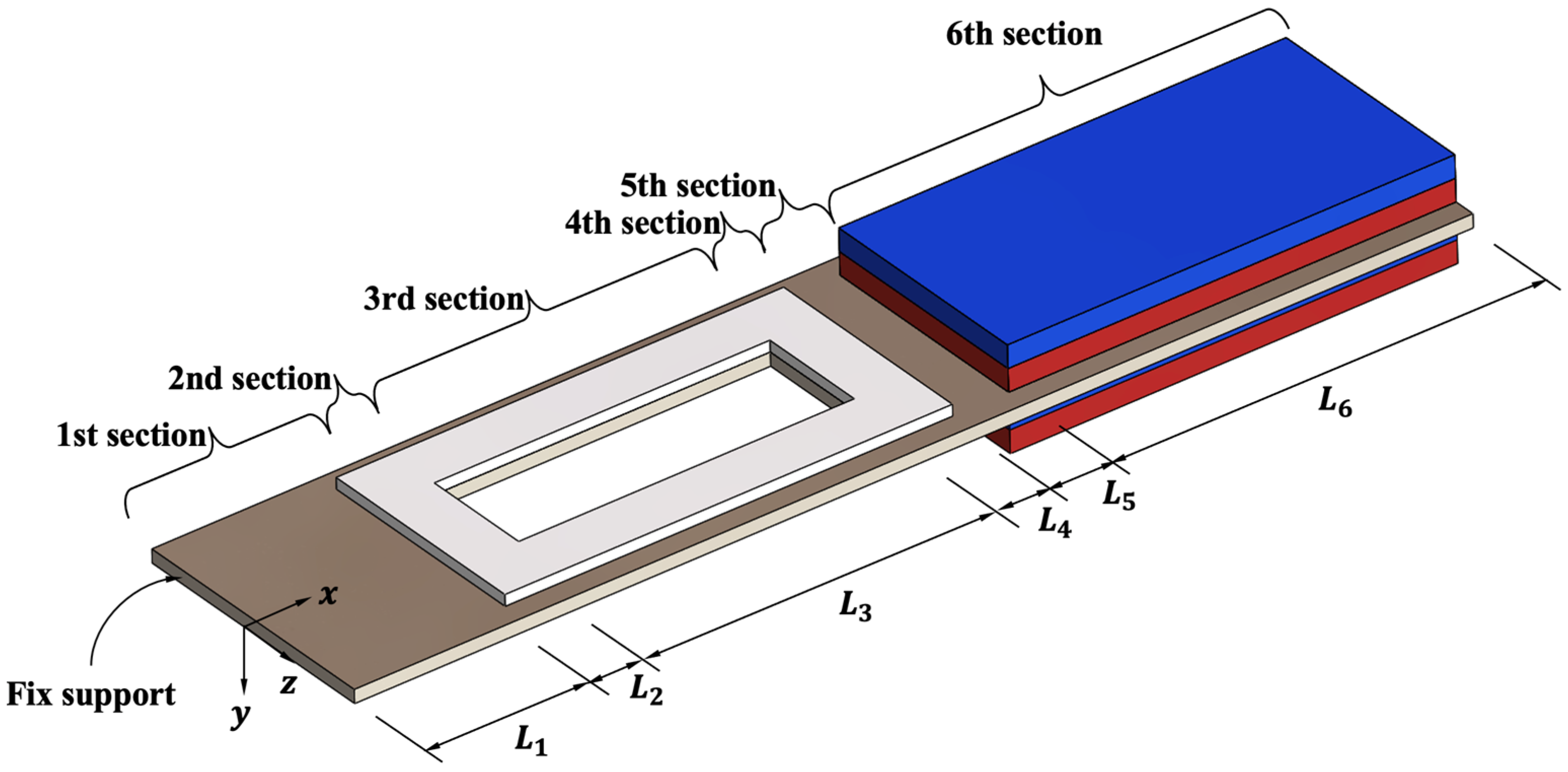
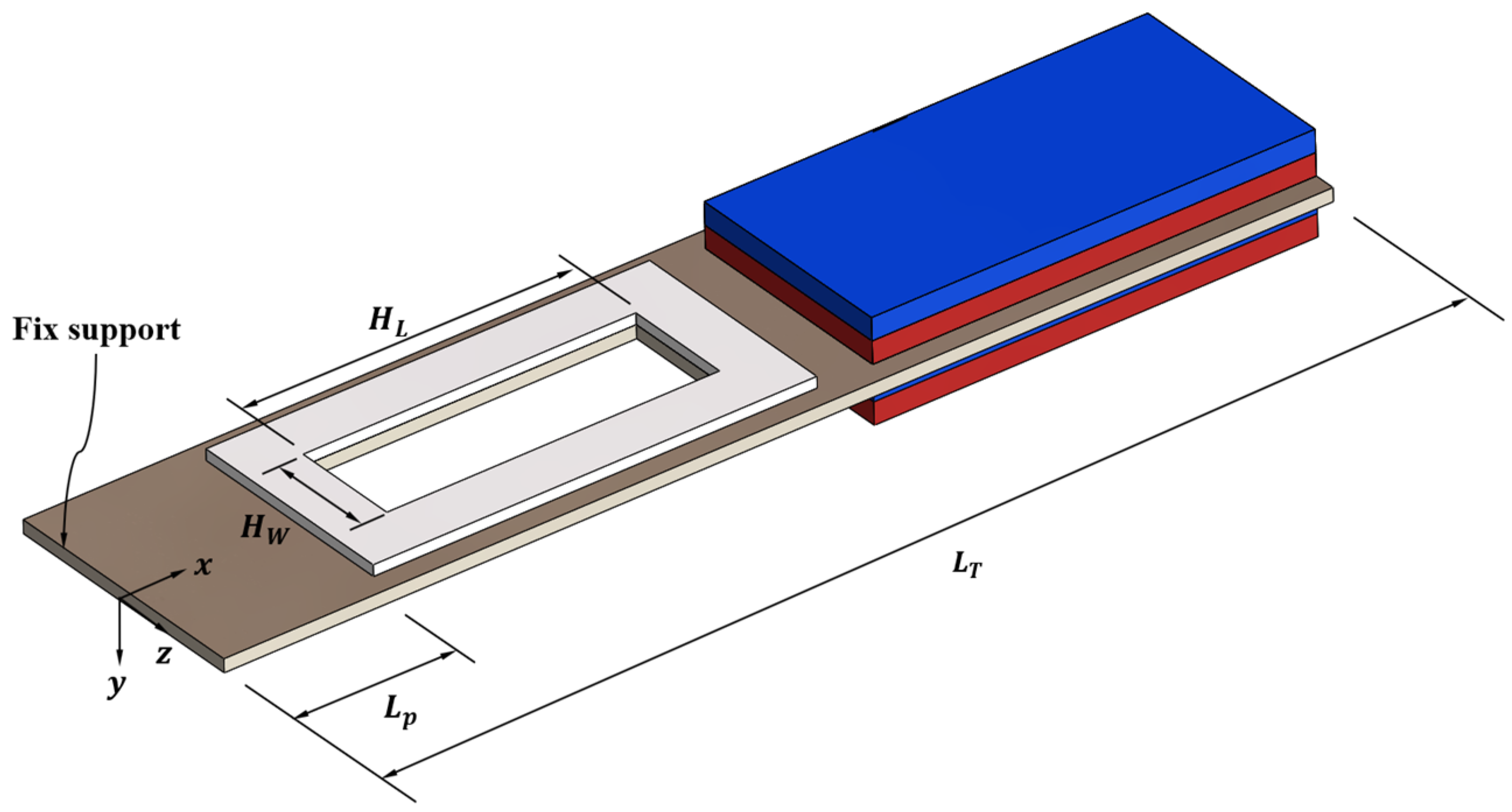
Mechanical vibrations in induction electric motors can arise from rotational imbalances [35,36], misalignments [37,38], bearing issues [39], and electromagnetic sources [40,41,42,43]. These vibrations occur at specific frequencies determined by the operational characteristics of the motor. Figure 1 illustrates the main electromechanical components of a four-pole induction electric motor (7.5 kW) operating at 60 Hz and 1800 rpm. This type of motor is widely used in industrial applications such as pumps, compressors, and conveyors, making it a relevant case for evaluating a pVEH’s performance in real-life scenarios. The fundamental vibration frequencies of an induction electric motor are as follows: the supply frequency (fs = 60 Hz) is associated with electromagnetic forces, while the rotational frequency (fR = 30 Hz) is related to mechanical imbalances. Additionally, the second harmonic (2·fs = 120 Hz) often indicates structural imperfections or misalignment.
Figure 2 shows the vibration spectrum of an induction motor, representing the acceleration as a function of the frequency. The peaks at 30 and 60 Hz indicate energy-rich frequency regions, which are suitable for harvesting using a pVEH. These vibrations can be described by their acceleration (a):
a = ( a c c ) g   sin ω t ,
where acc is the acceleration coefficient (ranging from 0.1 to 10), g is the gravitational acceleration, and ω is the angular frequency equivalent to 2πfr.
The corresponding force per unit volume (FV) applied to the piezoelectric device is expressed as
F V = ( a c c ) ρ g   sin ω t ,
where ρ is the density of the material. This inertial force induces mechanical deformation in the piezoelectric layer of the pVEH, enabling energy conversion through the piezoelectric effect.
The proposed pVEH is designed to convert mechanical vibrations into electrical energy by using a multilayered piezoelectric cantilever beam. Figure 3a depicts the energy harvester in its undeformed state, where input vibrations generate periodic accelerations in the beam. When excited at a specific frequency, the piezoelectric layer undergoes mechanical strain (S1) due to the inertia-induced bending of the structure. Figure 3b depicts the deformed state of the pVEH, where the applied stress polarizes the piezoelectric layer, leading to the generation of an open-circuit voltage (VOC). This stress is associated with a force per unit volume (FV) that depends on the input acceleration amplitude and the structural characteristics of the energy harvester. The generated open-circuit voltage (VOC) can be expressed as a function of the material properties of the pVEH [44,45,46]:
V O C = d 31 · S 1 · h ε r · ε 0
where d31 is the piezoelectric strain coefficient that defines the electromechanical coupling of the piezoelectric material, S1 represents the mechanical strain induced by vibrations, h is the thickness of the piezoelectric layer (m), εr is the relative permittivity of the piezoelectric material, and ε0 is the permittivity of the vacuum (8.85 × 10⁻¹² F/m).
Figure 1. Main electromechanical components of a 4-pole induction electric motor (7.5 kW) operating at 60 Hz and 1800 RPM, including the stator, rotor, bearings, shaft, and frame. These components have a key role in the generation of mechanical vibrations that can be leveraged by pVEHs.
Technologies 13 00194 g001
Figure 2. Vibration spectrum of an induction electric motor with dominant peak values at 30 Hz, 60 Hz (supply frequency), and 120 Hz, corresponding to typical sources of mechanical vibrations. The severity of these vibrations is evaluated based on the peak-to-peak acceleration levels (g) and categorized according to the machine’s operational conditions, providing information on potential mechanical failures and their impact on the system performance (ISO 10816-1:1995) [47]. The color-coded severity matrix represents the machine condition as follows: dark green indicates “Good” (no risk of failure), light green indicates “Satisfactory” (normal operation with low risk), yellow indicates “Unsatisfactory” (incipient fault or moderate risk), and red indicates “Unacceptable (Danger)” (high risk of severe failure requiring immediate intervention).
Technologies 13 00194 g002
Figure 3. Operating principle of the pVEH: (a) Initial configuration of the multilayer piezoelectric cantilever beam of the pVEH subjected to input vibration accelerations with peak-to-peak amplitudes. The beam remains non-deformed, featuring a piezoelectric layer attached to a substrate layer and a permanent magnet at the free end. (b) Deformed state of the cantilever beam of the pVEH due to vibrations along the y-axis in its base structure. The displacement (δy) of the pVEH induces mechanical stress in the polarized piezoelectric layer, leading to the generation of an open-circuit voltage (VOC). The color gradient on the piezoelectric layer qualitatively illustrates the stress distribution along the beam, with blue indicating regions of low stress and red representing areas of high stress.
Technologies 13 00194 g003
In the d 31 mode, the applied mechanical strain ( S 1 ) is oriented along the 1-axis, perpendicular to the direction of polarization, while the electrical charge is collected in the same plane as where the strain is applied. The maximum output power (Pmax) obtained using the piezoelectric material can be expressed as [48]
P m a x = R o p t ω d 31 S 1 A 2 1 + R o p t ω A h ε 33 T d 31 2 s 11 E 2
where ε 33 T is the relative permittivity of the material along the polarization direction, influencing the stored electric charge, s 11 E is the compliance coefficient in the 1-direction, representing the material’s mechanical flexibility under the applied stress, and Ropt is the external load resistance that affects the energy transfer efficiency. This Ropt can be calculated by [49]
R o p t = 1 ω A h · ε 33 T d 31 2 s 11 E
The performance of a resonant structure is strongly influenced by its quality factor (Q), which represents the ratio between the stored and dissipated energy per cycle of oscillation. A high quality factor implies low energy dissipation, improving the performance of resonators. On the other hand, a low quality factor causes higher energy losses, limiting the resonator’s displacement and sensitivity. In practical applications, damping due to air resistance has a significant role in reducing the quality factor. The Q is inversely proportional to the damping ratio (ζ) [48]. The Blom model [50] is used to determine the effect of air damping on the quality factor of the resonator, incorporating parameters such as the air viscosity, density, material properties, and cantilever geometry. This Blom model can be used to calculate the quality factor (Qa) of a resonator affected by air damping:
Q a = f r ρ b h L e 3 μ R 1 + R / β
where fr is the resonant frequency, ρ is the density of the material, b and h are the width and thickness of the structure, Le is the effective length, μ is the air viscosity, and R and β are dimensionless parameters given by
β = μ π ρ a f r
R = b L e π
These parameters incorporate the effects of the air density and structural dimensions.

2.2. Design

The design of the piezoelectric energy harvester was based on a cantilever structure with a coupled piezoelectric layer and permanent magnets attached to its free end as a tip mass. Figure 4 depicts the main components of the pVEH. A central rectangular slot was introduced at the root of the cantilever beam, extending through both the substrate and piezoelectric layers. This feature was strategically incorporated to reduce the overall mechanical stiffness and first bending resonant frequency of the pVEH. Although the slot introduces local stress concentrations near its corners, this slot also contributes to a more distributed stress pattern across the piezoelectric patch. This redistribution enhances the overall activation of the material and improves the energy conversion efficiency.
The cantilever was designed using 304 stainless steel, while the piezoelectric layer was composed of PZT-5H, and the tip mass was formed of two permanent magnets made of neodymium N35. Neodymium magnets were selected as tip masses due to their high mass density and compact size, which could effectively increase the cantilever’s inertia without increasing its dimensions. These magnets added mass to the pVEH and their small size and location away from the magnetic core of the electric motor minimized any potential interference. Although different electric motor configurations may lead to variations in the vibration spectrum, the proposed parametric modeling strategy enables the adaptation of a pVEH’s geometry to match the dominant excitation frequencies of industrial electric motors. Thus, this parametric modeling approach can be employed to predict the optimal dimensions of the resonant structures of pVEHs that will improve their output performance for each specific application in industrial environments.
A comprehensive description of these material properties is presented in Table 1. The piezoelectric coefficient matrix (d), compliance coefficient matrix (s), and dielectric coefficient matrix (εr) for the PZT-5H material are presented in Equations (9)–(11), respectively.
d = 0 0 0 0 7.41 0 0 0 0 7.41 0 0 2.74 2.74 5.93 0 0 0 × 10 10   C / N
s = 16.5 4.78 8.45 0 0 0 4.78 16.5 8.45 0 0 0 8.45 8.45 20.7 0 0 0 0 0 0 43.5 0 0 0 0 0 0 43.5 0 0 0 0 0 0 42.6 × 10 12   Pa 1
ε r = 3130 0 0 0 3130 0 0 0 3400

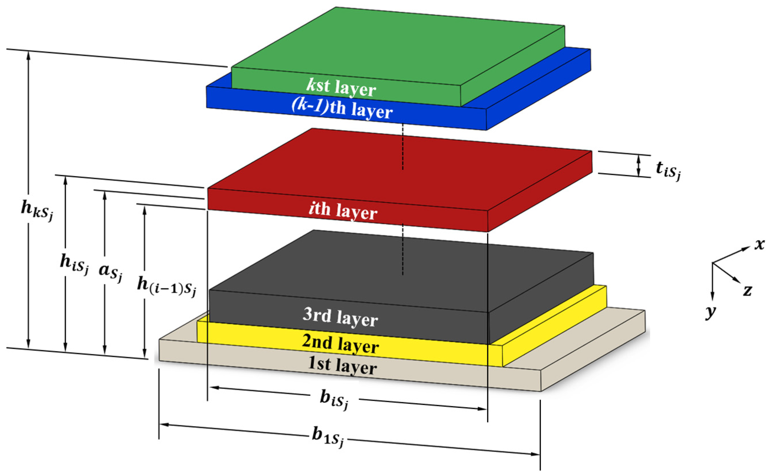
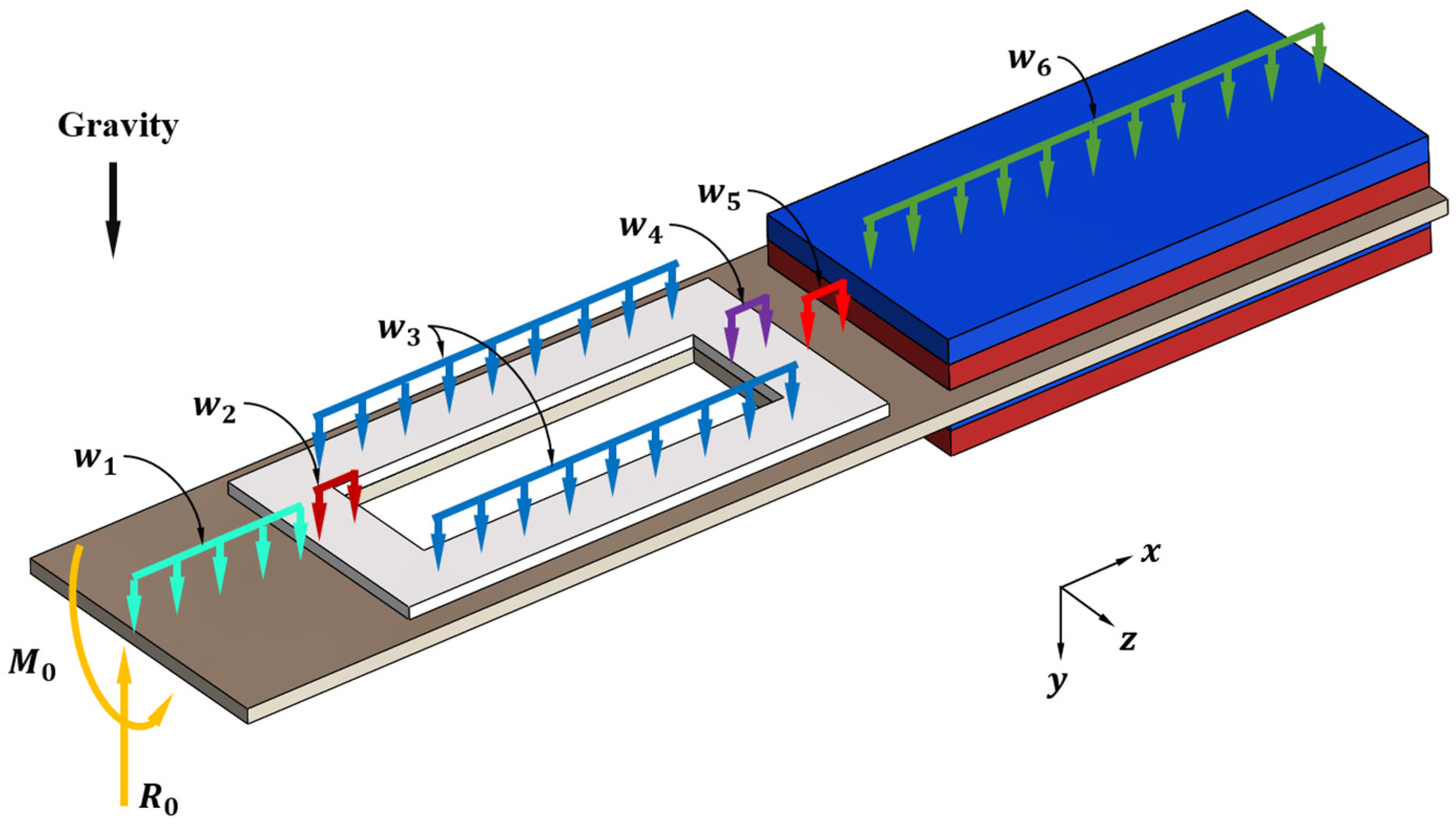
2.3. The Mathematical Modeling of a Multilayered Resonant Cantilever

To predict the first bending resonant frequency of the pVEH, the Rayleigh method was used, incorporating the Euler–Bernoulli beam theory [54]. The Rayleigh method can be used to estimate the natural frequencies of resonators by considering the relationship between their maximum potential energies (Pm) and maximum kinetic energies (Km). By assuming that the structure undergoes small deflections, we could approximate its dynamic behavior through an energy-based formulation. The potential energy was given by
P m = 1 2 0 L E I ( x ) 2 y x 2 2 d x
where EI(x) is the bending rigidity as a function of the position along the beam, and y(x) is the bending displacement at a specific point along the x-axis of the cantilever. The kinetic energy was expressed as
K m = 2 π f 2 2 0 L ρ A x y 2 ( x ) d x
where A(x) is the cross-sectional area, and ρ is the material density. Based on the energy conservation of the maximum potential and kinetic energy (Pm = Km), the fundamental bending resonant frequency was obtained as
f r = 1 2 π 0 L E I ( x ) 2 y ( x ) x 2 2 d x 0 L ρ A x y 2 ( x ) d x
The Euler–Bernoulli beam theory is particularly suited for slender structures with small transverse displacements. This theory assumes that plane sections remain plain and perpendicular to the neutral axis after deformation, which simplifies the calculation of the bending stiffness. However, for multilayered structures, special attention must be given to variations in material properties across different sections, requiring adjustments to the classical beam formulation.
In the mathematical model, the geometric dimensions of the structure of the pVEH were considered as parametric variables. Figure 5 illustrates the geometric parameters of the pVEH resonator, considering six different geometric sections. The first section 1 was composed of a single layer of stainless steel. The second, third and fourth sections contained two layers, combining stainless steel and PZT-5H layers. The fifth section had a single layer of stainless steel. Finally, the sixth section incorporated a multilayer configuration, involving a stainless steel substrate sandwiched between two neodymium N35 magnet layers. The consideration of copper electrodes was neglected in the proposed model due to their negligible thickness (~100 nm) relative to that of the structural layers.
Given the multilayered composition of the resonator and the varying mechanical properties of each section, the elastic centroid (aSj) needed to be determined for each segment. This centroid defined the neutral axis of the resonator, and its value was based on the vertical position of each layer relative to the bottom surface of the first layer in that section (hiSj). Figure 6 illustrates this, emphasizing the contribution of each material layer to the elastic centroid [55]. The elastic centroid could be determined using Equation (15), which considers the elastic modulus (EiSj), width (biSj), and thickness (tiSj) of the ith layer within the jth section. Once the elastic centroid was determined, the equivalent bending stiffness (EI)Sj was calculated, as shown in Equation (16). In multilayer sections, the bending stiffness was computed by summing the contributions of the individual layers, considering their relative position with respect to the elastic centroid. Figure 7 depicts the uniformly distributed loads (wSj) acting on the jth cross-section, along with the bending moments (M0) and reaction forces (R0) at the fixed support of the equivalent resonator.
a S j = E S S j E A S j = A S j E S j y S j x d y d x A S j E S j d y d x = 1 2 i = 1 q E i S j b i S j t i S j h i S j + h i 1 S j i = 1 q E i S j b i S j t i S j
where h(i−1)Sj is the distance between the bottom surface of the first layer and the top surface of the (i−1)th layer situated in the jth section.
E I S j = i q E i I j S j = A S j E S j y S j x d y = 1 2 i = 1 q E i S j b i S j h i S j a S j 3 h i 1 S j a S j 3
To obtain the maximum kinetic energy (Km) and potential energy (Pm) of the equivalent resonator, we used the following expressions:
P m = 1 2 E I S 1 0 L 1 2 y S 1 ( x ) x 2 2 d x + E I S 2 L 1 L 12 2 y S 2 ( x ) x 2 2 d x + E I S 3 L 12 L 123 2 y S 3 ( x ) x 2 2 d x + E I S 4 L 123 L 1234 2 y S 4 ( x ) x 2 2 d x + E I S 5 L 1234 L 12345 2 y S 5 ( x ) x 2 2 d x + E I S 6 L 12345 L 123456 2 y S 6 ( x ) x 2 2 d x
K m ω 2 = 1 2 i = 1 q ρ i S 1 b i S 1 t i S 1 0 L 1 y S 1 ( x ) 2 d x + i = 1 q ρ i S 2 b i S 2 t i S 2 L 1 L 12 y S 2 ( x ) 2 d x + i = 1 q ρ i S 3 b i S 3 t i S 3 L 12 L 123 y S 3 ( x ) 2 d x + i = 1 q ρ i S 4 b i S 4 t i S 4 L 123 L 1234 y S 4 ( x ) 2 d x + i = 1 q ρ i S 5 b i S 5 t i S 5 L 1234 L 12345 y S 5 ( x ) 2 d x + i = 1 q ρ i S 6 b i S 6 t i S 6 L 12345 L 123456 y S 6 ( x ) 2 d x
where L12 = L1 + L2, L123 = L1 + L2 + L3, L1234 = L1 + L2 + L3 + L4, L12345 = L1 + L2 + L3 + L4 + L5, L123456 = L1 + L2 + L3 + L4 + L5 + L6, and ω = 2πf.
Based on the Rayleigh method, we estimated the first bending resonant frequency of the equivalent resonator as
f r = 1 2 π P m K m / ω 2
The Euler–Bernoulli beam theory was used to determine the deflections of the resonator. Thus, the deflections in the six sections of the equivalent resonator could be obtained by
E I S 1 2 y S 1 ( x ) x 2 = M S 1 x                   0 < x < L 1 E I S 2 2 y S 2 ( x ) x 2 = M S 2 x                   L 1 < x < L 12 E I S 3 2 y S 3 ( x ) x 2 = M S 3 x                   L 12 < x < L 123 E I S 4 2 y S 4 ( x ) x 2 = M S 4 x                   L 123 < x < L 1234 E I S 5 2 y S 5 ( x ) x 2 = M S 5 x                   L 1234 < x < L 12345 E I S 6 2 y S 6 ( x ) x 2 = M S 6 x                   L 12345 < x < L 123456
where MSj is the bending moment of the jth section of the equivalent resonator, which could be determined using the internal bending moment in each section and applying the static equilibrium equation as follows.
For   0 < x < L 1 , M S 1 x = M 0 R 0 x + w 1 2 x 2 For   L 1 < x < L 12 , M S 2 x = M 0 R 0 x + w 2 2 x L 1 2 + w 1 L 1 x L 1 2 For   L 12 < x < L 123 , M S 3 x = M 0 R 0 x + w 3 2 x L 12 2 + w 2 L 2 x L 1 L 2 2 + w 1 L 1 x L 1 2 For   L 123 < x < L 1234 M S 4 x = M 0 R 0 x + w 4 2 x L 123 2 + w 3 L 3 x L 12 L 3 2 + w 2 L 2 x L 1 L 2 2 + w 1 L 1 x L 1 2 For   L 1234 < x < L 12345 M S 5 x = M 0 R 0 x + w 5 2 x L 1234 2 + w 4 L 4 x L 123 L 4 2 + w 3 L 3 x L 12 L 3 2 + w 2 L 2 x L 1 L 2 2 + w 1 L 1 x L 1 2 For   L 12345 < x < L 123456 , M S 6 x = M 0 R 0 x + w 6 2 x L 12345 2 + w 5 L 5 x L 1234 L 5 2 + w 4 L 4 x L 123 L 4 2 + w 3 L 3 x L 12 L 3 2 + w 2 L 2 x L 1 L 2 2 + w 1 L 1 x L 1 2
where
R 0 = w S 1 L 1 + w S 2 L 2 + w S 3 L 3 + w S 4 L 4 + w S 5 L 5 + w S 6 L 6
M 0 = w S 1 L 1 L 1 2 + w S 2 L 2 L 1 + L 2 2 + w S 3 L 3 L 12 + L 3 2 + w S 4 L 4 L 123 + L 4 2 + w S 5 L 5 L 1234 + L 5 2 + w S 6 L 6 L 12345 + L 6 2 +
To obtain the static deflections ySj(x) in the six sections of the equivalent resonator, the equations of the bending moments were substituted into Equation (20).
For   0 < x < L 1 y S 1 x = M 0 x 2 2 R 0 x 3 6 + w 1 x 4 24 + C 1 x + C 2 For   L 1 < x < L 12 y S 2 x = 1 2 M 0 x 2 1 6 R 0 x 3 + 1 24 w 2 x L 1 4 + 1 6 w 1 L 1 x L 1 2 3 + C 3 x + C 4 For   L 12 < x < L 123 y S 3 x = 1 2 M 0 x 2 1 6 R 0 x 3 + 1 24 w 3 x L 12 4 + 1 6 w 2 L 2 x L 1 L 2 2 3 + 1 6 w 1 L 1 x L 1 2 3 + C 5 x + C 6 For   L 123 < x < L 1234 y S 4 x = 1 2 M 0 x 2 1 6 R 0 x 3 + 1 24 w 4 x L 123 4 + 1 6 w 3 L 3 x L 12 L 3 2 3 + 1 6 w 2 L 2 x L 1 L 2 2 3 + 1 6 w 1 L 1 x L 1 2 3 + C 7 x + C 8 For   L 1234 < x < L 12345 y S 5 x = 1 2 M 0 x 2 1 6 R 0 x 3 + 1 24 w 5 x L 1234 4 + 1 6 w 4 L 4 x L 123 L 4 2 3 + 1 6 w 3 L 3 x L 12 L 3 2 3 + 1 6 w 2 L 2 x L 1 L 2 2 3 + 1 6 w 1 L 1 x L 1 2 3 + C 9 x + C 10 For   L 12345 < x < L 123456 y S 6 x = 1 2 M 0 x 2 1 6 R 0 x 3 + 1 24 w 6 x L 12345 4 + 1 6 w 5 L 5 x L 1234 L 5 2 3 + 1 6 w 4 L 4 x L 123 L 4 2 3 + 1 6 w 3 L 3 x L 12 L 3 2 3 + 1 6 w 2 L 2 x L 1 L 2 2 3 + 1 6 w 1 L 1 x L 1 2 3 + C 11 x + C 12
To determine the magnitudes of the integration constants, the deflection ySj(x) of our resonator needed to satisfy the following boundary conditions:
y S 1 0 = 0                                                   y S 1 ( 0 ) x = 0 y S 1 L 1 = y S 2 L 1                                                 y S 1 ( L 1 ) x = y S 2 ( L 1 ) x   y S 2 L 12 = y S 3 L 12                                     y S 2 ( L 12 ) x = y S 3 ( L 12 ) x y S 3 L 123 = y S 4 L 123                                 y S 3 ( L 123 ) x = y S 4 ( L 123 ) x   y S 4 L 1234 = y S 5 L 1234                                 y S 4 ( L 1234 ) x = y S 5 ( L 1234 ) x   y S 5 L 12345 = y S 6 L 12345                         y S 5 ( L 12345 ) x = y S 6 ( L 12345 ) x     y S 6 L 123456 = y S 7 L 123456                   y S 6 ( L 123456 ) x = y S 7 ( L 123456 ) x  
Finally, the values of the constants were substituted into Equation (24), allowing us to predict the first bending resonant frequency of the equivalent resonator of the pVEH by incorporating Equation (24) into Equations (17)–(19).
By considering small deflections of the structure at resonance, we estimated the dynamic deflections (yd) of the piezoelectric device, multiplying its static deflections (ySj) by the quality factor due to the air damping of the resonator [56]:
y d = y S j Q a
Table 2 summarizes the geometric parameters of the equivalent resonator layers of the pVEH used in the proposed mathematical model. In addition, Table 3 shows the values for the effective stiffness, weight per unit length, reaction load ( R 0 ), and bending moment ( M 0 ) of this equivalent resonator. Based on the values in Table 2 and Table 3, the first bending resonant frequency of the equivalent resonator of the pVEH was 35.94 Hz.

3. Parametric Design

Figure 8 shows the parametric design of the pVEH resonator, which was performed to select its optimal dimensions. The substrate beam length (LT) varied from 50 mm to 90 mm in 10 mm increments. The initial position of the piezoelectric layer (LP) ranged from 1 mm to 9 mm, increasing in 3 mm steps. A centrally located rectangular hollow section within the piezoelectric layer was defined by a hollow length (HL) varying from 5 mm to 15 mm in 5 mm steps and a hollow width (HW) ranging from 1 mm to 5 mm in 2 mm increments. These parameters were carefully selected during the design stage to enhance resonance tuning and increase the output performance of the energy harvester.
First, numerical simulations were conducted for various substrate lengths (LT) with values of 50, 60, 70, 80, and 90 mm, piezoelectric patch positions (LP) 1, 3, 5, 7, and 9 mm along the cantilever beam, rectangular hole lengths (HL) of 5, 10, and 15 mm, and rectangular hole widths (HW) of 1, 3, and 5 mm, resulting in a total of 225 combinations. The boundary conditions were set by fixing one end of the device, allowing for free vibration at the other. The computational mesh consisted of hexahedral elements with a base size of 1 mm, refined in high-deformation regions to improve the accuracy of the results (0.5 mm). The external excitation was fixed at 0.1 g.
The performance of the pVEH was evaluated based on the resonance frequency that maximized both the open-circuit voltage (VOC) and the principal stress on the substrate material. The analysis focused on the influence of the substrate length and piezoelectric patch position, keeping the hole dimensions constant. The results, presented in Figure 9, provide a visual representation of how these parameters affected the pVEH’s performance. The results indicate that the resonance frequency was significantly affected by changes in the substrate length, while its dependence on the position of the piezoelectric patch was less pronounced. When the piezoelectric patch was positioned at 1 mm along the cantilever beam and the total cantilever length was 50 mm, the resonance frequency was approximately 96.5 Hz. However, when the substrate length increased to 90 mm, the resonance frequency decreased to values close to 30 Hz. Although the position of the piezoelectric patch had a limited effect on the resonance frequency, its impact was more noticeable with shorter substrates.
Additionally, a quasi-linear trend was observed between the resonance frequency and the piezoelectric patch position as the substrate length increased, as shown in Figure 9. The resonance frequency of the pVEH tended to decrease as the LP moved farther from the clamped end and as the substrate length increased from 50 mm to 80 mm. However, at LT = 90 mm, the resonance frequency of the pVEH tended to increase as the LP moved away from the clamped end. For vibrational energy harvesting in induction electric motors operating at 30 Hz, the most efficient geometric configurations were identified. For a 30 Hz operating frequency, the most suitable configuration of the PVEH resonator was LT = 90 mm, with the piezoelectric patch position ranging from 1 to 9 mm along the cantilever beam, yielding a resonance frequency of between 30 Hz and 36 Hz when HL = 5 mm and HW = 1 mm.
A detailed analysis was conducted for the configuration with LT = 90 mm. In this evaluation, the LP varied from 1 mm to 9 mm along the cantilever beam, the HL from 5 mm to 15 mm in 5 mm increments, and the HW from 1 mm to 5 mm in 2 mm steps. The parametric analysis focused on the influence of the hole geometry on the resonance frequency, aiming to identify configurations operating close to 30 Hz. The results shown in Figure 10a–e correspond to the configuration in which the piezoelectric patch was positioned from 1 mm to 9 mm along the cantilever beam. Figure 10a, corresponding to LP = 1 mm, shows the relationship between the resonance frequency and hole dimensions. The hole size significantly influenced the resonance frequency of the pVEH resonator. Specifically, as the HL and HW increased, the frequency of the resonator tended to decrease in a nonlinear fashion.
In Figure 10a, two points of interest can be identified with a resonance frequency close to 30 Hz. These points are found for the configurations where HL = 5 mm and HW = 5 mm and HL = 15 mm and HW = 3 mm. In Figure 10b, when the patch position is LP = 3 mm, a point of interest is found with a configuration where HL = 10 mm and HW = 5 mm. In Figure 10c, with LP = 5 mm, another point of interest is identified with a resonance frequency close to 30 Hz for the configuration where HL = 15 mm and HW = 5 mm. On the other hand, in Figure 10d,e, corresponding to LP = 7 mm and LP = 9 mm, the resonance frequencies do not match 30 Hz, indicating that these configurations did not meet the desired frequency criterion.
Table 4 summarizes the best results for the output voltage and maximum von Mises stress of the pVEH when the piezoelectric patch was positioned at LP = 1 mm, 3 mm, and 5 mm along the cantilever beam, corresponding to a resonance frequency of 30 Hz. The highest output voltage and maximum von Mises stress values of the device were 132.6 V and 296.3 MPa, respectively, which were obtained when HL = 15 mm and HW = 3 mm. Furthermore, the energy efficiency factor (Ef = Voltage/Stress) of the piezoelectric device relating the generated voltage to the induced mechanical stress was 0.45 V/MPa. Another notable configuration was that where HL = 15 mm and HW = 5 mm, where the voltage and maximum principal stress were 87.8 V and 230.3 MPa, respectively. The corresponding efficiency factor in this case was 0.38 V/MPa. These results suggest that the optimal configuration was achieved at LP = 1 mm, with HL = 15 mm and HW = 3 mm, as it provided the best trade-off between voltage generation and mechanical stress.

4. Results and Discussion

Based on the parametric analysis of the pVEH, its electromechanical performance was evaluated through finite element method (FEM) simulations using COMSOL Multiphysics. In this analysis, a refined mesh of the simulation model was used. A hexahedral mesh with a 0.5 mm element size was employed, with further refinement to 0.25 mm in the piezoelectric region and around the central slot. As an initial step, a modal analysis was carried out to identify the natural frequencies of the first four vibration modes. The first mode, characterized by a bending deformation, occurred at ≈29.2 Hz (see Figure 11a). The second and third modes occurred close to 308.3 Hz and 519.9 Hz, respectively, as shown in Figure 11b,c. The fourth mode, with a resonant frequency of around 557.5 Hz, exhibited lateral displacement behavior (see Figure 11d).
Next, a multiphysics coupled analysis incorporating the piezoelectric effect was conducted. A frequency domain analysis was performed, spanning from 29 Hz to 31 Hz in 0.01 Hz increments. The stationary solver of COMSOL was configured to be nonlinear, with a relative tolerance of 0.001. In the solid mechanics module, an isotropic structural loss factor (1/Qa) of 0.0003 was applied to a linear elastic material, where Qa was calculated using Equation (6). A body load, defined by Equation (2), was introduced with an acceleration of 0.035 acc. In the electrostatics and electrical circuit modules, terminal and ground boundaries were configured to establish a closed electrical circuit with a variable external resistance. To determine the optimal load conditions, a resistance sweep was performed from 101 to 1010 Ω, using logarithmic step increments of 100.1 Ω.
Figure 12 depicts the results for the harmonic and piezoelectric simulation models. The resonance frequency of the pVEH was 30.07 Hz, with a corresponding output voltage of 127.5 V, as shown in Figure 12a. This resonant frequency exhibited a relative difference of −15.3% compared to that of the analytical model. In addition, the relationship between the output voltage, real average output power, and external resistance was analyzed. As the resistance increased, the output voltage initially rose before stabilizing, while the output power followed a characteristic curve, increasing to a maximum and then decreasing. According to the maximum power transfer theorem, the maximum output power is achieved when the external resistance matches the internal resistance of the piezoelectric cantilever, which was found to be 6309.6 kΩ. The output power of the pVEH was 3.26 mW, as shown in Figure 12b. The results for the output voltage of the pVEH under acceleration levels from 0 to 0.1 g, increasing in 0.01 g increments, demonstrated a linear correlation between the peak output voltage and acceleration, described by the regression equation V = 1326.1 acc. Similarly, the von Mises stress response in the stainless steel substrate under varying acceleration levels (0–0.1 g) also registered a linear trend, described by the equation σS = 2962.9 acc. At the interface between the substrate and the piezoelectric patch, the stress also exhibited linear behavior, given by σI = 1724.3 acc. Finally, for the PZT-5H piezoelectric patch, the observed stress response was also linear, with the regression equation being σP = 1412.8 acc. The linear behavior of both the output voltage and von Mises stress of the pVEH with respect to the acceleration is suitable to predict its electromechanical performance in different applications of industrial electric motors. This outcome is particularly important for energy harvesting applications, as it enables the accurate estimation of both the generated voltage and the resulting structural stresses based on the input acceleration. This linear behavior facilitates the optimization of the pVEH design, which can maximize the energy conversion efficiency while preserving the structural integrity of the device.
Finally, a mechanical analysis was conducted to evaluate the stress distribution in both the piezoelectric layer and the main substrate, identifying the regions with the highest stress concentration. According to the results shown in Figure 12d, an acceleration coefficient of 0.072 corresponded to a yield strength of 215 MPa for 304 stainless steel. Similarly, a bending strength of 123.2 MPA for the PZT-5H piezoelectric patch was reached at an acceleration coefficient of 0.087 [1]. Since the lower of the two defines the safe operating limit, the pVEH must be operated within an acceleration range of 0 to 0.07 g to maintain structural integrity. This constraint ensures resonance-based operation while keeping all materials within their elastic deformation range. The highest stress concentrations were located at the vertices of the central rectangular slot near the clamped end of the cantilever, as illustrated in Figure 13a. The stress progressively decreased along the length of the beam toward the free end. In parallel, the deflection analysis revealed that the maximum displacement occurred at the free end, reaching 3.8 mm when the device operated at resonance, as shown in Figure 13b.
Figure 14 compares the maximum displacements of the pVEH at resonance obtained from both the analytical model and FEM simulations. The analytical model consistently predicted higher displacement values than those obtained from the numerical model. However, both approaches exhibited similar increasing trends as the length of the pVEH resonator increased. Further investigation is needed to better account for factors such as the quality factor and residual stress in the electromechanical models, as these may have contributed to the observed discrepancies and influenced the dynamic response of the system.
Our electromechanical model of pVEHs can predict their deflections and output voltages, caused by low-frequency vibrations from industrial induction motors. The proposed modeling approach incorporates (i) a central rectangular slot in both the substrate and piezoelectric layers to adjust the structural flexibility and fine-tune the resonant frequency; (ii) a parametric study of the piezoelectric patch position along the cantilever beam; and (iii) an evaluation of the electromechanical response under varying acceleration levels and load resistances. This modeling approach can be used to determine the optimal dimensions of the proposed pVEH for specific applications in different industrial electric motors.
Several factors must be considered for the real-world implementation of our electromechanical modeling and simulations of pVEHs. These factors are important to achieving the feasibility and long-term potential of the proposed pVEH. In practical applications, the vibration spectrum of induction electric motors is strongly influenced by factors such as the loading conditions, installation geometry, and mechanical wear. These factors may shift the dominant excitation frequency, requiring the energy harvester to be either specifically tuned or adaptable to a wider frequency range. Moreover, our parametric modeling methodology allows for the adjustment of geometric and electrical parameters to suit specific operating contexts. Mechanical integration is another key factor for the real-world application of pVEHs. These pVEHs must be installed on the motor housing without interfering with its operation, safety, or maintenance procedures. Space constraints, the mounting orientation, and vibration transmission paths must be considered. Figure 15 depicts the complete piezoelectric energy harvesting system installed on an induction motor. In this design, the mechanical vibrations generated by the motor serve as the excitation source. The pVEH housing refers to the structural enclosure that supports and secures the energy harvester to ensure mechanical contact with the motor casing, ensuring effective vibration transfer. Thus, the generated alternating current flows through an AC output cable that connects to the Power Management Unit (PMU) casing. This PMU includes the electronic components for rectifying, regulating, and storing the energy harvested by pVEHs under the different vibration magnitudes of industrial electric motors.
From an electrical integration standpoint, the simulated optimal load resistance for the maximum power transfer was found to be approximately 6309.6 kΩ. This load resistance maximizes the output power of the pVEH; however, it presents challenges in terms of impedance matching and interfacing with electronic circuits. For instance, the high impedance and high output voltage of a pVEH require signal conditioning stages that minimize the voltage drop and avoid excessive current consumption. The architecture begins with the equivalent electrical model of the piezoelectric device, consisting of a current source (Ieq), parallel capacitance (Cp), and internal resistance (Rp). Immediately downstream, an RC low-pass filter composed of (Rf) and (Cf) is introduced to suppress high-frequency noise and limit the current fed into the buffer circuit. This filter is crucial for stabilizing the signal before voltage sensing and rectification. A high-input impedance buffer circuit, implemented using an OPA140 operational amplifier, is after the filter. This stage serves to electrically decouple the high-impedance source from the downstream circuitry, preserving the voltage level and avoiding loading effects. The buffered AC signal is then fed into a high-voltage rectifier using fast-recovery diodes (BYV26E), selected for their high reverse voltage tolerance and low leakage current. The rectified voltage is temporarily stored in a capacitor (C0) that acts as an intermediate energy reservoir and smooths the voltage fluctuations caused by the intermittent nature of mechanical vibrations. Subsequently, a DC-DC boost converter with integrated maximum power point tracking (MPPT) functionality—realized through the use of a BQ25570 power management IC—is used to elevate and regulate the voltage. This module ensures that energy is extracted from the energy harvester under varying load conditions. The regulated output voltage is stored in a secondary capacitor (C1) that functions as the final energy buffer before supplying the monitoring node. The monitoring node may consist of a microcontroller, sensor, or wireless transmitter depending on the application. This power conditioning circuit enables autonomous operation under low-frequency excitation (~30.25 Hz) and low mechanical acceleration (0.1–1 g), enabling the feasibility of the proposed piezoelectric device for potential application as a clean electrical energy source to power industrial IoT sensors. A block diagram summarizing this architecture is presented in Figure 16.

5. Conclusions

The electromechanical modeling and parametric analysis of a pVEH for induction electric motors operating at 30 Hz were performed. This piezoelectric device was composed of a cantilever beam as the substrate, a piezoelectric layer with a rectangular hole, and two magnet layers. We assessed the substrate lengths, piezoelectric patch positions, and hole dimensions of the pVEH, considering their impact on its resonance frequency, output voltage, and structural integrity. The Rayleigh method, incorporating the Euler–Bernoulli beam theory, was used to predict the first bending resonant frequency and static deflection of the piezoelectric device. Based on FEM simulations of this device, the substrate length strongly affected the resonance frequency of the device, while the piezoelectric patch position had a minor effect. The optimal configuration of the pVEH achieved a resonance frequency of 30.1 Hz, a short-circuit voltage of 143.2 V, and a maximum output power of 3.26 mW at an optimum resistance of 6.309.6 kΩ. Voltage and stress analyses of the pVEH demonstrated a linear relationship between vibration acceleration and the output parameters of the piezoelectric device. The mechanical stress analysis showed maximum stresses of 172 MPa in the substrate and 82.2 MPa in the piezoelectric layer, ensuring the structural integrity of the device. These findings suggest that the proposed PVEH is well suited for energy harvesting applications, particularly in industrial electric motors. Also, the optimized geometry of the pVEH enhanced the energy conversion efficiency and ensured its structural reliability.
Future research work will include the experimental validation of the analytical and numerical results and further investigations of alternative piezoelectric materials, nonlinear effects, and advanced control strategies to improve the reliability of pVEHs.

Author Contributions

Conceptualization, M.V.-T. and P.J.G.-R.; methodology, M.V.-T. and E.A.E.-H.; investigation, E.A.E.-H. and M.V.-T.; resources, A.d.L. and F.L.-H.; writing—original draft preparation, M.V.-T.; writing—review and editing, A.L.H.-M. All authors have read and agreed to the published version of the manuscript.

Funding

This research received no external funding. However, the author acknowledges SECIHTI for the 2022-000002-01NACF-0043 scholarship, which supported their doctoral studies.

Institutional Review Board Statement

Not applicable.

Informed Consent Statement

Not applicable.

Data Availability Statement

The data are contained within the article.

Acknowledgments

This research was developed at the “Centro de Investigación en Química Aplicada and “Universidad Veracruzana”.

Conflicts of Interest

The authors declare no conflicts of interest.

References

  1. Abdelaziz, E.A.; Saidur, R.; Mekhilef, S. A Review on Energy Saving Strategies in Industrial Sector. Renew. Sustain. Energy Rev. 2011, 15, 150–168. [Google Scholar] [CrossRef]
  2. Dyer, C.H.; Hammond, G.P.; Jones, C.I.; McKenna, R.C. Enabling Technologies for Industrial Energy Demand Management. Energy Policy 2008, 36, 4434–4443. [Google Scholar] [CrossRef]
  3. Gmyrek, Z. Optimal Electric Motor Designs of Light Electric Vehicles: A Review. Energies 2024, 17, 3462. [Google Scholar] [CrossRef]
  4. Krishnamoorthy, S.; Panikkar, P.P.K. A Comprehensive Review of Different Electric Motors for Electric Vehicles Application. Int. J. Power Electron. Drive Syst. 2024, 15, 74–90. [Google Scholar] [CrossRef]
  5. Bairagi, S.; Shahid-ul-Islam; Shahadat, M.; Mulvihill, D.M.; Ali, W. Mechanical Energy Harvesting and Self-Powered Electronic Applications of Textile-Based Piezoelectric Nanogenerators: A Systematic Review. Nano Energy 2023, 111, 108414. [Google Scholar] [CrossRef]
  6. Goundar, S.S.; Pillai, M.R.; Mamun, K.A.; Islam, F.R.; Deo, R. Real Time Condition Monitoring System for Industrial Motors. In Proceedings of the 2015 2nd Asia-Pacific World Congress on Computer Science and Engineering (APWC on CSE), Nadi, Fiji, 2–4 December 2015; pp. 1–9. [Google Scholar] [CrossRef]
  7. Bhandari, M.; Silwal, B. Development of Machine Learning Model Applied to Industrial Motors for Predictive Maintenance. In Proceedings of the 2022 International Interdisciplinary Humanitarian Conference for Sustainability (IIHC), Kathmandu, Nepal, 21–23 December 2022; pp. 1632–1635. [Google Scholar] [CrossRef]
  8. Murtaza, A.A.; Saher, A.; Zafar, M.H.; Moosavi, S.K.R.; Aftab, M.F.; Sanfilippo, F. Paradigm Shift for Predictive Maintenance and Condition Monitoring from Industry 4.0 to Industry 5.0: A Systematic Review, Challenges and Case Study. Results Eng. 2024, 24, 102935. [Google Scholar] [CrossRef]
  9. Rumbak, S.; Mudronja, V.; Šakić, N.; Cajner, H.; Bogut, M. Analysis of Ignition Risk to Ball Bearings in Rotating Equipment in Explosive Atmospheres. In Proceedings of the PCIC Europe 2010, Oslo, Norway, 8–10 June 2010; pp. 1–8. [Google Scholar]
  10. Grantham, C. Electrical Machines and Drives for Potentially Explosive Atmospheres. J. Int. Conf. Electr. Mach. Syst. 2012, 1, 128–134. [Google Scholar] [CrossRef]
  11. Leon, P.; Rosca, S.D. Measurement and Analysis of Vibrations of Electric Motors on Board Container Ships. Sci. Bull. Nav. Acad. 2021, 24, 145–156. [Google Scholar] [CrossRef]
  12. Njema, G.G.; Ouma, R.B.O.; Kibet, J.K. A Review on the Recent Advances in Battery Development and Energy Storage Technologies. J. Renew. Energy 2024, 2024, 2329261. [Google Scholar] [CrossRef]
  13. Lee, L.T.; Mohamed, M.A.; Yahya, I.; Kulothungan, J.; Muruganathan, M.; Mizuta, H. Comparison of Piezoelectric Energy Harvesting Performance Using Silicon and Graphene Cantilever Beam. Microsyst. Technol. 2018, 24, 3783–3789. [Google Scholar] [CrossRef]
  14. Siddique, A.R.M.; Mahmud, S.; Van Heyst, B. A Comprehensive Review on Vibration Based Micro Power Generators Using Electromagnetic and Piezoelectric Transducer Mechanisms. Energy Convers. Manag. 2015, 106, 728–747. [Google Scholar] [CrossRef]
  15. Polonelli, T.; Bentivogli, A.; Comai, G.; Magno, M. Self-Sustainable IoT Wireless Sensor Node for Predictive Maintenance on Electric Motors. In Proceedings of the 2022 IEEE Sensors Applications Symposium (SAS), Sundsvall, Sweden, 1–3 August 2022; pp. 1–6. [Google Scholar] [CrossRef]
  16. Oliveira, L.; Chaves, P.; Mozena, A.; Branquinho, O.; Morais, F.; Manera, L. Development of an Electromagnetic Energy Harvesting System Based on a Current Transformer for Use in Industrial Electric Motors. IEEE Lat. Am. Trans. 2023, 21, 976–983. [Google Scholar] [CrossRef]
  17. Oliveira, L.; Oliveira, F.J.; Manera, L.T. Development of a Hybrid Energy Harvesting System Based on Thermoelectric and Electromagnetic Generators for Use in Industrial Electric Motors. Sustain. Energy Technol. Assess. 2024, 66, 103802. [Google Scholar] [CrossRef]
  18. Karady, G.G.; Berisha, S.H.; Muralidhar, M.; Demcko, J.A.; Samotyj, M. Variable Speed Motor Drive Generated Magnetic Fields. IEEE Trans. Power Deliv. 1994, 9, 1639–1646. [Google Scholar] [CrossRef]
  19. Le Coat, G.; Foggia, A.; Bongiraud, J.; Le Thiec, P. Electromagnetic Signature of Induction Machines. IEEE Trans. Energy Conversat. 1999, 14, 628–632. [Google Scholar] [CrossRef] [PubMed]
  20. Ferrari, P.; Mariscotti, A.; Motta, A.; Pozzobon, P. Electromagnetic Emissions from Electrical Rotating Machinery. IEEE Trans. Energy Conversat. 2001, 16, 68–73. [Google Scholar] [CrossRef]
  21. Koroglu, S.; Adam, A.A.; Umurkan, N.; Gulez, K. Leakage Magnetic Flux Density in the Vicinity of Induction Motor during Operation. Electr. Eng. 2009, 91, 15–21. [Google Scholar] [CrossRef]
  22. Lecointe, J.-P.; Morganti, F.; Brundy, J.-F.; Jacq, T.; Streiff, F. Energy Harvesting from the External Magnetic Flux Generated by AC Electrical Rotating Machines. Przegląd Elektrotech. 2012, 88, 94–97. [Google Scholar]
  23. Wakshume, D.G.; Płaczek, M.Ł. Optimizing Piezoelectric Energy Harvesting from Mechanical Vibration for Electrical Efficiency: A Comprehensive Review. Electronics 2024, 13, 987. [Google Scholar] [CrossRef]
  24. Sarker, M.R.; Julai, S.; Sabri, M.F.M.; Said, S.M.; Islam, M.M.; Tahir, M. Review of Piezoelectric Energy Harvesting System and Application of Optimization Techniques to Enhance the Performance of the Harvesting System. Sens. Actuators A Phys. 2019, 300, 111634. [Google Scholar] [CrossRef]
  25. Chen, N.; Jung, H.J.; Jabbar, H.; Sung, T.H.; Wei, T. A Piezoelectric Impact-Induced Vibration Cantilever Energy Harvester from Speed Bump with a Low-Power Power Management Circuit. Sens. Actuators A Phys. 2017, 254, 134–144. [Google Scholar] [CrossRef]
  26. Li, H.; Tian, C.; Deng, Z.D. Energy Harvesting from Low Frequency Applications Using Piezoelectric Materials. Appl. Phys. Rev. 2014, 1, 041301. [Google Scholar] [CrossRef]
  27. Yadav, N.; Kumar, R. Harvesting Electric Energy from Waste Vibrations of an Electric Motor Using the Piezoelectric Principle. In Recent Advances in Manufacturing, Automation, Design and Energy Technologies; Natarajan, S.K., Prakash, R., Sankaranarayanasamy, K., Eds.; Springer: Singapore, 2022; pp. 955–964. [Google Scholar]
  28. Prušáková, L.; Majzlíková, P.; Václavík, J.; Beneš, L.; Vrláková, J.; Jakubec, I.; Kašlík, J. Modeling and Fabrication of Single Cantilever Piezoelectric Microgenerator with Optimized ZnO Active Layer. Thin Solid Films 2015, 591, 305–310. [Google Scholar] [CrossRef]
  29. Wang, P.; Du, H. ZnO Thin Film Piezoelectric MEMS Vibration Energy Harvesters with Two Piezoelectric Elements for Higher Output Performance. Rev. Sci. Instrum. 2015, 86, 075001. [Google Scholar] [CrossRef]
  30. Elvira-Hernández, E.A.; Uscanga-González, L.A.; de León, A.; López-Huerta, F.; Herrera-May, A.L. Electromechanical Modeling of a Piezoelectric Vibration Energy Harvesting Microdevice Based on Multilayer Resonator for Air Conditioning Vents at Office Buildings. Micromachines 2019, 10, 211. [Google Scholar] [CrossRef]
  31. Qin, L.; Ma, Z.; Tang, Y.; He, J.; Wang, W.; Liu, S.; Shi, Y. A Hybrid Triboelectric-Piezoelectric Smart Squirrel Cage with Self-Sensing and Self-Powering Capabilities. Nano Energy 2024, 124, 109506. [Google Scholar] [CrossRef]
  32. Xiao, Y.; Song, D.; Wu, N. Development of Compact Smart Bearing and Novel Hybrid Feature Assessment for Weak Defect Identification. Nondestruct. Test. Eval. 2024, 1–27. [Google Scholar] [CrossRef]
  33. Safian, A.; Wu, N.; Liang, X. Development of an Embedded Piezoelectric Transducer for Bearing Fault Detection. Mech. Syst. Signal Process. 2023, 188, 109987. [Google Scholar] [CrossRef]
  34. Zhang, L.; Zhang, F.; Qin, Z.; Han, Q.; Wang, T.; Chu, F. Piezoelectric Energy Harvester for Rolling Bearings with Capability of Self-Powered Condition Monitoring. Energy 2022, 238, 121770. [Google Scholar] [CrossRef]
  35. Kucuker, A.; Bayrak, M. Detection of Mechanical Imbalances of Induction Motors with Instantaneous Power Signature Analysis. J. Electr. Eng. Technol. 2013, 8, 1116–1121. [Google Scholar] [CrossRef]
  36. Carbajal-Hernández, J.J.; Sánchez-Fernández, L.P.; Suárez-Guerra, S.; Hernández-Bautista, I. Rotor Unbalance Detection in Electrical Induction Motors Using Orbital Analysis. In Pattern Recognition; Martínez-Trinidad, J.F., Carrasco-Ochoa, J.A., Olvera-Lopez, J.A., Salas-Rodríguez, J., Suen, C.Y., Eds.; Springer: Cham, Switzerland, 2014; pp. 371–379. [Google Scholar]
  37. Lin, J.-L.; Liu, J.Y.-C.; Li, C.-W.; Tsai, L.-F.; Chung, H.-Y. Motor Shaft Misalignment Detection Using Multiscale Entropy with Wavelet Denoising. Expert Syst. Appl. 2010, 37, 7200–7204. [Google Scholar] [CrossRef]
  38. Dutta, S.; Basu, B.; Talukdar, F.A. Classification of Induction Motor Fault and Imbalance Based on Vibration Signal Using Single Antenna’s Reactive Near Field. IEEE Trans. Instrum. Meas. 2021, 70, 1–9. [Google Scholar] [CrossRef]
  39. Lee, Y.-S.; Lee, C.-W. Modelling and Vibration Analysis of Misaligned Rotor-Ball Bearing Systems. J. Sound Vib. 1999, 224, 17–32. [Google Scholar] [CrossRef]
  40. Jang, I.-S.; Lee, Y.-J.; Kim, J.-H.; Lee, C.-J.; Lee, S.-B. Method for Analyzing Vibrations Due to Electromagnetic Force in Electric Motors. IEEE Trans. Mag. 2014, 50, 297–300. [Google Scholar] [CrossRef]
  41. Seghiour, A.; Seghier, T.; Zegnini, B. Diagnostic of the Simultaneous of Dynamic Eccentricity and Broken Rotor Bars Using the Magnetic Field Spectrum of the Air-Gap for an Induction Machine. In Proceedings of the 2015 3rd International Conference on Control, Engineering & Information Technology (CEIT), Tlemcen, Algeria, 25–27 May 2015; pp. 1–6. [Google Scholar] [CrossRef]
  42. Yu-Ling, G.-J.T.; He, F.-L.; Wang, M.-Q.; Ke, M.-Q. Analysis on Steady-State Electromagnetic Characteristics and Online Monitoring Method of Stator Inter-Turn Short Circuit of Turbo-Generator. Electr. Power Compon. Syst. 2017, 45, 198–210. [Google Scholar] [CrossRef]
  43. Saito, A.; Suzuki, T. Forced Response Vibration Analysis of Induction Motor Stators Induced by Electromagnetic Forces. IFAC-Pap. Online 2022, 55, 155–159. [Google Scholar] [CrossRef]
  44. Liu, H.; Zhong, J.; Lee, C.; Lee, S.-W.; Lin, L. A Comprehensive Review on Piezoelectric Energy Harvesting Technology: Materials, Mechanisms, and Applications. Appl. Phys. Rev. 2018, 5, 041306. [Google Scholar] [CrossRef]
  45. Sezer, N.; Koç, M. A Comprehensive Review on the State-of-the-Art of Piezoelectric Energy Harvesting. Nano Energy 2021, 80, 105567. [Google Scholar] [CrossRef]
  46. Li, Y.; Zhang, Y.; Yang, Y.; Zhao, W.; Chen, C.; Liu, L.; Wang, Z.L. High-Performance Piezoelectric Nanogenerators Based on Hierarchical ZnO@CF/PVDF Composite Film for Self-Powered Meteorological Sensor. J. Mater. Chem. A 2023, 11, 13708–13719. [Google Scholar] [CrossRef]
  47. International Organization for Standardization. ISO 10816-1: Mechanical Vibration—Evaluation of Machine Vibration by Measurements on Non-Rotating Parts—Part 1: General Guidelines; ISO: Geneva, Switzerland, 1995. [Google Scholar]
  48. Larsson, S.; Holmström, S.T.; Ilic, B.; Håkanson, M.; Parameswaran, L.; Johansson, S. Simple Method for Quality Factor Estimation in Resonating MEMS Structures. J. Phys. Conf. Ser. 2018, 1052, 012100. [Google Scholar] [CrossRef]
  49. Chakhchaoui, N.; Ennamiri, H.; Hajjaji, A.; Eddiai, A.; Meddad, M.; Boughaleb, Y. Theoretical Modeling of Piezoelectric Energy Harvesting in the System Using Technical Textile as a Support. Polym. Adv. Technol. 2017, 28, 1170–1178. [Google Scholar] [CrossRef]
  50. Blom, F.R.; Bouwstra, S.; Elwenspoek, M.; Fluitman, J.H.J. Dependence of the Quality Factor of Micromachined Silicon Beam Resonators on Pressure and Geometry. J. Vac. Sci. Technol. B 1992, 10, 19–26. [Google Scholar] [CrossRef]
  51. Anton, S.R.; Erturk, A.; Inman, D.J. Bending Strength of Piezoelectric Ceramics and Single Crystals for Multifunctional Load-Bearing Applications. IEEE Trans. Ultrason. Ferroelectr. Freq. Control 2012, 59, 1085–1092. [Google Scholar] [CrossRef]
  52. MatWeb. MatWeb: Online Materials Information Resource. Available online: https://www.matweb.com/ (accessed on 2 May 2025).
  53. COMSOL. Material Library User’s Guide. Available online: https://doc.comsol.com/6.0/doc/com.comsol.help.matlib/MaterialLibraryUsersGuide.pdf (accessed on 2 May 2025).
  54. Weaver, W., Jr.; Timoshenko, S.P.; Young, D.H. Vibration Problems in Engineering, 5th ed.; John Wiley & Sons Inc.: New York, NY, USA, 1990. [Google Scholar]
  55. Herrera-May, A.L.; Aguilera-Cortés, L.A.; Plascencia-Mora, H.; Rodríguez-Morales, Á.L.; Lu, J. Analytical Modeling for the Bending Resonant Frequency of Multilayered Microresonators with Variable Cross-Section. Sensors 2011, 11, 8203–8226. [Google Scholar] [CrossRef] [PubMed]
  56. Bao, M. Analysis and Design Principles of MEMS Devices, 1st ed.; Elsevier: Amsterdam, The Netherlands, 2005. [Google Scholar]
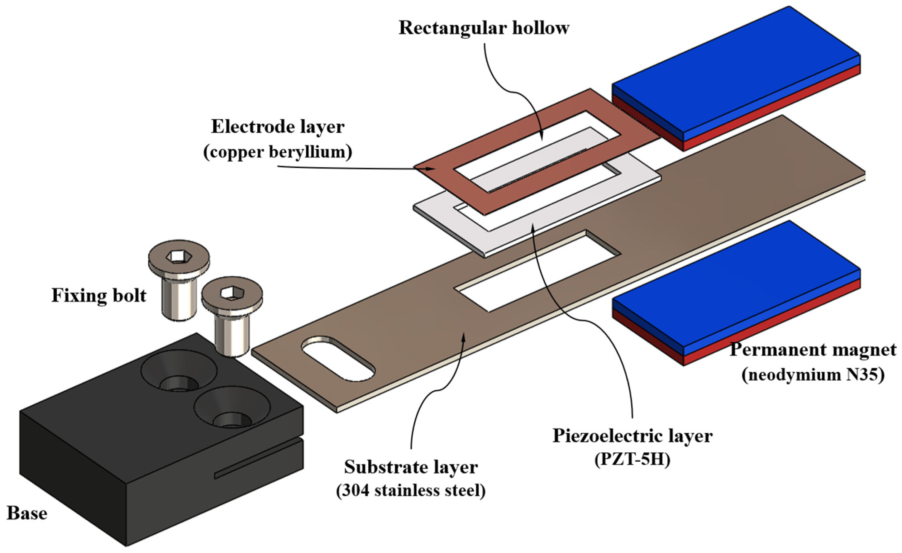
Figure 4. Exploded view of the main components of the pVEH, including the substrate layer, piezoelectric layer, electrode layer, and permanent magnets.
Technologies 13 00194 g004
Figure 5. Geometric parameters of the six sections of the pVEH resonator, which contained different material layers.
Technologies 13 00194 g005
Figure 6. Schematic view of a multilayer cross-section used to calculate the elastic centroid.
Technologies 13 00194 g006
Figure 7. Reaction forces and internal and external loads acting on the pVEH resonator.
Technologies 13 00194 g007
Figure 8. Parametric design for optimization model of pVEH resonator.
Technologies 13 00194 g008
Figure 9. Resonant frequency of the pVEH as a function of the piezoelectric patch position (Lp) and considering different substrate lengths (LT). The x-axis indicates the values of Lp and the y-axis shows the resonant frequency magnitudes of the pVEH.
Technologies 13 00194 g009
Figure 10. Resonant frequency of the pVEH as a function of the rectangular hole width (Hw) and considering different values of the rectangular hole length (HL) and piezoelectric patch position (LP): (a) LP = 1 mm; (b) LP = 3 mm; (c) LP = 5 mm; (d) LP = 7 mm; and (e) LP = 9 mm.
Technologies 13 00194 g010aTechnologies 13 00194 g010b
Figure 11. First four vibration modes of pVEH resonator with their corresponding natural frequencies: (a) first mode at 29.2 Hz, (b) second mode at 308.3 Hz, (c) third mode at 519.9 Hz, and (d) fourth mode at 557.5 Hz. The mode shapes illustrate relative deformation and are not scaled to actual displacement magnitudes. The color scale represents the relative displacement amplitude, with darker shades indicating regions of higher deformation.
Technologies 13 00194 g011
Figure 12. FEM simulation results for pVEH resonator: (a) voltage versus frequency, showing resonance voltage peak; (b) voltage and output power versus load resistance, highlighting optimal load for maximum power transfer; (c) linear fit of von Mises stress versus acceleration, illustrating proportional relationship; (d) voltage versus acceleration.
Technologies 13 00194 g012aTechnologies 13 00194 g012b
Figure 13. Simulation results for the pVEH resonator: (a) the mechanical stress distribution and (b) deflection analysis of the pVEH resonator.
Technologies 13 00194 g013
Figure 14. Deflection profile of the pVEH resonator obtained using the proposed analytical and FEM models of the pVEH resonator.
Technologies 13 00194 g014
Figure 15. Main components of the pVEH system mounted on an induction electric motor.
Technologies 13 00194 g015
Figure 16. Block diagram of the complete energy harvesting and power management architecture for the pVEH system. Red indicates the main electrical components, green represents the signal and power paths, and dashed blue boxes group functional subsystems.
Technologies 13 00194 g016
Table 1. Properties of materials of pVEH components [51,52,53].
Properties Substrate LayerPiezoelectric LayerElectrode Layer Mass
Material 304 stainless steelPZT-5HCopper berylliumNeodymium N35
Young’s modulus (GPa)19363125150
Density (kg/m3)8000750082507400
Poisson’s ratio0.90.310.30.25
Yield strength (MPa)215123.2172-
Tensile strength (MPa)505 469-
Table 2. Geometric parameters and dimensions of the pVEH resonator.
Geometric Parameters Dimensions (mm)Geometric ParametersDimensions (mm)
L11b2S2= b2S4= b1S6= b3S610
L2= L42.5b2S37
L315h1S1= h1S2= h1S3= h1S4= h1S50.6
L549h1S62
L620h2S2= h2S3= h3S40.8
b1S1= b1S2= b1S4= b1S5= b2S312h2S62.6
b1S311h3S64.6
Note: All dimensions are expressed in millimeters (mm).
Table 3. Magnitudes of the structural parameters used in the electromechanical modeling of the pVEH.
Parameters MagnitudeParametersMagnitude
(EI)S1= (EI)S50.063 Nm2w335.119 Nm−1
(EI)S2= (EI)S40.091 Nm2w4284.882 Nm−1
(EI)S30.067 Nm2w511.531 Nm−1
(EI)S618.273 Nm2w6173.441 Nm−1
w1565.056 Nm−1R06.4265 N
w2284.882 Nm−1M00.325 Nm
Table 4. Effect of hole dimensions on voltage generation, stress, and efficiency factor of pVEH.
Layer Position (mm)Hole Length (mm) Hollow Width (mm)Voltage (V)Stress (MPa)Efficiency Factor (V/MPa)
15548.3153.70.31
1153132.6296.30.45
310577.4223.70.35
515587.8230.30.38
Disclaimer/Publisher’s Note: The statements, opinions and data contained in all publications are solely those of the individual author(s) and contributor(s) and not of MDPI and/or the editor(s). MDPI and/or the editor(s) disclaim responsibility for any injury to people or property resulting from any ideas, methods, instructions or products referred to in the content.

