1. Introduction
Micro/nanorobots (MNRs) are widely recognized in various research fields due to their miniature size and versatile structures, offering advantages of flexibility, controllability, adaptability, and effective navigational capabilities [
1]. These miniature agents are becoming increasingly crucial for precision medical applications, enabling advanced treatments, drug delivery, diagnostics, disease detection, and streamlined surgical procedures [
2,
3]. Consequently, research focusing on technologies that empower MNRs to navigate within blood vessels has become a significant focus [
4,
5,
6].
However, the effective actuation and accurate path tracking of MNRs in three-dimensional (3D) and six-dimensional (6D) space remain key challenges, particularly in the context of targeted drug delivery within blood vessels [
7,
8,
9]. Reliable power sources are crucial for maintaining sustained operation and executing tasks efficiently.
MNRs require a power source to operate within their designated environment and complete assigned tasks. A promising approach is internal power generation, such as utilizing bloodstream flow, body temperature, microbial fuel cells, electrogenic bacteria, chemical fuel, or bioreactors [
10,
11,
12]. However, a critical question remains: how much power is required for MNRs to perform actuation and computation tasks effectively? Furthermore, ensuring that internal power generation can sustain prolonged operation and travel within the human body remains an unresolved challenge [
13].
MNRs can be powered by either exogenous sources (e.g., light energy, magnetic fields, electric fields, or acoustic fields) or endogenous sources (e.g., chemical interaction energy) [
7,
13,
14,
15,
16]. Various driving techniques have been explored, including piezoelectric sources [
17], thermal actuation [
18], electro-osmotic forces [
19], biological bacteria-based driving [
20], and chemically powered micro-motors [
21]. Despite their potential, many of these methods face significant limitations, such as cytotoxicity, limited adaptability to biological environments, and inefficient energy transfer [
7].
Among external power sources, electromagnetic actuation (EMA) has gained recognition due to its ability to penetrate deep biological tissues safely while minimizing interactions with living cells [
22,
23]. The EMA surpasses other actuation techniques in terms of controllability, speed, adaptability, and safety profile [
24,
25]. However, achieving precise control, real-time tracking, and stable actuation in high-viscosity, dynamic fluidic environments remains an ongoing challenge [
14,
26,
27]. While studies support the safety of EMA under certain conditions, further assessments are needed to understand the long-term effects of exposure. The Electromagnetic Power and Safety Considerations section discusses these aspects in detail.
Several electromagnetic actuation (EMA) systems have been developed to control MNRs in biomedical applications. Notably, OctoMag and MiniMag represent state-of-the-art EMA platforms yet present key limitations [
28]. OctoMag provides five degrees of freedom (DoF) control, restricting full 6D maneuverability and limiting precise trajectory stabilization in complex, high-viscosity environments. MiniMag, while enabling motion control in 3D, lacks real-time closed-loop feedback and adaptive control, making it less effective for applications that require high-precision targeting, such as drug delivery [
29].
The proposed 6D EMA system overcomes these limitations by integrating three Helmholtz and three Maxwell coil pairs, enabling independent control over six degrees of freedom (three translational and three rotational). The inclusion of real-time tracking and adaptive closed-loop control enhances trajectory accuracy and stability, allowing precise actuation in high-viscosity biological environments. This advancement ensures reliable MNR manipulation across different sizes and configurations, making it more adaptable for biomedical applications, mainly targeted drug delivery.
Recent advancements in electromagnetic actuation (EMA) have significantly improved MNR control precision, adaptability, and real-time feedback capabilities. Hybrid coil configurations and AI-based magnetic field adjustments have been introduced to optimize control for biomedical applications [
8,
30]. However, achieving robust actuation in high-viscosity environments and developing real-time closed-loop tracking solutions remain critical challenges [
9,
31].
Additionally, advancements in untethered MNR propulsion have introduced new methods for precise trajectory control, leveraging adaptive AI-based magnetic fields [
32]. These innovations align with the objectives of this study, which aims to develop a 6D EMA system that integrates real-time tracking, optimized power efficiency, and high-precision actuation in complex fluidic environments.
This study addresses these challenges by proposing a 6D electromagnetic-based actuation (EMA) system to enable the seamless and accurate navigation of MNRs in complex biomedical environments. The following section provides an in-depth review of related actuation technologies, highlighting key contributions from previous research.
The remainder of this paper is organized as follows:
Section 2 explores Electromagnetic Power and Safety Considerations, addressing critical aspects of energy efficiency, power transfer, and safety protocols for MNR systems.
Section 3 reviews the Current State, Challenges, and Advances in Micro/Nanorobot Actuation Systems, identifying key limitations and emerging solutions.
Section 4 focuses on State-of-the-Art Electromagnetic Actuator Systems, including analysis and novel contributions, evaluation of existing technologies, and presentation of the proposed 6D EMA system.
Section 5 elaborates on the
Proposed EMA Structure and Architecture, detailing kinematics, motion control, and control algorithms.
Section 6 presents the Physical Experimental EMA System and Testing, showcasing practical examples and validating results. Finally,
Section 7 concludes the paper and highlights potential directions for future research.
2. Electromagnetic Power and Safety Considerations
Electromagnetic actuation (EMA) has become a leading technique for powering and controlling micro/nanorobots (MNRs) due to its ability to safely penetrate biological tissues while minimizing adverse interactions with living organisms. Research shows that low-frequency magnetic fields interact minimally with biological tissues, even at intensities as high as 8 Tesla (T), with no significant changes observed in participants’ vital signs under controlled exposure conditions [
28]. Furthermore, MRI-based technologies have been routinely used in clinical applications without adverse effects, operating at field strengths of 1.5–2 T [
29].
Different driving techniques face limitations when used in biomedical contexts [
7,
31]. However, external magnetic fields are a reliable and feasible power source for MNRs. Magnetic fields can penetrate deep tissue while remaining biologically inert under standard operating conditions [
22,
23,
33,
34]. Studies involving human participants exposed to magnetic fields up to 8 T reported no significant physiological alterations [
35]. Additionally, MRI systems, which rely on static magnetic fields up to 2 T, have been universally recognized as safe for human use [
36]. These findings align with established safety guidelines from WHO and ICNIRP, reinforcing the suitability of magnetic fields for powering nanorobots in complex biomedical environments [
37,
38,
39].
Despite these positive findings, long-term exposure risks associated with electromagnetic fields remain partially understood. Research gaps persist in evaluating the effects of prolonged and repeated exposure, particularly in dynamic environments involving real-time electromagnetic actuation [
8,
30]. Variables such as exposure frequency, duration, and biological tissue variability require further investigation [
31,
32].
Compliance with international guidelines from organizations such as the WHO and ICNIRP is essential to ensure patient safety and system reliability [
40]. These regulatory frameworks provide standardized thresholds for field intensity, duration, and frequency of exposure, ensuring optimal safety margins in clinical and experimental applications [
41]. Future advancements must focus on real-time exposure monitoring systems, shielding technologies, and improved safety assessment protocols to address current limitations [
32,
41].
In conclusion, electromagnetic actuation (EMA) is a safe and effective power source for MNRs, provided that health and safety guidelines are strictly adhered to and ongoing evaluations continue to refine our understanding of the long-term exposure impacts.
3. Current State, Challenges, and Advances in Micro/Nanorobot Actuation Systems
The previous sections established the significance of electromagnetic actuation (EMA) in addressing power and safety challenges for micro/nanorobots (MNRs). Despite the demonstrated potential of EMA systems, achieving precise actuation, trajectory control, and stability in dynamic, high-viscosity biological environments remain a persistent technical challenge. This section reviews state-of-the-art advancements in EMA technologies, analyzes key technical configurations, and evaluates experimental contributions from existing research. Additionally, it identifies ongoing challenges and discusses the novel 6D EMA system proposed in this study as a step forward in overcoming these limitations.
As shown in
Table 1, electromagnetic actuation (EMA) exhibits superior performance compared to other actuation techniques, particularly in terms of control precision, adaptability, and operational safety [
24,
25,
42]. Unlike bacterial or chemically driven propulsion, which exhibits limited controllability and relies on environmental factors, EMA enables real-time closed-loop control via external field manipulation [
32]. Optical and electrostatic methods, while offering high precision, often face challenges related to surface constraints, localized heating, or energy inefficiencies [
6].
A key advantage of EMA is its deep tissue penetration (~several cm), non-invasive nature, and sub-micrometer positioning accuracy [
24,
25,
42]. This is particularly critical for biomedical applications, where penetration depth and precise movement control dictate the feasibility of real-world implementation [
43]. Compared to other techniques, which are often restricted to millimeter-range or surface-level operations, EMA provides the most viable approach for in vivo applications [
8,
44].
Safety considerations are also essential. Biological and chemical actuation mechanisms may induce cytotoxicity or require reactive chemical inputs [
28], whereas optical methods carry risks of localized tissue heating due to high-intensity lasers [
29]. In contrast, EMA operates within low-frequency ranges (<100 Hz), significantly reducing risks of thermal buildup, bioelectric interference, and tissue damage [
2,
24,
30]. Electromagnetic fields at clinically accepted intensities are routinely used in MRI applications, thereby reinforcing the suitability of EMA for long-term biomedical use [
8,
31].
These characteristics establish EMA as one of the most effective, scalable, and biocompatible actuation strategies for micro/nanorobot (MNR) systems, as detailed in
Table 1.
Table 2 further expands on different EMA configurations, providing a comparative analysis of system scalability, field strength, and tracking capabilities.
Table 2 presents a comparative evaluation of various electromagnetic actuation (EMA) systems, providing insights into their degrees of freedom (DoF), control mechanisms, and biomedical applicability. The proposed 6D EMA system offers key advantages over previous 5-DoF configurations, such as OctoMag and Minimag, by providing fully independent six-axis control (three rotational and three translational degrees of freedom). In contrast, 5-DoF systems often rely on constrained motion models that limit precise trajectory correction in complex, high-viscosity environments.
One major limitation of prior 5-DoF EMA systems is the exclusive reliance on magnetic gradient-based field generation. While this approach is practical for coarse positioning, it introduces spatial field distortions, reducing precision in fine trajectory stabilization. Our system integrates a hybrid Helmholtz-Maxwell configuration, ensuring a uniform and stable field across multiple spatial orientations, reducing unwanted drift, and enabling high-precision motion control.
Additionally, real-time closed-loop tracking, a feature absent in traditional 5-DoF configurations, enables our system to adjust actuation parameters based on MNR feedback dynamically. This is particularly important for biomedical applications such as targeted drug delivery and microsurgical navigation, where minor deviations can impact procedural success. The modular scalability of our system further enhances adaptability, making it suitable for different MNR sizes and clinical applications. These comparative aspects are outlined in
Table 2.
3D Helmholtz coils generate a uniform magnetic field, enabling precise control over motion in both 2D and 3D spaces. These systems offer high stability but exhibit moderate scalability constraints due to their structural design [
45]. In contrast, uniform saddle coils utilize a magnetic gradient, making them practical for 1D motion control, although they face limitations in both stability and scalability within dynamic biological environments [
46].
Advanced systems, such as OctoMag and MiniMag, employ gradient-based control mechanisms, achieving higher degrees of freedom (five DoF and four DoF, respectively) and enabling fine-tuned motion control in 3D spaces. Both systems demonstrate high field strength and stability, but their scalability remains moderately challenging [
47,
48].
Hybrid configurations, such as the one Helmholtz pair + one Saddle pair + motor, integrate static and motorized control mechanisms, facilitating 2D motion control with moderate scalability and field strength [
35]. On the other hand, setups involving two Helmholtz pairs and two Maxwell pairs incorporate hybrid gradient control, supporting complex 2D motion control with exceptional field strength, stability, and scalability [
2,
49].
These comparisons highlight the evolution of electromagnetic actuation systems, emphasizing the shift towards multi-coil gradient-based architectures for enhanced precision, stability, and adaptability. Advanced configurations, particularly OctoMag and two Helmholtz + two Maxwell systems, showcase clear advantages in addressing the technical challenges of MNR actuation in dynamic and high-viscosity biological environments.
The following discussion will build upon these insights by examining key contributions from the existing literature. This section discusses the significant experimental achievements, advancements in control algorithms, and the integration of novel system architectures that have influenced the development of electromagnetic actuation technologies for MNRs.
Previous research has established foundational EMA systems for microrobot actuation, notably those by Martel, Nelson, and Choi. However, these systems exhibit key limitations that have driven the development of our proposed 6D EMA system.
Martel et al. pioneered MRI-based microrobot navigation, leveraging strong magnetic gradients for in vivo control [
50,
51]. However, this approach is constrained by the fixed workspace of the MRI scanner, low temporal resolution, and limited torque control, which reduces actuation precision in dynamic environments. Our 6D EMA system overcomes these constraints with independent coil configurations, providing scalable workspace coverage and real-time adaptive control.
Nelson et al. introduced Helmholtz-Maxwell actuation for microrobot manipulation [
52]. While achieving 3D motion, their system is limited to five DoF (2R + 3T), lacking full six-axis maneuverability for precise trajectory correction. The absence of real-time closed-loop tracking also restricts its adaptability to unpredictable biomedical conditions. Our system integrates fully independent 6-DoF actuation with real-time closed-loop feedback, enhancing motion accuracy and stability.
Choi et al. developed a Maxwell-Helmholtz hybrid actuation platform for microrobot locomotion [
2,
53]. However, it relies on rotational field control, limiting the precise translational movement required for drug delivery applications. Furthermore, the lack of modular scalability constrains its applicability to diverse microrobot sizes. Our 6D EMA system addresses these issues by employing hybrid field control mechanisms, allowing precise positioning and scalability across various MNR configurations.
These evaluations highlight the significant limitations of prior EMA systems, including workspace constraints, DoF limitations, lack of real-time feedback, and reduced adaptability to high-viscosity environments. By integrating six DoF motion control, real-time closed-loop tracking, and scalable Helmholtz-Maxwell configurations, our system provides a robust solution to the current challenges in microrobot navigation for biomedical applications. In a related study, Choi et al. developed an EMA system utilizing two Helmholtz and Maxwell coils to control a cylindrical microrobot [
2,
53]. Further refining this approach, Choi et al. presented a 2D locomotion platform featuring a Maxwell coil along the z-axis and two Helmholtz coils, which enables motion through a radial magnetic gradient [
54].
Building on these advancements, Yu et al. engineered an EMA system comprising three Helmholtz coil pairs, one stationary Maxwell coil pair, and one rotating Maxwell coil pair, designed for a 3 mm spherical robot [
46]. This configuration demonstrated enhanced spatial precision and multi-axis control.
Palagi et al. implemented a two-degrees-of-freedom (DoF) magnetic actuation system tailored for gel-based microrobots [
1]. Subsequently, Lucarini et al. refined this setup to achieve closed-loop control, minimizing the positioning error to 260 µm [
49].
Expanding into 3D locomotion, Song et al. introduced a 3D EMA system designed for cylindrical microrobots [
55]. Zhang et al. extended this work to integrate a closed-loop feedback mechanism, improving trajectory accuracy [
56].
Xu et al. and Temel et al. focused on 3D spiral microrobot actuation, employing three Helmholtz coils to achieve multidimensional control with improved efficiency [
57,
58].
Meanwhile, Ramos et al. designed a 3D EMA system utilizing three Helmholtz and three Maxwell coils, providing spherical microrobots with highly flexible 3D motion capabilities [
59].
These studies highlight the evolution of electromagnetic actuation technologies, showcasing a progressive trend towards multi-axis control, spatial precision, and adaptability in biological environments. Integrating Helmholtz and Maxwell coil systems has proven effective in achieving consistent and precise control across diverse operational scenarios.
The comparative analysis presented in
Table 3 illustrates the evolution of electromagnetic actuation (EMA) systems from early 1D MRI-based designs to advanced 3D multi-axis architectures. The table reveals key differences in dimensionality, microrobot structure, and size, highlighting trends in design choices and control mechanisms. Advanced configurations, particularly those incorporating Helmholtz and Maxwell coil pairs, demonstrate enhanced spatial precision, stability, and adaptability in dynamic environments. However, scalability, energy efficiency, and consistent performance under fluidic conditions remain persistent challenges across most systems. These insights underscore the need for further innovation in EMA technologies, setting the stage for a subsequent discussion on a novel 6D EMA system designed to effectively address these limitations.
4. Paper Contributions
This section outlines the key contributions of this paper, emphasizing the innovative aspects of the developed 6D electromagnetic-based actuation (EMA) system and its capabilities.
4.1. Cost-Effective 6D Electromagnetic-Based Actuation System
This study introduces a 6D EMA system that balances the precision of micro/nanorobots, affordability, and maintaining cost efficiency. The system has been designed, implemented, tested, and optimized for cost efficiency without compromising performance. This ensures a scalable and economically viable platform for microrobot control in fluidic environments.
4.2. Integrated Helmholtz and Maxwell Coil Architecture
Unlike traditional Helmholtz-only systems, the developed EMA system integrates three Helmholtz and three Maxwell coils, enabling dynamic and accurate microrobot actuation in six spatial dimensions (6D). The system’s architecture combines simulation precision, robust hardware integration, and adaptive software control, achieving high accuracy and real-time responsiveness.
4.3. Six-Dimensional Navigation with Real-Time Tracking
The developed system enables real-time six-dimensional (6D) navigation, enhancing precise microrobot control across three positional axes (x, y, z) and three rotational axes (yaw, pitch, roll). This functionality facilitates complex maneuvers, adaptive control, and seamless navigation in dynamic fluidic environments.
4.4. Large Navigation Region of Interest (ROI)
The developed EMA-based system enables micro/nanorobot navigation within a large Region of Interest (ROI) spanning 40 × 40 × 40 mm3, ensuring a uniform magnetic field is generated across 1D, 2D, and 3D configurations that provide consistent spatial coverage, allowing microrobots to execute tasks across extended workspaces with high stability.
4.5. Adaptability Across Multiple Microrobot Sizes
The developed system supports microrobot actuation across various sizes (0.5 mm to several mm), validating its scalability and adaptability across different microrobot geometries and dimensions and confirming its consistent performance in diverse experimental conditions.
4.6. Experimental Validation and Precision Analysis
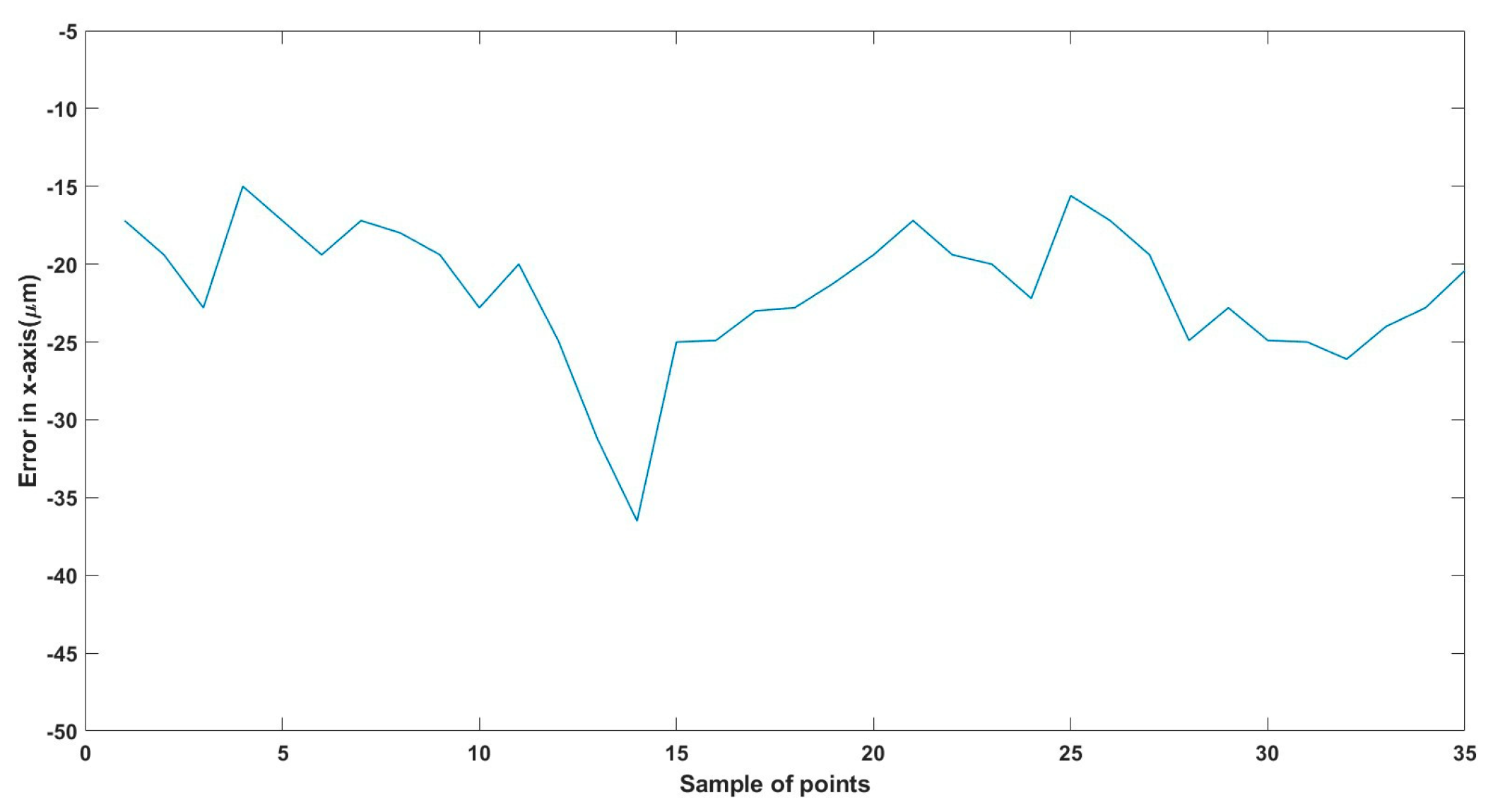
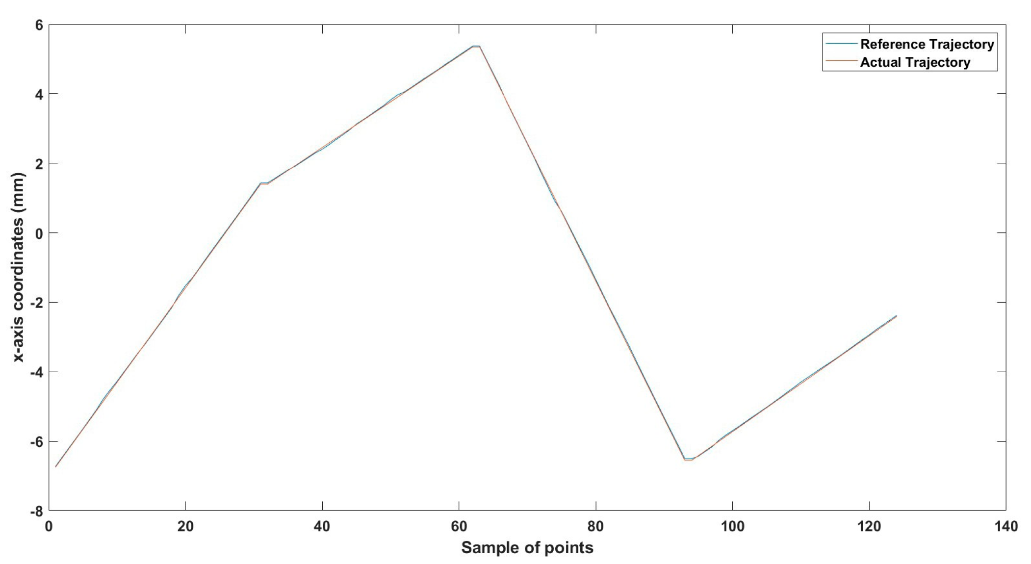
Extensive experimental validation demonstrated high precision with minimal positioning errors across various trajectories and environmental setups, including different robot sizes.
Smaller Microrobots (0.5 mm length, 0.3 mm diameter): Positioning errors were recorded at 36 µm (x-axis), 32 µm (y-axis), and 33 µm (z-axis).
Larger Microrobots (1.5 mm length, 1 mm diameter): Positioning errors were measured at 35 µm (x-axis), 24 µm (y-axis), and 28 µm (z-axis).
These results demonstrate the system’s reliability, precision, and adaptability in managing complex microrobot trajectories under varying fluidic conditions.
4.7. Insights into Challenges and System Optimization
This study provides in-depth insights into addressing the challenges of microrobot actuation, including magnetic field uniformity, trajectory stability, scalability, and control precision. The iterative refinement of the EMA system, combined with detailed experimental analysis, contributes to a robust and adaptable platform for future biomedical and industrial microrobot applications.
5. Design of the Driving EMA
5.1. Mathematical Modelling
For any electromagnetically actuated MNR, the robot object is subjected to torque and force in the generated magnetic field. The magnetic torque is directly correlated with the magnetic field intensity and acts to align the MNR’s internal magnetization with the field. In contrast, the magnetic propulsion force is proportional to the gradient of the magnetic field and serves to move the robot toward regions of increasing field strength, as described by the following equations [
1,
60,
61]:
where
V represents the volume of the MNR,
M represents its magnetization saturation, and
B represents magnetic flux density.
A compact device for generating uniform and sustained magnetic fields and gradients consisting of a 3D configuration of Helmholtz and 3D Maxwell coils was designed and built to steer and navigate the MNRs by utilizing controlled magnetic torque and force. The developed EMA is shown in
Figure 1, and its configuration provides the following functionalities:
Three orthogonal pairs of Helmholtz coils generate a uniform magnetic field, which serves to magnetize and steer the MNR;
Three orthogonal pairs of Maxwell coils generate a uniform field gradient, providing propulsion.
The following equations describe the magnetic field and its gradient due to a controlled current flowing through the coils. These equations allow the calculation of the magnetic field produced by each Helmholtz coil pair and the magnetic field gradient generated by each Maxwell coil pair at the system’s central region, which encompasses the entire arena [
60,
61]:
where
µo is the permeability of the space,
kx and
gx are constants determined by the coil’s geometric properties,
NH and
NM are the numbers of turns, and
rH and
rM are the radii of the Helmholtz and Maxwell coils, respectively. Thus, the total magnetic field generated by the three Helmholtz coil pairs and the field gradients by the three pairs of Maxwell coils in the 3D (x-y-z) coordinate space can be expressed as [
61]:
The parameters kx, ky, and kz represent the magnetic field generation coefficients for the Helmholtz coils in the x, y, and z directions, respectively. These parameters define how Helmholtz coils are used to generate a uniform magnetic field in a controlled manner when a current IH is applied. Additionally, these parameters are either empirical or calculated coefficients that describe the efficiency with which the Helmholtz coils generate a uniform magnetic field. The values depend on the coil radius, number of turns, and geometry.
The primary role of the Helmholtz coil-generated field is to:
Control the orientation of the MNR by applying a torque that aligns its magnetic moment with the applied field.
Stabilize the magnetic environment to ensure consistent MNR orientation without unintended drift.
Enable rotational control, allowing the MNR to change its heading direction in response to time-varying field inputs.
Thus, the Helmholtz coils do not directly produce propulsion forces but instead ensure the correct control alignment of the MNR, allowing the propulsion forces generated by the Maxwell coils to act in the desired direction.
The parameters gx, gy, and gz describe how efficiently Maxwell coils generate magnetic field gradients. These parameters depend on the coil design, separation distance, and number of turns, which define how the magnetic field strength changes spatially. Unlike Helmholtz coils, which create a uniform field, Maxwell coils generate a controlled spatial variation in field strength, which induces a magnetic force that moves the MNR. This occurs because a magnetic moment in a field gradient experiences a force, given by Equation (2).
Since the propulsion force is directly proportional to the field gradient ∇B, Maxwell coils are responsible for generating propulsion forces. Their function is to:
Create controlled magnetic field gradients, which exert a net force on the MNR.
Enable propulsion and actuation, allowing movement in the x, y, or z directions.
Be dynamically adjusted, enabling the MNR to change speed and direction by modifying the applied coil currents.
Since motion requires a gradient rather than a uniform field, Maxwell coils are the primary contributors to propulsion, ensuring precise control of the MNR’s movement.
In addition to the axial magnetic field gradient, Maxwell coils also generate a radial gradient component, where the radial gradient is half the value of the axial uniform gradient [
2]. This effect arises due to the symmetry of the Maxwell coil design, where the coil pairs are arranged to evenly distribute the magnetic field gradient.
As a result of this symmetry, the gradient components in the x and y directions are equal, i.e., gx = gy. This assumption simplifies the force model, ensuring that the microrobot experiences a uniform gradient effect in both horizontal directions. However, gz is independent and is not affected by this radial constraint, as it represents the dominant axial gradient in the system.
While the gradient along each axis is primarily dictated by its corresponding Maxwell coil pair, the total gradient field also includes radial contributions from the other two axes. This is reflected in the off-diagonal terms (−0.5 coefficients) in Equation (6), which represent how each axis is influenced by the gradients from the other two directions.
Although gz is independent, it still contributes to the field gradients in x and y through a weaker interaction (−0.5 gz), due to electromagnetic symmetry in the coil setup. Likewise, the field gradients along x and y also contribute weakly to z, leading to the −0.5 gx, −0.5 gy terms in the z-gradient equation.
The full 3D magnetic field gradient, considering these axial and radial components, is given by:
Equation (6) describes the spatial variation of the magnetic field gradient generated by three Maxwell coil pairs. The matrix formulation highlights how axial and radial components interact to influence the microrobot’s motion.
In Equation (6), the terms gx, gy, and gz represent the magnetic field gradient components along the x, y, and z axes, respectively. These coefficients define how the applied current influences the net magnetic field gradients generated by the Maxwell coils in each direction.
On the other hand, the variables x, y, and z in the equation correspond to spatial coordinates within the region of interest (ROI). These represent the position of the microrobot in Cartesian space and are not to be confused with the field gradient coefficients. The interaction between the field gradients gx, gy, and gz and the spatial coordinates x, y, and z determines the net magnetic force applied to the microrobot, ensuring precise control over its movement.
The diagonal terms (gx, gy, gz) represent direct contributions to the field gradient along each axis.
The off-diagonal terms (−0.5 coefficients) represent radial interactions, showing how the other two directions influence each axis’ field gradient.
Since Maxwell coils are engineered to generate symmetric gradients in the horizontal plane, the assumption gx = gy simplifies the force modeling. However, gz remains independent, as it corresponds to the axial propulsion field.
This formulation is crucial for understanding how precise coil current control influences MNR propulsion, enabling real-time actuation in a controlled direction.
5.2. Analysis of Uniformity of Magnetic Field
To control the actuation of an MNR under the effect of a magnetic field, a 3D EMA coil system must offer a controllable magnetic field in 3D space. Adjusting the currents that flow through the coils can control the magnetic field produced by the coils and, consequently, the motion of the magnetic MNR. The main concept of the proposed EMA, a 3D EMA system, is constructed by arranging three sets of Helmholtz coils and three sets of Maxwell coils along three orthogonal axes. A uniform magnetic field is produced by Helmholtz coils, whereas Maxwell coils generate a uniform and sustained magnetic field gradient. Therefore, Helmholtz coils control the MNR’s orientation, and Maxwell coils control its motion and activation. Finite element analysis was conducted to verify the uniformity of the magnetic field generated from both Helmholtz and Maxwell coils and along each of their axes, as we reported in our previous work [
24,
25].
5.3. Simulation and Coils Parameters
The sizes and configuration of the coil systems were considered when designing the entire system to situate the ROI, which is 40 × 40 × 40 mm
3, inside the Helmholtz and Maxwell coils. The Helmholtz coil’s diameter is also intended to be different from the Maxwell coil’s to reduce space restrictions. Because of this, each coil pair meets the requirements for a coil pair despite having a different diameter from the others. Finally, the placement and the number of coil turns are selected so that each pair of Maxwell coils (
Mx,
My, and
Mz) and each pair of Helmholtz coils (
Hx,
Hy, and
Hz) has the same gradient of magnetic flux with the same current.
Table 4 summarizes the coil system’s specifications [
62,
63].
The coil dimensions presented in
Table 4 were chosen to optimize magnetic field generation, uniformity, and actuation efficiency while balancing power consumption and workspace coverage. The Helmholtz (
Hx) and Helmholtz (
Hy) coils have a radius of 50 mm, which ensures a homogeneous field in the XY plane while maintaining a compact footprint for precision-based control. In contrast, the Helmholtz (
HZ) coil has a larger 125 mm radius, which is necessary to generate a sufficiently strong and uniform field in the vertical (Z) axis, compensating for the natural attenuation of magnetic field strength in this direction due to workspace depth.
Maxwell coil dimensions were similarly selected based on gradient field generation requirements. The coil spacing and winding density were optimized to ensure smooth transitions in force application without field distortions, ensuring robust six-degree-of-freedom (6-DoF) control across the entire operational volume. These design considerations collectively enhance system stability, precision, and adaptability for microrobot actuation in dynamic biological environments.
The spatial field distribution and gradient uniformity of the electromagnetic actuation (EMA) system were validated through numerical analysis, as detailed in [
62,
63]. These studies confirmed that the Maxwell coil configuration generates a uniform gradient field, ensuring precise control over microrobot movement while maintaining minimal spatial field distortions. The uniformity of the generated field plays a crucial role in maintaining stable and repeatable microrobot actuation, particularly in dynamic fluidic environments.
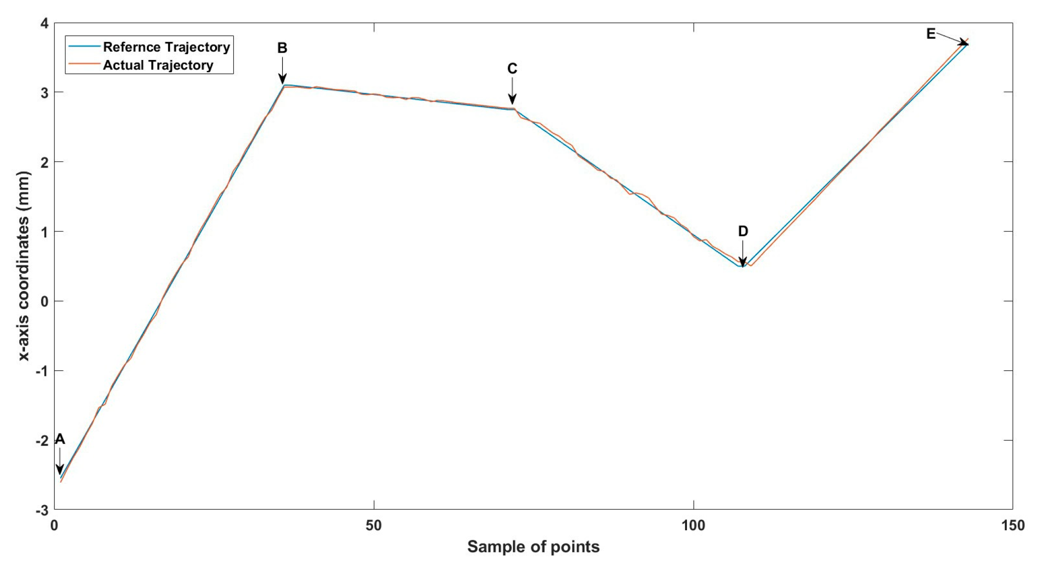
Additionally, the trajectory tracking performance of the system was validated through simulation studies in [
61], demonstrating the effectiveness of the closed-loop control approach. The study confirmed that a 3D electromagnetic actuation system comprising three pairs of Helmholtz and Maxwell coils could navigate microrobots with high precision, achieving trajectory tracking errors as low as 13 µm.
These results were obtained using a closed-loop control strategy, where real-time adjustments to coil currents ensured accurate trajectory following and minimal deviation from the desired path. The PID-based control system in the simulation dynamically regulated the field gradients to compensate for external disturbances, improving overall stability and positioning accuracy.
Figures 8–15 illustrate the simulated trajectory tracking results, demonstrating that the closed-loop system effectively maintains microrobot stability and minimizes trajectory errors in real-time. These simulations confirm that the proposed system can provide robust six-degree-of-freedom (6-DoF) control, ensuring reliable microrobot actuation in complex biomedical environments.
While the present study focuses on experimental validation, these prior simulations substantiate the system’s accuracy, real-time adaptability, and closed-loop control efficiency, reinforcing its suitability for biomedical applications, such as targeted drug delivery and minimally invasive micromanipulation.
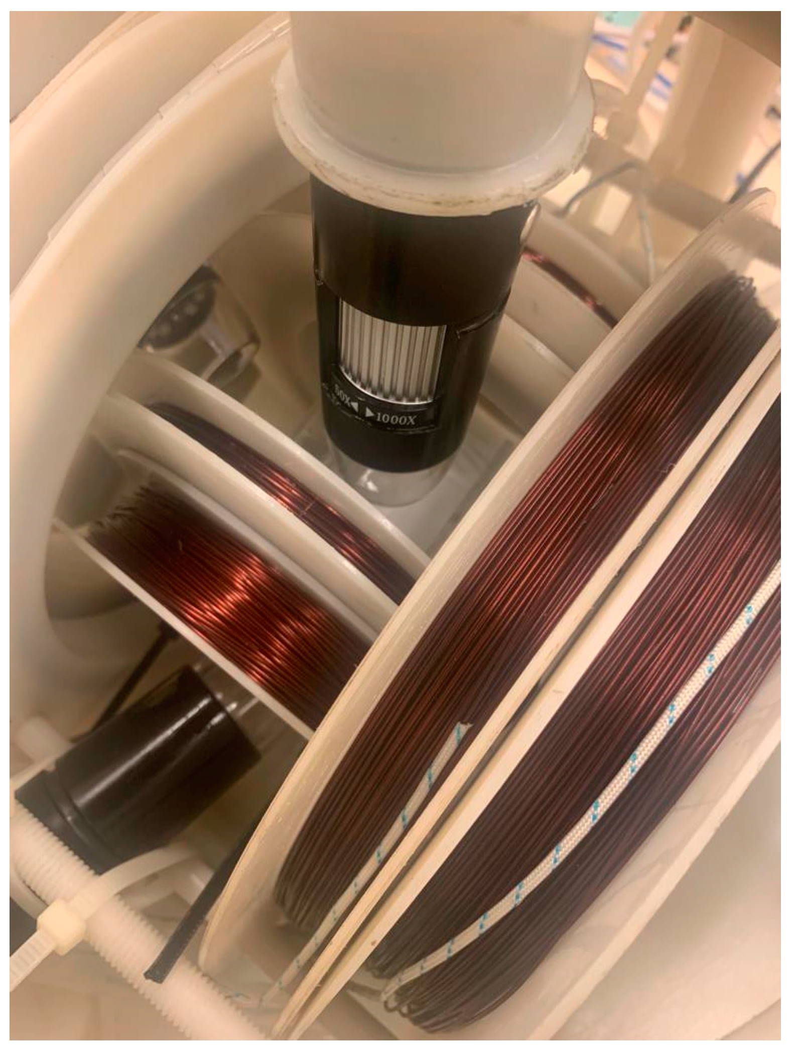
Figure 2 shows the coils after manufacturing and implementation.
5.4. Closed-Loop Control of EMA
The MNR is aligned to the desired direction in the x-y plane by applying a uniform magnetic field generated by the two orthogonal Helmholtz coil pairs. Taking
θ as the desired orientation angle, the following relationship holds:
Therefore, if both
ky and
kx have the same value, the coil currents can be adjusted to align the MNR with the desired orientation in the X-Y plane. However, for full 3-D navigation, two additional angles must be considered.
The MNR achieves propulsion through the magnetic field gradient generated by three orthogonal pairs of Maxwell coils. These coils create a spatially varying magnetic field, activating the MNR’s magnetic moment and enabling movement. The three force components driving the MNR along the
x,
y, and
z directions are derived as follows:
where
Equation (10) defines the relationship between the propulsion force F, the magnetic moment M, the transformation matrix T (which accounts for the angular orientation angles θ, β, α following Euler angles transformation, T = Rx(α)Ry(β)Rz(θ)), and the magnetic field gradient Vg.
To determine
θ,
β,
α, from the known properties of the generated transformation matrix
T.
Since the magnetic field gradient,
Vg , is produced by the Maxwell coil, it is directly related to the coil-generated gradient ∇
BM:
For the MNR to be effectively controlled and propelled in the desired direction, the ratio of propulsion forces in the x and y directions must satisfy:
Since Maxwell coils in the x and y directions generate equal magnetic field gradients, it follows that gx = gx is deduced, and gm leads to a generalized magnetic gradient constant gm = gx = gy.
Since the gravitational and buoyant forces acting in the z-direction are both constant, the net force in the z-direction, Fzg, consists of Fzg, a force component that balances the gravitational and buoyant forces, and Fzd, a force component that serves as the magnetic driving force along the z-axis. Thus, the total driving force in the z-direction is Fz = Fzg + Fzd.
Similarly, the magnetic field gradient gz in the z-direction comprises gzg, the field gradient required to counteract gravity and buoyancy forces, and gzd, the field gradient required for MNR propulsion along z. This means that gz = gzg + gzd.
Fz is subdivided into
Fzg and
Fzd, with
Fzg balancing the gravitational and buoyant forces and
Fzd serving as the z-axis’ magnetic driving force. The magnetic flux gradient,
gz, is further subdivided into
gzg, which opposes the gravitational force, and
gzd, the magnetic gradient used to actuate the MNR. These relationships lead to the following governing equations: [
55].
Since gzd and gm are both magnetic field gradient components but represent different spatial effects, this equation serves as a normalization constraint, ensuring that the vertical propulsion gradient gzd is balanced correctly with the total field gradient gm. The equation enforces a geometric proportionality, ensuring that the propulsion forces maintain a correct force-to-field ratio in the z-direction while aligning with the overall field gradient structure.
The force
Fzg is responsible for counteracting the gravitational and buoyant forces acting on the MNR, ensuring that it remains stable at a given height before propulsion is applied. This is expressed as:
Fb is the buoyancy force,
ρ f is the fluid density, and
ρ is the MNR’s density. The alignment of an MNR to the required orientation (
β) requires that
gzd =
gm, which may be inferred from Equation (13). The current
Imz is split into two components, one of which generates
Fzg to hold and lock the MNR at any point along the z-axis and the other of which generates (
gzd)
Fzd to activate the MNR in a vertical position. This calculation and keeping of
Fzg as a constant value are carried out using Equation (14) [
61].
7. Conclusions
This paper investigated developing and implementing a low-cost six-dimensional Electromagnetic Actuation (EMA) system to precisely manipulate micro/nanorobots (MNRs) within complex fluidic environments. This innovative approach addresses a significant gap in existing MNR actuation technologies, particularly in high-viscosity environments like those found in biomedical applications.
The heart of this system is the integration of three pairs of Helmholtz coils and three pairs of Maxwell coils, which together create a highly controllable and adaptable magnetic field essential for precise MNR manipulation.
By incorporating a closed-loop Proportional-Integral-Derivative (PID) control technique and real-time visual feedback from three digital microscopes across distinct planes, our EMA system demonstrates its potential to navigate and manipulate MNRs effectively. The effectiveness of the PID control in enhancing the system’s accuracy and responsiveness highlights its suitability for delicate and precise operations required in biomedical applications.
Notably, the system’s region of interest (ROI) spanning a volume of 40 × 40 × 40 mm3 provides significant experimental space for testing and validation. This substantial ROI enables the simulation of various navigational challenges and scenarios MNRs may encounter in real-world applications. However, it is essential to recognize that this scale does not apply to the dimensions of the entire human body. Future work will involve scaling up the system to accommodate larger areas aligned with magnetic resonance imaging (MRI) dimensions to more accurately simulate conditions within the human body. This research marks a good advancement in micro/nanorobotics, setting a foundation for future developments and applications in targeted drug delivery and precision medical diagnostics.
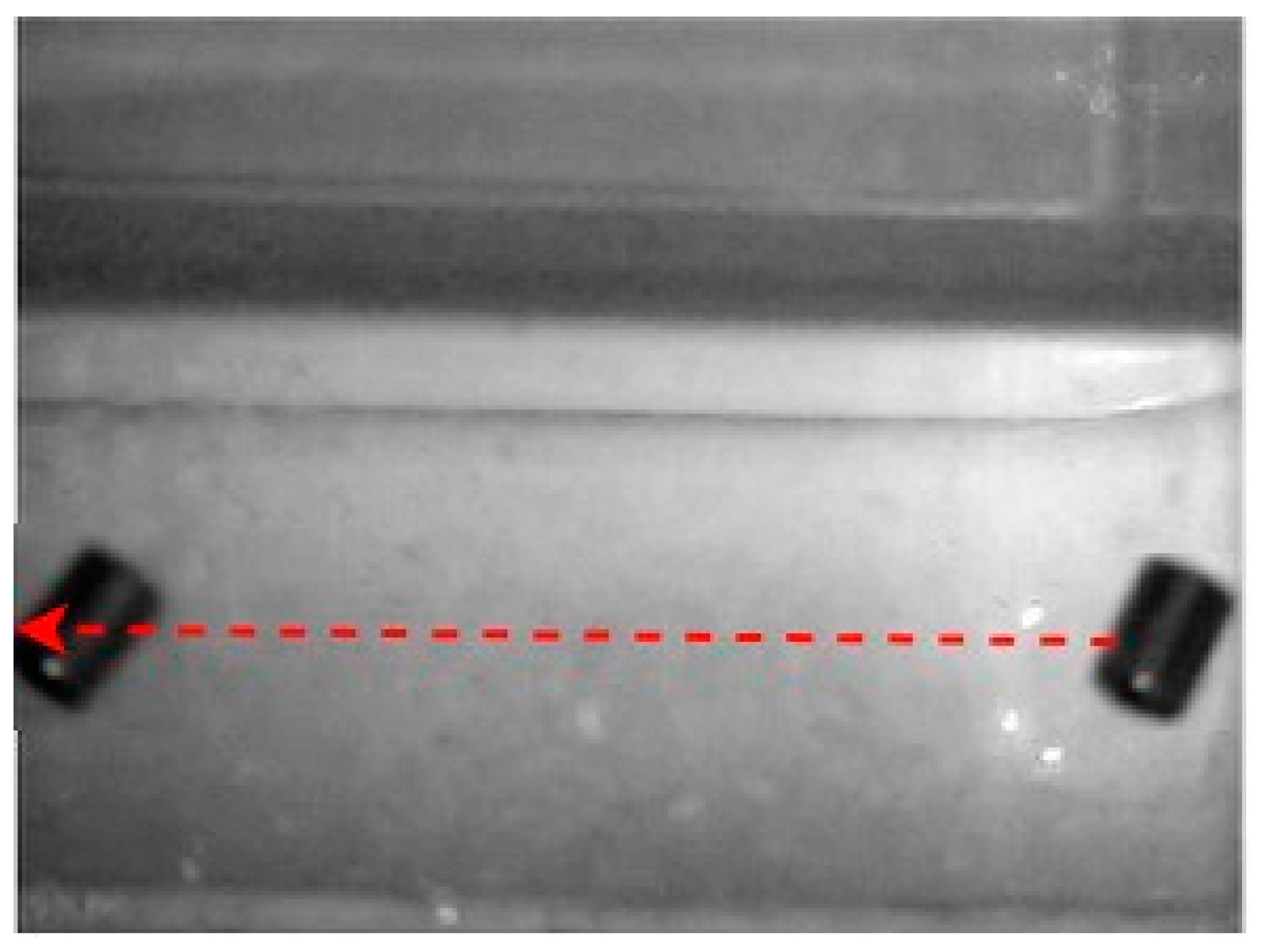
To replicate the dense nature of human blood, we utilized silicone oil within the ROI, enabling us to closely mimic the challenges posed by fluid dynamics in a biological environment. We conducted a series of meticulously designed experiments using two different sizes of MNRs, effectively showcasing the system’s ability to actuate these agents within desired trajectories. The experimental outcomes confirm the system’s proficiency in achieving this goal, with a maximum error of 46 µm observed across the trials.
However, we also identified two main factors that impact the precision of the EMA system: the resolution of the utilized digital microscopes and the radial effect of the Maxwell coils. We recommend enhancing system performance by replacing the existing microscopes with higher-resolution alternatives. Moreover, addressing the radial effect of the Maxwell coils is essential to further reducing errors and improving overall accuracy.
Additionally, given the potential challenges associated with the presence of neodymium-based microrobots in the human body, retrieval strategies must be carefully considered. One proposed solution is to reverse the trajectory of the microrobot, guiding it back to the insertion point for safe extraction. An alternative approach is to develop microrobots from biodegradable materials, allowing them to safely degrade after completing their intended function. While this study focuses on laboratory testing, future work will explore biocompatible materials and ensure compliance with biomedical safety regulations.
It is important to note that the current EMA system dimensions are designed for experimental and laboratory testing purposes rather than full-body biomedical applications. To achieve real-world clinical implementation, a significantly larger system—similar to the scale of Magnetic Resonance Imaging (MRI) devices—would be required. Future research will focus on scaling up the system while ensuring precision and control remain effective for microrobot actuation in the human body.
In conclusion, our work has introduced a novel and cost-effective solution for the precise control and navigation of MNRs in three-dimensional space. By addressing the challenges of fluid dynamics and gravitational forces, we have established the foundation for advancing biomedical applications by manipulating MNRs. This research opens the way for future developments, facilitating more complex and effective interventions within targeted drug delivery, diagnostics, and other precision biomedical procedures.


