
Enhancing Performance of Millimeter Wave MIMO Antenna with a Decoupling and Common Defected Ground Approach
 ,
,  ,
,  and
and
Abstract
1. Introduction
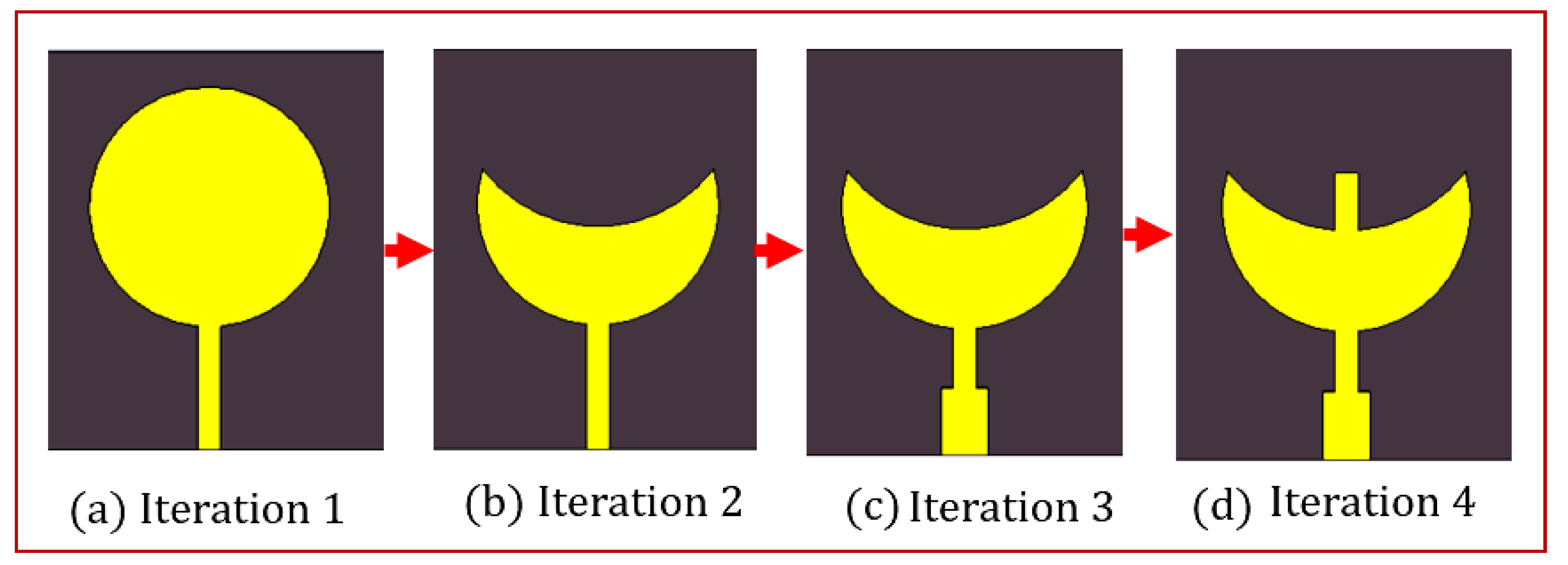
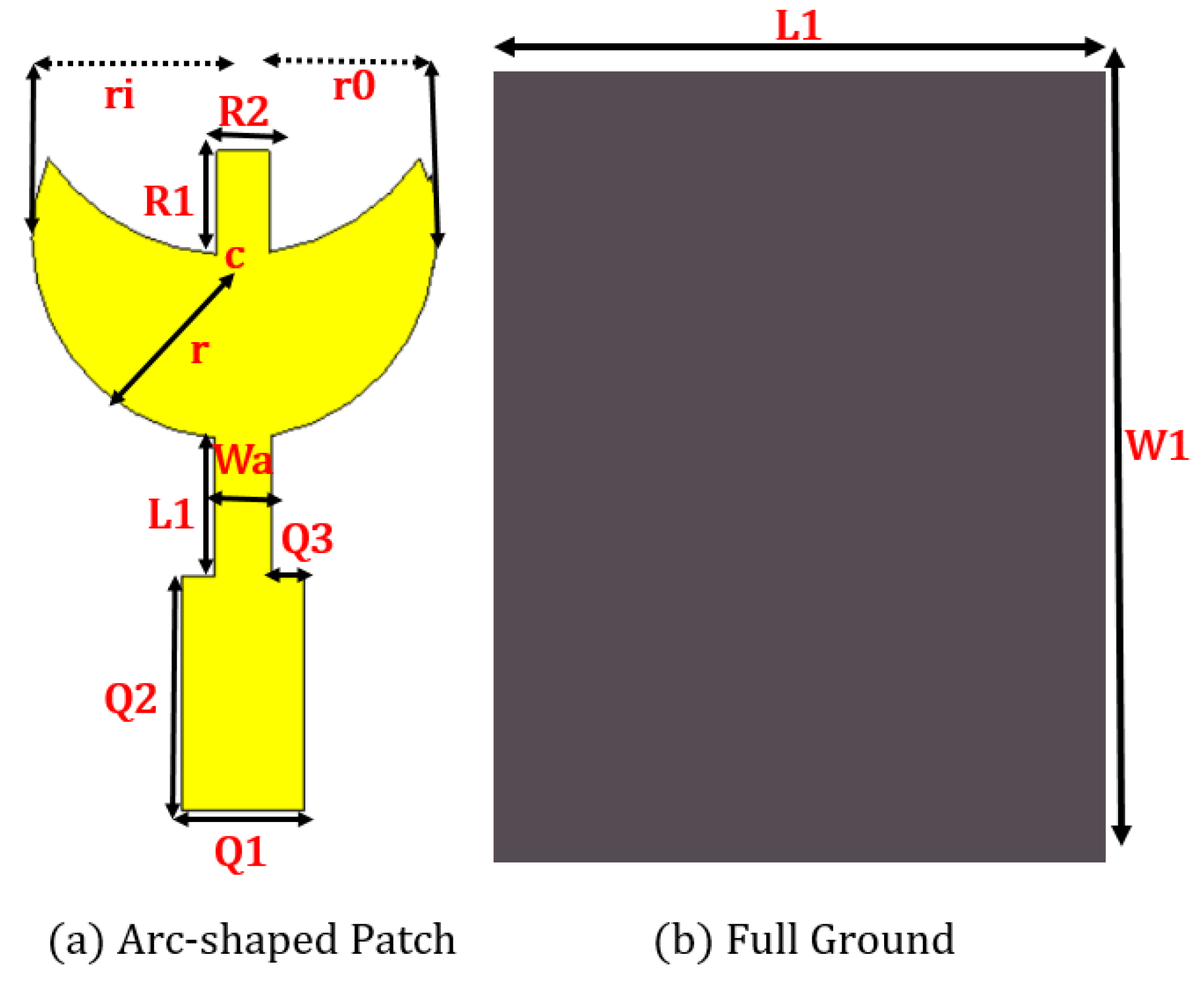
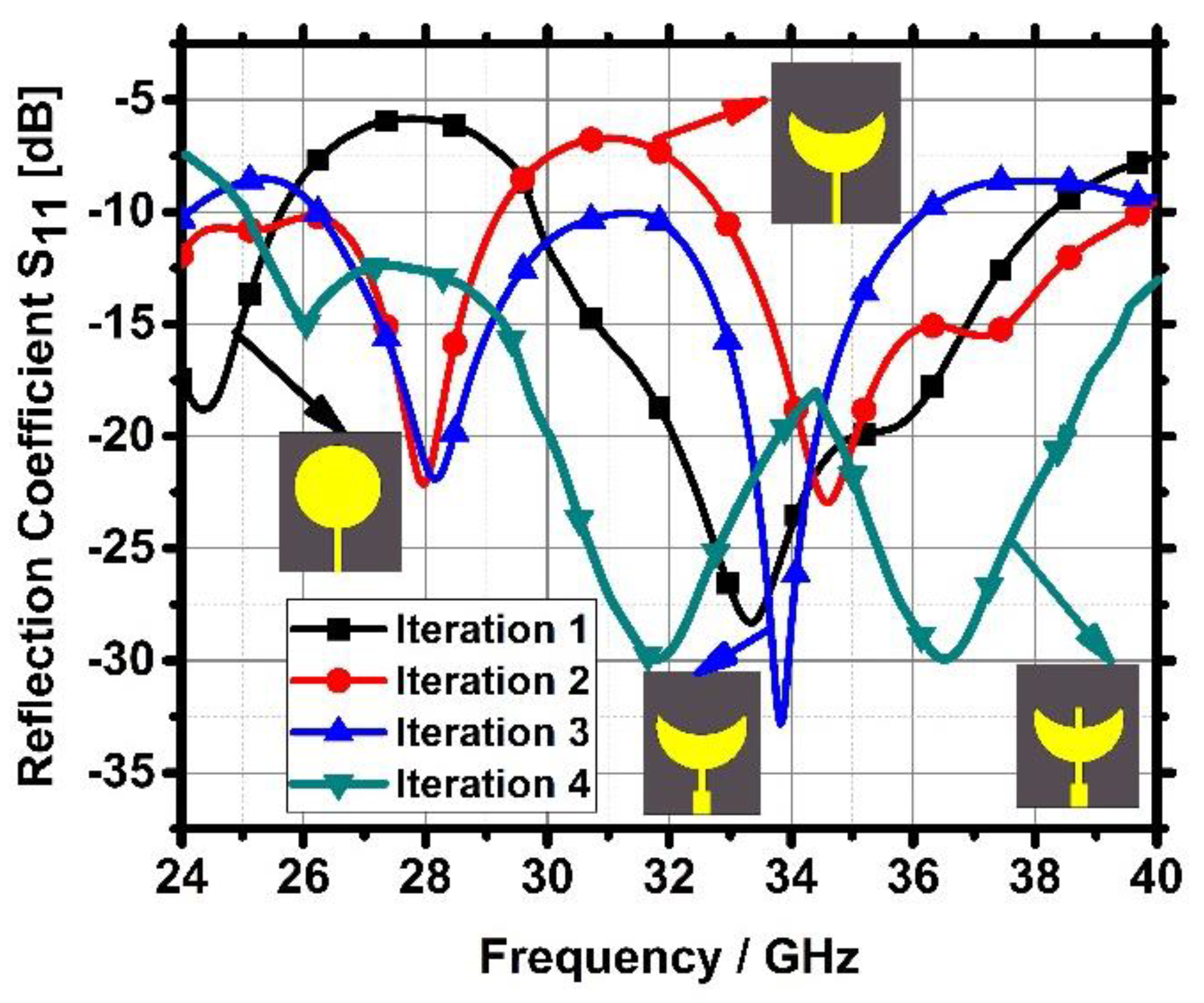
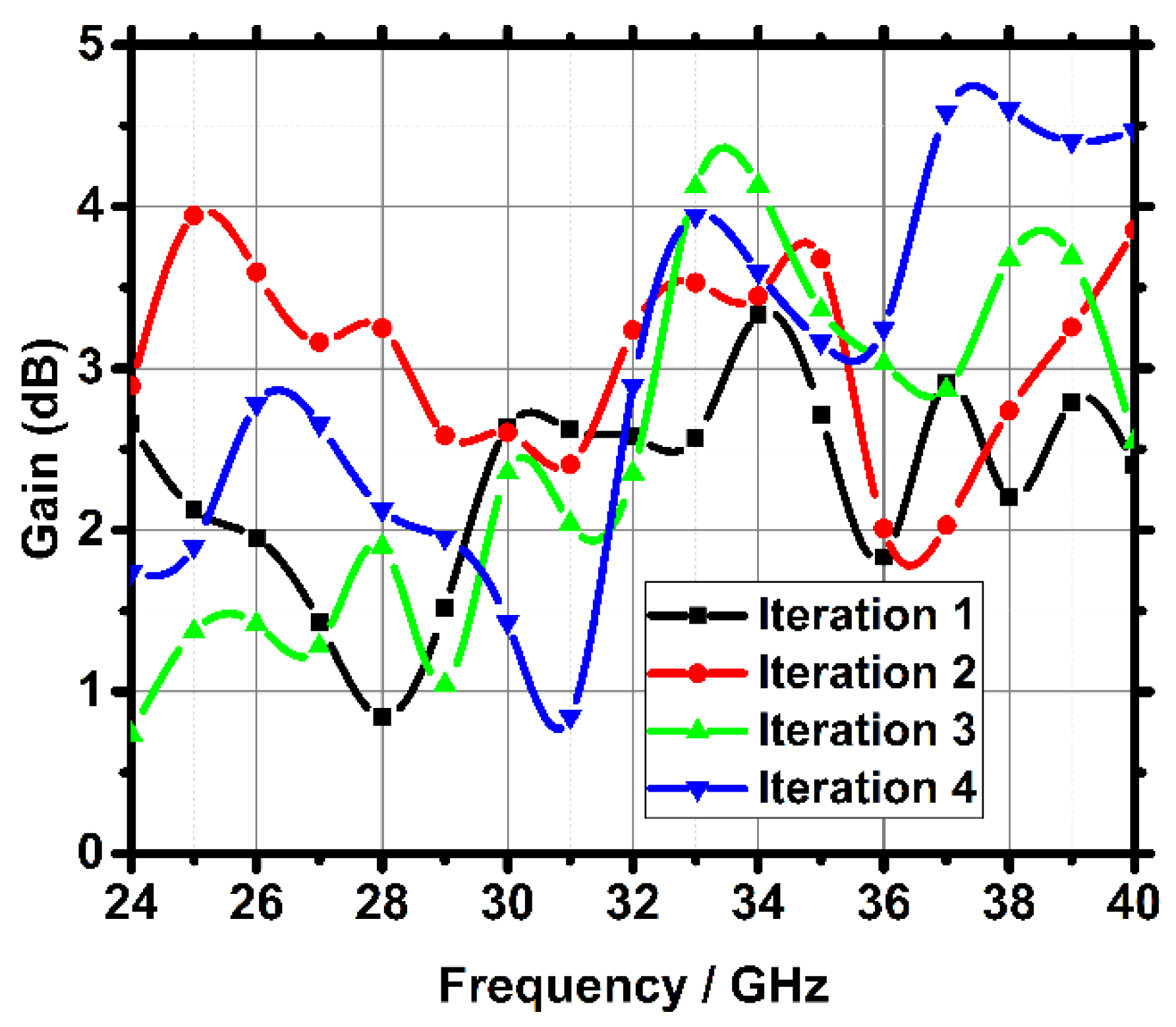
2. Design Evolution of Single Antenna Configuration
3. Parametric Analysis of Single Antenna
4. MIMO Antenna Configuration
5. Parametric Analysis of MIMO Antenna
6. Measurement Performance
6.1. Scattering Parameters
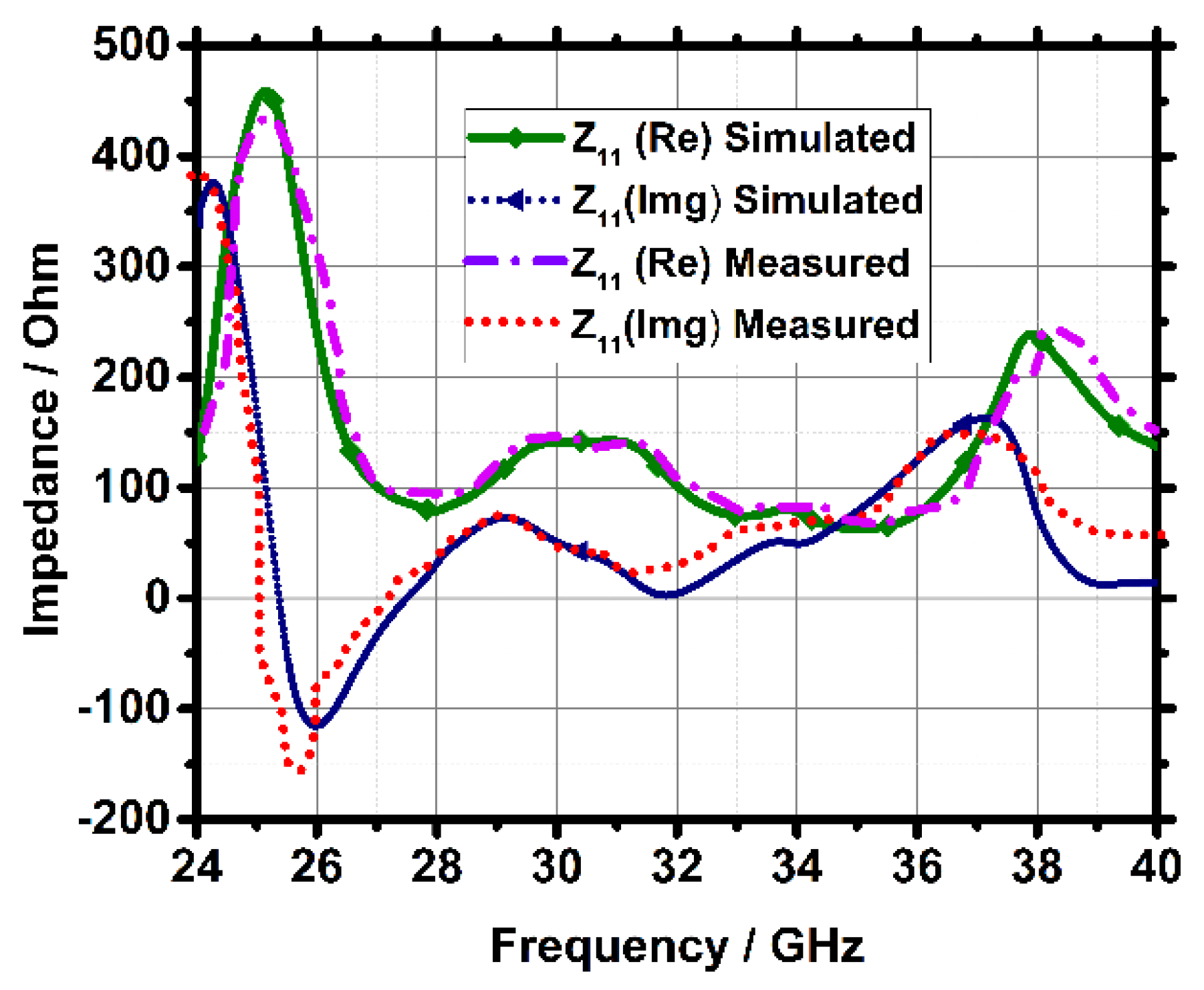
6.2. Z-Parameter
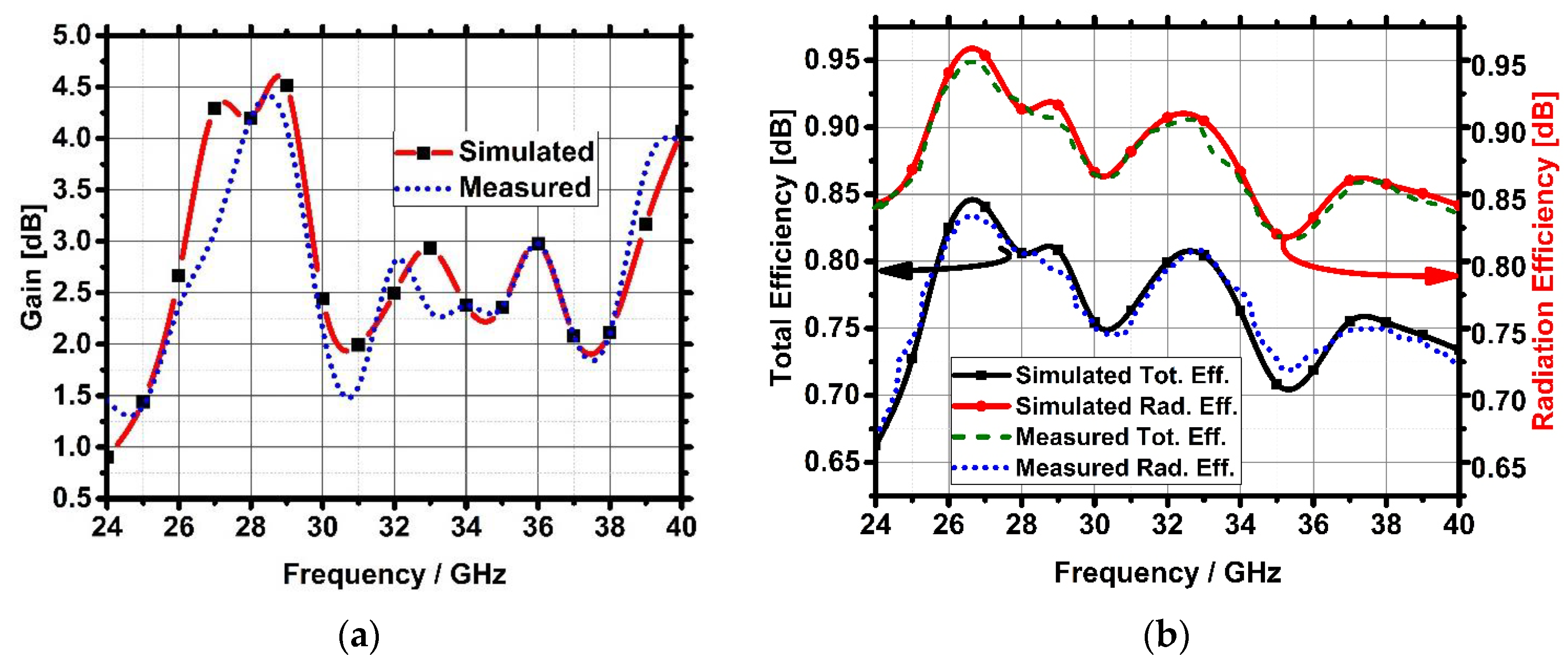
6.3. Gain and Efficiency
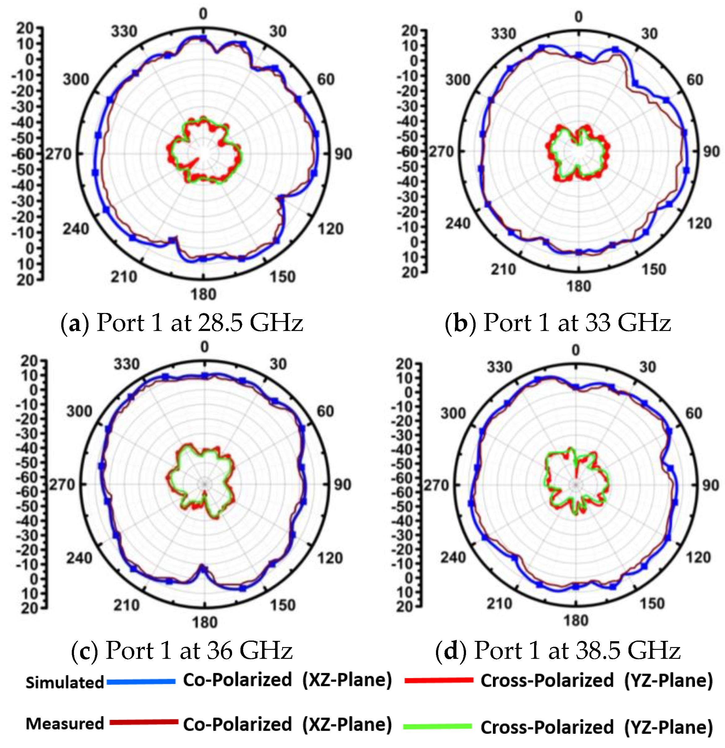
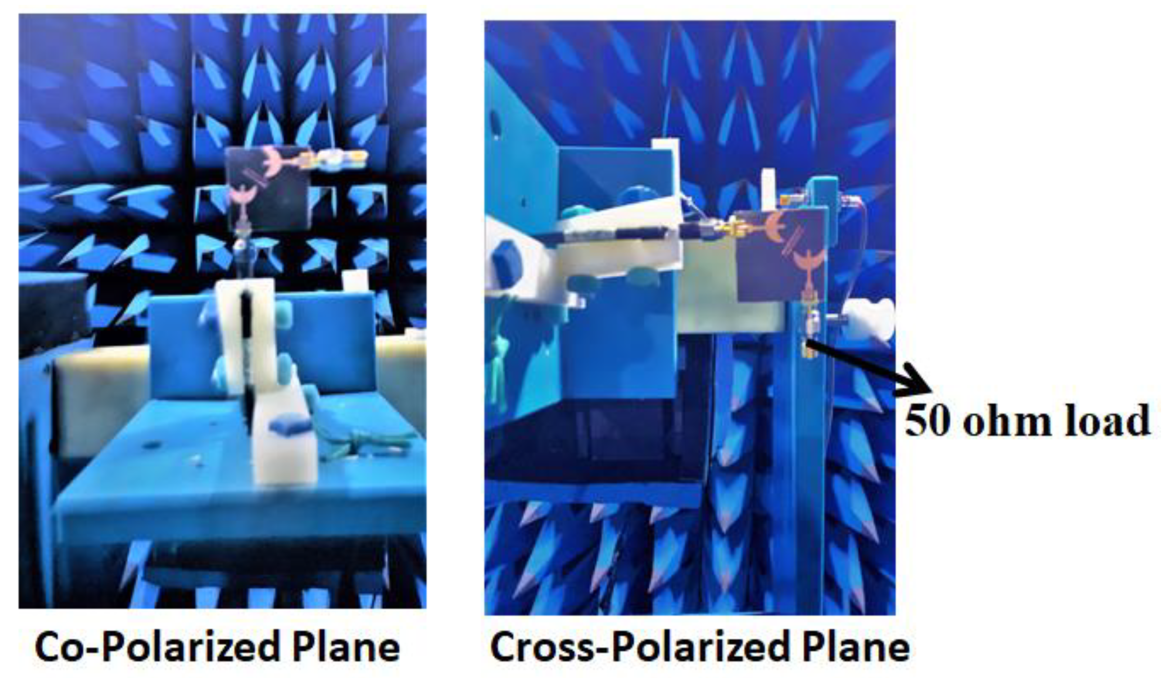
6.4. Radiation Patterns
7. Diversity Characteristics
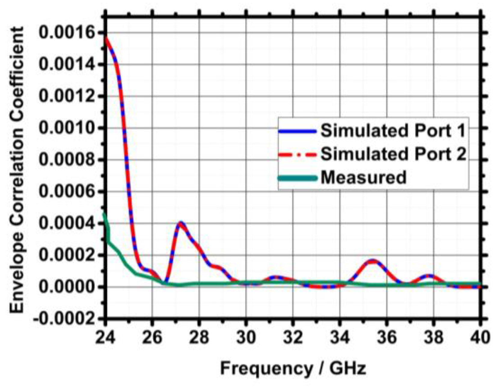
7.1. Envelope Correlation Coefficient
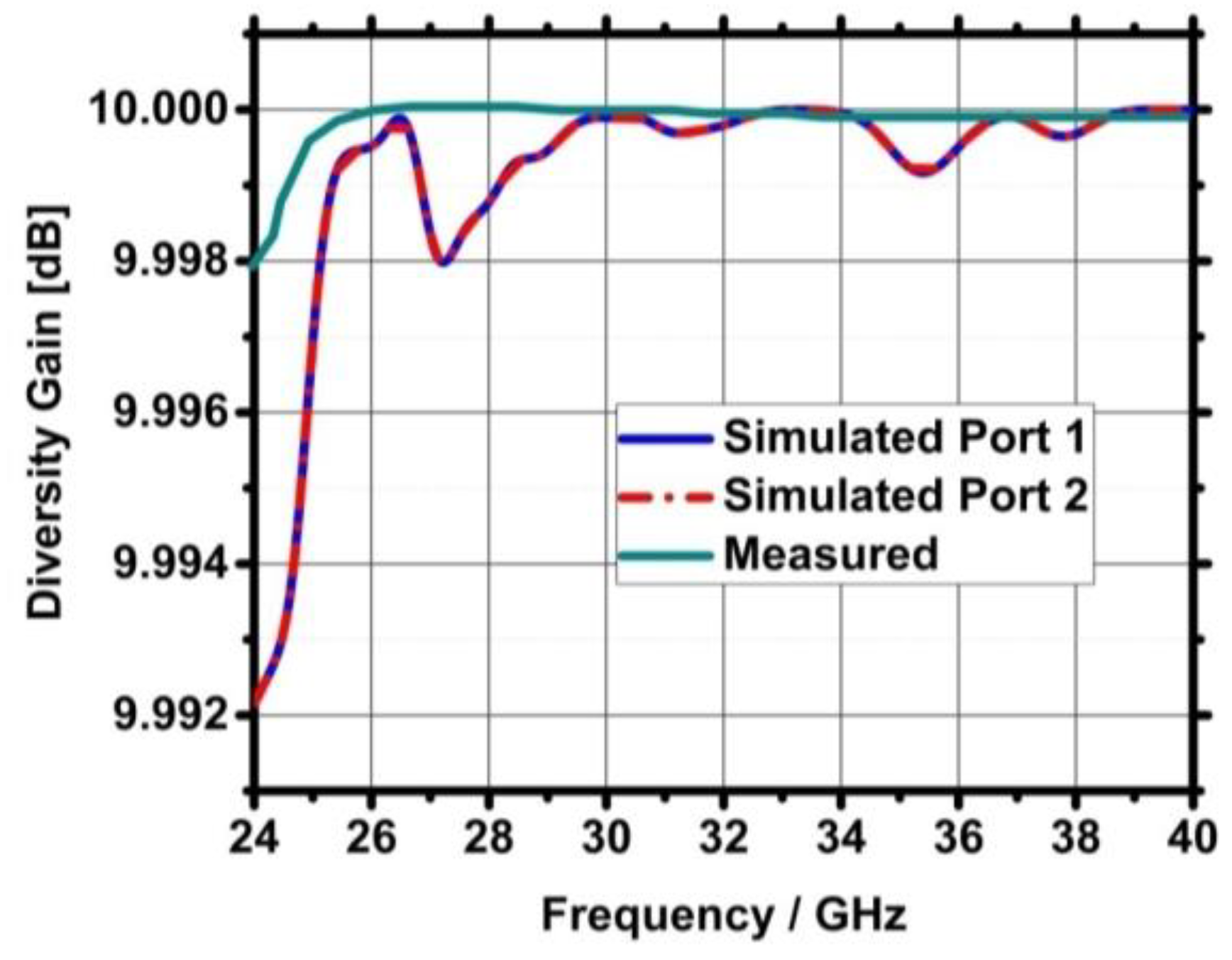
7.2. Diversity Gain
8. Conclusions
Author Contributions
Funding
Data Availability Statement
Conflicts of Interest
References
- Akpakwu, G.; Silva, B.; Hancke, G.; Mahfouz, A.A. A Survey on 5G Networks for the Internet of Things: Communication Technologies and Challenges. IEEE Access 2017, 5, 3619–3647. [Google Scholar] [CrossRef]
- Zhang, J.A.; Cheng, P.; Weily, A.; Guo, Y. Towards 5th generation cellular mobile networks. Aust. J. Telecommun. Digit. Econ. 2014, 2, 34. [Google Scholar] [CrossRef][Green Version]
- Guevara, L.; Cheein, F.A. The role of 5G technologies: Challenges in smart cities and intelligent transportation systems. Sustainability 2020, 12, 6469. [Google Scholar] [CrossRef]
- O’Connell, E.; Moore, D.; Newe, T. Challenges associated with implementing 5G in manufacturing. Telecom 2020, 1, 48–67. [Google Scholar] [CrossRef]
- Zikria, Y.B.; Kim, S.W.; Afzal, M.K.; Wang, H.; Rehmani, M.H. 5G mobile services and scenarios: Challenges and solutions. Sustainability 2018, 10, 3626. [Google Scholar] [CrossRef]
- Chávez-Santiago, R.; Szydełko, M.; Kliks, A. 5G: The Convergence of Wireless Communications. Wirel. Pers. Commun. 2015, 83, 1617–1642. [Google Scholar] [CrossRef]
- Tiwari, P.; Gahlaut, V.; Kaushik, M.; Rani, P.; Shastri, A.; Singh, B. Advancing 5G Connectivity: A Comprehensive Review of MIMO Antennas for 5G Applications. Int. J. Antennas Propag. 2023, 2023, 5906721. [Google Scholar] [CrossRef]
- Anguera, J.; Andújar, A.; Huynh, M.C.; Orlenius, C.; Picher, C.; Puente, C. Advances in antenna technology for wireless handheld devices. Int. J. Antennas Propag. 2013, 2013, 838364. [Google Scholar] [CrossRef]
- Tiwari, P.; Kaushik, M.; Shastri, A.; Gahlaut, V. Design of a MIMO Rectangular Dielectric Resonator Antenna for 5G Millimeter-Wave Communications. In Proceedings of the 2023 IEEE Wireless Antenna and Microwave Symposium (WAMS), Ahmedabad, India, 7–10 June 2023; pp. 1–6. [Google Scholar]
- Sunthari, P.M.; Veeramani, R. Multiband microstrip patch antenna for 5G wireless applications using MIMO techniques. In Proceedings of the 1st International Conference on Recent Advances in Aerospace Engineering (ICRAAE), Coimbatore, India, 3–4 March 2017; pp. 1–5. [Google Scholar]
- Tiwari, P.; Gahlaut, V.; Kaushik, M.; Shastri, A.; Siddiqui, G.; Singh, B. A High-Frequency Planar-Configured Millimeter-Wave MIMO Antenna for Fifth-Generation NR Operations. In International Journal of RF and Microwave Computer-Aided Engineering; Wiley: Hoboken, NJ, USA, 2023. [Google Scholar]
- Li, J.L.; Luo, M.H.; Liu, H. Design of a slot antenna for future 5G wireless communication systems. In Proceedings of the 2017 Progress Electromagnetics Research Symposium—Spring (PIERS), St Petersburg, Russia, 22–25 May 2017; pp. 739–741. [Google Scholar]
- Al-Saedi, H.; Attari, J.A.; Wahab, W.M.A.; Mittra, R.; Safavi-Naeini, S. Single-feed dual-band aperture-coupled antenna for 5G applications. In Proceedings of the 2018 18th International Symposium on Antenna Technology and Applied Electromagnetics (ANTEM), Waterloo, ON, Canada, 19–22 August 2018; pp. 1–2. [Google Scholar]
- Kammakattu, S.; Bora, P.; Mudaliar, M.; Dhanade, Y.; Madhav, B. Linear array Yagi-Uda 5G antenna for vehicular application. Int. J. Eng. Technol. 2017, 7, 513. [Google Scholar]
- Huang, C.-Y.; Cheng, J.-C. Millimeter-Wave Leaky-Wave Antenna for 5G Mobile Phone. In Proceedings of the 2020 International Workshop on Electromagnetics: Applications and Student Innovation Competition (iWEM), Penghu, Taiwan, 26–28 August 2020; pp. 1–2. [Google Scholar]
- González, R.M.; Márquez, R.T.R. Tri-Band Log-Periodic Microstrip Antenna Design (2.4, 5.5 and 3.6 GHz Bands) for Wireless Mobile Devices Application. In Proceedings of the International Congress of Telematics and Computing WITCOM, Puerto Vallarta, Mexico, 2–6 November 2020; pp. 18–29. [Google Scholar]
- Andrews, J.G.; Buzzi, S.; Choi, W.; Hanly, S.V.; Lozano, A.; Soong, A.C.K.; Zhang, J.C. What will 5G be? IEEE J. Sel. Areas Commun. 2014, 32, 1065–1082. [Google Scholar] [CrossRef]
- Shen, X.; Liu, Y.; Zhao, L.; Huang, G.; Shi, X.; Huang, Q. A miniaturized microstrip antenna array at 5G millimeter-wave band. IEEE Antennas Wirel. Propag. Lett. 2019, 18, 1671–1675. [Google Scholar] [CrossRef]
- Jilani, S.F.; Alomainy, A. Millimeter-wave T-shaped MIMO antenna with defected ground structures for 5G cellular networks. IET Microw. Antennas Propag. 2018, 12, 672–677. [Google Scholar] [CrossRef]
- Wei, K.; Zhang, Z.; Chen, W.; Feng, Z. A Novel Hybrid-Fed Patch Antenna with Pattern Diversity. IEEE Antennas Wirel. Propag. Lett. 2010, 9, 562–565. [Google Scholar] [CrossRef]
- Kaiser, T.; Feng, Z.; Dimitrov, E. An overview of ultra-wideband systems with MIMO. Proc. IEEE 2009, 97, 285–312. [Google Scholar] [CrossRef]
- Hong, W. Solving the 5G mobile antenna puzzle: Assessing future directions for the 5G mobile antenna paradigm shift. IEEE Microw. Mag. 2017, 18, 86–102. [Google Scholar] [CrossRef]
- Munir, M.E.; Kiani, S.H.; Savci, H.S.; Marey, M.; Khan, J.; Mostafa, H.; Parchin, N.O. A Four Element mm-Wave MIMO Antenna System with Wide-Band and High Isolation Characteristics for 5G Applications. Micromachines 2023, 14, 776. [Google Scholar] [CrossRef] [PubMed]
- Tiwari, P.; Kaushik, M.; Shastri, A.; Rai, J.; Gahlaut, V. Simulated Design and Analysis of Highly Isolated 5G Millimeter-Waves MIMO Antenna with Wideband Characteristic. In Proceedings of the International Conference on Microwave, Antenna and Communication (MAC) 2023, Allahabad, India, 24–26 March 2023. [Google Scholar]
- Sokunbi, O.; Kishk, A. Millimeter-Wave MIMO Antenna With Decoupling Structures for Isolation Enhancement. In Proceedings of the 2023 17th European Conference on Antennas and Propagation (EuCAP), Florence, Italy, 26–31 March 2023; pp. 1–4. [Google Scholar]
- Gaya, S.; Sokunbi, O.; Hamza, A.; Sheikh, S.I.M.; Attia, H. Multiple-input-multiple-output antenna with pattern reconfiguration and correlation reduction for WLAN applications. Eng. Rep. 2020, 2, e12272. [Google Scholar] [CrossRef]
- Sang, L.; Hu, Z.; Wu, S.; Huang, W.; Tu, H.; Wang, W.; Chen, P.; Hong, W. A Dual-Band Planar Antenna Array with High-Frequency Ratio for Both Sub-6 Band and mm-Waveband. IEEE Trans. Antennas Propag. 2023, 71, 3856–3867. [Google Scholar] [CrossRef]
- Tiwari, P.; Kaushik, M.; Shastri, A.; Gahlaut, V. Two Element Microstrip-Fed Slot Loaded Millimeter Wave MIMO Antenna. In Proceedings of the IEEE International Conference for Advancement in Technology (ICONAT), Goa, India, 24–26 January 2023; pp. 1–5. [Google Scholar]
- Cuneray, K.; Akcam, N.; Okan, T.; Arican, G.O. 28/38 GHz dual-band MIMO antenna with wideband and high gain properties for 5G applications. AEU-Int. J. Electron. Commun. 2023, 162, 154553. [Google Scholar] [CrossRef]
- Xie, M.; Wei, X.; Tang, Y.; Hu, D. A parasitic decoupling structure for dual-polarized patch antenna arrays. IEEE Antennas Wirel. Propag. Lett. 2023, 22, 1351–1355. [Google Scholar] [CrossRef]
- Arya, V.; Garg, T.; Al-Khafaji, H.M.R. High Gain and Wide-Angle Continuous Beam Scanning SIW Leaky-Wave Antenna. Electronics 2023, 12, 370. [Google Scholar] [CrossRef]
- Arya, V.; Garg, T.; Al-Khafaji, H.M.R. SIW Leaky Wave Antenna for THz Applications. Electronics 2023, 12, 1839. [Google Scholar] [CrossRef]
- Arya, V.; Garg, T. Leaky Wave Antenna: Past and Present. In Proceedings of Integrated Intelligence Enable Networks and Computing; Singh Mer, K.K., Semwal, V.B., Bijalwan, V., Crespo, R.G., Eds.; Algorithms for Intelligent Systems; Springer: Berlin/Heidelberg, Germany, 2021. [Google Scholar]
- Megahed, A.A.; Abdelhay, E.H.; Abdelazim, M.; Soliman, H.Y. 5G millimeter-wave wideband MIMO antenna arrays with high isolation. EURASIP J. Wirel. Commun. Netw. 2023, 2023, 61. [Google Scholar] [CrossRef]
- Zhang, Y.M.; Yao, M.; Zhang, S. Wide-Band Decoupled Millimeter-Wave Antenna Array for Massive MIMO Systems. IEEE Antennas Wirel. Propag. Lett. 2023, 37, 1258–1273. [Google Scholar] [CrossRef]
- Mistri, R.K.; Singh, A.K.; Mahto, S.K.; Sinha, R. Quad element millimetre-wave MIMO antenna for 5G communication. J. Electromagn. Waves Appl. 2023, 7, 1–23. [Google Scholar] [CrossRef]
- Khabba, A.; Amadid, J.; Mohapatra, S.; El Ouadi, Z.; Ahmad, S.; Ibnyaich, S.; Zeroual, A. UWB dual-port self-decoupled o-shaped monopole MIMO antenna with small-size easily extendable design and high diversity performance for millimeter-wave 5G applications. Appl. Phys. A 2022, 128, 725. [Google Scholar] [CrossRef]
- Al-Bawri, S.S.; Islam, M.T.; Shabbir, T.; Muhammad, G.; Islam, M.S.; Wong, H.Y. Hexagonal shaped near zero index (NZI) metamaterial-based MIMO antenna for millimeter-wave application. IEEE Access 2020, 8, 181003–181013. [Google Scholar] [CrossRef]
- Sehrai, D.A.; Abdullah, M.; Altaf, A.; Kiani, S.H.; Muhammad, F.; Tufail, M.; Irfan, M.; Glowacz, A.; Rahman, S. A Novel High Gain Wideband MIMO Antenna for 5G MillimeterWave Applications. Electronics 2020, 9, 1031–1043. [Google Scholar] [CrossRef]
- Khalid, M.; Naqvi, S.I.; Hussain, N.; Rahman, M.U.; Fawad Mirjavadi, S.S.; Khan, M.J.; Amin, Y. A 4-port MIMO antenna with defected ground structure for 5G millimeter wave applications. Electronics 2020, 9, 71–83. [Google Scholar] [CrossRef]
- Aggarwal, R.; Roy, A.; Kumar, G. Comparative Analysis of Different Dielectric Substrate for the Design of Millimeter Wave Microstrip Patch Antenna. In Computer Aided Constellation Management and Communication Satellites: Proceedings of the International Conference on Small Satellites, ICSS 2022 2023 Mar 1; Springer Nature: Singapore; pp. 93–104.
- Kumar, A.; Kumar, A.; Kumar, A. Defected Ground Structure Based High Gain, Wideband and High Diversity Performance Quad-Element MIMO Antenna Array for 5G Millimeter-Wave Communication. Prog. Electromagn. Res. B 2023, 101, 1–6. [Google Scholar] [CrossRef]
- Rani, P.; Tiwari, P.; Singh, T.; Gahlaut, V. A Compact Ground Fed UWB Antenna with Single Band Notch Characteristics. In Proceedings of the 2021 2nd International Conference on Smart Electronics and Communication (ICOSEC), Trichy, India, 7–9 October 2021; pp. 435–440. [Google Scholar]
- Ali, W.; Das, S.; Medkour, H.; Lakrit, S. Planar dual-band 27/39 GHz millimeter-wave MIMO antenna for 5G applications. Microsyst. Technol. 2021, 27, 283–292. [Google Scholar] [CrossRef]


| Ref. | Frequency (GHz) | Size | Number of Ports | Substrate Used | Technique | Bandwidth (GHz) | Isolation (dB) | ECC | DG (dB) |
|---|---|---|---|---|---|---|---|---|---|
| [37] | 24–34 | 11 × 20.5 | 2 | RT Duroid 5880 | Defected connected ground | 10 | >23.6 | <0.044 | >9.99 |
| [38] | 24–29.9 | 23 × 24 | 2 | RT Duroid 5880 | Metamaterial | 5.5 | >24 | <0.0013 | >9.9 |
| [39] | 23–40 | 80 × 80 | 4 | RT Duroid 5880 | Simple full ground | 16 | >10 | <0.0014 | >9.6 |
| [40] | 25.5–29.6 | 30 × 35 | 4 | Rogers R04350B | Defected ground | 4.1 | >17 | <0.001 | >9.99 |
| [41] | 27.5–40 | 18.2 × 4.1 | 2 | RT Duroid 5880 | Electromagnetic band gap (EBG) | 12.5 | >15 | Not provided | Not provided |
| [42] | 25.30–42 | 12 × 45.2 | 4 | RT Duroid 5880 | Defected ground | 16.7 | >24 | 0.0003 | 9.97 |
| [43] | 25.1–37.5 | 12 × 50.8 | 4 | RT Duroid 5880 | Defected ground | 12.4 | >22 | 0.005 | 9.9 |
| [34] | 27–40 | 55.25 × 27.635 | 2 | FR-4 | Decoupling structure | 13 | >30 | 0.00003 | 9.9994 |
| [44] | 26–42 | 26 × 11 | 2 | RT Duroid 5880 | Separate defected ground | 2.5, 6 | >25 | 0.16 | 9.986 |
| Presented work | 25–40 | 35 × 35 | 2 | RT Duroid 5880 | Decoupling and defected connected ground | 15 | >28.7 | 0.0016 | >9.992 |
| Ref. | Advantages | Demerits |
|---|---|---|
| [37] | Wide bandwidth (10 GHz), good isolation (>23.6 dB) | Moderate size |
| [38] | High isolation (>24 dB), metamaterial technique | Limited bandwidth, moderate size. |
| [39] | Good isolation | Lower isolation and ECC |
| [40] | Decent isolation (>17 dB), low ECC) | Limited bandwidth, moderate size. |
| [41] | Small size, wide bandwidth | Limited frequency range, low isolation no ECC or DG data provided |
| [42] | Wide bandwidth (16.7 GHz), high isolation (>24 dB) | Moderate size, 4 ports |
| [43] | Good isolation and reasonable bandwidth. | Moderate size, 4 ports |
| [34] | Very high isolation (>30 dB), low DG | Limited bandwidth, large size. |
| [44] | Large size, moderate isolation | Limited bandwidth |
| Proposed Work | Wide bandwidth (15 GHz), high isolation (>28.7 dB), low ECC and DG | Large size |
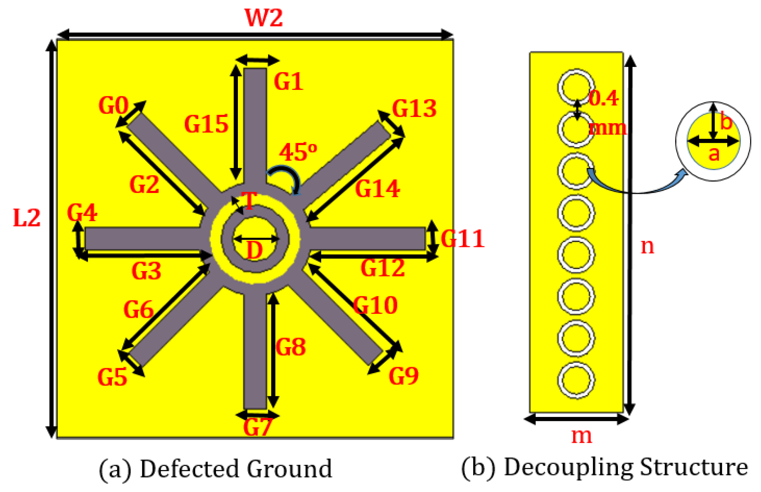
| Symbols | Dimensions (mm) | Symbols | Dimensions (mm) |
|---|---|---|---|
| L1 | 17.5 | Ri | 4.8 |
| W1 | 17.5 | Ro | 4.85 |
| L2 | 35 | B | 1.2 |
| W2 | 35 | A | 0.8 |
| Wa | 1.65 | M | 2.83 |
| Q1 | 3.25 | N | 13.33 |
| Q2 | 6.75 | G0=G5=G9=G13 | 1.27 |
| Q3 | 0.8 | G1=G4=G7=G11 | 1.8 |
| L1 | 4.80 | T | 1.5 |
| R1 | 3.3 | D(Diameter-inner circle) | 2 |
| R2 | 1.8 | H(Diameter-Outer circle) | 4.5 |
| r | 5.2 | G3=G8=G12=G15 | 11.13 |
| G2=G6=G10=G14 | 12.14 |
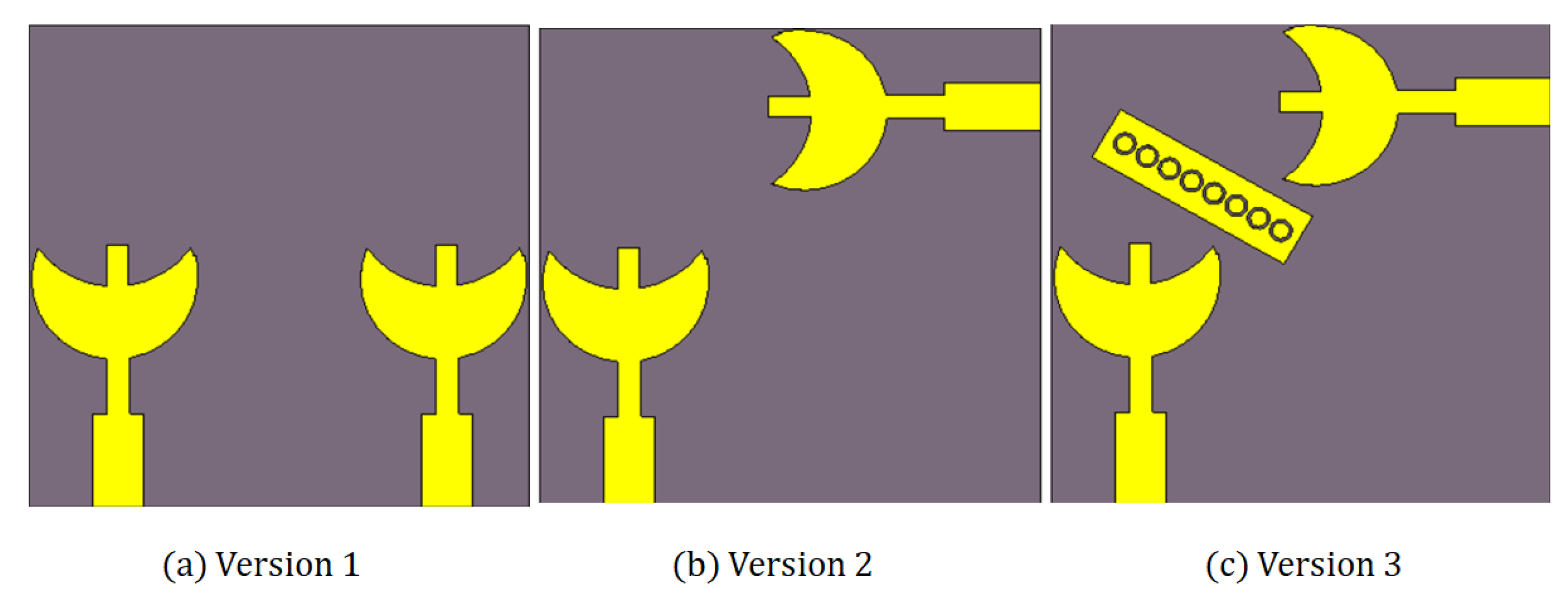
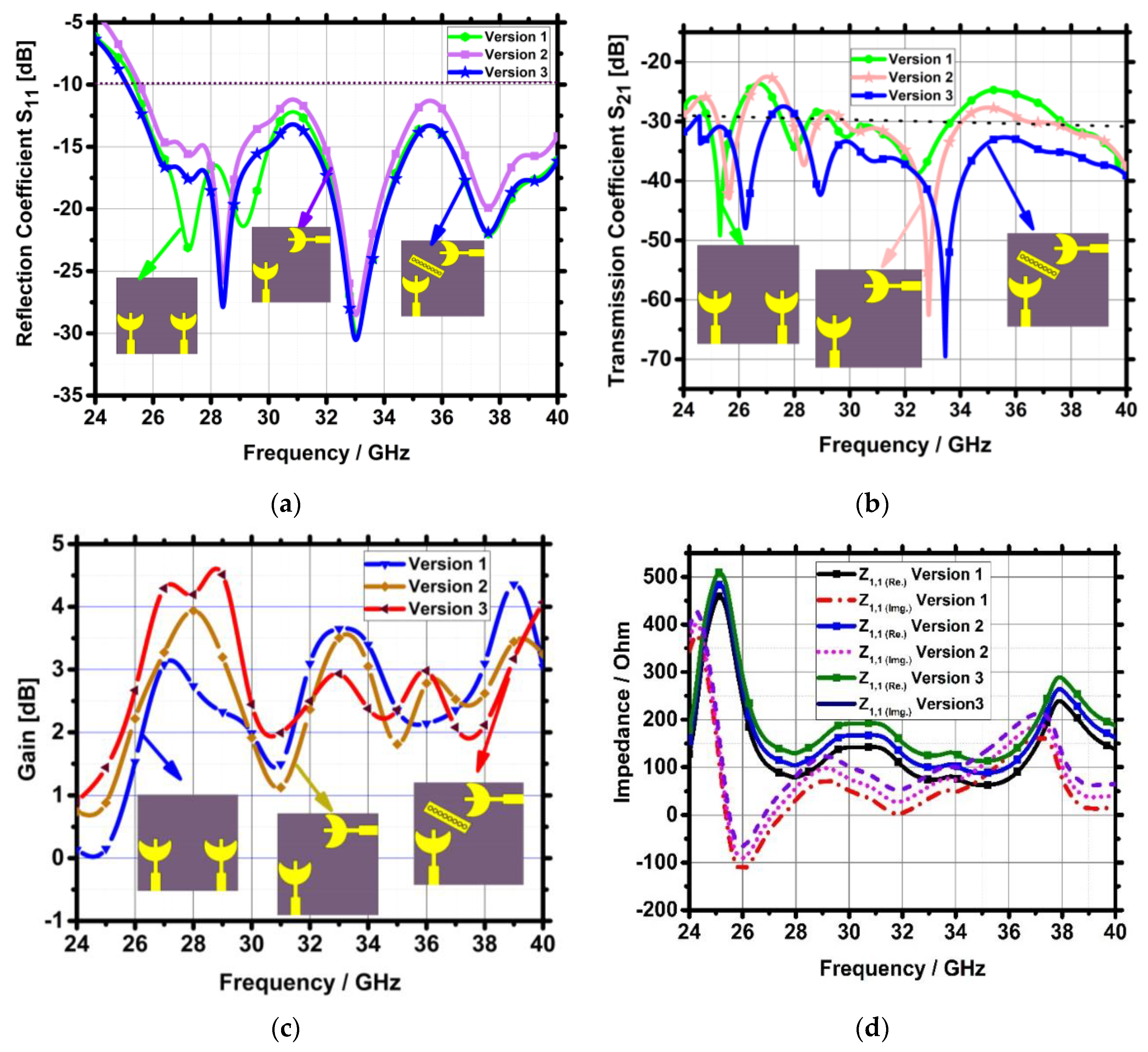
| Versions | ||S11|| | |S21| | Gain | |Z11| |
|---|---|---|---|---|
| Version 1 | <−10 dB from 25.3 to 40 GHz and 14.7 GHz bandwidth (PWB = 45.93%), minimum amplitude of −31.1 dB is obtained at 33 GHz. | >−23 dB | 4.3 dB | Nearly 50 Ω at 33 GHz |
| Version 2 | <−10 dB from 25.25 to 40 GHz and 14.75 GHz (PWB = 46.09%), minimum amplitude of −31.1 dB at 33 GHz. | >−23 dB | 3.5 dB | Nearly 50 Ω at 33 GHz |
| Version 3 | <−10 dB from 25 to 40 GHz, bandwidth of 15 GHz (PWB = 46.87%), minimum amplitude of −30.91 dB at 33 GHz. | >−28 dB | 4.6 dB | Nearly 50 Ω at 28.2 GHz a 33 GHz |
Disclaimer/Publisher’s Note: The statements, opinions and data contained in all publications are solely those of the individual author(s) and contributor(s) and not of MDPI and/or the editor(s). MDPI and/or the editor(s) disclaim responsibility for any injury to people or property resulting from any ideas, methods, instructions or products referred to in the content. |
© 2023 by the authors. Licensee MDPI, Basel, Switzerland. This article is an open access article distributed under the terms and conditions of the Creative Commons Attribution (CC BY) license (https://creativecommons.org/licenses/by/4.0/).
Share and Cite
Tiwari, P.; Gahlaut, V.; Kaushik, M.; Shastri, A.; Arya, V.; Elfergani, I.; Zebiri, C.; Rodriguez, J. Enhancing Performance of Millimeter Wave MIMO Antenna with a Decoupling and Common Defected Ground Approach. Technologies 2023, 11, 142. https://doi.org/10.3390/technologies11050142
Tiwari P, Gahlaut V, Kaushik M, Shastri A, Arya V, Elfergani I, Zebiri C, Rodriguez J. Enhancing Performance of Millimeter Wave MIMO Antenna with a Decoupling and Common Defected Ground Approach. Technologies. 2023; 11(5):142. https://doi.org/10.3390/technologies11050142
Chicago/Turabian StyleTiwari, Poonam, Vishant Gahlaut, Meenu Kaushik, Anshuman Shastri, Vivek Arya, Issa Elfergani, Chemseddine Zebiri, and Jonathan Rodriguez. 2023. "Enhancing Performance of Millimeter Wave MIMO Antenna with a Decoupling and Common Defected Ground Approach" Technologies 11, no. 5: 142. https://doi.org/10.3390/technologies11050142
APA StyleTiwari, P., Gahlaut, V., Kaushik, M., Shastri, A., Arya, V., Elfergani, I., Zebiri, C., & Rodriguez, J. (2023). Enhancing Performance of Millimeter Wave MIMO Antenna with a Decoupling and Common Defected Ground Approach. Technologies, 11(5), 142. https://doi.org/10.3390/technologies11050142