Article

Tool Wear Characteristics and Strengthening Method of the Disc Cutter for Nomex Honeycomb Composites Machining with Ultrasonic Assistance

1
Division of Advanced Manufacturing, Shenzhen International Graduate School, Tsinghua University, Shenzhen 518055, China
2
School of Mechanical and Automotive Engineering, Xiamen University of Technology, Xiamen 361024, China
3
Xiamen Golden Egret Special Alloy Co., Ltd., Xiamen 361006, China
4
Shenzhen Tsingding Technology Co., Ltd., Shenzhen 518133, China
5
Department of Mechanical Engineering, Tsinghua University, Beijing 100084, China
*
Authors to whom correspondence should be addressed.
Technologies 2022, 10(6), 132; https://doi.org/10.3390/technologies10060132
Submission received: 19 November 2022 / Revised: 13 December 2022 / Accepted: 14 December 2022 / Published: 16 December 2022
(This article belongs to the Section Manufacturing Technology)

Abstract

:
Nomex honeycomb composites are used extensively in aerospace, automotive, and other industries due to their superior material properties. However, the tool wear during their machining can compromise the processing accuracy and the stability of the whole machining process, thus studies on the tool wear and strengthening method are urgently needed. This study presents a radial difference calculation method (RDC) to evaluate the tool wear of the disc cutter quantitatively in both conventional cutting and ultrasonic assisted cutting. The morphology of the tool wear process and its characteristics were analyzed. Two different heat treatments (salt bath quenching and vacuum quenching) were carried out to strengthen the tool performance. The research results demonstrated that ultrasonic vibration could significantly reduce the tool wear of the disc cutter, by up to 36%, after the same machining time. Salt bath quenching and vacuum quenching can both strengthen the tool performance. Particularly, after vacuum quenching treatment, the disc cutter’s metallographic grains were refined, and the tool wear could be reduced by 64%, compared to the as-received disc cutter. The findings in this study could be instructive to obtain further understanding of the machining mechanism and to improve methods in ultrasonic assisted cutting of Nomex honeycomb composites.

1. Introduction

Nomex honeycomb composites are a type of biomimetic material composed of phenolic resin and aramid fiber. They have low density, high specific strength and specific stiffness, corrosion resistance, excellent environmental adaptability, outstanding electrical insulation and impact resistance [1,2,3], etc. Therefore, they are widely used in aerospace, automobile, shipbuilding, construction, and other fields [4,5]. Due to their porous thin-walled structure, Nomex honeycomb composites are susceptible to burrs, tearing, collapse, and other problems during the traditional high-speed milling process. The cutting tool wears out rapidly and the quality of the machined surface is poor. The milling process produces much dust, which dramatically pollutes the workplace and jeopardizes the workers’ health [6,7].
Substantial research has focused attention on ultrasonic assisted machining (UAM) technology to address these issues. Numerous studies demonstrated that UAM has significant advantages in reducing cutting force, improving cutting tool wear and machining quality [8,9,10], etc. This technology shows many excellent properties in machining processes of different composites [11,12,13,14]. Ultrasonic assisted cutting is one of the ultrasonic assisted machining technologies. Ultrasonic vibration is applied on the cutting tool to facilitate material removal, reduce cutting force and material deformation simultaneously. Straight-blade knives and disc cutters are the two types of cutting tools for machining Nomex honeycomb composites. The disc cutter is generally used in the finishing machining process so the state of the disc cutter has a significant influence on the vibration performance, machining accuracy, and machining efficiency of the whole ultrasonic machining system [15,16,17].
The majority of current research on Nomex honeycomb material machining by the disc cutter focuses on its structural design and processing characteristics [18,19,20,21], etc. For example, Xia et al. [18] optimized the structure of the disc cutter. They studied the change regularity of the stiffness with geometric parameters and optimized the process parameters by finite element simulations and experiments. The results showed that the tool wedge angle and the outer diameter significantly influenced the process. While the spindle speed and ultrasonic amplitude were negatively connected with the cutting force, the cutting force was positively correlated with the feed speed, cutting width, and cutting depth. Ahmad et al. [19] designed a new saw-tooth disc cutter and studied different structural parameters of the new disc cutter on resonance frequency by finite element simulations and experiments. The results demonstrated that the ultrasonic frequency and amplitude of cutting tools were sufficient for the ultrasonic machining of Nomex honeycomb composites. However, there are few studies on the tool wear performance and strengthening methods of the disc cutter. Jaafar et al. [22,23] found that the disc cutter had two types of tool wear when cutting Nomex honeycomb composites: edge-chipping and resin material adhesion. The width of damage on the cutting edge of the disc cutter was used as the measurement criterion for the tool wear. There are currently no accepted criteria for the tool wear of the disc cutter, and it is still in the exploratory phase. Researchers usually establish the criteria according to experimental conditions, such as the width of the cutting-edge damage, the width of the material adhesion, and so on. David et al. [24] studied the machining process of honeycomb core materials by a saw-tooth disc cutter through high-speed photography. The results showed that the tool wore out rapidly, and the materials easily collapsed, leading to more severe tool wear and more cutting heat. The tool wear speed far exceeded expectations. Thus, it is essential to improve the tool performance as there is no specific strengthening method for the disc cutter. Heat treatment is a commonly used method to improve the tool performance [25,26]. However, the proper method to improve the performance of the disc cutter used in ultrasonic assisted cutting of Nomex honeycomb composites still needs to be explored. The tool life and the surface quality of the workpiece can be improved significantly if the appropriate strengthening method is adopted to improve the tool wear resistance.
In order to deeply study the tool wear of the disc cutter in ultrasonic assisted cutting of Nomex honeycomb composites, this study proposes a radial difference calculation method to evaluate the tool wear quantitatively. The morphology of the tool wear process and its characteristics were analyzed through experiments of considerable cutting length (more than 500 m). Two different heat treatments (salt bath quenching and vacuum quenching) were applied to strengthen the tool performance.

2. Experimental Details

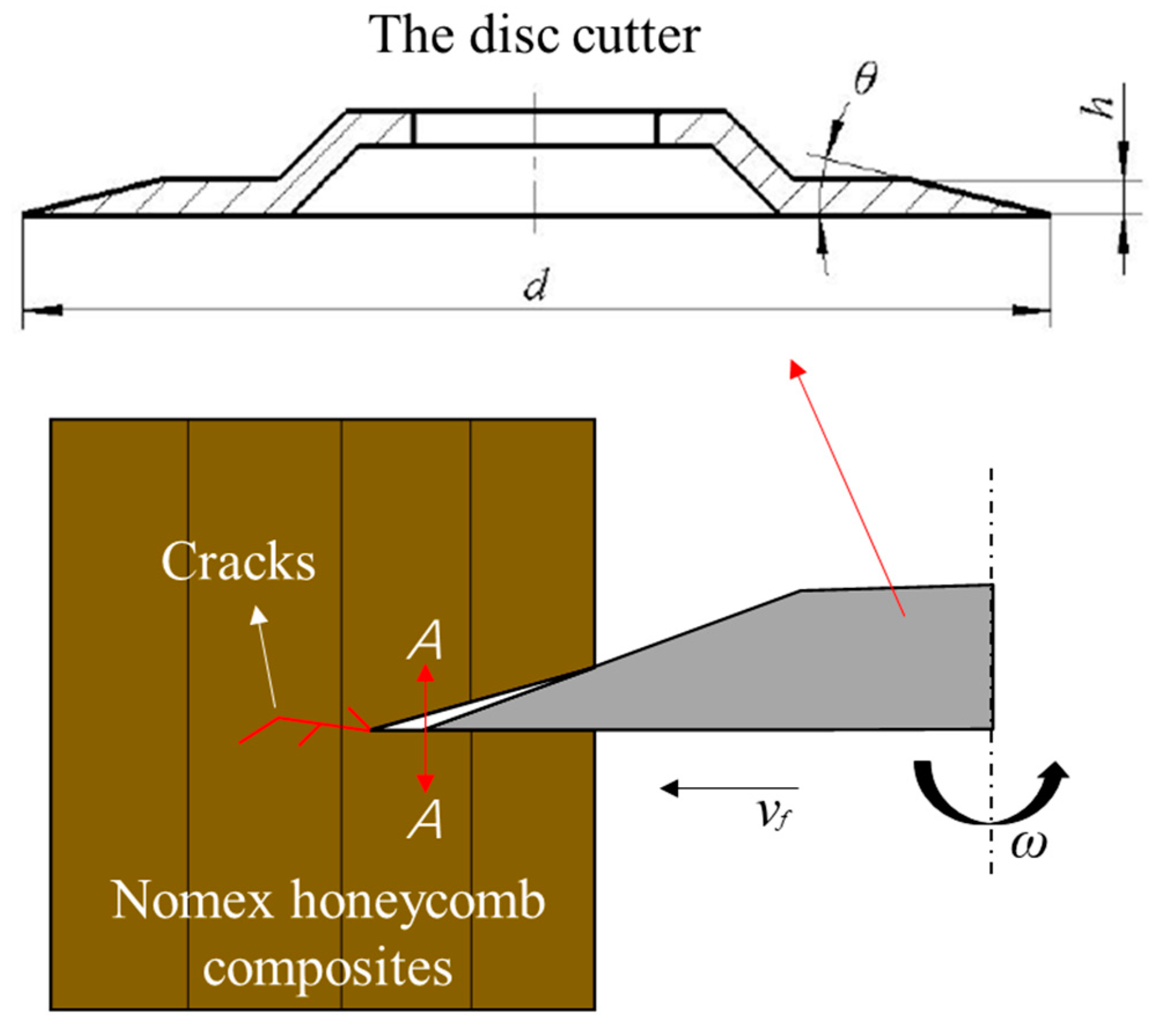
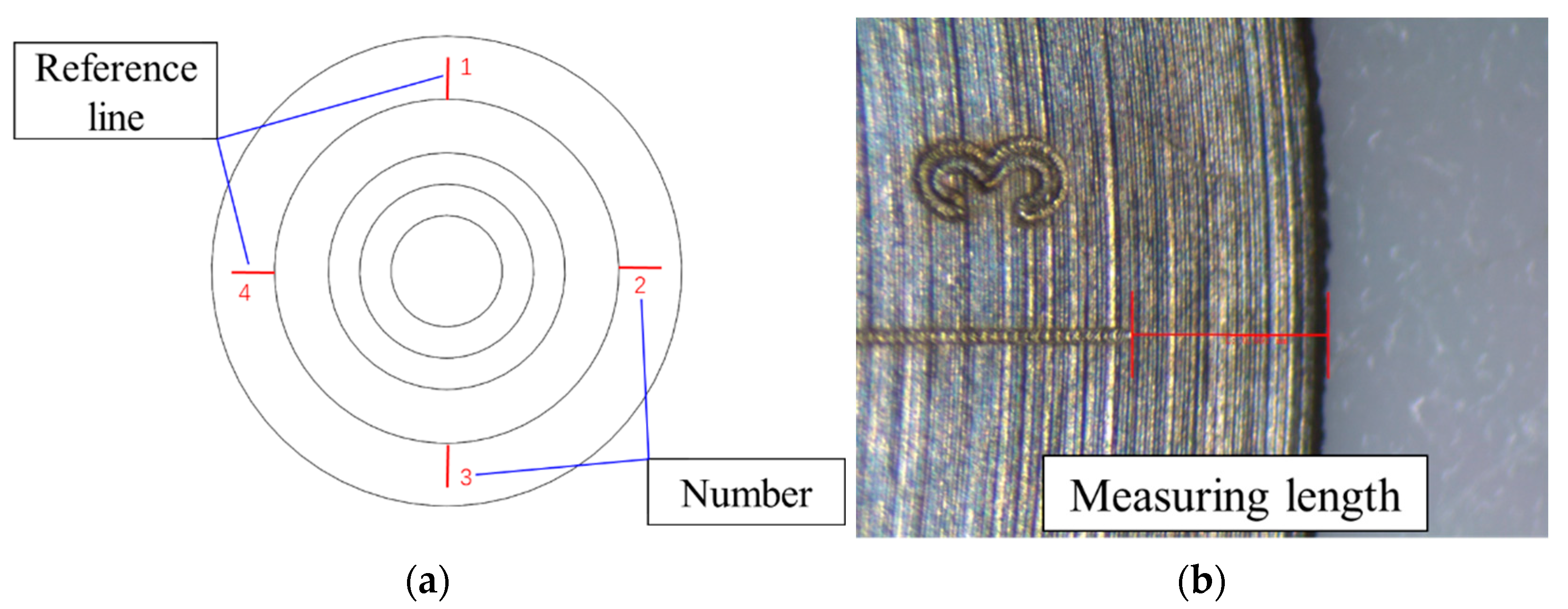
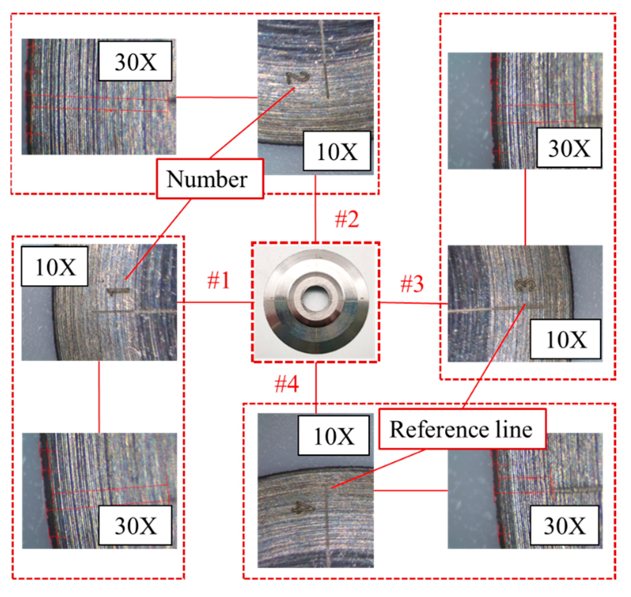
2.1. Evaluation Method for Tool Wear Characteristics

The typical structure of the disc cutter and the schematic diagram of its machining process are shown in Figure 1. The disc cutter rotates at a high speed and, at the same time, vibrates with an ultrasonic frequency in the axial direction. The states of the disc cutter before and after machining are shown in Figure 2. It can be seen that the cutting edge of the disc cutter is the area that is susceptible to wear. The structure of the disc cutter makes it challenging to assess the tool wear by using conventional criteria, such as the flank wear width.
To evaluate the tool wear of the disc cutter quantitatively, this study proposes a radial difference calculation method, which involves calculating the difference of tool diameter before and after wear. To realize this method, laser etching was used to mark the disc cutter in a total of four locations at 90° intervals, as shown in Figure 3. A reference line and a number were etched on each position. The end of the reference line was used as the measurement point. The laser etching platform and the etching process are shown in Figure 4.
As shown in Figure 5, when observing the tool wear, the number is first found by microscope at a low magnification, and then the line is found at a high magnification as a reference to observe the tool wear. The distance between the edge of the disc cutter and the end of the reference line is measured. Finally, the radial difference is calculated as the value of the tool wear. This method is called the radial difference calculation method (RDC). During the experiments, the tool wear at set intervals was observed and the radial difference recorded so as to explore the rule of conduct of the tool wear.

2.2. Tool Strengthening Method

Two different heat treatments (salt bath quenching and vacuum quenching) were applied to strengthen the tool performance in this study. The processing parameters, listed in Table 1, were those used for high-speed tool steel, which is the material of the disc cutter. The cooling medium was the molten salt and the vacuum, respectively.
The heat treatment consisted of three steps: preheating, quenching, and tempering. First, the disc cutter was preheated to 850 °C, and then the temperature was raised to 1200 °C. After that, the disc cutter was cooled in the molten salt or in the vacuum environment. Finally, the tempering was conducted three times. The only difference between the two heat treatments was the cooling medium. The vacuum furnace was used in place of the salt bath furnace in the vacuum quenching process to realize the vacuum environment. Vacuum quenching can avoid oxidation, decarburization, and deformation on the surface of workpieces. The disadvantages of the vacuum quenching method are large equipment investment and low processing efficiency.
After the heat treatment, the hardness of the disc cutter was measured by an automatic Rockwell hardness tester (SCTMC-560 RSSZ). Two cutters were tested for each heat treatment and each cutter was tested for five points. The metallographic specimens of the disc cutter were prepared and the metallographic structure was observed by a metallographic microscope.

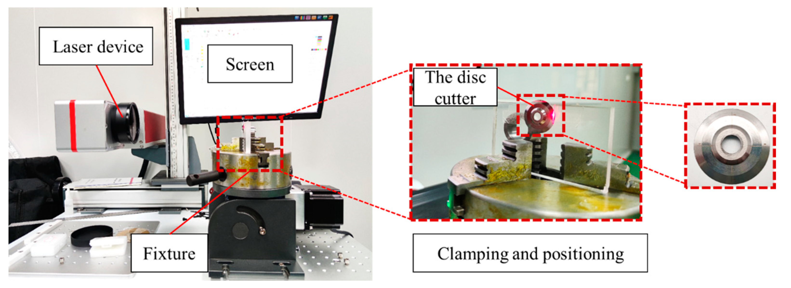
2.3. Experimental Setup

The wear experiments were conducted on a self-developed experimental platform. This experimental platform consisted of a 5-axis machining center (DU810, EUMA), a self-designed ultrasonic assisted cutting system, microscope, computer, dynamometer, laser displacement sensor, Nomex honeycomb composites workpiece, and fixture, as shown in Figure 6.
The self-designed ultrasonic assisted cutting system comprised an ultrasonic controller, an ultrasonic assisted cutting tool handle, and the disc cutter. This cutting system could work continuously for more than 12 h. The output power of the ultrasonic controller was 1000 W and its output frequency was 18~35 kHz. The microscope was employed to observe and measure the tool wear. The laser displacement sensor was used to measure the ultrasonic amplitude of the disc cutter. The experimental parameters are shown in Table 2.
As there are currently no accepted criteria for the tool wear of the disc cutter, the tool wear was evaluated by the radial difference calculation method, proposed in Section 2.1, at set intervals (set cutting length), based on engineering experience. According to the size of the workpiece and cutting parameters, the cutting length of the disc cutter was 4.31 m after removing each layer of the workpiece. To observe and record the whole tool wear process, the observation interval was short at the beginning of the cutting process, and it gradually became longer as the experiments proceeded. The arrangement of tool wear observation is shown in Table 3.

3. Results and Discussion

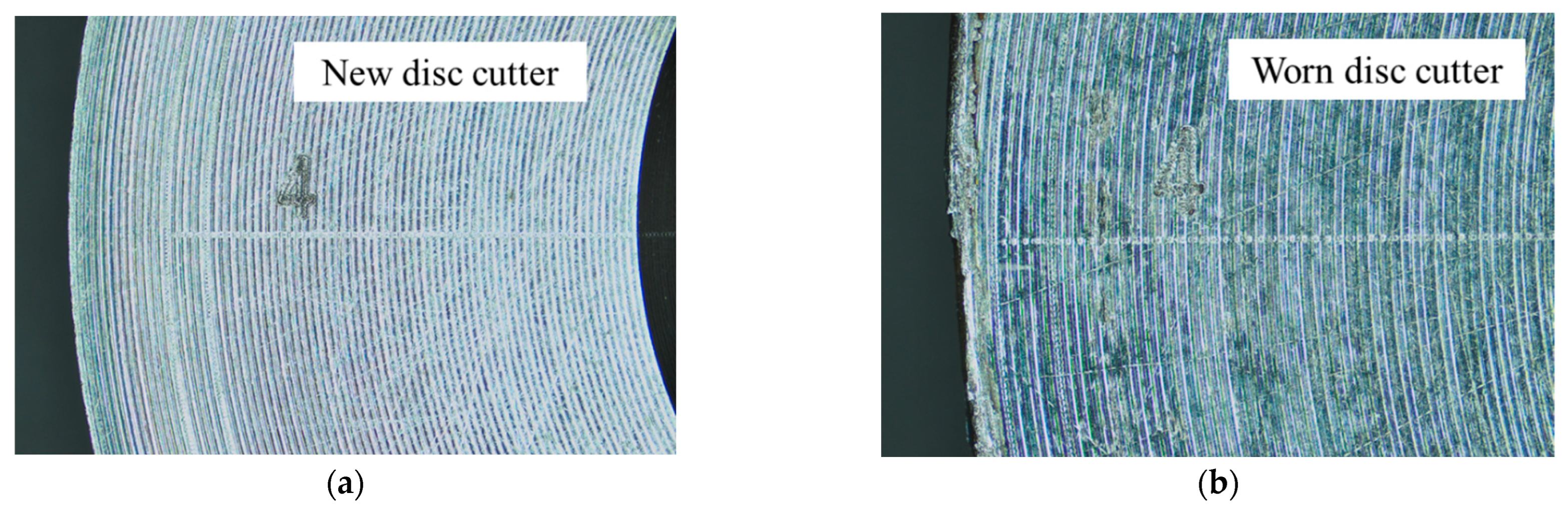
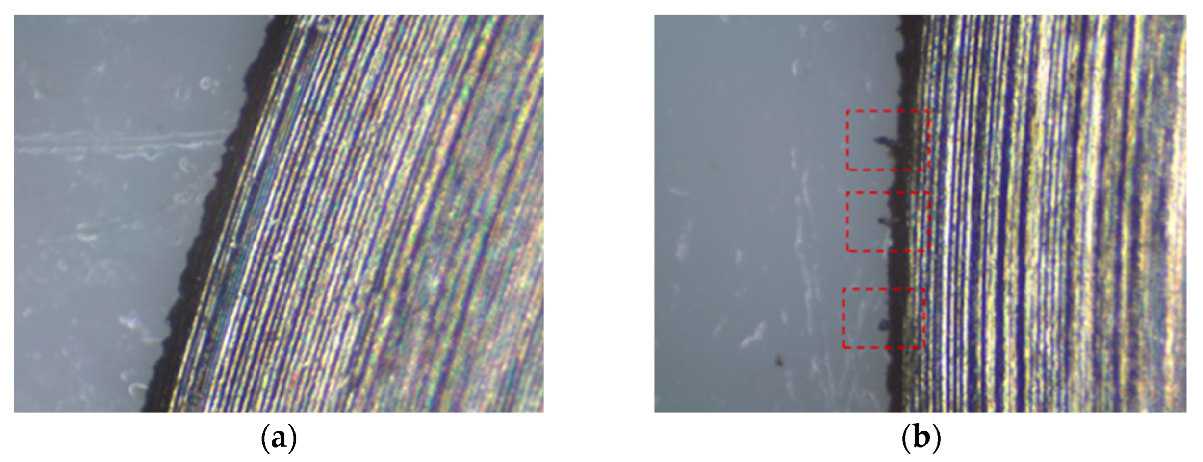
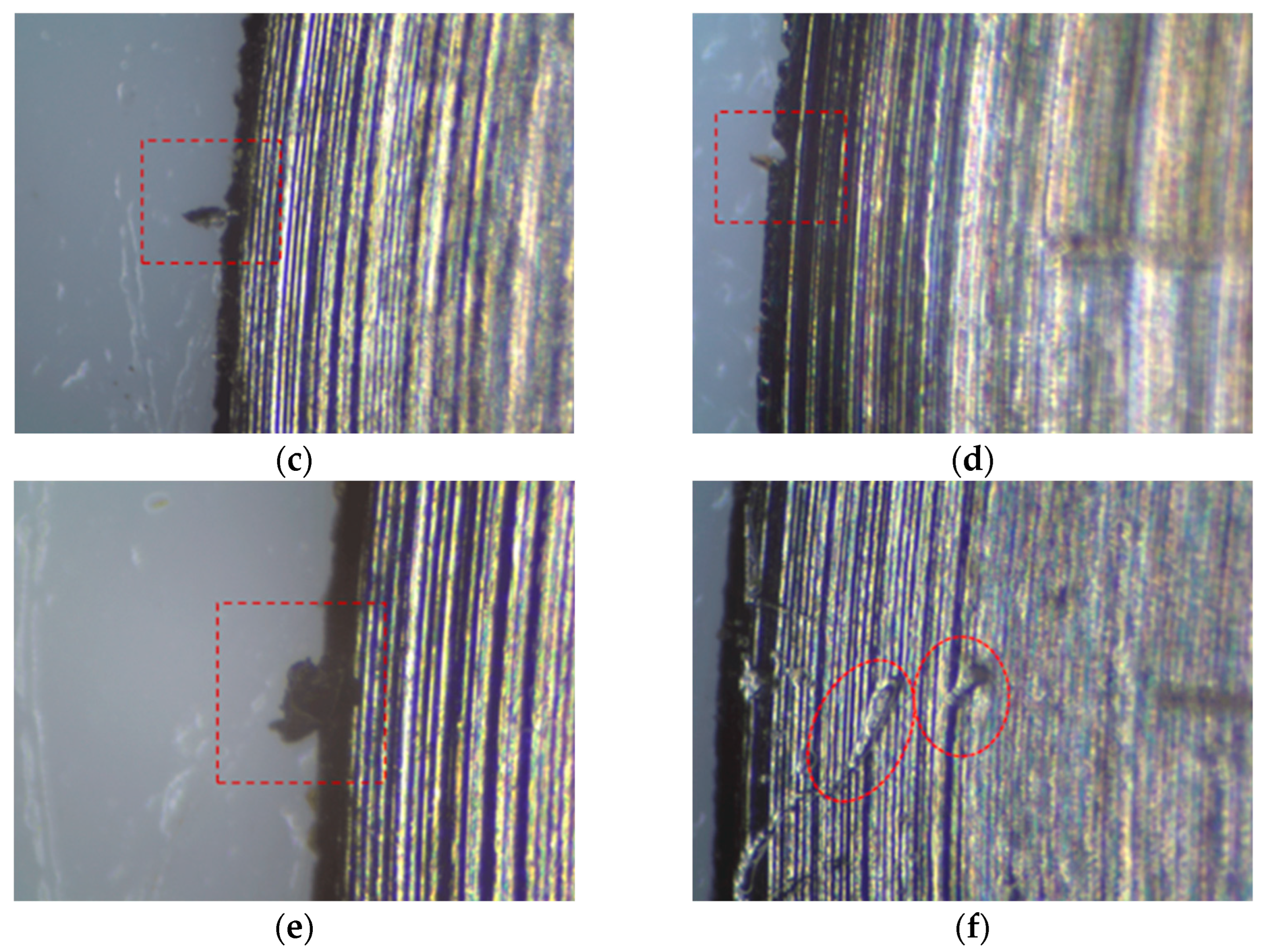
3.1. The Morphology of Tool Wear Process

Figure 7 demonstrates how the cutting edge of the disc cutter changed during the machining process. The cutting edge was intact before machining. As machining proceeded, small tears started to emerge on the cutting edge when the cutting length reached 2.87 m, and the maximum length of tears did not exceed 81 μm. When the cutting length reached 34.44 m, the tears increased up to 150 μm in length. Edge chipping occurred when the cutting length reached 51.66 m, with a width of 76 μm and depth of 55 μm. The cutting edge curled after machining 413.28 m and scratches showed on the surface of the disc cutter after machining 515.04 m. The length of scratches could reach 436 μm. It is reasonable to speculate that these scratches were caused by the edge chippings from the disc cutter itself as the material of the Nomex honeycomb composites was not hard enough to cause the damage.
It can be seen that the cutting process went smoothly at the beginning with small tears as typical morphology of the tool wear. With increase in the cutting length, the state of the cutting edge deteriorated. Edge chipping and curls happened more often. Moreover, the surface of the disc cutter was damaged at the end stage of the cutting process.

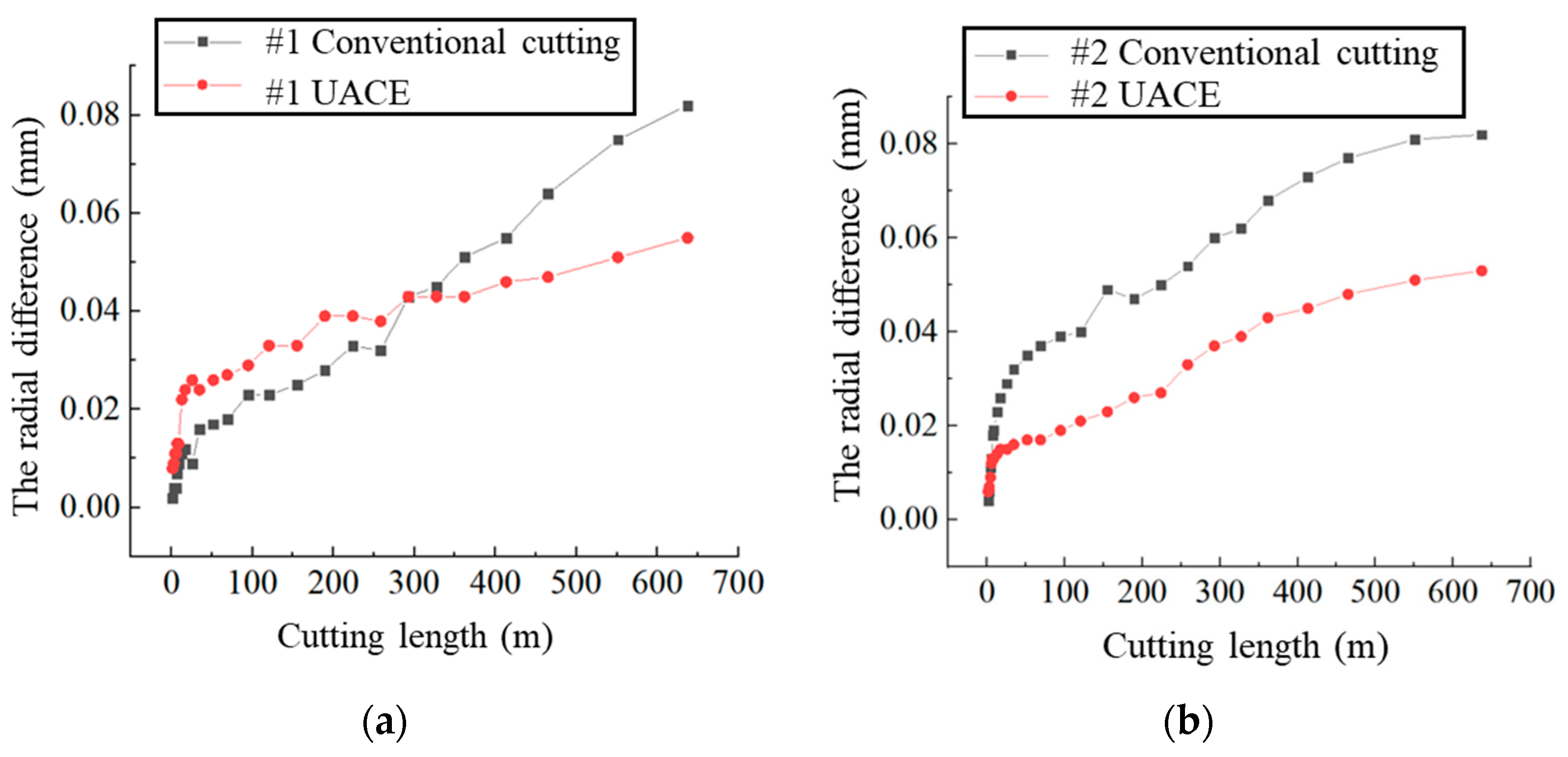
3.2. The Analysis of Tool Wear

The radial difference of the disc cutter was recorded to evaluate the tool wear quantitatively. Figure 8 shows the changes in the radial difference at 4 different positions which were marked by laser etching, respectively. It can be seen that at the beginning of the cutting process (from 0~50 m), the radial difference of the disc cutter increased rapidly and there was a rapid wear period, both in conventional cutting experiments and ultrasonic assisted cutting experiments (UACE), although the value in UACE on position 1 was larger than that in traditional cutting experiments. Then, a stable wear period followed. In this period, the radial difference of the disc cutter in UACE was much smaller than that in conventional cutting experiments.
Considering that there were deviations in the measurement at different positions, the mean value of these 4 positions was taken to comprehensively evaluate the regularity of the tool wear, as shown in Figure 9. There was a rapid wear period and a stable wear period in the two kinds of experiments. The results in UACE were better than those in the conventional cutting experiments. Taking the final value as the reference, it could be ascertained that ultrasonic vibration could significantly reduce the tool wear of the disc cutter, reaching 36% after the same machining time.

3.3. The Tool Wear of the Strengthened Disc Cutter

Hardness and uniformity can be used to characterize the wear resistance of the cutting tool. It can be seen from Figure 10 that the average hardness of disc cutters quenched in a vacuum was HRA 83.17, and that of disc cutters quenched in a salt bath was HRA 83.22. The values were consistent. However, the standard deviation of the data from the vacuum quenching treatment was 0.17, while it was 0.33 from the salt bath quenching treatment. The hardness distribution of the disc cutters after vacuum quenching treatment was more uniform.
The metallographic structure of disc cutters is shown in Figure 11. The shape of the grain was the same under a 500-fold magnification, and consisted of tempered martensite, residual austenite, and carbide. It can be seen that the grains under vacuum quenching were refined to a certain extent, and their dispersion degree was better. The distribution of carbides in the metallographic structure by vacuum quenching treatment was more uniform than that by salt bath quenching treatment.
The average radial difference of the disc cutter under vacuum quenching treatment was recorded by using the same experimental method mentioned in Section 2, as shown in Figure 12. The disc cutter under vacuum quenching treatment in UACE entered the stable wear period quickly and this reduced the tool wear of the disc cutter by up to 64%, compared to conventional cutting experiments, if the final value was taken as the reference. It could be observed that the vacuum quenching treatment could significantly improve the tool wear performance of the disc cutter in machining Nomex honeycomb composites.

4. Conclusions

Tool wear occurs easily during the machining of Nomex honeycomb composites with a disc cutter, which affects the processing accuracy and the stability of the entire machining process. Both conventional cutting experiments and UACE were carried out on a self-developed experimental platform. Two different heat treatments (salt bath quenching and vacuum quenching) were carried out to strengthen the tool performance. The conclusions can be summarized as follows:
(1)
An evaluation method was proposed to evaluate the tool wear of the disc cutter quantitatively which was called the radial difference calculation method. Small tears were typical morphology of the tool wear at the beginning of the machining process. Edge chipping and curls occurred with increase of the cutting length. Furthermore, even the surface of the disc cutter was damaged at the end stage of the cutting process.
(2)
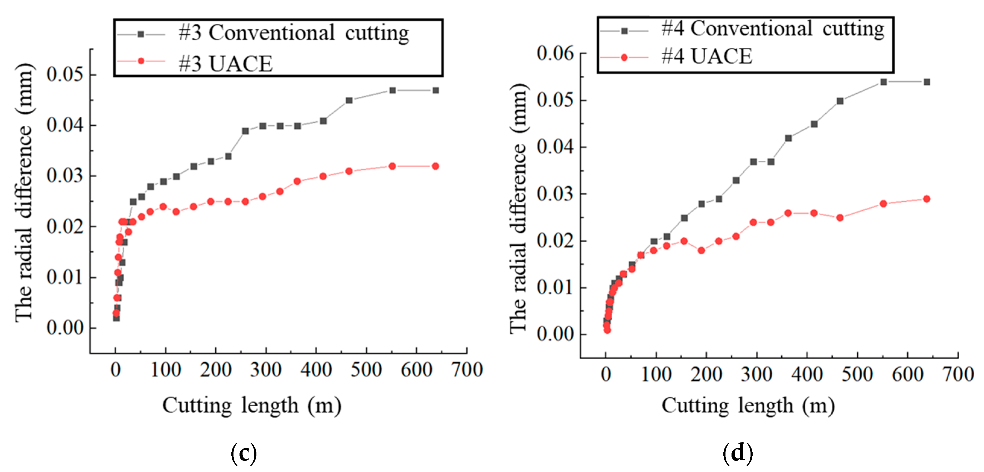
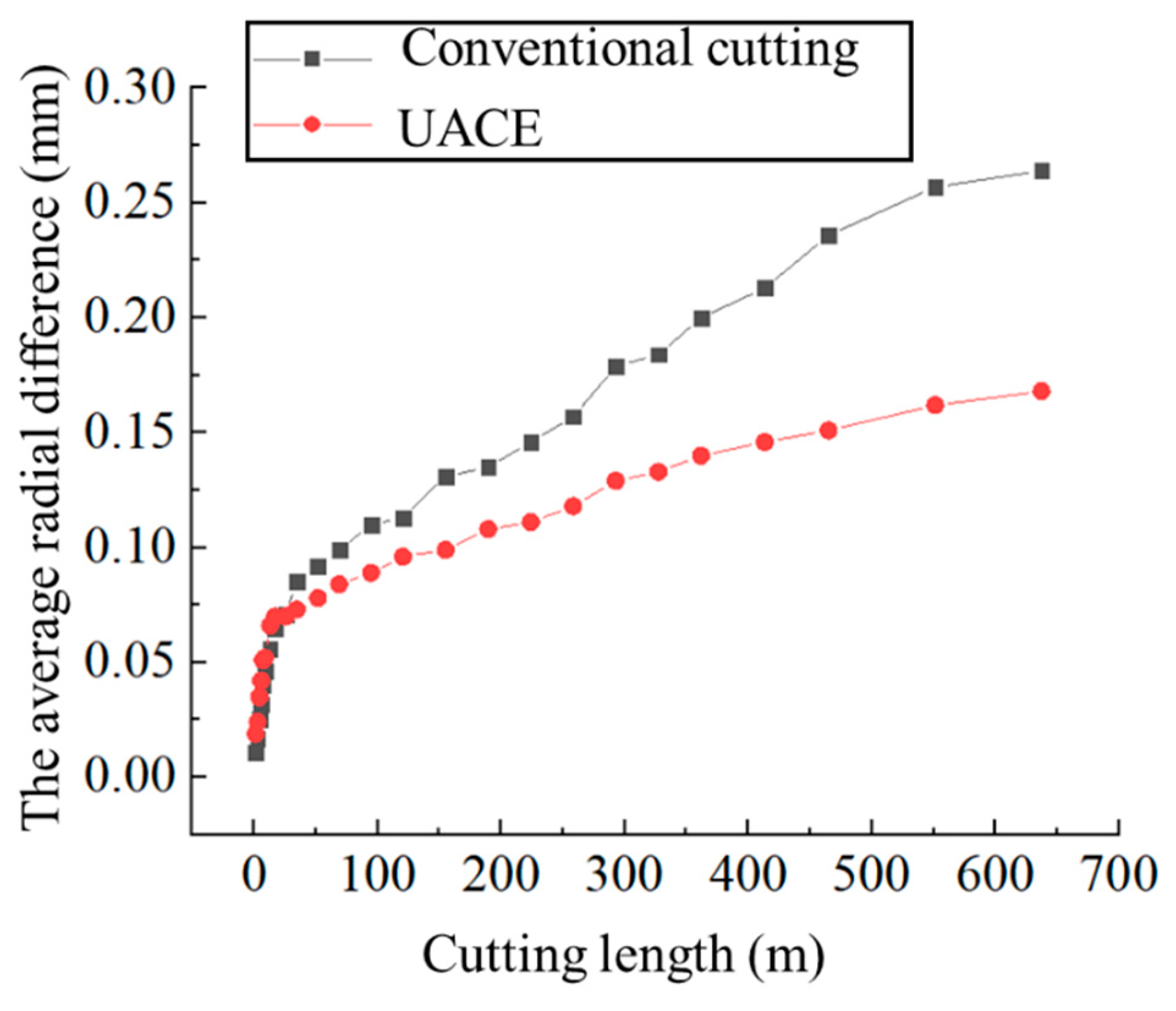
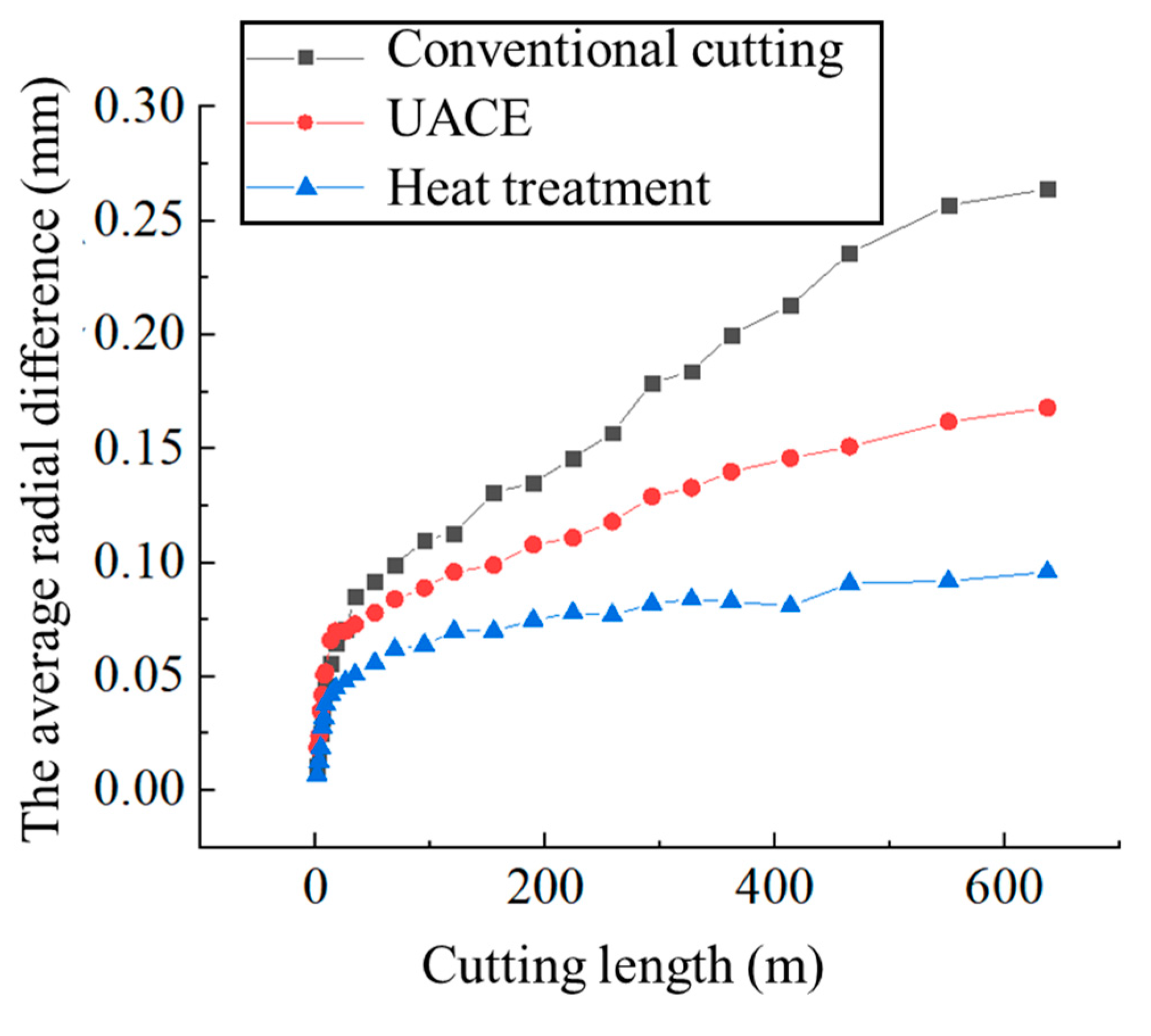
There was a rapid wear period and a stable wear period during the tool wear process. In the stable wear period, the radial difference of the disc cutter in UACE was significantly smaller than that in conventional cutting experiments. The ultrasonic vibration could significantly reduce the tool wear of the disc cutter by up to 36% after the same machining time.
(3)
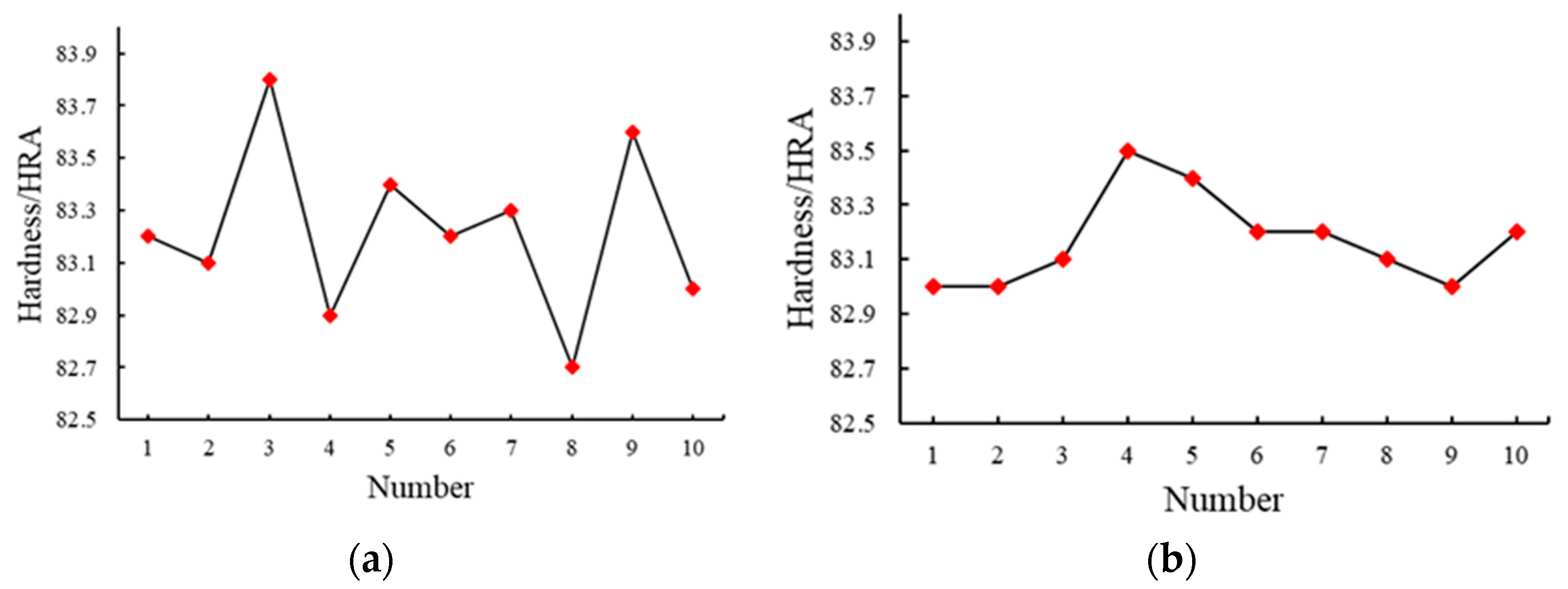
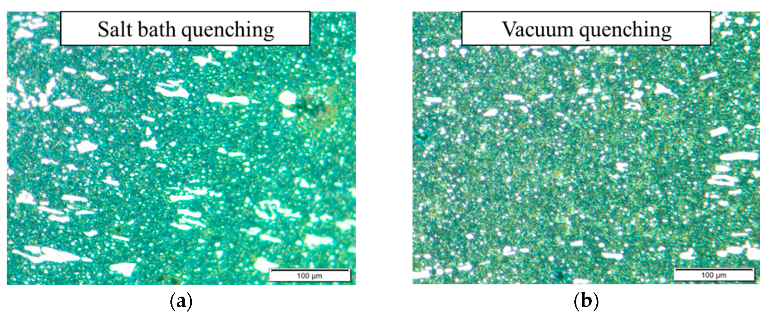
Vacuum quenching could significantly improve the wear resistance of the disc cutter. By changing the salt bath quenching to vacuum quenching in the heat treatment process, the metallographic grains were refined and their distribution became more uniform. The tool wear of the disc cutter after vacuum quenching treatment in UACE could be reduced up to 64%, compared to conventional cutting experiments if the final value was taken as the reference.

Author Contributions

Conceptualization, H.Z. and W.S.; methodology, P.F. and F.F.; validation, J.X. and F.F.; investigation, W.S., J.X. and E.J.; resources, F.F., Y.M. and C.X.; writing—original draft preparation, H.Z., J.X. and H.K.; writing—review and editing, H.K., J.X. and F.F.; supervision, P.F.; funding acquisition, P.F., F.F. and H.Z. All authors have read and agreed to the published version of the manuscript.

Funding

This research was funded by the National Key Research and Development Program under Grant No. 2019YFB1704800, the Shenzhen Foundational Research Project (General program) under Grant No. JCYJ20190813173607172, the Natural Science Foundation of Fujian Province under Grant No. 2022J05280 and the Scientific Research Start-up Project of Xiamen University of Technology under Grant No. YKJ22015R.

Institutional Review Board Statement

Not applicable.

Informed Consent Statement

Not applicable.

Data Availability Statement

The data presented in this study are available from the corresponding author with a reasonable request.

Conflicts of Interest

The authors declare no conflict of interest.

References

  1. Foo, C.C.; Chai, G.B.; Seah, L.K. Mechanical properties of Nomex material and Nomex honeycomb structure. Compos. Struct. 2007, 80, 588–594. [Google Scholar] [CrossRef]
  2. Roy, R.; Nguyen, K.H.; Park, Y.B.; Kweon, J.H.; Choi, J.H. Testing and modeling of Nomex™ honeycomb sandwich Panels with bolt insert. Compos. Part B Eng. 2014, 56, 762–769. [Google Scholar] [CrossRef]
  3. Zhou, H.; Xu, P.; Xie, S.; Feng, Z.; Wang, D. Mechanical performance and energy absorption properties of structures combining two Nomex honeycombs. Compos. Struct. 2018, 185, 524–536. [Google Scholar] [CrossRef]
  4. Castanie, B.; Bouvet, C.; Ginot, M. Review of composite sandwich structure in aeronautic applications. Compos. Part C Open Access 2020, 1, 100004. [Google Scholar] [CrossRef]
  5. Ahmad, S.; Zhang, J.; Feng, P.; Yu, D.; Wu, Z.; Ke, M. Processing technologies for Nomex honeycomb composites (NHCs): A critical review. Compos. Struct. 2020, 250, 112545. [Google Scholar] [CrossRef]
  6. Han, S.-W.; Kim, H.-J. Experimental Study on Shape Machining Characteristics of Composite Honeycomb Core. J. Korean Soc. Manuf. Process Eng. 2014, 13, 28–35. [Google Scholar] [CrossRef]
  7. Jaafar, M.; Atlati, S.; Makich, H.; Nouari, M.; Moufki, A.; Julliere, B. A 3D FE Modeling of Machining Process of Nomex® Honeycomb Core: Influence of the Cell Structure Behaviour and Specific Tool Geometry. Procedia CIRP 2017, 58, 505–510. [Google Scholar] [CrossRef]
  8. Singh, R.P.; Singhal, S. Rotary Ultrasonic Machining: A Review. Mater. Manuf. Process. 2016, 31, 1795–1824. [Google Scholar] [CrossRef]
  9. Yang, Z.; Zhu, L.; Zhang, G.; Ni, C.; Lin, B. Review of ultrasonic vibration-assisted machining in advanced materials. Int. J. Mach. Tools Manuf. 2020, 156, 103594. [Google Scholar] [CrossRef]
  10. Xu, W.-X.; Zhang, L.-C. Ultrasonic vibration-assisted machining: Principle, design and application. Adv. Manuf. 2015, 3, 173–192. [Google Scholar] [CrossRef]
  11. Ning, F.D.; Cong, W.L.; Pei, Z.J.; Treadwell, C. Rotary ultrasonic machining of CFRP: A comparison with grinding. Ultrasonics 2016, 66, 125–132. [Google Scholar] [CrossRef] [Green Version]
  12. Zha, H.; Feng, P.; Zhang, J.; Yu, D.; Wu, Z. Material removal mechanism in rotary ultrasonic machining of high-volume fraction SiCp/Al composites. Int. J. Adv. Manuf. Technol. 2018, 97, 2099–2109. [Google Scholar] [CrossRef]
  13. Xu, J.; Feng, P.; Feng, F.; Zha, H.; Liang, G. Subsurface damage and burr improvements of aramid fiber reinforced plastics by using longitudinal–torsional ultrasonic vibration milling. J. Mater. Process. Technol. 2021, 297, 117265. [Google Scholar] [CrossRef]
  14. Feng, P.; Wang, J.; Zhang, J.; Zheng, J. Drilling induced tearing defects in rotary ultrasonic machining of C/SiC composites. Ceram. Int. 2017, 43, 791–799. [Google Scholar] [CrossRef]
  15. Wang, Y.; Kang, R.; Dong, Z.; Wang, X.; Huo, D.; Zhang, X. A Novel Method of Blade-Inclined Ultrasonic Cutting Nomex Honeycomb Core With Straight Blade. J. Manuf. Sci. Eng. 2021, 143, 041012. [Google Scholar] [CrossRef]
  16. Nath, C.; Rahman, M. Effect of machining parameters in ultrasonic vibration cutting. Int. J. Mach. Tools Manuf. 2008, 48, 965–974. [Google Scholar] [CrossRef]
  17. Ke, M.; Jianfu, Z.; Pingfa, F.; Zhijun, W.; Dingwen, Y.; Ahmad, S. Design and implementation of a mini ultrasonic cutting system for nomex honeycomb composites. In Proceedings of the 2019 16th International Bhurban Conference on Applied Sciences and Technology (IBCAST), Islamabad, Pakistan, 8–12 January 2019; pp. 148–152. [Google Scholar]
  18. Xia, Y.; Zhang, J.; Wu, Z.; Feng, P.; Yu, D. Study on the design of cutting disc in ultrasonic-assisted machining of honeycomb composites. In IOP Conference Series: Materials Science and Engineering; IOP Publishing: Bristol, UK, 2019; p. 012032. [Google Scholar]
  19. Ahmad, S.; Zhang, J.; Feng, P.; Yu, D.; Wu, Z.; Ke, M. Research on design and FE simulations of novel ultrasonic circular saw blade (UCSB) cutting tools for rotary ultrasonic machining of nomex honeycomb composites. In Proceedings of the 2019 16th International Bhurban Conference on Applied Sciences and Technology (IBCAST), Islamabad, Pakistan, 8–12 January 2019; pp. 113–119. [Google Scholar]
  20. Ahmad, S.; Zhang, J.; Feng, P.; Yu, D.; Wu, Z. Experimental study on rotary ultrasonic machining (RUM) characteristics of Nomex honeycomb composites (NHCs) by circular knife cutting tools. J. Manuf. Process. 2020, 58, 524–535. [Google Scholar] [CrossRef]
  21. Cao, W.; Zha, J.; Chen, Y. Cutting Force Prediction and Experiment Verification of Paper Honeycomb Materials by Ultrasonic Vibration-Assisted Machining. Appl. Sci. 2020, 10, 4676. [Google Scholar] [CrossRef]
  22. Jaafar, M.; Nouari, M.; Makich, H.; Moufki, A. 3D numerical modeling and experimental validation of machining Nomex® honeycomb materials. Int. J. Adv. Manuf. Technol. 2021, 115, 2853–2872. [Google Scholar] [CrossRef]
  23. Jaafar, M.; Makich, H.; Nouari, M. A new criterion to evaluate the machined surface quality of the Nomex® honeycomb materials. J. Manuf. Process. 2021, 69, 567–582. [Google Scholar] [CrossRef]
  24. Gill, D.D.; Yip-Hoi, D.M.; Meaker, M.; Boni, T.; Eggeman, E.L.; Brennan, A.M.; Anderson, A. Studying the mechanisms of high rates of tool wear in the machining of aramid honeycomb composites. In Proceedings of the International Manufacturing Science and Engineering Conference, Los Angeles, CA, USA, 4–8 June 2017; p. V002T003A002. [Google Scholar]
  25. Luthfiyah, S.; Faridh, A.; Soegijono, B. The Effect of Vacuum Quenching on Corrosion and Hardness of the Surface of SKD61 Steel. In IOP Conference Series: Materials Science and Engineering; IOP Publishing: Bristol, UK, 2019; p. 012033. [Google Scholar]
  26. Akao, T.; Sakurai, Y.; Onda, T.; Uehara, K.; Chen, Z.-C. Surface Modification of Cold-working Die Steel by Electron Beam Irradiation—Formation of Cemented Carbide Composite Layer. Procedia Eng. 2014, 81, 1939–1944. [Google Scholar] [CrossRef]
Figure 1. The schematic diagram of the disc cutter and its machining process.
Technologies 10 00132 g001
Figure 2. (a) A new disc cutter; (b) A worn disc cutter.
Technologies 10 00132 g002
Figure 3. (a) Four places at 90° intervals; (b) Marks by laser etching.
Technologies 10 00132 g003
Figure 4. The laser etching platform.
Technologies 10 00132 g004
Figure 5. The wear observation method of the disc cutter.
Technologies 10 00132 g005
Figure 6. The experimental platform.
Technologies 10 00132 g006
Figure 7. The morphology of tool wear: (a) Intact cutting edge; (b) Small tears (the cutting length reached 2.87 m); (c) Large tears (the cutting length reached 34.44 m); (d) Edge chipping (the cutting length reached 51.66 m); (e) Curls (the cutting length reached 413.28 m); (f) Scratches (the cutting length reached 515.04 m).
Technologies 10 00132 g007aTechnologies 10 00132 g007b
Figure 8. The radial difference of the disc cutter: (a) Position 1; (b) Position 2; (c) Position 3; (d) Position 4.
Technologies 10 00132 g008aTechnologies 10 00132 g008b
Figure 9. The average radial difference of the disc cutter in conventional cutting experiments and UACE.
Technologies 10 00132 g009
Figure 10. The hardness of the disc cutter after the heat treatment: (a) Salt bath quenching; (b) Vacuum quenching.
Technologies 10 00132 g010
Figure 11. The metallographic structure of the disc cutter after the heat treatment: (a) Salt bath quenching; (b) Vacuum quenching.
Technologies 10 00132 g011
Figure 12. The average radial difference of different disc cutters.
Technologies 10 00132 g012
Table 1. The processing parameters of two heat treatments.
PreheatingQuenchingTempering
Temperature
/°C
Heating Coefficient
/(s/mm)
Temperature
/°C
Heating Coefficient
/(s/mm)
Cooling MediumTemperature
/°C
850241180~120012~15500~600 °C
salt bath
550 °C × 1 h,
3 times
500~600 °C
vacuum
Table 2. The experimental parameters.
Conventional Cutting ExperimentsUltrasonic Assisted Cutting Experiments
The size of workpiece205 × 105 × 100 mm
The material of the disc cutterhigh speed steel (W6Mo5Cr4V2)
The size of the disc cutterwedge angle: 14°
outer diameter: 27 mm
thickness: 0.9 mm
Cutting parametersspindle speed: 3000 r/min
feed rate: 5000 mm/min
cutting width: 5 mm
cutting depth: 2 mm
Ultrasonic parameters/frequency: 19,825 Hz
amplitude: 20 μm
Table 3. The arrangement of tool wear observation.
Observing SequenceCutting LayerCutting Length
/m
Observing SequenceCutting LayerCutting Length
/m
10.331.431428120.54
20.672.871536154.98
314.311644189.42
41.335.741752223.86
51.677.171860258.30
628.611968292.74
7312.922076327.18
8417.222184361.62
9625.832296413.28
10834.4423108464.94
111251.6624128551.04
121668.8825148637.14
132294.71
Publisher’s Note: MDPI stays neutral with regard to jurisdictional claims in published maps and institutional affiliations.

