Article

A Machine-Learning-Based Approach to Critical Geometrical Feature Identification and Segmentation in Additive Manufacturing

1
Institute of Machine Tools and Manufacturing, ETH Zurich, CH-8092 Zurich, Switzerland
2
Inspire, Innovation Centre for Additive Manufacturing Switzerland (ICAMS), CH-9014 St. Gallen, Switzerland
3
Department of Computer Science, ETH Zurich, CH-8092 Zurich, Switzerland
*
Author to whom correspondence should be addressed.
Technologies 2022, 10(5), 102; https://doi.org/10.3390/technologies10050102
Submission received: 23 May 2022 / Revised: 31 August 2022 / Accepted: 13 September 2022 / Published: 16 September 2022
(This article belongs to the Special Issue Advanced Processing Technologies of Innovative Materials)

Abstract

:
Additive manufacturing (AM) processes offer a good opportunity to manufacture three- dimensional objects using various materials. However, many of the processes, notably laser Powder bed fusion, face limitations in manufacturing specific geometrical features due to their physical constraints, such as the thermal conductivity of the surrounding medium, the internal stresses, and the warpage or weight of the part being manufactured. This work investigates the opportunity to use machine learning algorithms in order to identify hard-to-manufacture geometrical features. The segmentation of these features from the main body of the part permits the application of different manufacturing strategies to improve the overall manufacturability. After selecting features that are particularly problematic during laser powder bed fusion using stainless steel, an algorithm is trained using simple geometries, which permits the identification of hard-to-manufacture features on new parts with a success rate of 88%, showing the potential of this approach.

1. Introduction

Laser powder bed fusion has shown great potential to change the way metallic parts are produced, allowing a freedom in part design not achievable with conventional manufacturing. However, the process requires supporting structures in overhanging areas, and the user must follow certain strict design guidelines to successfully manufacture the final complex component. Such guidelines were presented by Klahn et al. [1] on function-driven modeling and by Leutenecker-Twelsiek et al. [2] on the requirements to be considered when designing for AM. In this respect, Calignano [3] presented guidelines for support optimization for both aluminum and titanium alloys, representing an additional manual step in the build preparation process, requiring know-how in the whole AM process chain.
The current state-of-the-art commercial machines support a wide variety of processing parameters and scanning strategies. However, the selected set of manufacturing parameters will be applied with no distinction to all layers during the manufacturing process, and to all geometrical features. Hence, a productive parameter set (i.e., with a high energy input) could be used for its obvious advantages. This kind of parameter set will nevertheless display difficulties in resolving fine details such as lattice structures, and will cause severe degradation in overhanging areas, even with the use of contour scans, as shown by Staub et al. [4].
This is mainly due to the low thermal conductivity of the surrounding powder within the powder bed, as supported by the experiments involving process monitoring and simulation presented by Dursun et al. [5]. However, different parameter sets, even if suboptimal for the manufacturing of the whole part, could be beneficial to reduce the use of supporting structures, improve the surface quality, and allow lower overhanging angles with respect to the build plate. Notably, Chen et al. [6] showed through simulations using the finite volume method and experimental results the opportunity to improve the overhanging surface quality by tuning the scanning parameters. Ultimately, such process improvements could improve the productivity of the process, and more generally of the process chain, as the removal of the supporting structure is a costly task in several AM processes, including LPBF. Hence, there is a necessity to allow for parameter modification within certain features of a 3D model.
So far, the different commercial solutions for the preparation of build jobs do not offer the option to freely allocate specific manufacturing strategies to individual 3D part features. Even though some basic geometries have been identified, such as overhang, this does not allow the segmentation of the part or the tailoring of manufacturing parameters at these specific locations. The efforts made by Siemens towards a path optimizer [7] led to improved surface quality on a single demonstrator, yet this is far from being a standard tool. The application of core–shell strategies, as presented by Niendorf et al. [8], is not considered sufficient, as some features require specific scanning strategies considering not only the type of a feature, but also its orientation regarding the build direction, its thickness, or its volume. On the other hand, other commercial solutions such as Aconity3D GmbH (Germany) rely on a completely open architecture and allow the user to modify every single vector of the scanning path for each layer. This is also not satisfying for the treatment of large 3D files, as the tailoring of the scanning path should be done by taking the 3D geometry into account rather than single layers, one after the other. The recent work by Chen et al. [9] highlighted the efficiency of a part-specific scanning strategy by showing reductions in residual stresses due to the optimized scanning path.
Druzgalski et al. [10] highlighted the necessity of software that pre-corrects build files by adapting the process parameters. The authors proposed the extraction of features based on the sliced data, by analyzing scanning vectors, extracting risky vectors, and adapting parameters to these vectors and the 3 subsequent layers. This tailoring is supported by previous process monitoring data and a database of pre-simulated scanning strategies.
Shi et al. [11] proposed an approach for a manufacturability analysis and feature identification based on the heat kernel signature. This approach considers the loss of heat over time of a known source, e.g., the geometry to be manufactured, completely independently of the AM process. This method can describe the shapes and topological characteristics of a feature through its heat diffusion potential. The work showed promising results yet did not elaborate on the necessary time for computing the heat kernel signatures on complex geometries.
Finally, the literature presents an extensive overview of possible methods of process parameter tuning for the improvement of specific critical features but lacks scientific inputs on the recognition and segmentation of these feature from a complete part. The aim of this work is to identify specific features, segment them from the original geometry, and allow for an automated treatment for further parametrization in the build processor. The developed method can take into account complex 3D geometries based on the STL file standard. Throughout this work, the part orientation is considered as fixed from the beginning. The output is a set of different features, which altogether represent the part to be manufactured. This heuristic approach focuses on LPBF-critical features but can be used for the improvement of any AM process.

2. Materials and Methods

2.1. Features Definition

Specific scanning strategies to improve the part quality for specific features have been successfully tested, notably in early the work by Clijsters [12], where the first scanning adaptation strategies were successfully implemented to manufacture free-overhanging structure with limited down-face surface degradation. In the most recent work by Illies [
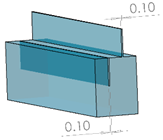
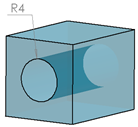
13], a thermal process simulation showed potential process parameter modifications to improve the quality of critical features. The lack of opportunity to recognize and segment the features from the core geometries has led these studies to become dead ends. To demonstrate the use of a novel approach for feature recognition and segmentation, different critical features must be defined, such as those proposed by Wegener et al. [14] and described in Table 1. The last column of Table 1 presents the parameter ranges in which the geometry is allowed to be modified for the machine learning approach presented in the following section. The criterion for criticality is defined for a standard grade of steel used in LPBF (e.g., SS316L, 17-4PH, maraging steel 300). Outside of the parameter range defined here, the features are either not critical or require a supporting structure, as an adaptation of the scanning strategy will not be enough to overcome the manufacturing difficulty. Even though this work is centered on limitations encountered while manufacturing steel in LPBF, it could be transferred to other metals and materials easily, as well as other processes, such as direct metal deposition. In such cases, the range of each feature, as well as its criterion for criticality, will need to be adapted.

2.2. Suitable Approaches for 3D Feature Identification

For the detection of critical features, multiple methods can be applied. However, the focus of this work is on identifying the 3D features in the 3D geometry and reducing the computational resources needed to a minimum. Hence, layer-by-layer approaches, double slicing, and the like are eliminated due to their high complexity and excessive computing time.
As most of the geometries used in AM are mostly available in the STL file format (i.e., a surface description of the 3D part, discretized with triangles), classifying triangles as critical in the triangle mesh by only taking the triangle-normal into account could be an option. However, complex parts are composed of thousands to millions of triangles and cannot be handled properly. Such approaches will result in successful results for overhanging structures but will not allow the identification of more complex features, such as fine walls and helix tubes, as they deliver no information on the overall geometry and the feature.
A second approach assumes the existence of a database with known critical features. Iterative cloud point (ICP) registration, as proposed by Besl and McKay [15], is a technique used to match clouds of points by sequentially changing the orientations of both clouds until the points match together. The main applications for this method are the mapping of 3D scans on ideal objects and the recognition of the forms of known dimensions. This method could be used to match objects in a database onto a complex object. However, this method has limitations in the scalability of each feature. Indeed, depending on the overall size of the 3D model as well as the size of each feature, the scaling down or up of each feature of the database will be suboptimal in terms of the computing time, which will become exponential. In addition, pre-study tests showed that even at a constant scale, the identification of certain features would remain unsuccessful using ICP when presented with numerous features to be recognized.
Finally, it is proposed to study the opportunity to train a machine learning algorithm based on the simplest geometrical description of each individual feature (
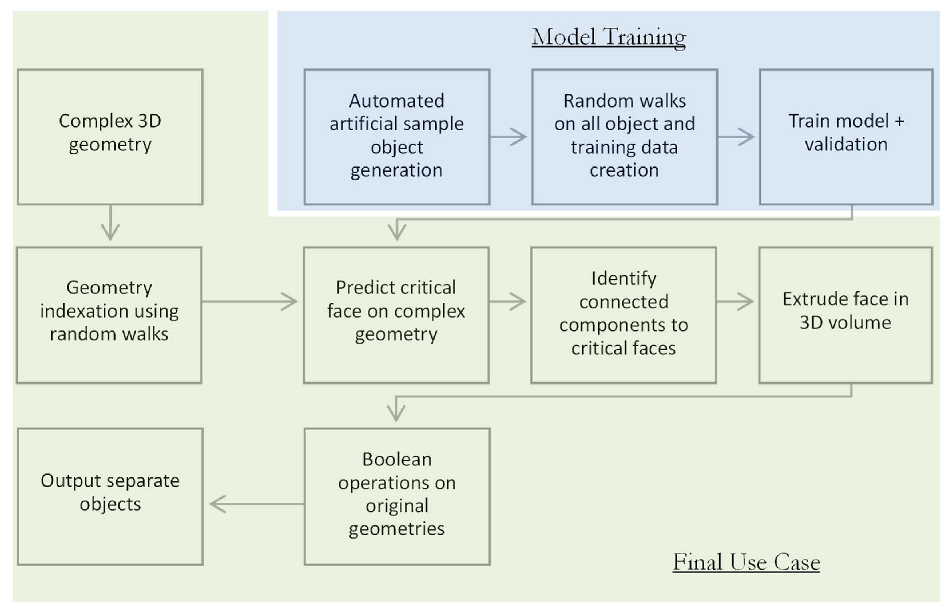
Table 1). This would allow for a simple definition of the features and an easily upgradable algorithm for new features depending on the material and process. Hence, materials that can be difficult to manufacture using LPBF such as Al- or Cu-based alloys will represent good candidates for the further implementation of this framework. A workflow combining the automatic generation of a database of geometries as per the definition in Table 1, the training of the machine learning algorithm based on the criticality of each feature, and the recognition and segmentation of an unknown geometry is presented in 
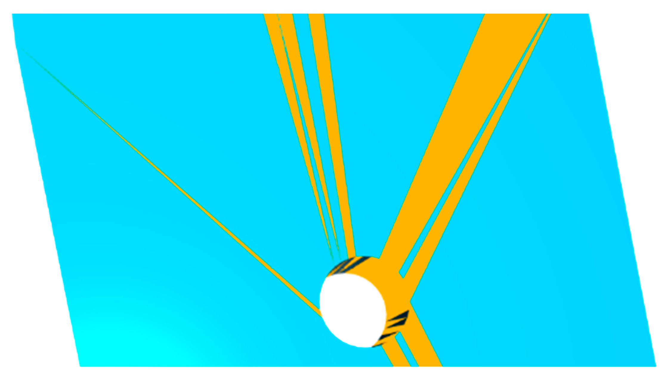
Figure 1. It is worth underlining that the goal of the recognition process is not to identify a 3D feature but rather a critical surface, which is further inflated in the direction of the part to apply segmentation.
It is not possible to work with the 3D representation of a part as a geometry input for the machine learning approach, because there is no systematic representation of a 3D object (e.g., triangle mesh quality, orientation). Hence, it is necessary to be able to register each geometry by applying mathematical methods. These methods presented below will turn the 3D object into a repeatable and comparable description of the geometry. For this purpose, a random walk algorithm is implemented on the triangle mesh. A random walk is a mathematical process that consists of exploring a mathematical space by going from neighbor to neighbor in a succession of random steps in that direction. In that case, the algorithm will consider the triangle mesh as the mathematical space and will jump to a neighboring triangle randomly (out of the 3 adjacent triangles). To collect the local features of a triangle mesh, the dual graph of the geometry is then created, i.e., a graph composed of nodes, each representing a face of mathematical body, and the link (edge) between the nodes representing adjacent faces. This dual graph is such that every triangle face of the STL file becomes a node, and the neighboring faces are connected with an edge. Note that every node of the dual graph has three degrees (i.e., having three edges) in this construction method, as only watertight objects are considered. To predict if a face is critical, a random walk is started at its node in the dual graph. The random walk outputs the concatenation of the face features. Each face is represented through the 3D coordinates of its corners and the face-normal vector. The face-normal is used to capture angles between neighboring faces.

2.3. Database Generation

A machine learning algorithm needs a training data set, consisting of thousands of individual points, some of them being critical and some not, to ensure a good training and validation process. The training dataset for the machine learning algorithm consists of simple geometries, which can be easily labeled as critical or non-critical. To generate a diverse set of samples, the features are sampled uniformly within the range of valid parameters defined in 
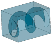
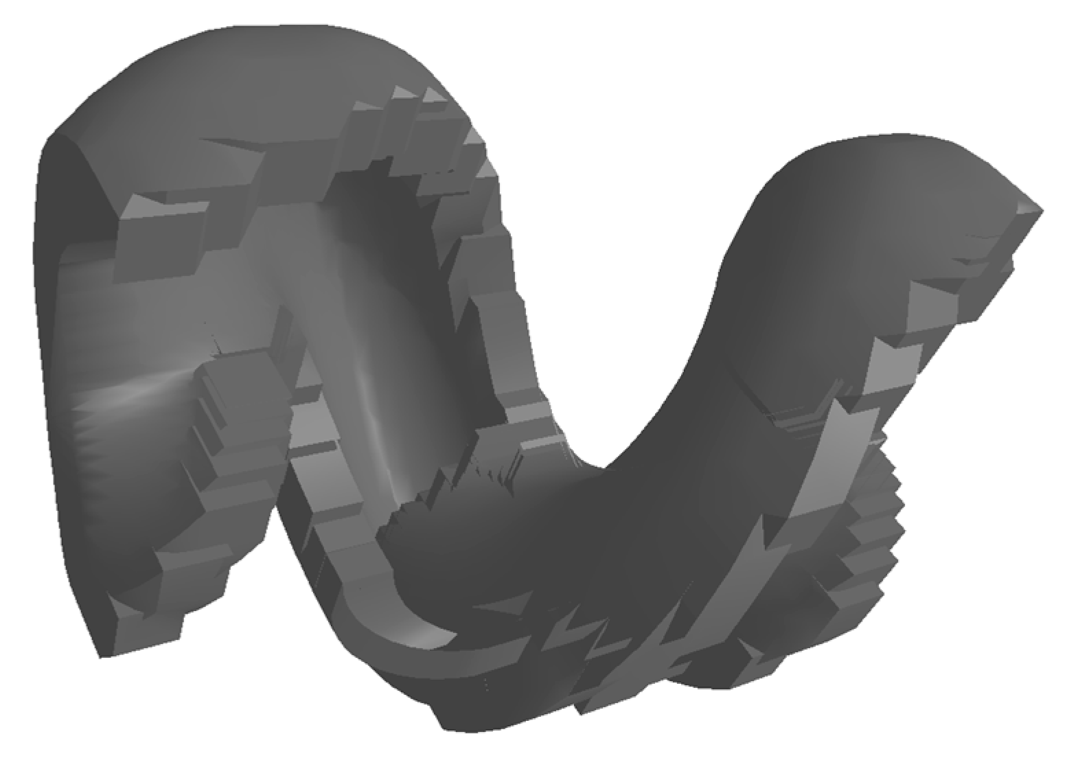
Table 1. An exception is made for the helix tube, which should be recognized by the intersection of other features. Additional geometries are generated as intersections of the features defined in Table 1, such as intersections of 3-mm-high random walls for walls with thicknesses ranging from 0.2 to 1.5 mm and with lengths ranging between 3 and 10 mm. Such wall intersections contain up to 12 intersecting elements. The generation of this dataset is completely automatized and randomized, and as such the data are representative of a complex geometry, as they consist of thousands of single features. However, the 3D representations of these geometries are not generated, only their mathematical description, as presented in the section above. This dataset, thus, represents a compilation of simple features and a total of 0.5 million random walk starting positions. This dataset is further randomly subdivided into a learning set (90%) and independent validation set (10%). A single training sample consists of a label indicating whether a triangle is critical and 20 random walks with lengths of 20 nodes in the dual graph starting from this triangle.

3. Results and Discussion

3.1. Machine Learning Efficiency

A convolutional neural network (CNN) architecture is trained with the goal of reaching a critical feature detection rate higher than 85%. To train deeper networks, residual layers (Resnet), as proposed by Szegedy et al. [16], are implemented. As a loss function, the binary cross entropy function is used. To model the problem as a regression predicting how critical a face is, the mean squared error is used as a predictor. The modeling as a regression problem is especially suitable for an additional manual step, where the final user can adjust the critical region by manually tuning an additional parameter indicating the cutoff for the critical region. An illustration of a geometry with surfaces of different critical levels is shown in Figure 2, where red represents highly critical and blue represents non-critical, as per Table 1. To accomplish better training, the batch normalization approach proposed by Ioffe and Szegedy [17] is implemented.
To ensure repeatability between geometries, the 3D geometry is not used in the CNN, and only the registered transcription of it, namely the dual graph, is used. The CNN architecture takes the dual graph parameters of the indexed geometry as an input layer. It is composed of the different parameters of the triangle mesh (3D coordinates of each triangle corners, the triangle normal vector, and the angles between neighboring triangles), as well as the random walk parameters (number of walks, length of walks). The input layer in this case has dimensions of (20,20,12), according to the description of the random walk in Section 2.2.
Multiple convolutions are applied in successive steps to create a map of the activation, so as to identify where the feature is located. The multiple convolutions are successively applied on the following parameters of the dual graph to create an activation map (also called the feature map in machine learning language, not to be confused with the geometrical features of this work):
  • On the parameters of a single triangle (3D coordinates of each triangle corner, the triangle normal vector and the angles between neighboring triangles);
  • On the random walk length;
  • On the random walk number of walks;
  • On the feature space (created by the first convolutions).
The last dimension is reduced to 8 in step 2 and to 16 in step 3. The tensors from the walk length, the number of walks, and the feature dimension are reshaped between each layer. Finally, an operator with multiple dense layers is applied for the prediction. The continuous reduction of the dimensionality of the hidden space leads to a network achieving a final detection rate of 88% on the validation set presented above, without overfitting, calculated on the validation data set (known critical features to be detected). In addition, a geometry composed of all trained features and an untrained feature (the helix hole) is successfully recognized and segmented (Figure 3).
The number of random walks and their lengths are set as fixed parameters to avoid any lack of data for the training. However, this produces a relatively large dataset, which needs to be reduced to optimize the training time. Regarding the indexation of the geometry before the machine learning algorithm, an alternative to the random walk approach would be to eliminate the randomness by building a feature tree, as presented by Classen et al. [18]. Such a feature tree would consist of every face rooted at its corresponding triangle in the STL file. The root degree of the feature tree equals three, and all other degrees equal two (some faces might be included multiple times), as the third neighboring triangle can be found on the path to the root. This approach is worth evaluating for further research, as it might capture the local topology without producing a dataset that needs to be reduced afterwards for training.

3.2. Segmentation of the Goemetry and Final Output

In addition to the validation from the generated dataset, the trained neural network is used for the recognition of features on parts containing multiple critical features. A successful geometry with recognition and segmentation, including a free overhang, horizontal hole, helix tube, and long overhanging surface, is presented in Figure 3a,c. This allows us to draw conclusions on the efficiency of the strategy in recognizing critical features on parts containing multiple critical features.
The validation of several other parts shows good recognition for the different features, yet some artifacts (e.g., neighboring triangles in hole openings) or instances of misrecognition are experienced, as per Figure 4. In such cases, the triangles that are not part of the hole (the critical feature to be recognized) are marked as critical. As the machine learning is only effective at 88%, these false positives are typically the margin of error.
Because the random walk process is in fact random, the results for different evaluations of the same triangles and their probabilities of being critical can change, but the critical areas always have triangles being recognized as critical. The answer is to conduct multiple evaluations and use the maximum from all evaluations or to filter the results by redistributing the critical behavior among the neighboring triangles to solve such issues. In addition, further training on more geometries and the validation of the results by the user will help the algorithm to avoid such false positives. These false positives are not present anymore in Figure 3, showing the efficiency of the multiple evaluation strategy. The recognition time increases with the increasing numbers of triangles on the model’s surface from a few seconds for the part presented in Figure 4 to several minutes for larger models, allowing for multiple evaluations at a reasonable cost.
The application of different process parameter settings to different features while knowing which faces are critical, as per Figure 3a, is insufficient, and the 3D objects are needed. This is accomplished by first generating a 3D volume from the critical surface and by applying Boolean operations between the original geometry and generated features. One object is the non-critical volume, i.e., the blue volume in Figure 3c, while the others are critical, which can be further treated in an AM build processor.
To generate the critical object from the critical surface, a ball cloud pivoting surface reconstruction algorithm, as presented by Bernardini et al. [19], is implemented. This allows the reconstruction of a triangle mesh from the mathematical description of the geometry by rotating a fictive “ball” around the first point selected until it reaches 3 points, then the triangle is formed and the ball is switched to the next point in the cloud of points. It is interesting to note that the marching cubes approach, as per the definition proposed by Lorensen and Cline [20], could represent a suitable and drastically faster solution, but smaller cubes result in gaps on the critical surface or require larger critical regions. As per Figure 3b, this method is not regular and not implementable for the clean resolution of each feature. A stair case effect is present on the overhanging surface, and the holes are poorly defined.
Finally, the implemented method eliminates the above problems by extruding each triangle individually if the number of triangles connected to each other is less than 100 triangles, while otherwise it uses a convex hull (smallest convex shape containing the number of points considered) algorithm-based method to fit the larger amount of critically connected triangles. This technical solution is fast and efficient. A complex structure such as the helix hole is easily modeled with a regular volume from the surface identified as critical, as per Figure 5.

4. Conclusions

The final results of this work can be summarized as follow:
  • A database of basic and hard-to-manufacture geometries was randomly generated from a known description with limits;
  • A CNN algorithm was implemented and fed with the database;
  • The final tuned algorithm permitted a success rate of 88% of recognition of typical hard-to-manufacture features in LPBF;
  • Untrained complex features (helix tube) can be successfully recognized;
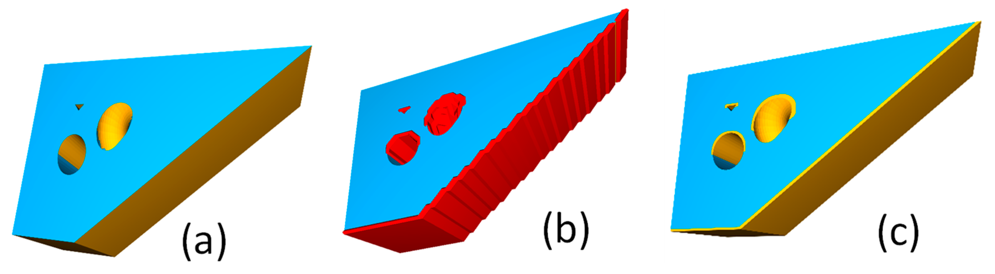
  • The segmentation of any feature can be successfully achieved.
Hence, the machine learning approach presented here is suitable for the complex problem of geometry segmentation. However, some process optimization approaches can still be used, notably for the topology indexation and the definition of the algorithm input space. The output of this classification of features is a collection of three-dimensional geometries representing the uncritical volume part, as well as the critical manufacturing features. For processes other than LPBF or other materials than standard steels in LPBF, a new definition of the features and their parameters (i.e., Table 1) is necessary. A new database could then be generated and the model could be retrained. This work is in favor of a richer file format for handling complex 3D models in the AM world, such as the 3mf format. This open-source, XML-based file format would be able to take into account the different features in a single file and let them be further treated by an AM build processor in an automated way. The further development of build processors is necessary to adapt to this new way of handling complex 3D parts. Further research on this topic should include processing capabilities to assign specific scanning strategies to each feature and more complex features recognition tools, such as lattice structures, on which tailored scanning strategies could also be proposed.

Author Contributions

Conceptualization, A.S.; methodology, A.S. and L.B.; software and investigations, L.B.; writing—original draft preparation and editing, A.S.; writing—review, A.B.S. and K.W. All authors have read and agreed to the published version of the manuscript.

Funding

This research received no external funding.

Data Availability Statement

Not applicable.

Conflicts of Interest

The authors declare no conflict of interest.

References

  1. Klahn, C.; Leutenecker, B.; Meboldt, M. Design Strategies for the Process of Additive Manufacturing. Procedia CIRP 2015, 36, 230–235. [Google Scholar] [CrossRef]
  2. Leutenecker-Twelsiek, B.; Klahn, C.; Meboldt, M. Considering Part Orientation in Design for Additive Manufacturing. Procedia CIRP 2016, 50, 408–413. [Google Scholar] [CrossRef]
  3. Calignano, F. Design optimization of supports for overhanging structures in aluminum and titanium alloys by selective laser melting. Mater. Des. 2014, 64, 203–213. [Google Scholar] [CrossRef]
  4. Staub, A.; Spierings, A.B.; Wegener, K. Selective Laser Melting at High Laser Intensity: Overhang Surface Characterization and Optimization. In Proceedings of the Direct Digital Manufacturing Conference, Berlin, Germany, 14–15 March 2018. [Google Scholar]
  5. Dursun, G.; Pehlivanogullari, B.; Sen, C.; Orhangul, A. An investigation upon overhang zones by using finite element modelling and in-situ monitoring systems. Procedia CIRP 2020, 93, 1253–1258. [Google Scholar] [CrossRef]
  6. Chen, H.; Gu, D.; Xiong, J.; Xia, M. Improving additive manufacturing processability of hard-to-process overhanging structure by selective laser melting. J. Mater. Process. Technol. 2017, 250, 99–108. [Google Scholar] [CrossRef]
  7. Finberg, N. Path Optimization for Laser Powder Bed Fusion Printing. Available online: https://blogs.sw.siemens.com/thought-leadership/2020/12/17/path-optimization-for-laser-powder-bed-fusion-printing/ (accessed on 11 February 2021).
  8. Niendorf, T.; Leuders, S.; Riemer, A.; Richard, H.A.; Tröster, T.; Schwarze, D. Highly Anisotropic Steel Processed by Selective Laser Melting. Metall. Mater. Trans. B 2013, 44, 794–796. [Google Scholar] [CrossRef]
  9. Chen, Q.; Liu, J.; Liang, X.; To, A.C. A level-set based continuous scanning path optimization method for reducing residual stress and deformation in metal additive manufacturing. Comput. Methods Appl. Mech. Eng. 2020, 360, 112719. [Google Scholar] [CrossRef]
  10. Druzgalski, C.L.; Ashby, A.; Guss, G.; King, W.E.; Roehling, T.T.; Matthews, M.J. Process optimization of complex geometries using feed forward control for laser powder bed fusion additive manufacturing. Addit. Manuf. 2020, 34, 101169. [Google Scholar] [CrossRef]
  11. Shi, Y.; Zhang, Y.; Baek, S.; De Backer, W.; Harik, R. Manufacturability analysis for additive manufacturing using a novel feature recognition technique. Comput. Aided Des. Appl. 2018, 15, 941–952. [Google Scholar] [CrossRef]
  12. Clijsters, S. Development of a Smart Selective Laser Melting Process; KU Leuven: Leuven, Belgium, 2017. [Google Scholar]
  13. Illies, O. Simulationsbasierte Thermische Analyse zur Anpassung der Hatching-Strategie beim Selektiven Laserstrahlschmelzen; Universität Bremen: Bremen, Germany, 2020. [Google Scholar]
  14. Wegener, K.; Spierings, A.; Staub, A. Bioinspired intelligent SLM cell. Procedia CIRP 2020, 88, 624–629. [Google Scholar] [CrossRef]
  15. Besl, P.J.; McKay, N.D. A method for registration of 3-D shapes. IEEE Trans. Pattern Anal. Mach. Intell. 1992, 14, 239–256. [Google Scholar] [CrossRef]
  16. Szegedy, C.; Ioffe, S.; Vanhoucke, V.; Alemi, A.A. Inception-v4, Inception-ResNet and the Impact of Residual Connections on Learning. In Proceedings of the Thirty-First AAAI Conference on Artificial Intelligence (AAAI-17), San Franciscio, CA, USA, 4–9 February 2017. [Google Scholar]
  17. Ioffe, S.; Szegedy, C. Batch Normalization: Accelerating Deep Network Training by Reducing Internal Covariate Shift. Proc. Mach. Learn. Res. 2015, 37, 448–456. [Google Scholar]
  18. Classen, A.; Heymans, P.; Laney, R.; Nuseibeh, B.; Tun, T.T. On the structure of problem variability: From feature diagrams to problem frames. In Proceedings of the International workshop on Variability Modeling of Software-intensive Systems, Limerick, Ireland, 16–18 January 2007; pp. 109–118. [Google Scholar]
  19. Bernardini, F.; Mittleman, J.; Rushmeier, H.; Silva, C.; Taubin, G. The ball-pivoting algorithm for surface reconstruction. IEEE Trans. Vis. Comput. Graph. 1999, 5, 349–359. [Google Scholar] [CrossRef]
  20. Lorensen, W.E.; Cline, H.E. Marching cubes: A high resolution 3D surface construction algorithm. In Proceedings of the Proceedings of the 14th Annual Conference on Computer Graphics and Interactive Techniques, Anaheim, CA, USA, 27–31 July 1987; pp. 163–169. [Google Scholar]
Figure 1. Workflow representation for machine learning training and final use case.
Technologies 10 00102 g001
Figure 2. Representation of different critical levels (not trained) for manual cut-off by the final user, where red is most critical and blue is non-critical.
Technologies 10 00102 g002
Figure 3. (a) The identified critical areas are shown in yellow. (b) The marching cubes before Boolean operation are shown in red. (c) The developed solution used for segmentation.
Technologies 10 00102 g003
Figure 4. The neighboring triangles of a critical hole are recognized as critical (yellow triangles, outside the hole) when using single-pass recognition.
Technologies 10 00102 g004
Figure 5. Extracted volume of the critical surface for a helix tube.
Technologies 10 00102 g005
Table 1. The features considered in this study and their parameters.
Feature Type3D ModelParameters Used
Overhanging surface Technologies 10 00102 i001(1) Overhang angle in the range of [10, 70°]
(2) Length of the overhanging plane in its growth direction in the range of [10, 25 mm]
Critical when over 45° and in the length range
Fine walls and slits Technologies 10 00102 i002Wall thickness in the range of [0.1, 15 mm]
Critical between 0.1 and 5 mm
Horizontal and vertical holes Technologies 10 00102 i003Diameter in the range of [2, 15 mm]
Critical between 6 and 15 mm
Helix tube Technologies 10 00102 i004The helix tube is a complex variation of different features that should be recognized
Publisher’s Note: MDPI stays neutral with regard to jurisdictional claims in published maps and institutional affiliations.

