Article

Effective Current Pre-Amplifiers for Visible Light Communication (VLC) Receivers

by
Simon-Ilias Poulis
1,*,
Georgios Papatheodorou
1,
Christoforos Papaioannou
1,
Yiorgos Sfikas
1,
Marina E. Plissiti
1,
Aristides Efthymiou
1,
John Liaperdos
2 and
Yiorgos Tsiatouhas
1
1
Department of Computer Science & Engineering, University of Ioannina, GR-45110 Ioannina, Greece
2
Department of Digital Systems, School of Economy and Technology, University of the Peloponnese, GR-23100 Sparta, Greece
*
Author to whom correspondence should be addressed.
Technologies 2022, 10(1), 36; https://doi.org/10.3390/technologies10010036
Submission received: 31 December 2021 / Revised: 9 February 2022 / Accepted: 11 February 2022 / Published: 21 February 2022
(This article belongs to the Special Issue MOCAST 2021)

Abstract

:
Visible light communication (VLC) is an upcoming wireless communication technology. In a VLC system, signal integrity under low illumination intensity and high transmission frequencies are of great importance. Towards this direction, the performance of the analog front end (AFE) sub-system either at the side of the transmitter or the receiver is crucial. However, little research on the AFE of the receiver is reported in the open literature. Aiming to enhance signal integrity, three pre-amplification topologies for the VLC receiver AFE are presented and compared in this paper. All three use bipolar transistors (BJT): the first consists of a single BJT, the second of a double BJT in cascade connection, and the third of a double BJT in Darlington-like connection. In order to validate the performance characteristics of the three topologies, simulation results are provided with respect to the light illumination intensity, the data transmission frequency and the power consumption. According to these simulations, the third topology is characterized by higher data transmission frequencies, lower illuminance intensity and lower power consumption per MHz of operation.

1. Introduction

Visible light communication (VLC) is a promising scientific field in which the interest of the research community has increased significantly during the last decade. The term VLC stands for a wireless communication system which uses the visible spectrum of light (380 nm to 750 nm, 430 THz to 750 THz) as the medium for transmitting information. Although the idea of using visible light in communications is not new [1], it was not until the beginning of the year 2000 that there were the first VLC experiments using light-emitting diode (LED) lamps. In fact, in [2] a white LED was used for simultaneous illumination and data transmission in an indoor space. That research was a springboard for optical wireless communications (OWC), increasing the research interest and leading to major innovations, such as new configuration techniques, new LED technologies and more. The year 2011 was a milestone for VLC. Initially, a first demonstration of a Light Fidelity (Li-Fi) network during a TEDx talk by Harald Haas [3] highlighted the innovation brought about by this promising wireless communication and resulted in an exponential increase on research output related to VLC, OWC and free-space optical communications (FSOC). Later in the same year, the IEEE included OWC/VLC in the official IEEE Standard for local and metropolitan area networks [4].
There are different types of OWCs that can use LEDs or laser diodes (LDs) as transmitters and photodiodes (PDs) or image sensors (IS) as receivers. Also, depending on the proposed technology, the physical means of communication may be the infrared (IR), visible light (VL) [5,6] or ultraviolet (UV) part of the electromagnetic radiation of light [7]. This new technology has some significant advantages such as the use of existing lighting infrastructure both for illumination and communication. Considering the gradual replacement of traditional lighting by LED lamps, the energy consumed for lighting is useful, in a twofold manner. However, in mobile devices the energy consumption by the LEDs used remains considerable.
The bandwidth of visible light is one of VLC’s most important advantages over radio frequency (RF) communications. It is about 1000 times wider than the spectrum of radio frequencies, thus significantly reducing the possibility of channel congestion. In addition, the high frequency of electromagnetic waves of visible light (of the order of THz) can allow very high-speed data transmission. More specifically, compared to Wi-Fi, where the highest data rate reaches 1 Gbps (in the Wireless Gigabit (WiGig) standard [8]), studies on optical communications report data rates up to 100 Gbps, as in [9] where a LD is used.
VLC can also provide significant advantages in data security options compared to radio wave links, since visible light waves do not have the ability to penetrate through opaque solid surfaces like radio waves, making VLC safer than radio wave communications. In addition, all electromagnetic radiation that does not belong to the visible spectrum, even when very close to it, such as infrared and ultraviolet, tend to be harmful to human health or cause interference to machines, such as pacemakers and other important medical equipment. On the contrary, radiation belonging to the visible spectrum does not cause such interference and is harmless, making VLC safe for humans.
Apart from the above, VLC technology demonstrates a wide range of applications, such as internet connectivity, underwater communications, and even interplanetary communications. Furthermore, there are three applications that mainly attract research interest: (i) indoor VLC systems, (ii) transport and vehicular VLC systems and (iii) indoor positioning systems.
The study of indoor VLC systems arose due to the long periods that people spend inside buildings and the idea started to become a reality due to the gradual prevalence of LED lamps. In [10] the authors studied the possibility of using LEDs for VLC systems, presenting the requirements for such a system to act for lighting and communication at the same time. Nowadays, numerous buildings provide lighting with multiple LEDs where multiple input multiple output (MIMO) techniques can be applied, regardless of the type of physical medium configuration. In [11] a MIMO orthogonal frequency division multiplexing (MIMO–OFDM) system with a transmission speed of 220 Mbps at a distance up to 1 m between the transmitter and the receiver is reported, while in a recent work of the same research team [12], a speed of 1.1 Gbps was achieved at the same conditions.
In a VLC system, data transmission takes place, even when the light in an indoor space is dim or even switched off. In [13] the authors proposed a VLC system in which data transfer is performed even if the lamp remains switched off for human perception or at low intensity.
Using VLC in vehicles is also very advantageous, since its application cost can be relatively low, as the use of LED lamps is trivial. Also, a variety of light sources is available on the roads, such as car headlights or traffic lights, which can be used to develop intelligent transport systems (ITS) [14], as they can establish a line of sight (LoS) VLC system. A vehicular VLC (V2LC) system requires one or more mobile (vehicles) and fixed (traffic lights, streetlights) nodes. The nodes need to obtain transmitters and receivers to create a dynamic communication network, to transmit any useful information collected by sensors embedded in the vehicles and the environment [15], while at the same time an important possibility for these networks is a direct vehicle-to-vehicle (V2V) communication.
With the development of the Internet of Things (IoT) and the continuous growth of mobile devices, new applications are available offering new possibilities to the end users. Such features are related to personal navigation and information or advertising depending on the user’s location. In order to achieve the above features, location capabilities are required. VLC technology can provide indoor localization, with great precision using existing lighting–communication infrastructure. Thus, the receiver will capture the signals off the LEDs and with appropriate algorithms the exact position will be determined.
High-precision internal positioning systems, such as Epsilon [16] and Luxapose [17], have come to light since 2014. In the former, many LED lamps (transmitters) and photodiodes (receivers) were used to easily implement a low-cost system, with the ability to find the position with an error of 0.4 m. In Luxapose, the receivers were image sensors (IS) from a smartphone camera, having only a 0.1 m internal detection error, while providing the ability to orient the device.
VLC is therefore a promising communication technology, which will be of great concern to the research community in the coming years, either as a complementary technology to the already existing wireless communications, or as the main means of wireless communication. Although the pertinent IEEE standard has been revised since 2018 [18], research is still at an early stage in this field, as the full operating framework has not yet been defined.
As mentioned above, the range of applications for optical wireless communication is wide resulting in a dispersion of research towards various directions. Also, beyond the applications, the attention of the research community has focused on various parts of the physical layer (PHY), such as the transmitter–receiver architecture, the coding–signal modulation and the multiplexing of multiple users.
Since the initial release of the IEEE standard [4], different modulation and coding schemes have been proposed at the PHY level, depending on the application usage of a VLC system. Typical modulation schemes are on-off keying (OOK), color shift keying and variable pulse position modulation (VPPM) for VLC systems using photodetectors such as PDs. Respectively, in the revised version of the standard [18] modulation schemes were added such as camera on-off keying (C-OOK), rolling shutter frequency shift keying (RS-FSK) and others, related to the use of the IS of digital cameras.
In addition to the proposed standard schemes, the research interest has turned to various data multiplexing schemes such as OFDM, MIMO, wavelength division multiplexing (WDM) and others or combinations thereof, in order to achieve high transmission rates. For example, in [12] an optical modulation technique for MIMO–OFDM is proposed, while in [19] a performance improvement of M-quadrature amplitude modulation (M-QAM) OFDM–non-orthogonal multiple access (NOMA) is presented. At the same time, in [20] a 16-QAM OFDM transmission scheme with rates of 4 Gbit per second is proposed and in [21] a LED-based wavelength division multiplexing (WDM) scheme achieving a 10 Gbps data rate is presented. Moreover, an additional area of interest for a more complete coverage of the optical channel are the multiple access methods, with NOMA so far seeming to gain most research interest [22,23], due to the significant improvement of the spectral performance of the channel.
Also, an important issue that arises in VLC is the elimination of flickering using coding schemes, in the existing formatted optical signal, such as run-length limiting (RLL) and Reed–Solomon (RS) encoders, with simultaneous clock recovery and error detection capability [18]. Although the above encoding schemes are well defined by the standard, there is considerable research on alternative ways of error detection and correction, such as the use of polar code (PC) instead of RS in CSK modulation VLC systems [24] or with a protograph low-density parity-check (LDPC) code of two types [25].
Today, the research mainly focuses on the transmitter with respect to the power supply, the LED characteristics [26] and the LED driving sub-circuit [27,
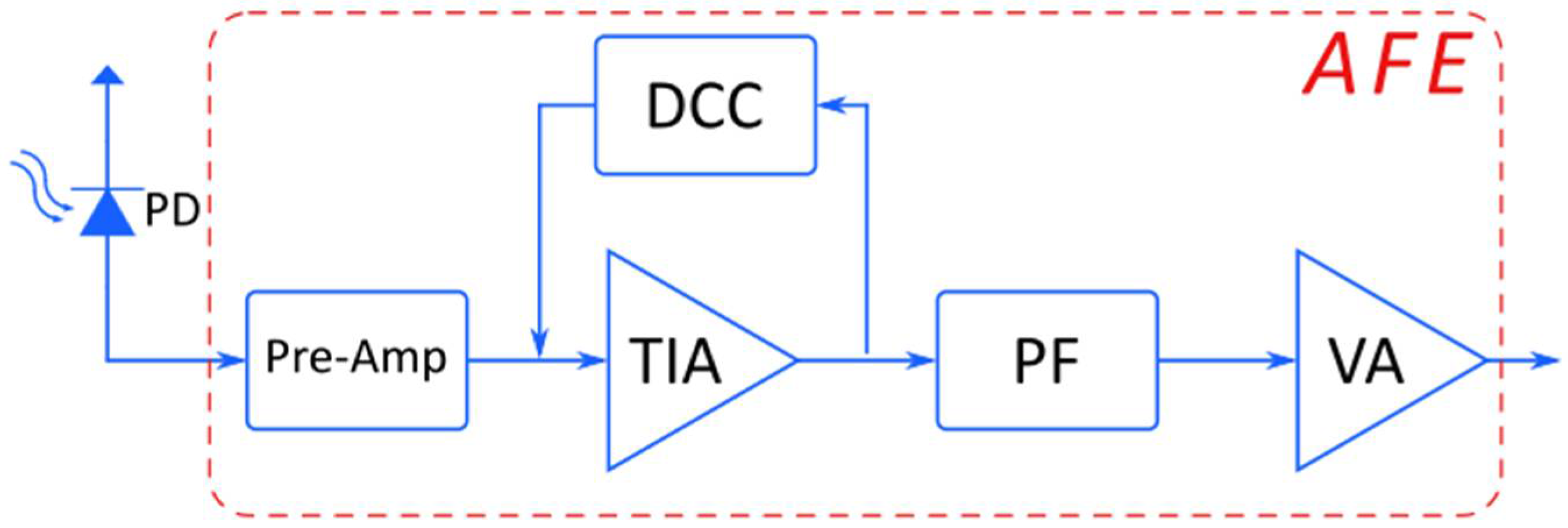
28]. However, considering the receiver of a VLC system, the research activity is not extensive enough. Meanwhile, the AFE of the receiver constitutes an equally important part of a VLC system. It receives the visual signal and converts it to an electrical one that is filtered and amplified in order to be digitized and processed. The limited number of studies in the literature are mainly focused on the receiver architecture at a basic level, such as the use of the trans-impedance amplifier (TIA) to amplify the received signal [29]. Therefore, the research on the AFE of the receiver is essential as it contributes to the smooth operation of a VLC system.
In this paper, three effective current pre-amplification topologies that supplement the AFE of VLC receivers are presented and simulation results are included. The three topologies are compared with respect to their characteristics that are related to, (1) the illuminance falling on the photosensitive surface of the receiver photodiode, (2) the transmission frequency of the optical signal and (3) the total power consumption of the receiver. The paper is organized as follows. In Section 2 preliminaries on VLC systems are given. Next, in Section 3 the AFE of a VLC system is discussed and the three current pre-amplification topologies are presented. In Section 3, simulation results are provided on the performance characteristics of the three topologies. Finally, in Section 4 the simulation results are discussed.

2. Preliminaries

In a VLC system, information is transmitted through the visible light. The transmitter modulates the light (e.g., on-off switching or continuous changes of light intensity) in a way that is not perceived by the human eye. In this way, both the illumination and the information transmission needs are covered simultaneously. The operation is achieved either by using LEDs that support both functions or by using dedicated LEDs for data transmission while supplementing the required room illumination with other light sources that are exploited only for lighting.
From the above discussion, it is well understood that the information transmission must be carried out at a frequency that the human eye cannot perceive. This frequency has been already defined by the pertinent IEEE standard at above 200 Hz [4] and reconfigured by its revised version in 2018 [18] at above 2 kHz.
On the receiver side, the optical signal can be retrieved primarily either by using a photodiode or the sensor of the built-in camera of a portable device. These two approaches have essential differences that are exploited by several applications depending on the data transmission frequency. For example, since a built-in camera supports lower data rates (in the order of a few kHz), it can be used in an indoor location and navigation system. On the contrary, as photodiodes can respond to much higher frequencies (in the range of a few MHz) their use in applications that support higher data rates is preferred.
Furthermore, the reverse current of a photodiode may be in the range of some tenths of μA up to 200 μA depending on the photodiode model. This feature can be crucial in a VLC system since such a small input current signal may distort data resulting in incorrect reception of the transmitted information.

3. Visible Light Communication (VLC) Receiver and Pre-Amplification Circuits

Our work focuses on a receiver circuit that uses a photodiode as the optical signal sensor. The basic structure of the AFE of the VLC receiver under consideration consists of: (a) a photodiode (PD), (b) a pre-amplification circuit (Pre-Amp), (c) a TIA, (d) a DC cancellation circuit (DCC), (e) a passive filter (PF) and (f) a voltage amplifier (VA), as shown in the block diagram of Figure 1.
More specifically, the optical signal is converted through the photodiode into a current signal. This signal, after its pre-amplification, drives the TIA, which is supported by the DCC circuit, for the conversion to a voltage signal without its DC offset. Then, the signal is passed through the passive filter that eliminates any unwanted frequencies. Finally, the signal is amplified at appropriate levels by the VA in order to be digitized and drive a microcontroller or microprocessor, which will decode it and retrieve the information.

3.1. VLC Receiver

In more detail, for the VLC receiver design the TIA–DCC sub-circuits proposed in [30] were adopted in our work, while the anti-aliasing filter used in [30] was replaced by a high-pass filter and a voltage amplifier, as shown in Figure 2.
The combination of the TIA and DCC blocks (“Ambient Light Filter” in [30]) achieves the elimination of the DC offset from the signal and has the ability to self-adjust according to the average light intensity changes that are taking place in the lighting of the room. It is a very versatile active filter with its cut-off frequency set at 340 Hz.
The signal provided by the TIA–DCC blocks, without the DC offset, enters a high-pass passive filter with a cut-off frequency of 3 MHz. Finally, the filtered signal enters a voltage amplifier, powered by a single (positive) supply VCC at 3.3 V, which acts as a half rectifier eliminating the negative part of the signal. The gain of the VA is 43.58 dB which is large enough to support easy digitization of the signal.

3.2. Pre-Amplification Circuit Topologies

According to our observations, the above typical receiver AFE topology presents serious signal integrity problems at low light intensities. For that reason, three pre-amplification topologies are explored in this work. The common feature of all three topologies is that bipolar transistors were chosen as their basic unit. Thus, the current of the photodiode controls the collector current of a transistor, forming a current source controlled by current.
The three topologies under consideration are: (i) a single BJT current amplifier, (ii) a double BJT in a cascade connection current amplifier and (iii) a double BJT in Darlington-like connection current amplifier. These topologies are presented in detail in the following paragraphs.

3.2.1. Single Bipolar Transistor (BJT)

The first pre-amplification topology, along with the photodiode, is shown in Figure 3. It is the simplest topology consisting of a bipolar transistor where its base is fed by the current signal produced by the photodiode. The base current is amplified at the collector according to the BJT current gain factor (hFE) and the amplified current signal drives the TIA–DCC blocks.

3.2.2. Double BJT in Cascade Connection

The second topology consists of two BJTs in cascade connection as shown in Figure 4. Its basic operation principle lies in the amplification provided by each BJT. Here, the incoming current signal is amplified via the BJT current gain factor hFE1 and the emitter current of the first BJT is obtained. The emitter current of BJT1 feeds the base of BJT2 which in turn is amplified by the current gain factor hFE2 and drives the TIA–DCC block. It should be noted that the RC network (with cutoff frequency of 80 kHz) is used to limit the DC offset of the current on the BJT1 collector and consequently is exploited to control the collector current of the first stage.

3.2.3. Double BJT in Darlington-Like Connection

This topology also uses two BJTs but in a Darlington-like connection. Figure 5 presents the circuit which differs with respect to a typical Darlington scheme, due to the existence of the resistor at the collector of BJT1. This resistance is exploited to regulate the amplification and consequently to provide a better control of the amplified current signal that feeds the TIA-DCC block. As mentioned earlier, the BJT1 collector resistance provides a self-control capability of the current at the base of BJT2, aiming to reduce the DC current amplification.

4. Simulation Results

In this section, initially, the components in Figure 2, Figure 3, Figure 4 and Figure 5 that were used for the design of the VLC receiver under consideration are discussed. Next, the electrical model of the photodiode is presented and the structure of a typical signal that feeds a VLC receiver is analyzed. Both are exploited in the simulations of the receiver, which were performed in the LTSpice XVII platform of Analog Devices. Finally, the simulation results are presented that provide comparisons among the three pre-amplification topologies.

4.1. VLC Receiver Design

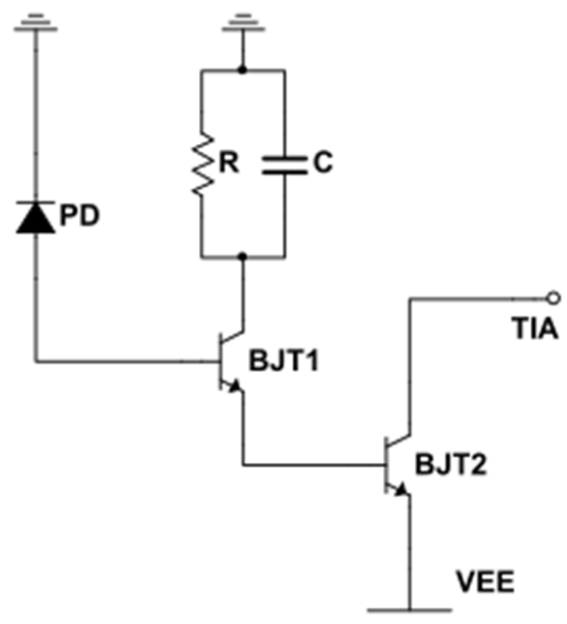
The AFE circuitry of the VLC receiver in Figure 2 along with the three pre-amplification topologies were designed using the schematic editor of the LT-SPICE platform. The components of the various parts in the design are presented in Table 1. For each one of them the Spice models of the manufacturers are exploded at the simulations, except the PD. The selection of the components was based on their ability to support the specifications of the receiver that are related to the response time, the bandwidth, the operating frequency and the slew rate.
The OSRAM SFH-206K [31] photodiode was chosen, as this component has a spectral sensitivity between 400–1100 nm, which is satisfactory for a VLC system. In addition, it has quite small rise and fall times, along with an appropriate current intensity and linearity with respect to the incident luminous flux per unit area of the photodiode. For the needs of our VLC system, the photodiode provides a 40μA current for an incident luminous power of 500 Lux on the surface of the photodiode.
The Analog Devices LTC6228 [32] low-distortion operational amplifier was selected for the TIA and the VA. This opamp is characterized by low noise, down to 0.88 nV/√Hz, high slew rate that reaches 500 V/us and the rail-to-rail output ability.
Unlike the cases of the TIA and VA, for the selection of the operational amplifier for the DCC sub-circuit there are no special specifications, as the DCC is the least demanding part of the receiver. Thus, the Analog Devices ADA4622 [33] opamp was chosen.
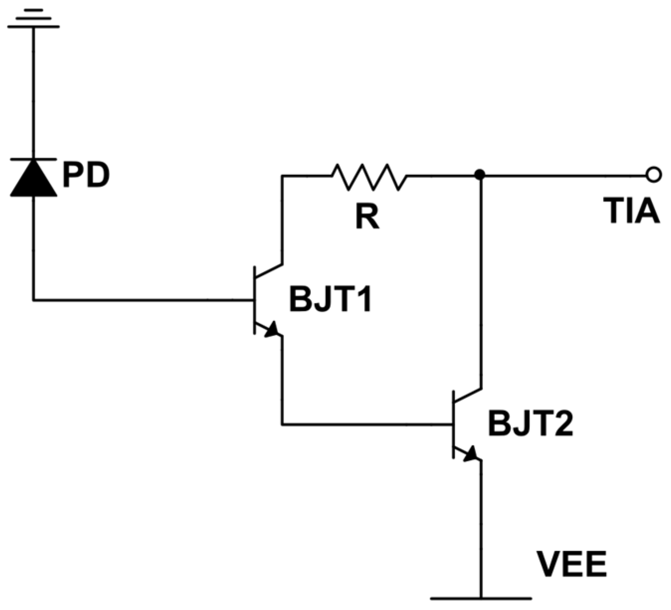
Finally, the Infineon Technologies BFR-340F [34] bipolar transistor was selected for the pre-amplification topologies under consideration. This component is an RF bipolar transistor with 14 GHz typical transition frequency and low capacitance coupling between its terminals.

4.2. Photodiode Electrical Model

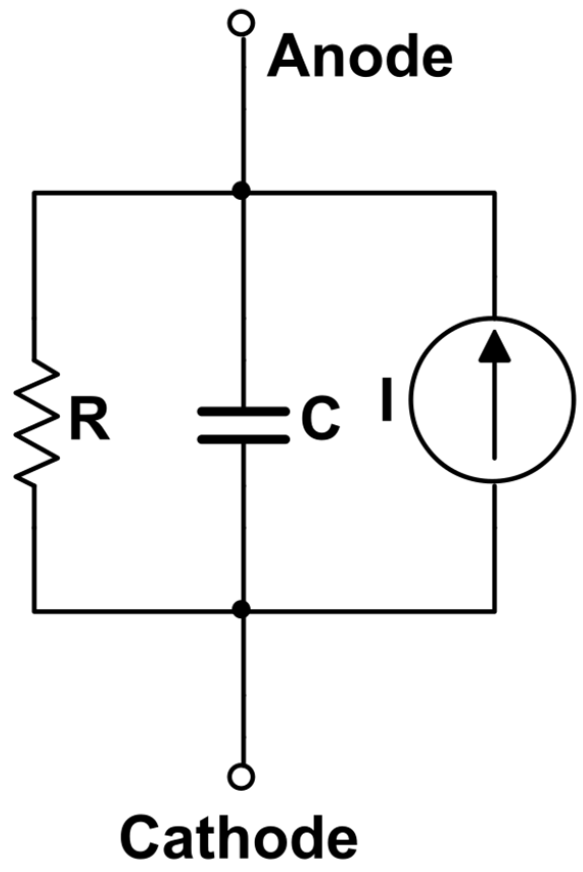
To conduct the simulations of the receiver, an appropriate electrical model for the photodiode under consideration was necessary. Towards this direction, a proper sub-circuit was developed, according to the photodiode datasheet, using the typical topology shown in Figure 6 for a photodiode in reverse bias. In this model, the photodiode current is correlated with the actual illuminance intensity values.
Τhe photodiode model consists of a current source, a capacitor and an ohmic resistor in parallel connection, as it is depicted in Figure 6. Capacitance and resistance values correspond to the SFH–206K datasheet values, while the current source amplitude is determined by the linear relationship between illuminance and photocurrent, as it is extracted from the pertinent datasheet diagram. Furthermore, the rise and fall times of the photodiode were also taken into account in this model.
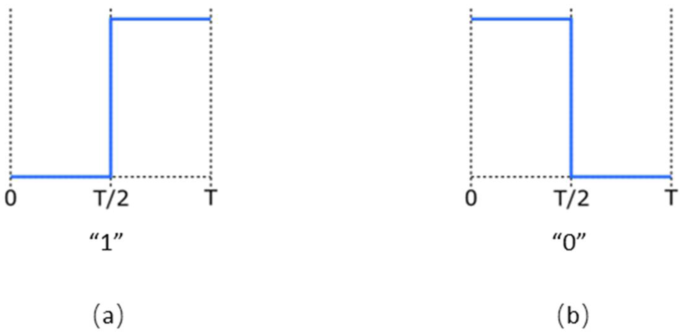
In order to use a realistic current signal, it was necessary to consider an appropriate data-encoding method according to the IEEE standard [18]. The Manchester encoding was chosen, where the logic high bit (“1”) is encoded with a low to high transition during one period of the system clock (Figure 7a), while the logic low bit (“0”) is encoded with a high to low transition accordingly (Figure 7b).
Manchester encoding, although simple, is essential in a VLC system since it prevents an intense change in the brightness of the transmitter’s light in the case of consecutive “1” or “0” bits. Thus, the human eye is protected from perceiving light brightness perturbations since it keeps a constant average light intensity, for signal frequencies above the minimum specifications of the standard.
In order to simulate a realistic operating scenario for the receiver, a Manchester-encoded 24-bit input sequence was created that is followed by an empty span of 16-clock periods. This results in the creation of a data package and a blank space after that, which is continuously repeated as shown in Figure 8. The generated sequence controls the current source of the photodiode model in Figure 6. The pulse amplitude and max frequency are determined according to the incident luminous power and the system clock frequency, respectively.
Figure 8 illustrates the generated and “transmitted” 24-bit data sequence, according to the Manchester encoding. This data sequence (package) consists of pulses of longer or shorter duration. A short duration pulse corresponds to the transmission of the same bit value repeatedly, while a longer pulse corresponds to a bit change. According to Figure 8, in our simulations a package consists of 19 pulses, with a period equal to the system clock period (T) for a short pulse and a period 2T for a long pulse.
In practice, in a real usage scenario, the transmitted package would be much larger, since according to the standard, additional bits are required for the transmission of the information, such as appropriate headings, redundancy bits for error correction etc. However, without loss of generality, for the needs of the present work, the selection of such a data package is totally adequate as it provides all the characteristics of a real signal.

4.3. Simulation Assumptions

In this work, we assume that the average illuminance that falls on a work desk is 500 Lux, since with this illuminance a person can work or study uninterruptedly [35]. Simulations were conducted considering three main characteristics: (a) the intensity of the incident light flux per unit area of the photodiode, (b) the information transmission frequency and (c) the power consumption of the entire AFE along with the pre-amplification stage. When one of the two characteristics is explored (light intensity or transmission frequency), constant conditions were chosen for the other one, by considering realistic values for the proper validation of the receiver.
Aiming to define the working range of the receiver under various operating conditions, the basic criterion for the first two factors is the signal integrity at the output of the AFE. The signal integrity is lost even when a single bit from the data sequence in Figure 8 is lost at the output of the AFE. By considering that the transition threshold at the input of the digital block that follows, which is driven by the AFE, is at Vdd/2, a bit is lost when an expected output signal transition does not pass this threshold.

4.4. Incident Illuminance Intensity on the Surface of the Photodiode

In order to determine the influence of the light power intensity on the receiver operation, the illuminance intensity value (Lux) was changed in the subcircuit of the photodiode by changing its photocurrent accordingly. A constant signal transmission frequency of 5 MHz was considered as a typical frequency of the system.
It was also observed that there is no differentiation between the three AFE variations when illuminance is increased, while low values of illuminance present an observable differentiation as described below.
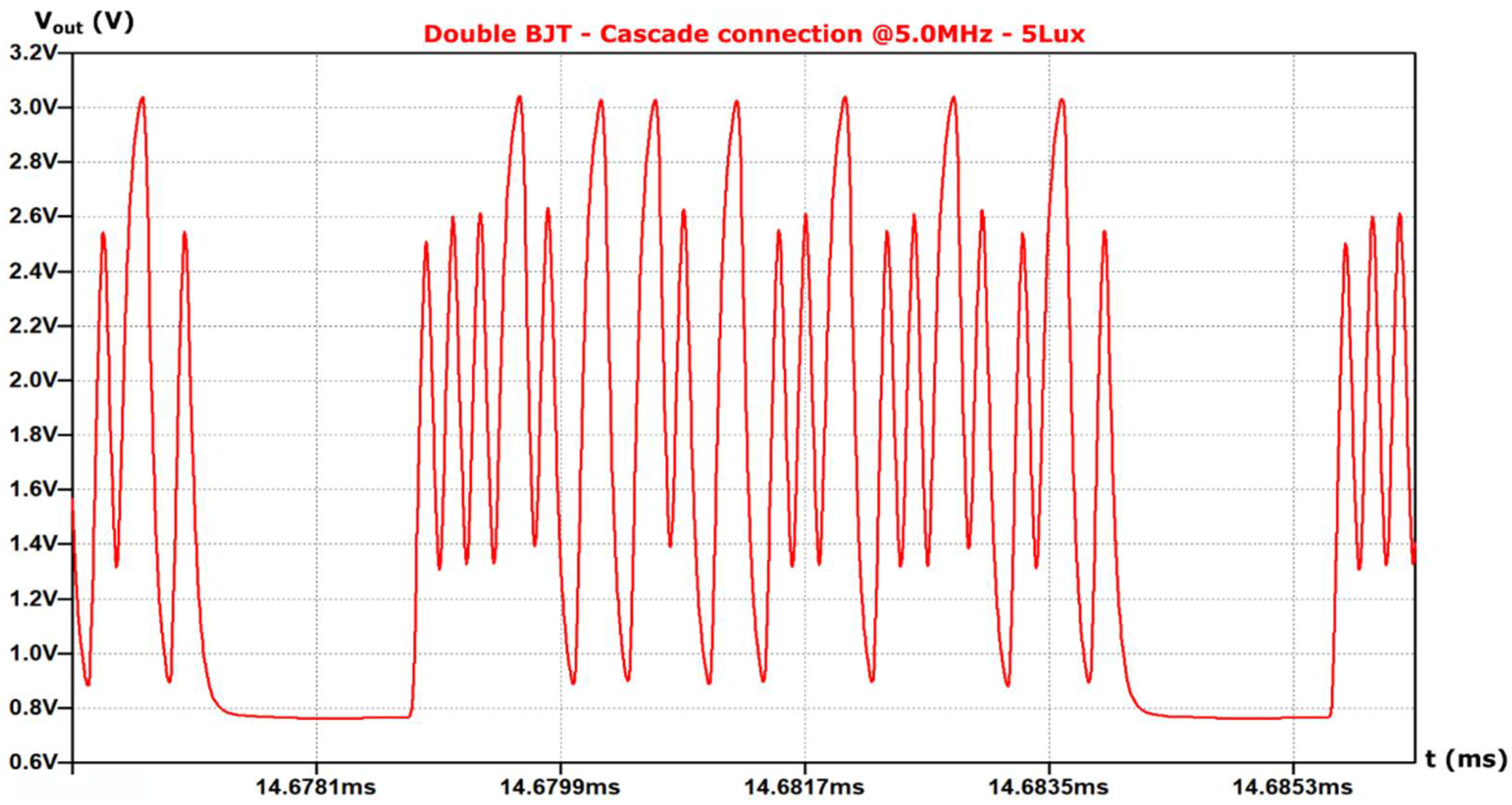
For the first pre-amplification topology (I) (single BJT), as the incident illuminance in the photodiode decreases, the signal integrity is lost at 95 Lux, as shown in Figure 9. On the contrary, for the pre-amplification topologies (II) and (III), the signal integrity is lost at the illuminance of 5 Lux, as shown in Figure 10 and Figure 11 respectively. Note that for the AFE topology without pre-amplification signal integrity issues arise below 120 Lux.
Topologies (II) and (III) present similar behaviors and they are clearly superior over (I) when the sensitivity to the illuminance intensity is considered.

4.5. Data Transmission Frequency

Next, the data transmission frequency efficiency of each topology is considered. For this purpose, the light intensity (and consequently the corresponding photocurrent) was kept constant at the value of 500 Lux.
Unlike the previous simulation results, the proposed topologies presented no differentiation for lower frequencies, while they did when transmission frequency increased.
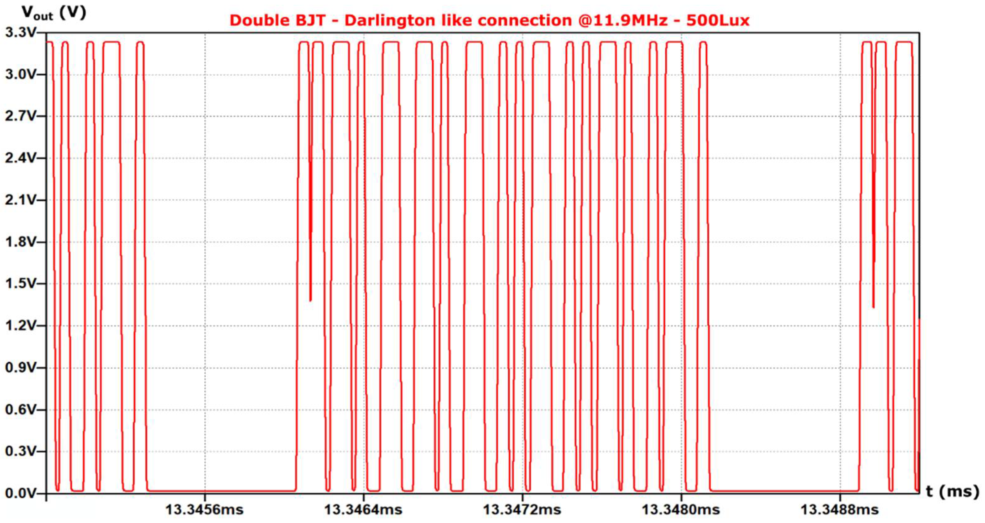
When the frequency varies, the signal remains intact for topology (I) up to the frequency of 7.9 MHz, as shown in Figure 12, while for topology (II) up to 11.25 MHz (Figure 13) and for topology (III) up to 12.05 MHz (Figure 14), respectively.
Again, topology (I) seems to lag behind the other two topologies in terms of data transmission frequency. However, topologies (II) and (III) also present differentiations, with topology (III) being able to provide approximately 650 kHz higher data transmission frequency than topology (II).

4.6. Receiver Analog Front End (AFE) Power Consumption

Two types of simulations were performed on each AFE circuitry in order to examine the power consumption of the receiver in relation to the signal transmission frequency and the illuminance intensity. When the frequency is changed, the light intensity was set at 500 Lux, while when the light intensity is changed, the frequency was set at 500 kHz.
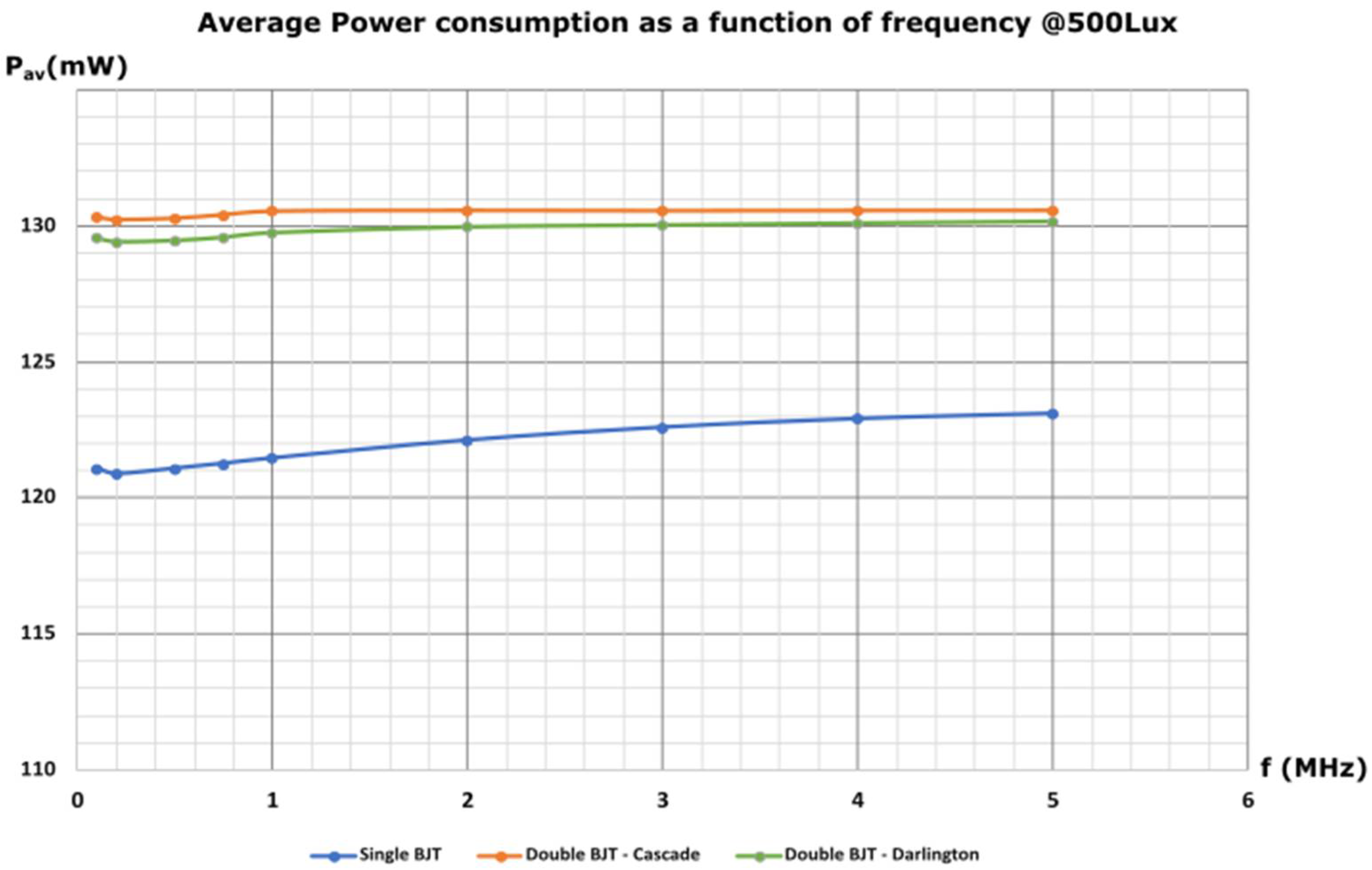
The average power consumption of the receiver AFE as a function of frequency for the three topologies (at 500 Lux illumination intensity) is presented in Figure 15.
As it can be observed in Figure 15, the frequency variation has little effect on the power consumption of each topology. More specifically, from 100 kHz to 5 MHz, the power consumption varies by 1.02% for topology (I), 1.003% for topology (II) and 1.006% for topology (III). However, with respect to topology (I), topology (II) presents a higher power consumption by 6.926% on average and topology (III) by 6.436% on average, respectively.
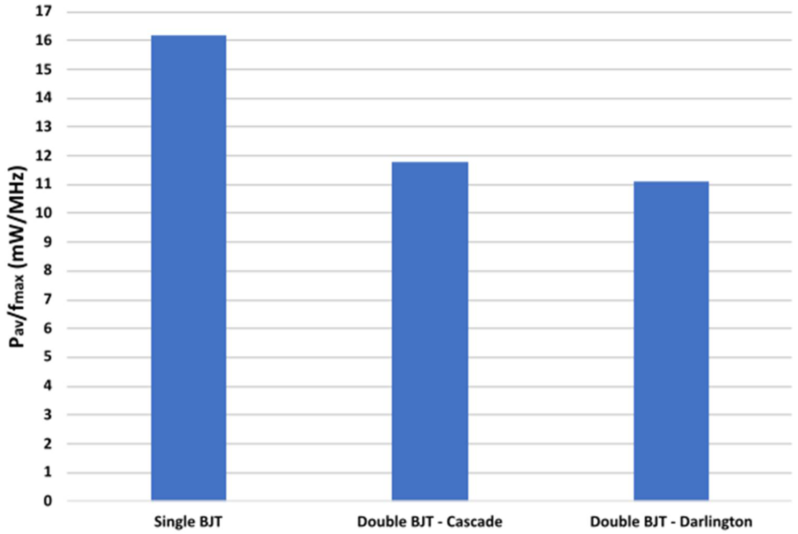
According to the above simulations on power consumption and considering the maximum operating frequency of each topology, the power consumption per MHz is extracted for the three topologies. Thus, the average power consumption per MHz reaches 16.18 mW/MHz, 11.78 mW/MHz and 11.13 mW/MHz, for topologies (I), (II) and (III), respectively (Figure 16).
Moreover, the average power consumption of the receiver AFE as a function of illumination intensity for the three topologies (at a constant frequency of 500 kHz) is presented in Figure 17. The 500 kHz frequency was chosen aiming to reduce the simulation time, given that the frequency does not influence the power consumption, as discussed above.
In Figure 17 we observe that the variation of light intensity affects the power consumption. For each topology, it is obvious that the slope of the curves is similar. However, topologies (II) and (III) consume respectively on average 8.04% and 7.45% more power compared to topology (I).

5. Discussion and Conclusions

Although VLC is a promising technology there is a lack of extensive research activity on the receiver AFE design. Aiming to cover this area, we explore three pre-amplification topologies for the AFE of a VLC receiver, in order to improve the efficiency of this optical communication system, since typical AFE, without pre-amplification, are characterized by reduced signal integrity at low illuminance. In more detail, the typical AFE reaches an output voltage swing of 1.27 V at 5 MHz and 120 Lux. Referring to Figure 10 and Figure 11, the AFE with either the pre-amplification topology II or III, has the same output voltage swing at the luminous flux of 5 Lux at the same transmission frequency. The light intensity of 5 Lux is 95.8% below the light intensity of 120 Lux and that means that the topologies II and III are more sensitive and capable to operate with smaller light signals than the typical AFE circuit without pre-amplification. Furthermore, the AFE with the pre-amplification topology I has a large, rail-to-rail, output voltage swing at 5 MHz and 95 Lux, which is 20.8% lower than the 120 Lux. All of the above indicate that the typical AFE is more prone to potential noise and less effective at low light signal intensities.
According to the simulations performed on the three topologies of the receiver AFE, it is stated that topology (III) provides the highest data transmission frequencies, 50.6% over topology (I) and 5.78% over topology (II). Topologies (II) and (III) support in parallel operations at low illuminance intensity, 94.74% below this of topology (I). On the other hand, topologies (II) and (III) present increased power consumption with respect to (I) by 7.5% and 6.97%, respectively. Moreover, topology (II) has almost the same response compared to topology (III) with respect to the sensitivity on the illuminance intensity. However, comparing these two topologies as a function of data transmission frequency, topology (III) performs better also providing a lower power consumption. By comparing the three topologies over the power consumption per MHz of operating frequency, once again topology (III) presents the best efficiency. More specifically, topology (II) has 5.87% more power consumption per MHz over topology (III), while topology (I) is characterized by 45.37% more power consumption per MHz compared to topology (III). Consequently, it is verified through the experimental results that topology (III) outperforms the other two topologies.

Author Contributions

Conceptualization, Y.S. and Y.T.; investigation, S.-I.P., G.P., C.P., Y.S., M.E.P., A.E., J.L. and Y.T.; methodology, S.-I.P.; project administration, A.E. and Y.T.; supervision, Y.T.; validation, S.-I.P., G.P., Y.S., A.E. and Y.T.; writing—review and editing, S.-I.P., Y.S., M.E.P., A.E., J.L. and Y.T. All authors have read and agreed to the published version of the manuscript.

Funding

This research has been co-financed by the European Union and Greek national funds through the Operational Program Competitiveness, Entrepreneurship and Innovation, under the call RESEARCH-CREATE-INNOVATE (project code: T1EDK-02419).

Institutional Review Board Statement

Not applicable.

Informed Consent Statement

Informed consent was obtained from all subjects involved in the study.

Data Availability Statement

Not applicable.

Conflicts of Interest

The authors declare no conflict of interest.

References

  1. Khan, L.U. Visible light communication: Applications, architecture, standardization and research challenges. Digit. Commun. Netw. 2017, 3, 78–88. [Google Scholar] [CrossRef] [Green Version]
  2. Tanaka, Y.; Komine, T.; Haruyama, S.; Nakagawa, M. Indoor Visible Light Data Transmission System Utilizing White LED Lights. IEICE Trans. Commun. 2003, 86, 2440–2454. [Google Scholar]
  3. Haas, H. Wireless Data from Every Light Bulb; 1312294129; Technology, Entertainment, Design (TED) Conference: New York, NY, USA. Available online: https://www.ted.com/talks/harald_haas_wireless_data_from_every_light_bulb (accessed on 9 February 2022).
  4. 802.15.7-2011; IEEE Standard for Local and Metropolitan Area Networks—Part 15.7: Short-Range Wireless Optical Communication Using Visible Light. IEEE: Piscataway, NJ, USA, 2011. [CrossRef]
  5. Wang, Q.; Giustiniano, D.; Gnawali, O. Low-Cost, Flexible and Open Platform for Visible Light Communication Networks. In Proceedings of the 2nd International Workshop on Hot Topics in Wireless, Paris, France, 11 September 2015; pp. 31–35. [Google Scholar]
  6. Schmid, S.; Ziegler, J.; Corbellini, G.; Gross, T.R.; Mangold, S. Using consumer LED light bulbs for low-cost visible light communication systems. In Proceedings of the 1st ACM MobiCom Workshop on Visible Light Communication Systems, Maui, HI, USA, 7 September 2014; pp. 9–14. [Google Scholar] [CrossRef]
  7. Chowdhury, M.Z.; Hossan, M.T.; Islam, A.; Jang, Y.M. A Comparative Survey of Optical Wireless Technologies: Architectures and Applications. IEEE Access 2018, 6, 9819–9840. [Google Scholar] [CrossRef]
  8. Hansen, C. WiGiG: Multi-gigabit wireless communications in the 60 GHz band. IEEE Wirel. Commun. 2011, 18, 6–7. [Google Scholar] [CrossRef]
  9. Tsonev, D.; Videv, S.; Haas, H. Towards a 100 Gb/s visible light wireless access network. Opt. Express 2015, 23, 1627. [Google Scholar] [CrossRef] [PubMed]
  10. Komine, T.; Nakagawa, M. Fundamental analysis for visible-light communication system using LED lights. IEEE Trans. Consum. Electron. 2004, 50, 100–107. [Google Scholar] [CrossRef]
  11. Azhar, A.H.; Tran, T.-A.; O’Brien, D. Demonstration of high-speed data transmission using MIMO-OFDM visible light communications. In Proceedings of the 2010 IEEE Globecom Workshops, Miami, FL, USA, 6–10 December 2010; pp. 1052–1056. [Google Scholar]
  12. Azhar, A.H.; Tran, T.-A.; O’Brien, D. A Gigabit/s Indoor Wireless Transmission Using MIMO-OFDM Visible-Light Communications. IEEE Photonics Technol. Lett. 2013, 25, 171–174. [Google Scholar] [CrossRef]
  13. Tian, Z.; Wright, K.; Zhou, X. Lighting up the Internet of Things with DarkVLC. In Proceedings of the 17th International Workshop on Mobile Computing Systems and Applications, St. Augustine, FL, USA, 23–24 February 2016; pp. 33–38. [Google Scholar]
  14. Papadimitratos, P.; La Fortelle, A.; Evenssen, K.; Brignolo, R.; Cosenza, S. Vehicular communication systems: Enabling technologies, applications, and future outlook on intelligent transportation. IEEE Commun. Mag. 2009, 47, 84–95. [Google Scholar] [CrossRef] [Green Version]
  15. Liu, C.B.; Sadeghi, B.; Knightly, E.W. Enabling vehicular visible light communication (V2LC) networks. In Proceedings of the Eighth ACM International Workshop on Vehicular Inter-Networking—VANET’11, Las Vegas, NV, USA, 19–23 September 2011; p. 41. [Google Scholar]
  16. Li, L.; Hu, P.; Peng, C.; Shen, G.; Zhao, F. Epsilon: A Visible Light Based Positioning System. In Proceedings of the 11th USENIX Conference on Networked Systems Design and Implementation, Seattle, WA, USA, 2 April 2014; pp. 331–343. [Google Scholar]
  17. Kuo, Y.S.; Pannuto, P.; Hsiao, K.J.; Dutta, P. Luxapose: Indoor positioning with mobile phones and visible light. In Proceedings of the 20th annual international conference on Mobile computing and networking, New York, NY, USA, 7 September 2014; pp. 447–458. [Google Scholar] [CrossRef] [Green Version]
  18. 802.15.7-2018; IEEE Standard for Local and Metropolitan Area Networks—Part 15.7: Short-Range Optical Wireless Communications. IEEE: Piscataway, NJ, USA, 2011. [CrossRef]
  19. Ren, H.; Wang, Z.; Han, S.; Chen, J.; Yu, C.; Xu, C.; Yu, J. Performance Improvement of M-QAM OFDM-NOMA Visible Light Communication Systems. In Proceedings of the 2018 IEEE Global Communications Conference (GLOBECOM), Abu Dhabi, United Arab Emirates, 9–13 December 2018; pp. 1–6. [Google Scholar]
  20. Retamal, J.R.D.; Oubei, H.M.; Janjua, B.; Chi, Y.-C.; Wang, H.-Y.; Tsai, C.-T.; Ng, T.K.; Hsieh, D.-H.; Kuo, H.-C.; Alouini, M.-S.; et al. 4-Gbit/s visible light communication link based on 16-QAM OFDM transmission over remote phosphor-film converted white light by using blue laser diode. Opt. Express 2015, 23, 33656. [Google Scholar] [CrossRef] [PubMed]
  21. Chun, H.; Rajbhandari, S.; Faulkner, G.; Tsonev, D.; Xie, E.; McKendry, J.J.D.; Gu, E.; Dawson, M.D.; O’Brien, D.C.; Haas, H. LED Based Wavelength Division Multiplexed 10 Gb/s Visible Light Communications. J. Light. Technol. 2016, 34, 3047–3052. [Google Scholar] [CrossRef] [Green Version]
  22. Kizilirmak, R.C.; Rowell, C.R.; Uysal, M. Non-orthogonal multiple access (NOMA) for indoor visible light communications. In Proceedings of the 2015 4th International Workshop on Optical Wireless Communications (IWOW), Istanbul, Turkey, 7–8 September 2015; pp. 98–101. [Google Scholar]
  23. Sadat, H.; Abaza, M.; Gasser, S.M.; ElBadawy, H. Performance Analysis of Cooperative Non-Orthogonal Multiple Access in Visible Light Communication. Appl. Sci. 2019, 9, 4004. [Google Scholar] [CrossRef] [Green Version]
  24. Simsek, C.; Tugcu, E.; Albayrak, C.; Yazgan, A.; Turk, K. Performance of Visible Light Communication with Colour Shift Keying Modulation and Polar Code. In Proceedings of the 2018 41st International Conference on Telecommunications and Signal Processing (TSP), Athens, Greece, 4–6 July 2018; pp. 1–4. [Google Scholar]
  25. Dai, L.; Fang, Y.; Yang, Z.; Chen, P.; Li, Y. Protograph LDPC-Coded BICM-ID With Irregular CSK Mapping in Visible Light Communication Systems. IEEE Trans. Veh. Technol. 2021, 70, 11033–11038. [Google Scholar] [CrossRef]
  26. Liao, C.-L.; Chang, Y.-F.; Ho, C.-L.; Wu, M.-C.; Hsieh, Y.-T.; Li, C.-Y.; Houng, M.-P.; Yang, C.-F. Light-emitting diodes for visible light communication. In Proceedings of the 2015 International Wireless Communications and Mobile Computing Conference (IWCMC), Dubrovnik, Croatia, 24–28 August 2015; pp. 665–667. [Google Scholar]
  27. Mirvakili, A.; Koomson, V.J. High efficiency LED driver design for concurrent data transmission and PWM dimming control for indoor visible light communication. In 2012 IEEE Photonics Society Summer Topical Meeting Series; IEEE: Seattle, WA, USA, 2012; pp. 132–133. [Google Scholar]
  28. Gong, C.-S.A.; Lee, Y.-C.; Lai, J.-L.; Yu, C.-H.; Huang, L.R.; Yang, C.-Y. The High-efficiency LED Driver for Visible Light Communication Applications. Sci. Rep. 2016, 6, 30991. [Google Scholar] [CrossRef] [PubMed] [Green Version]
  29. Fuada, S.; Putra, A.P.; Aska, Y.; Adiono, T. Trans-impedance amplifier (HA) design for Visible Light Communication (VLC) using commercially available OP-AMP. In Proceedings of the 2016 3rd International Conference on Information Technology, Computer, and Electrical Engineering (ICITACEE), Semarang, Indonesia, 19–20 October 2016; pp. 31–36. [Google Scholar]
  30. Wielandt, S.; De Lausnay, S.; De Strycker, L. Texas Instruments Innovation Challenge: Europe Analog Design Contest 2015 Project Report: ceLEDsTIal Positioning; Texas Instruments: Dallas, TX, USA, 2015. [Google Scholar]
  31. Radial Sidelooker, SFH 206 K|OSRAM Opto Semiconductors. Available online: https://www.osram.com/ecat/Radial%20Sidelooker%20SFH%20206%20K/com/en/class_pim_web_catalog_103489/prd_pim_device_2219558/ (accessed on 27 December 2021).
  32. Available online: https://www.analog.com/media/en/technical-documentation/data-sheets/LTC6228-6229.pdf (accessed on 19 December 2021).
  33. Available online: https://www.analog.com/media/en/technical-documentation/data-sheets/ada4622-1-4622-2-4622-4.pdf (accessed on 19 December 2021).
  34. Low Profile Silicon NPN RF Bipolar Transistor. Available online: https://www.infineon.com/dgdl/Infineon-BFR340F-DS-v02_00-EN.pdf?fileId=5546d462689a790c01690f03e34d3934 (accessed on 19 December 2021).
  35. British Standards Institution. Light and Lighting—Lighting of Work Places. Part 1; BSI: London, UK, 2011. [Google Scholar]
Figure 1. The analog front end (AFE) of the receiver under consideration.
Technologies 10 00036 g001
Figure 2. Detailed topology of the AFE circuitry after the pre-amplification block.
Technologies 10 00036 g002
Figure 3. Single bipolar transistor (BJT) pre-amplification circuitry.
Technologies 10 00036 g003
Figure 4. Double BJT in cascade connection for the pre-amplification circuitry.
Technologies 10 00036 g004
Figure 5. Double BJT in Darlington-like connection for the pre-amplification circuitry.
Technologies 10 00036 g005
Figure 6. Typical topology of the electrical model of the photodiode.
Technologies 10 00036 g006
Figure 7. Manchester encoding (a) the logic high bit (“1”) and (b) the logic low bit (“0”).
Technologies 10 00036 g007
Figure 8. The data sequence that controls the photodiode model in the receiver simulations for an incident luminous power of 500 Lux and a frequency of 5 MHz.
Technologies 10 00036 g008
Figure 9. Output signal of the AFE with the pre-amplification topology (I) at 95 Lux.
Technologies 10 00036 g009
Figure 10. Output signal of the AFE with the pre-amplification topology (II) at 5 Lux.
Technologies 10 00036 g010
Figure 11. Output signal of the AFE with the pre-amplification topology (III) at 5 Lux.
Technologies 10 00036 g011
Figure 12. Output signal of the AFE with the pre-amplification topology (I) at 7.9 MHz.
Technologies 10 00036 g012
Figure 13. Output signal of the AFE with the pre-amplification topology (II) at 11.25 MHz.
Technologies 10 00036 g013
Figure 14. Output signal of the AFE with the pre-amplification topology (III) at 11.9 MHz.
Technologies 10 00036 g014
Figure 15. Average power consumption as a function of frequency for the receiver AFE with each one of the three pre-amplification topologies.
Technologies 10 00036 g015
Figure 16. Power consumption per MHz for the receiver AFE with each one of the three pre-amplification topologies.
Technologies 10 00036 g016
Figure 17. Average power consumption as a function of illumination intensity for the receiver AFE with each one of the three pre-amplification topologies.
Technologies 10 00036 g017
Table 1. The components used in the AFE design of the receiver.
AFE PartsComponent
Photodiode (PD)SFH–206K
BJT (in all topologies)BFR–340F
Operational Amplifier used in TIA + VALTC6228
Operational Amplifier in DCCADA4622
Publisher’s Note: MDPI stays neutral with regard to jurisdictional claims in published maps and institutional affiliations.

