Abstract
In recent years, load alleviation technologies have been more widely used in transport aircraft. For aircraft already in service, load alleviation can contribute in extending the fatigue life, or enable small configurational changes. If load alleviation is considered in the aircraft design process, the structural mass of the aircraft can be reduced. This paper investigates various maneuver and gust load alleviation algorithms as well as potential future technologies regarding flight operation, turbulence forecast and material science, and it evaluates the mass reduction that can be achieved. In doing so, a long-range transport aircraft was taken as the reference, and the considered load case conditions were 1-cos gusts, maneuvers and quasi-steady landing. Based upon the loads, the composite structure of the lifting surfaces was optimized, while the secondary masses as well as the wing planform were kept unchanged. With all technologies implemented, a reduction of the wing box mass by 26.5% or 4.4% of the operating empty mass could be achieved.
1. Introduction
A reduction in fuel consumption has been a crucial aspect in aircraft design. One way to decrease the fuel consumption is by reducing an aircraft’s structural mass, which is among others determined by the design loads. Hence, an alleviation of the design loads can lead to a lower resulting structural mass. This work aims to quantify the mass benefit that can be obtained through various load alleviation methods and with a consideration of future technologies.
Research activities in active control technology (ACT) on aircraft began in the 1960s and 1970s [1]. With active control, functions of the flight control can be extended, among others, to alleviate loads [2]. For aircraft already in service, load alleviation can contribute in extending the fatigue life, or can enable small configurational changes such as a span extension or the integration of a winglet [3]. If load alleviation is considered in the aircraft design process, however, the structural mass of the aircraft can be reduced [4], or higher aspect ratios can be realized.
A number of academic publications give very optimistic predictions for the potential of mass reduction, e.g., the optimizations by Kenway and Martins [5] as well as the analyses by Kennedy and Martins [6]. Dillinger et al. [7] investigated the influence of stiffness optimization (often called aeroelastic tailoring) in the mass of forward swept wings, following a number of similar previous investigations on that topic by various authors (see [7] for an extensive list of references); however, in many of those investigations academic models were used, and only a few load cases were taken into consideration. Furthermore, the first two studies mentioned above include the wing planform as a degree of freedom, thus, the pure influence of load reduction on the wing mass is difficult to assess. Binder, in his recent PhD thesis at the TU Delft [8], using a more complex model, estimated the potential for mass reduction of combined aeroelastic tailoring, maneuver load alleviation and gust load alleviation to 35% for the wing box mass. Furthermore, he provided estimations of the mass reduction if only one or two of the three load alleviation technologies was implemented.
There are only a limited number of publications on industrial investigations of the potential of a mass reduction by load alleviation. An early reference is the active load alleviation system on the Lockheed C-5A [2], documented in 1976. The system was initially developed to extend the structure’s fatigue life; however, it was discarded and a structural modification was carried out. The structural modification increased the aircraft’s empty mass by 5.5%, but it cannot be concluded that the active load alleviation would reduce as much structural mass, since the structure of the C-5A is not likely to be re-optimized during the modification. In another publication by Wildschek et al. in 2013, the authors stated that on a large, blended wing-body configuration, a load alleviation using a feed-forward L∞-optimal control can bring a mass reduction by 0.5% of the maximum take-off mass [9].
Thus, there is evidence that a mass reduction from an application of load alleviation strategies can be achieved for realistic aircraft, with assumptions from industrial investigations being more conservative than the estimates from academic authors. The work presented in this article had the aim to investigate the potential of various levels of load alleviation and a consequential reduction in the structural mass using a realistic full aircraft model. To take as many representative loading conditions into consideration as possible, a large number of flight and ground load cases was included in the selection of the sizing load cases. For the load alleviation systems, state-of-the-art approaches and systems were considered. Furthermore, a full aircraft model, not only a wing, was used in the load analysis.
More specifically, a design process with a loads analysis was applied, where maneuver and gust simulations were carried out, and a structural optimization followed, where the primary structure of the lifting surfaces was optimized based upon the resulting loads. For the load alleviation itself, various simple maneuver and gust load alleviation (MLA and GLA) algorithms were implemented. Furthermore, cutbacks in the maximum design load factors, the design gust speeds and the safety factor of the material strength to represent future technology implementations were considered.
In the investigation elaborated in this work, the mass changes due to a load reduction were limited to the primary structure of the aircraft components (the wing, HTP and VTP). The secondary masses, comprising among others the systems, and leading and trailing edge devices—as well as the fuselage and engine masses—were kept constant.
Finally, no so-called snowball effects in the mass change were considered since this would require an investigation on the overall aircraft design level. An example of a snowball effect is when a lighter aircraft structure results in a lower take-off mass with less drag, thus enabling the use of lighter engines and their mountings. Lighter engines combined with a lower drag lead to a lower fuel consumption and fuel mass. As a result, the wing area might be reduced, which in turn can yield an even lighter structure, or a higher aspect ratio resulting again in reduced fuel consumption.
2. Reference Aircraft and Its Aeroservoelastic Modeling
2.1. Reference Aircraft
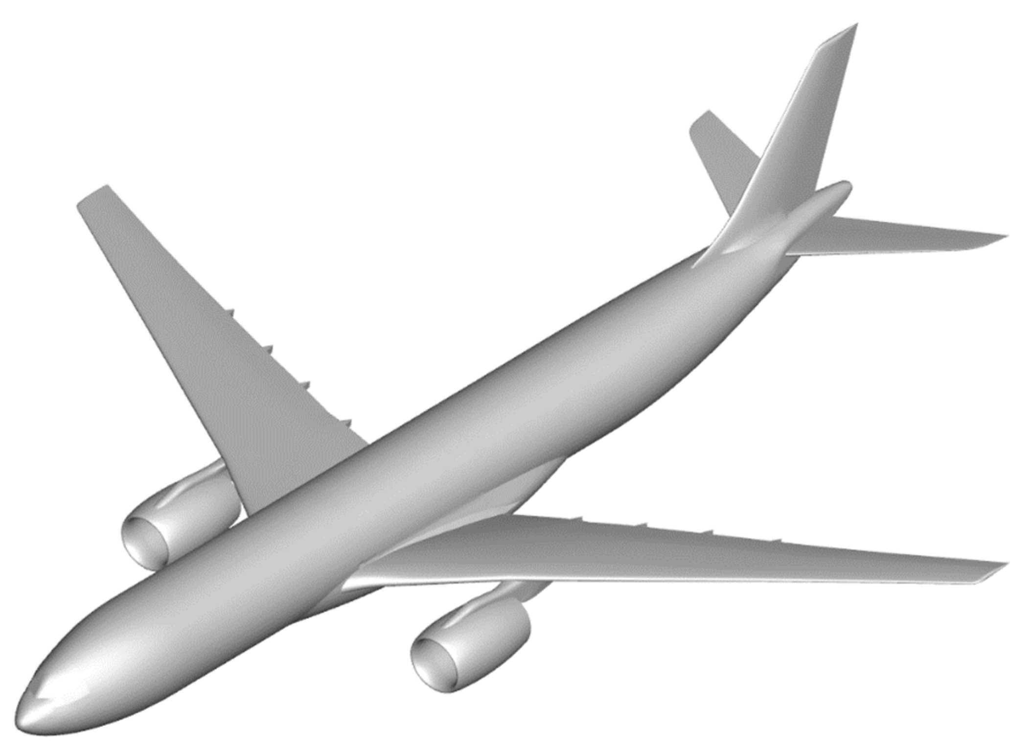
The reference aircraft used in this work is based on the XRF1-DLR-C [10]—a wide-body long range aircraft configuration with a composite wing—that is a derivate of the Airbus XRF1 (eXternal Research Forum). At DLR, the XRF1 has been investigated in various projects, among others in the DLR projects, Digital-X [11] and VicToria [12]. Figure 1 visualizes the geometry of the XRF1 configuration and Table 1 lists the global parameters used for the XRF1-DLR-C in the LuFo project Con.Move [13].
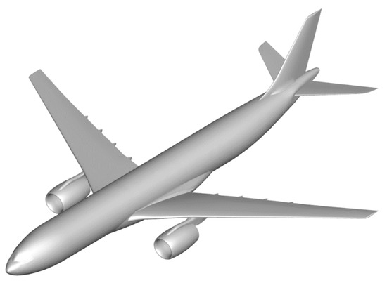
Figure 1.
Geometry of the XRF1 configuration.

Table 1.
Global parameters of the XRF1-DLR-C.
Using the in-house MONA process [14], stiffness, mass, aerodynamic and optimization models for the MSC.Nastran were generated from the cpacs (common parametric aircraft configuration schema) file. MONA stands for ModGen (an in-house model generation program) [15] and MSC.Nastran, which are the main programs used in the process. Furthermore, the structure of the lifting surfaces (skins, stringers, spars, ribs and stiffeners) was changed to a composite material that was comparable with IM7 [16] with fixed ply angle distributions. The ply angle distributions for the skins and stringers were set to bear tensile/compressive loads due to wing bending, while those of the spars and ribs were set to bear the shear loads.
2.2. Aeroservoelastic Modeling
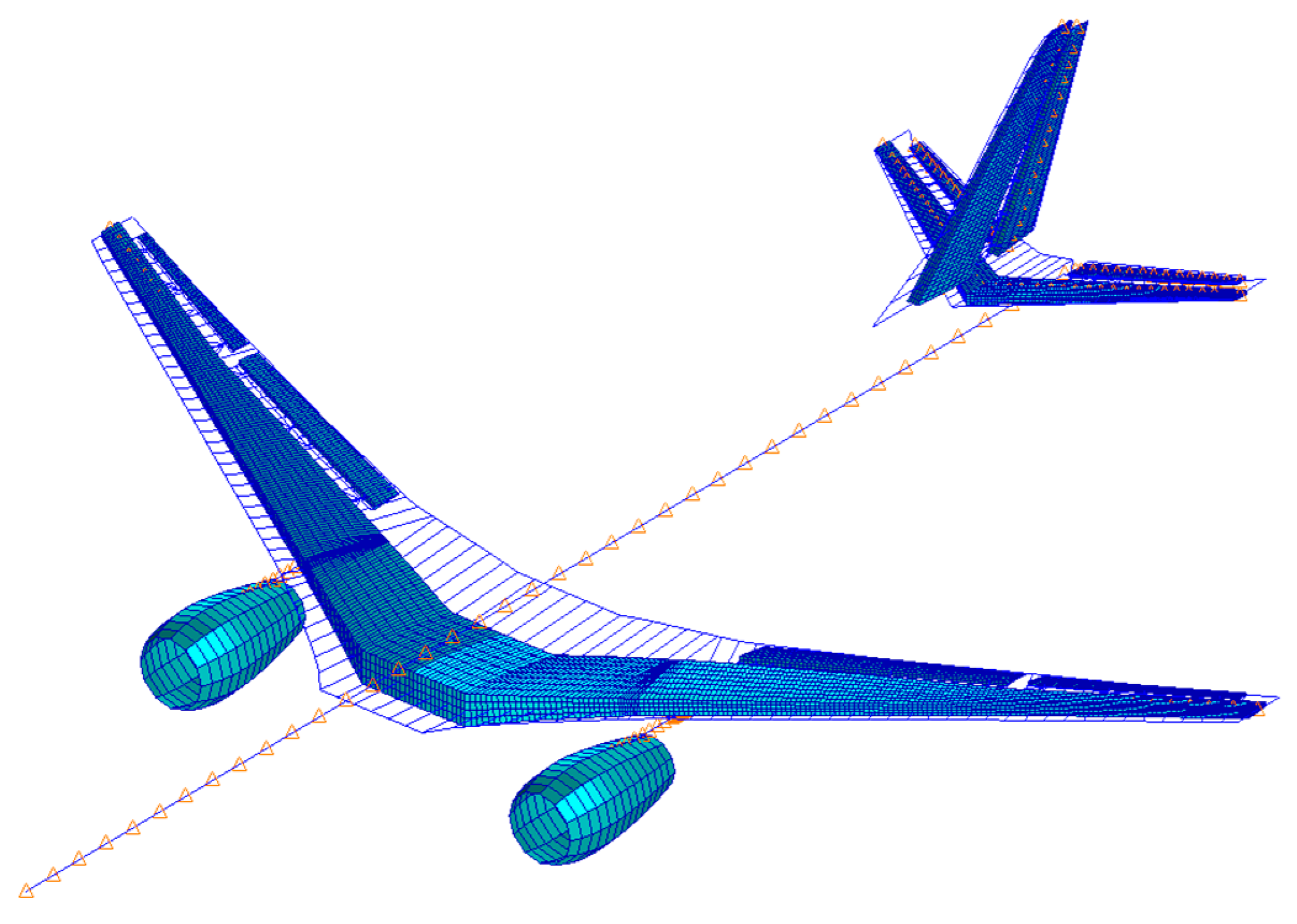
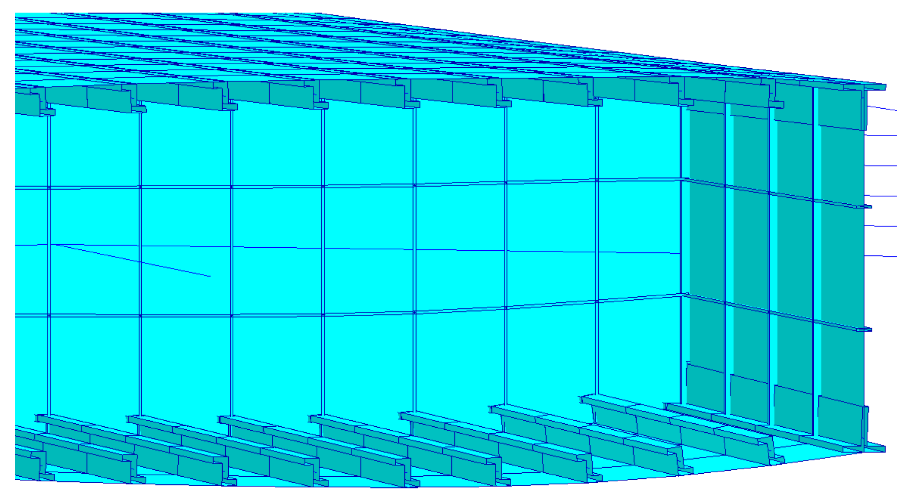
For the primary structure of the lifting surfaces, the spars, skins and ribs were modeled with shell elements, whereas the stiffeners were represented by bar elements. The fuselage was modeled with beam elements. Furthermore, the engine pylons were represented by bar elements. Figure 2 shows the MSC.Nastran global FE model of the XRF1-DLR-C where the shell elements on the engine cowling are for illustrational purposes only. All the structural elements were created using ModGen. Figure 3 shows an exemplary detail view of a wing box structure model created with ModGen. In total, the FE model had, among others, around 24,000 shell elements and 25,000 bar elements.
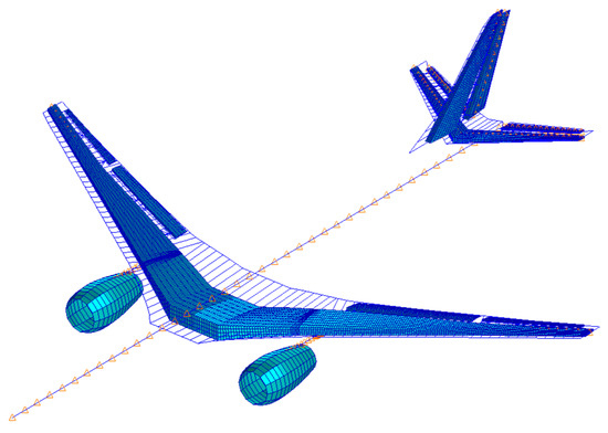
Figure 2.
Global FE model of the XRF1-DLR-C.
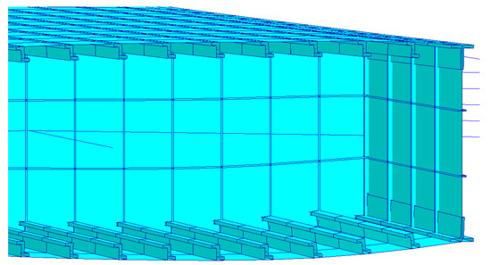
Figure 3.
Exemplary detail view of a wing box structure model.
The total mass of the aircraft model was comprised of the structural masses, secondary masses, fuel according to Klimmek [17], and the payload. The structural masses resulted from the material’s mass density of the respective shell and bar elements, whereas the remaining masses were modeled with discrete point masses with the respective rotational inertia.
With the structural masses from MSC.Nastran and the secondary masses listed in the cpacs-file, however, the target component masses—wing, HTP and VTP—were not reached yet. The target component masses resulted from mass estimations/experiences on the overall aircraft level and were also written in the cpacs-file. The discrepancies between the summarized masses and the target component masses resulted from the following:
- In the primary structure, the FE model provided an integral structure without holes, fasteners, joints, etc. All those parts require structure reinforcements which would increase the total mass of the manufactured structure. For this aspect, Chiozzotto [18] introduced the term “mass factor” in his dissertation and this aspect is addressed in Section 6.
- The mass estimation of the secondary structure is, in general, difficult since every aircraft can have, for example, unique set of systems which have unique masses. Torenbeek [19] indeed proposed mass estimation methods, among others, for leading and trailing edge devices; however, those methods do not cover all the secondary masses which are contained, for example, in the wing. Chiozzotto [18] proposed the total secondary mass estimation as a constant fraction of the maximum take-off mass which is a rough empirical approximation; however, the distribution of the secondary masses in the different aircraft components was not considered. Furthermore, the OEM also contains, among others, hydraulic fluid, lubricant and unusable fuel masses which are unique for every aircraft. At this point, it is concluded that the uncertainty in the estimation of the secondary masses is significant, and that it could cause uncertainties with respect to the target component masses.
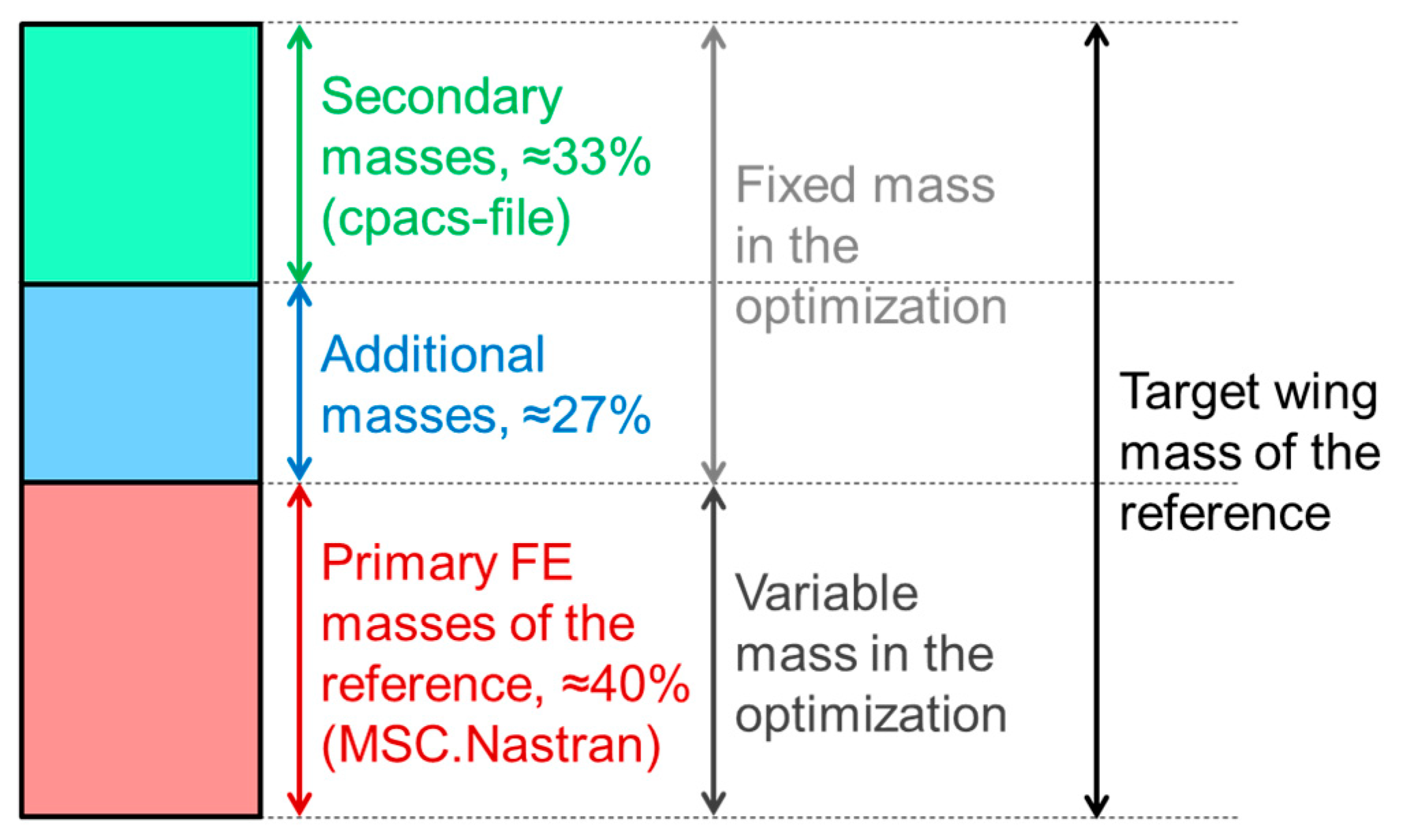
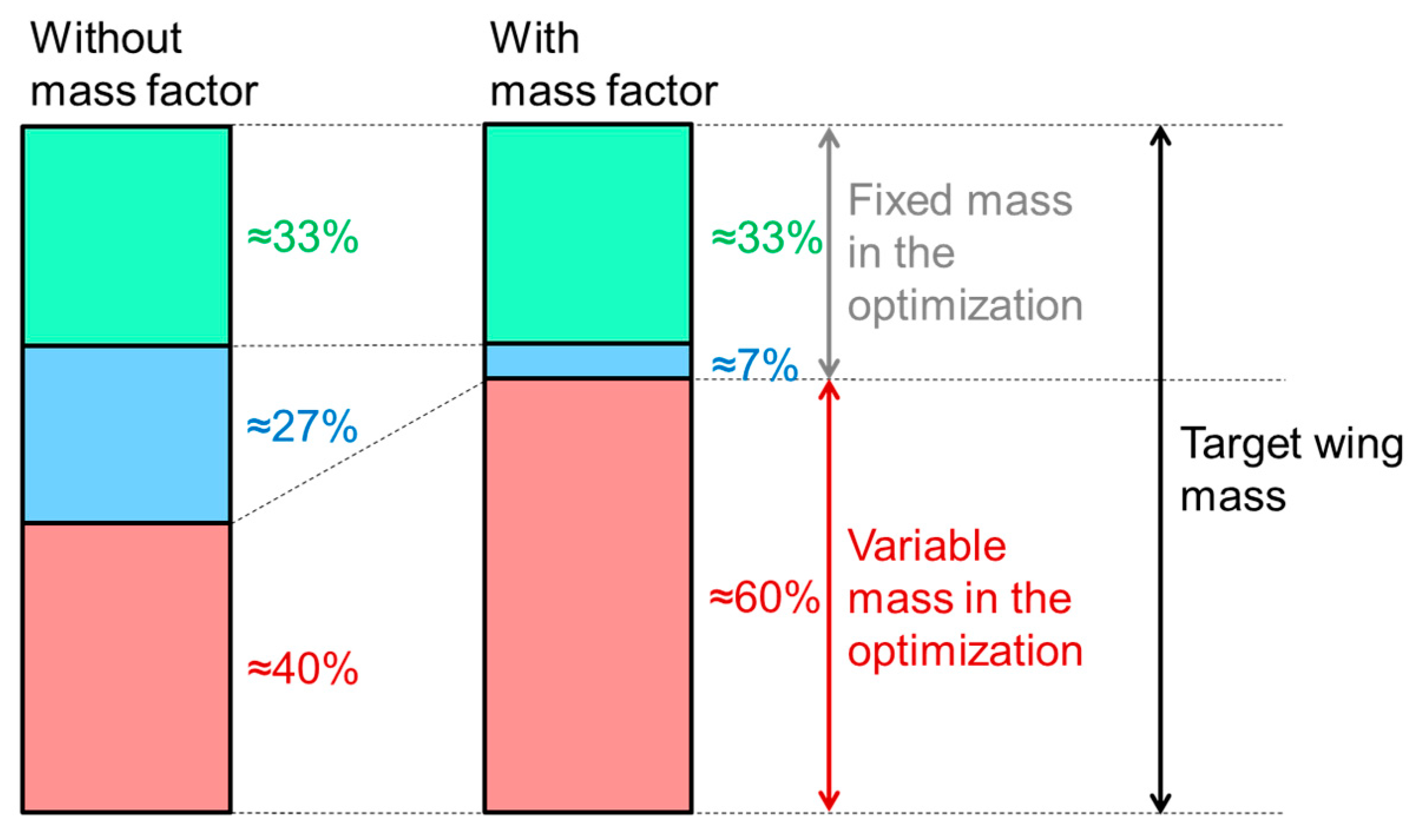
Hence, to reach the target component masses, additional masses were distributed along the span of each component. The additional masses were created using ModGen and represented a hypothetical wing box covering the whole chord length with a constant thickness; however, the masses did not necessarily stand for certain physical parts (e.g., rivets/cables/pipes) in a manufactured component. Furthermore, these additional masses were kept constant in the optimization process. Figure 4 visualizes an overview of the target wing mass as an example.
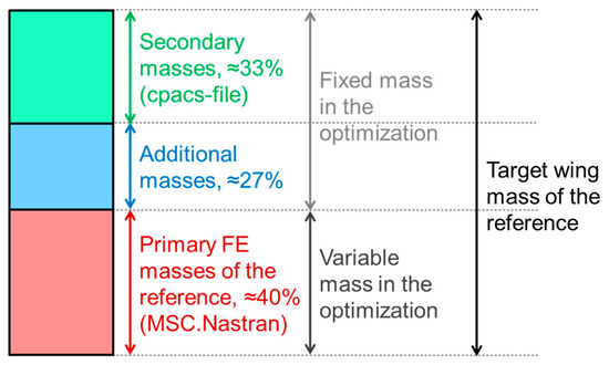
Figure 4.
Overview of the target wing mass.
Concerning the fuel masses, the fuel tanks were divided into three parts (the center, inner and outer tanks) and the defueling sequence was set to: center tank–inner tank–outer tank. This fuel distribution was relevant if the desired fuel mass was lower than the maximum total capacity. For the payload, the masses were distributed along the fuselage—between the first and the last seat row—to reach the respective target masses and center of gravity (CG) positions.
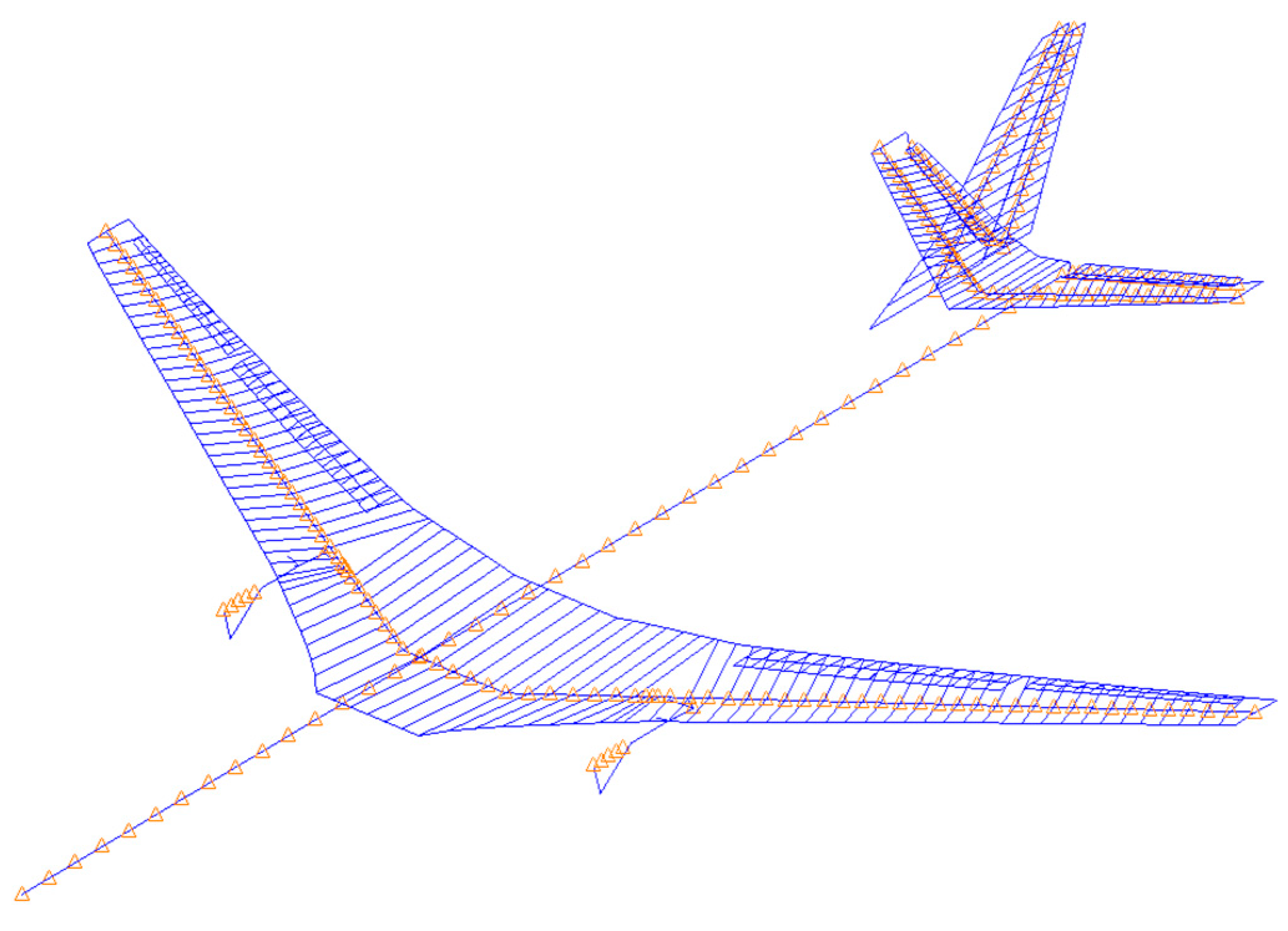
Furthermore, to reduce the computational effort in the loads analysis, the global stiffness and mass properties were condensed onto the 363 load reference axis (LRA) nodes which are indicated in Figure 5 by the orange triangles. The nodes at the leading and trailing edge of the lifting surfaces visible in Figure 5 were rigidly connected to the corresponding LRA nodes, and they served as the nodes to which the aerodynamic forces were splined onto.
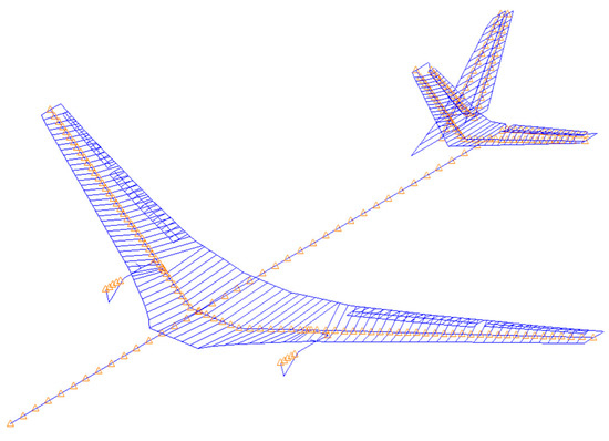
Figure 5.
Condensed FE model of the XRF1-DLR-C.
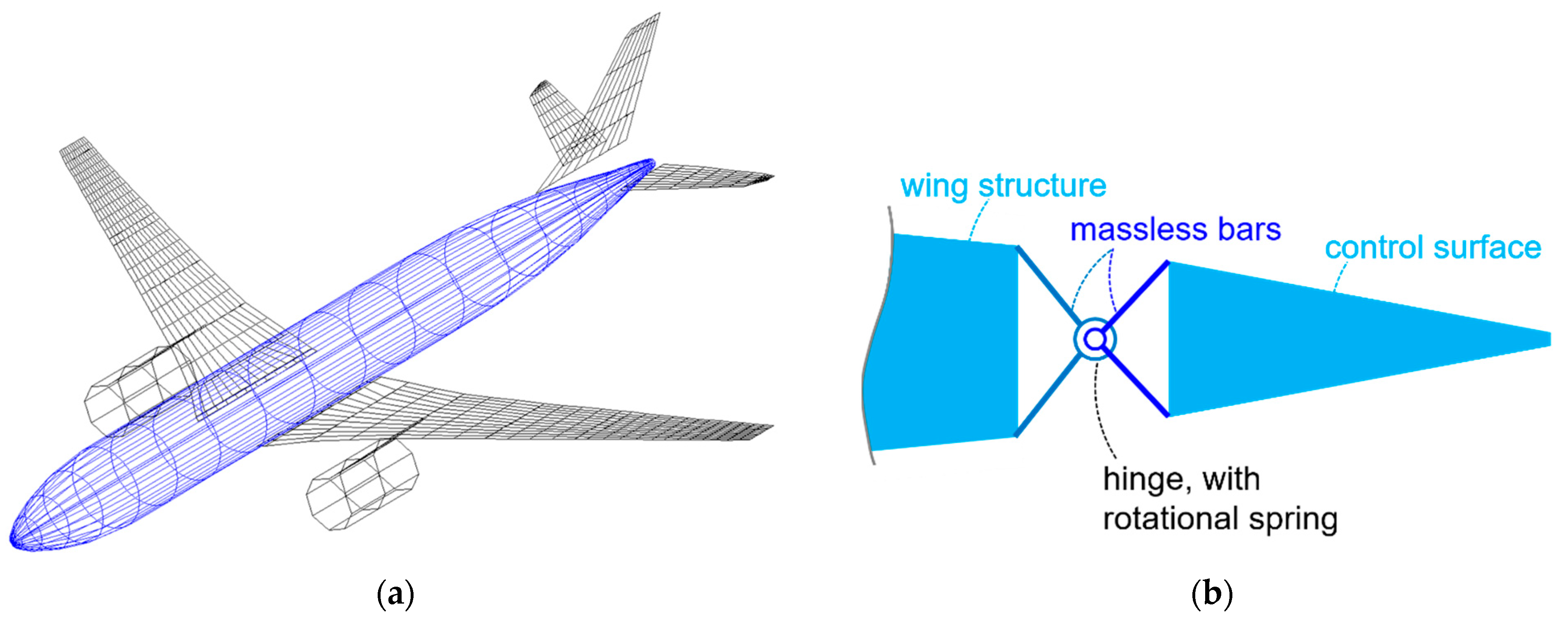
The aerodynamic forces were modeled using the doublet lattice method (DLM) [20] which is based on the potential theory. Furthermore, a slender body element and a set of interfering lifting surfaces were taken to consider the aerodynamic effect of the fuselage [21]. For the lifting surfaces, a correction for the twist and camber was taken into account. Figure 6a shows the aerodynamic model of the XRF1-DLR-C including the slender body element. In total, there were 845 aerodynamic boxes for the lifting surfaces and 80 aerodynamic elements for the slender body and its corresponding interference body.
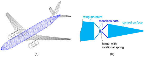
Figure 6.
Aerodynamic model of the XRF1-DLR-C (a) and principal sketch of the hinge model (b).
The structural models of the control surfaces were created using ModGen and these were connected to the wing structure using massless bar elements, while a hinge spring of 1 Nm/rad was defined to avoid a stiffness singularity. Furthermore, the corresponding DLM boxes were assigned to the control surface to reproduce its deflection, and the aerodynamic effectiveness was set to 1.0. Figure 6b shows a principal sketch of the hinge.
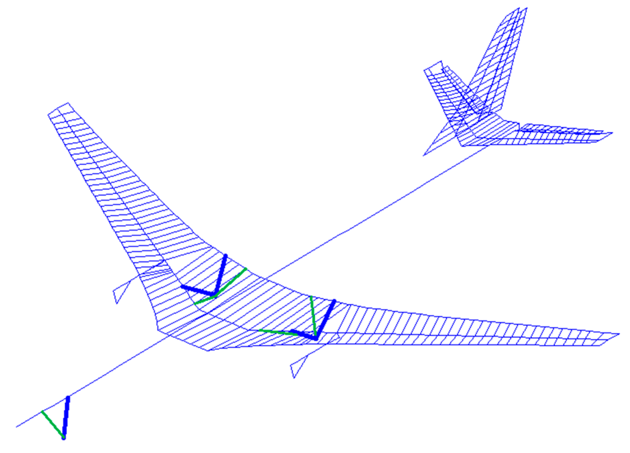
For the introduction of the landing gear loads, a simplified model using massless bars was applied. The massless bars connected the nodes which represent the tire positions and nodes on the aircraft. For the nose gear, the bar representing the main strut was connected to the nearest fuselage node, while the bar representing the side stay was connected to a fuselage node further forward. For the main gear, the main strut was represented by two bars which connected the landing gear node with the nearest wing LRA and the corresponding trailing edge node, respectively. This was completed to enable a transfer of the torsion moments from the landing gear into the wing since the bar elements in MSC.Nastran are not designed to transfer moments. Analogously, the side stay was modeled with two bars which were connected to an LRA and its corresponding trailing edge node further inboard. The bar elements for the main strut were set to a stiffness equivalent to an aluminum rod with a 10 cm diameter, while those for the side stay had an equivalent rod diameter of 5 cm. Figure 7 visualizes the simplified landing gear modeling; the blue bars represent the main struts, and the green ones stand for the side stays.
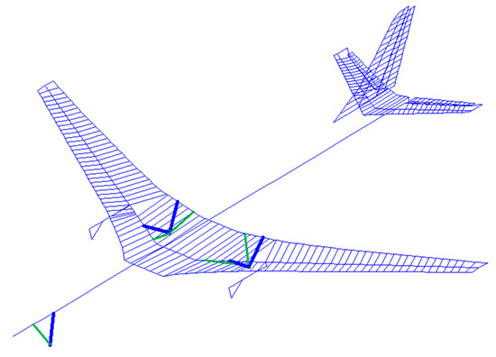
Figure 7.
Simplified landing gear modeling on the XRF1-DLR-C.
3. Design Process with Loads Analysis and Structural Optimization
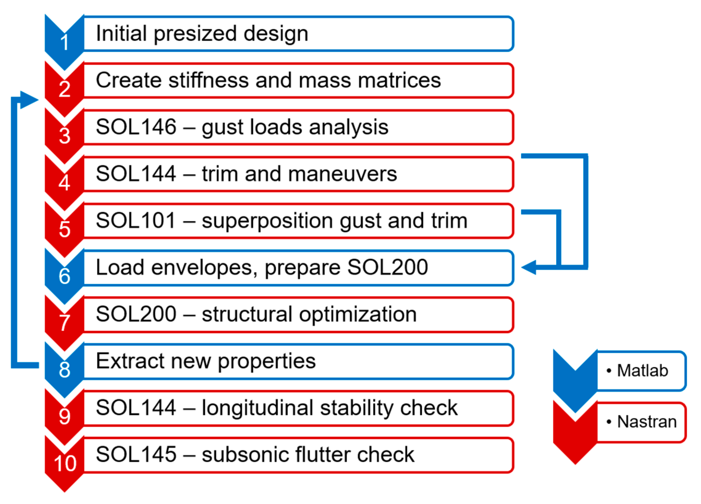
The design process for the investigation of the load alleviation is based on the MONA process [14] and mainly consists of an iterative cycle of loads analysis and structural optimization. Both steps are run iteratively since they cannot always be conducted simultaneously, e.g., when dynamic simulations are considered. Furthermore, the loads and the structural properties on an elastic aircraft depend on each other, thus, an information feedback between both aspects is necessary.
In doing so, the initial input was a pre-sized design from the model generator ModGen [15] which is a program in the MONA process. The global stiffness and mass properties were then condensed to reduce the computational effort in the gust, trim and maneuver simulations in MSC.Nastran.
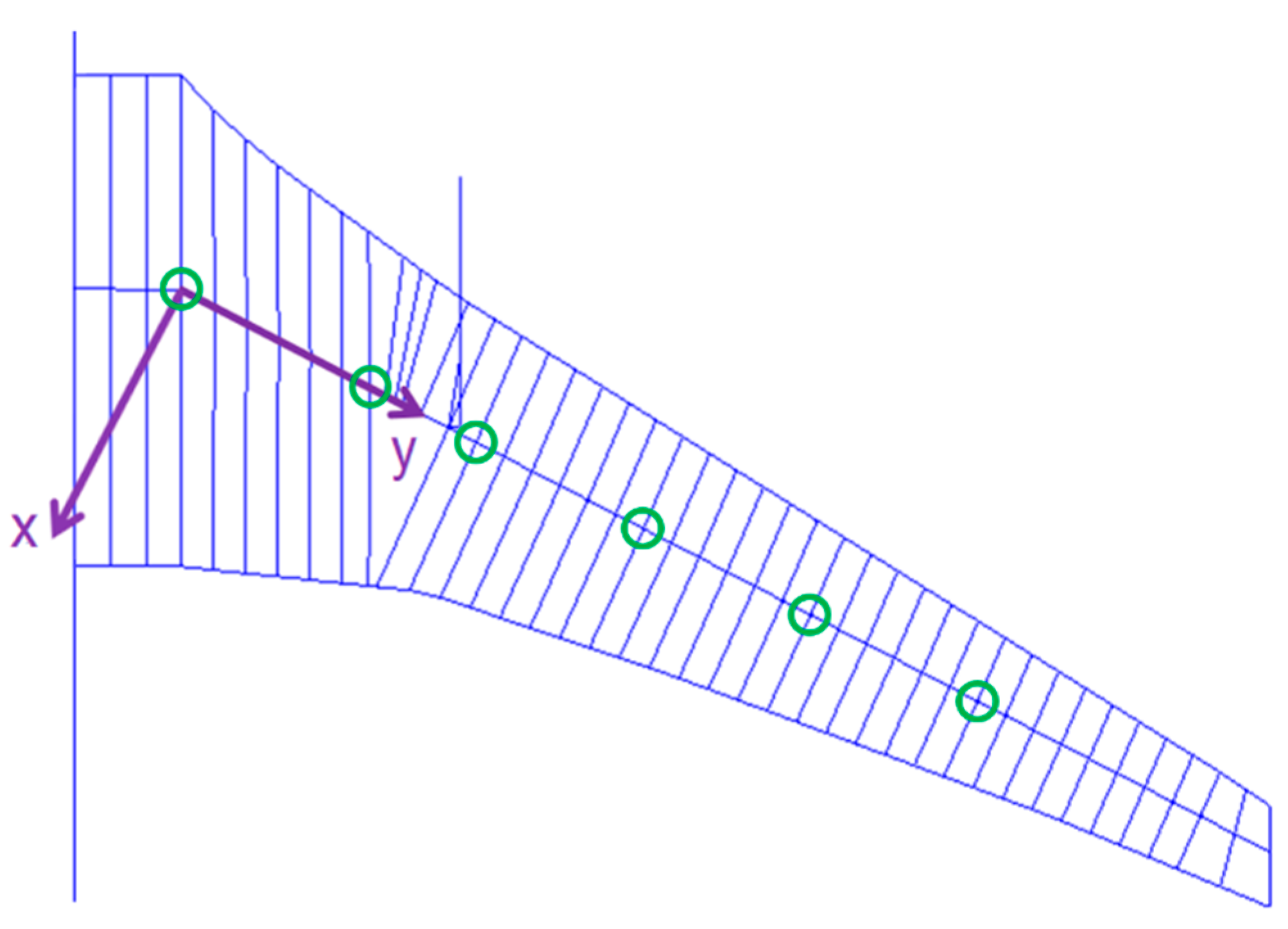
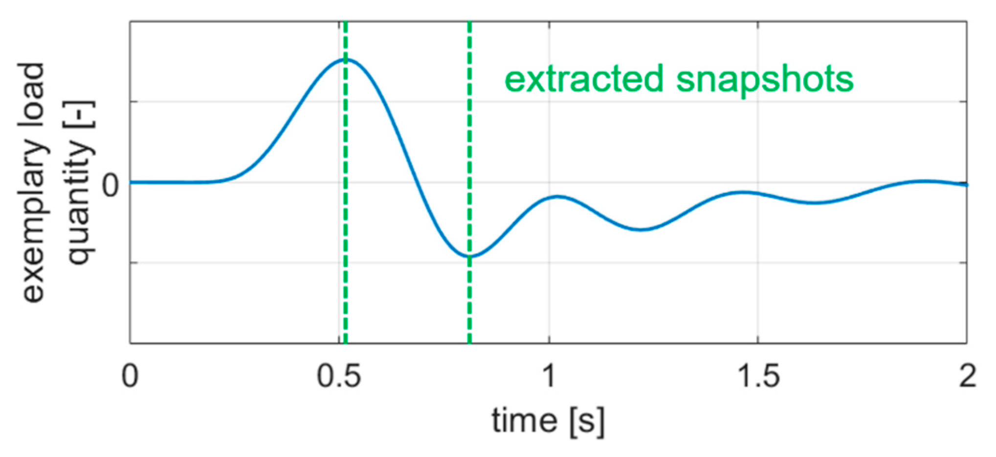
The dynamic gust simulations were conducted using the solution sequence SOL146 of MSC.Nastran, which is a frequency domain method with DLM aerodynamics. To reduce the amount of data that was processed, a first step of the load filtering was carried out after the gust simulations. To do so, six monitoring stations for cut loads were generated along the wing span as shown by the green markers in Figure 8, and the cut loads were calculated in the indicated local coordinate system. It is important to note that for the visualization in Section 5, the cut loads were calculated at every second node. In the gust simulations, the shear force , bending moment and torsion moment were monitored, and each time one of those quantities reached its maximum or minimum, all the nodal loads at that time step were extracted. Figure 9 illustrates the extraction exemplarily.
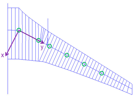
Figure 8.
Monitoring stations and the local coordinate system on the starboard wing.
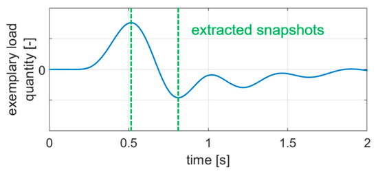
Figure 9.
Extracted snapshots from a gust encounter.
The quasi-steady trim and maneuver simulations were carried out with SOL144 of MSC.Nastran. Since the gust simulations yield incremental loads only [21], they have to be superposed with the corresponding 1 g trim loads. In this case, it was carried out using SOL101.
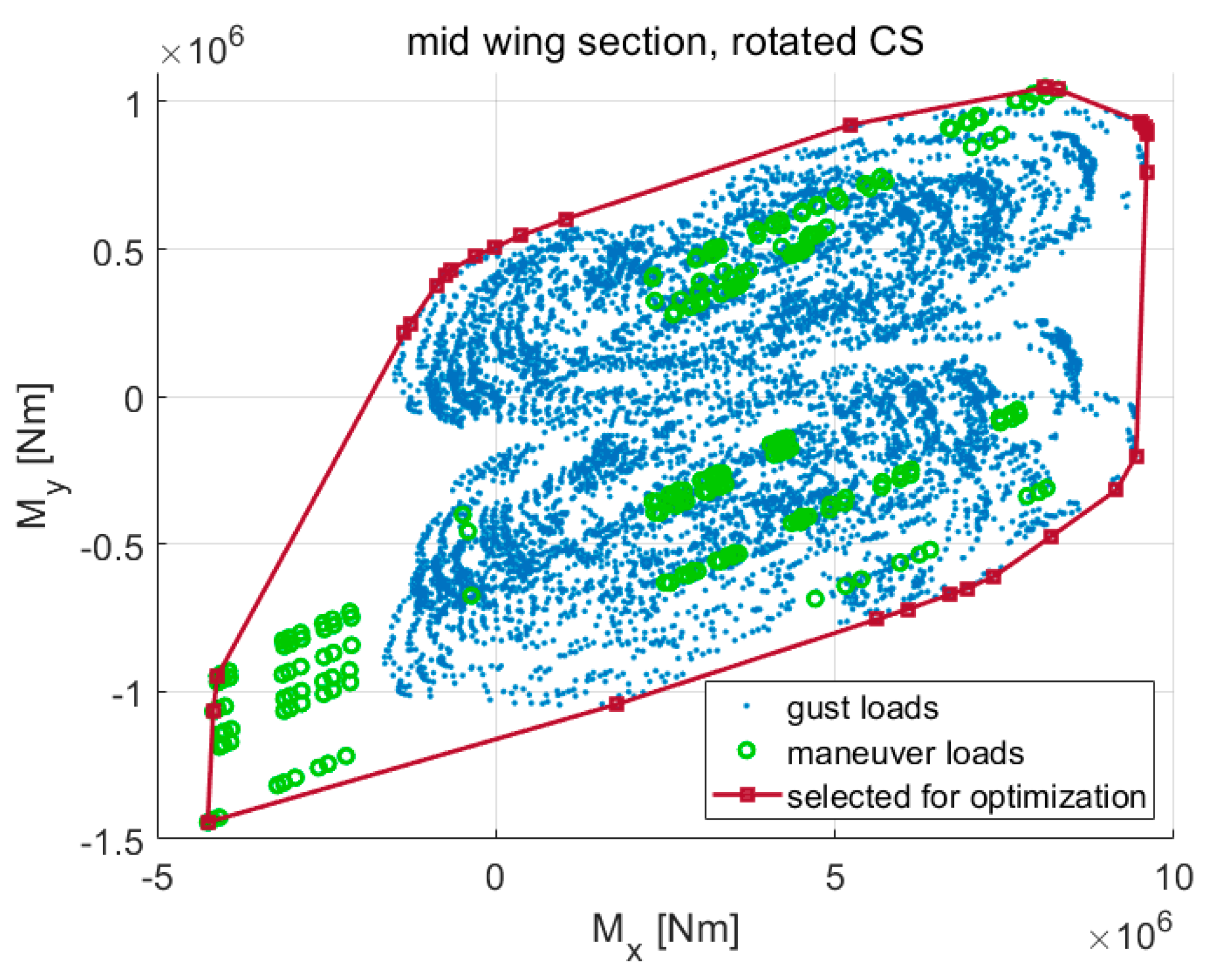
Subsequently, the loads resulting from quasi-steady maneuver and dynamic gust cases were filtered in a second step before they were inputted into the structural optimization [22]. To do so, 2D envelopes of the cut loads were generated at the six monitoring stations with the combination of the load components / (see Figure 10) and /. The load cases appearing on the edges of the 2D envelopes were selected for the structural optimization. By doing so, the number of considered load cases was reduced from a few thousands to below one hundred. Beside those flight loads, a simplified, quasi-steady, symmetric landing case with a load factor of 1.5 was considered.
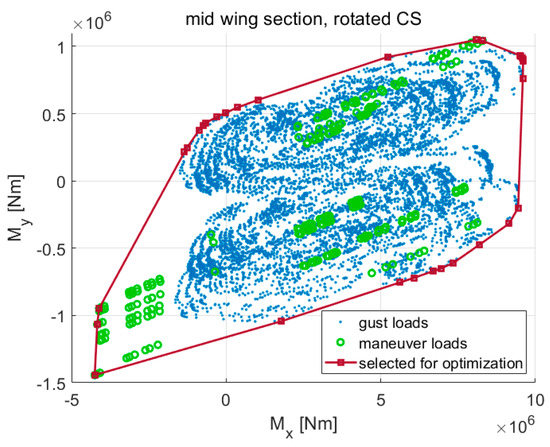
Figure 10.
2D envelope surrounding gust and maneuver loads.
In the structural optimization, the objective lay in minimizing the structural mass while complying with structural constraints (max. strain, buckling and minimum thickness). For the strains, the allowable for the ultimate loads was 4000 µ in the major principal strain, −3500 µ in the minor principal strain and 8000 µ in the maximum shear. The buckling analysis was based on the method used by Klimmek [17] with the equation by Tetlow [23], where a two-dimensional buckling of a composite plate under compressive stress is assumed. In this case, the buckling field was assumed as an infinitely long plate with a 250 mm width, which represents the average distance between two stringers. In doing so, the minor principal stress was considered in the buckling analysis. The design variables comprised the material thicknesses of the design fields on the wing box. The general mathematical formulation of the optimization task is:
with the objective function , the design variables , the optimization constraints and the boundaries of the design variables , and .
The steps of the loads analysis and structural optimization were conducted iteratively until a structural mass convergence of approx. 0.1% between two cycles was reached [22]. Subsequently, a check of the flight mechanical longitudinal stability was carried out. The flight mechanics could become unstable due to the following reason: if the wing becomes more flexible, the aerodynamic center is shifted forward since the outer part of the wing—which lies further backward—becomes less effective due to the wing elasticity and the bending-torsion-coupling. If the shift of the aerodynamic center is large enough, it can move in front of the CG which makes the aircraft naturally unstable. Furthermore, a subsonic flutter check using the KE-method with MSC.Nastran was performed. Figure 11 shows a flowchart of the design process, and ‘SOL’ stands for the respective solution sequence in MSC.Nastran.
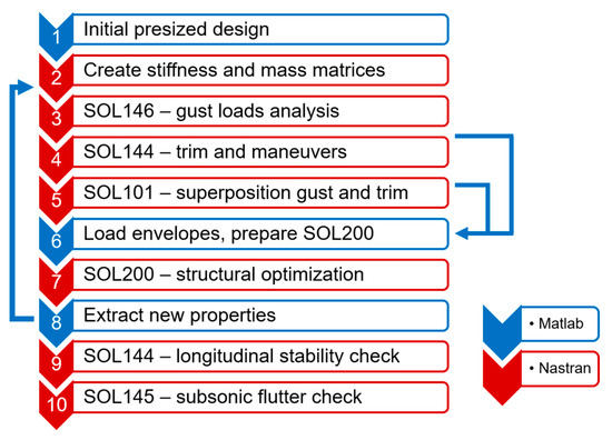
Figure 11.
Workflow of loads analysis and structural optimization.
4. Modeling of Load Alleviation Systems
The objective of the implemented load alleviation functions mainly lay in reducing the wing bending moment. Since the highest wing bending moments typically occur during pull-up maneuvers, a maneuver load alleviation (MLA) was implemented in the design process addressed in Section 3. In this case, the control surfaces and the spoilers were deflected symmetrically during the maneuvers. The detailed control surface assignment and algorithm for the MLA are elaborated further in Section 5. In the aerodynamic model, the spoiler deflection was modeled by a trailing edge control surface deflection with a correction factor for the area ratio and an assumed aerodynamic effectiveness of 0.75. Figure 12 shows a principal sketch of the MLA function: by deflecting the outer control surfaces, the lift distribution is shifted toward the wing root, and the root bending moment is reduced, while the root shear force is at a relatively constant level.

Figure 12.
Change of spanwise lift distribution with MLA.
With MLA, however, the maneuver loads might become lower than the gust loads. To reduce the gust loads, a feed-forward gust load alleviation (GLA) algorithm was implemented in the design process as well. Figure 13 shows the block diagram of the GLA algorithm.

Figure 13.
Block diagram of the GLA algorithm.
During a gust encounter, the gust angle of attack is assumed to be detected at the aircraft nose, and the assigned control surfaces are deflected symmetrically with a proportionality factor to counteract the incremental lift due to the gust. The selection of the gain was based on a potential theoretical modeling by Schlichting/Truckenbrodt [24] and is described in more detail in the results section. Moreover, several filters (low pass, high pass and delay) and a time domain rate limiter were added to the algorithm. The low pass filter was intended to avoid excessively high control surface deflection rates, and the high pass filter was implemented to avoid having non-zero control surface deflections in a constant wind field (at zero frequency). The time delay was considered to represent the elapsed time between the gust detection at the nose and the gust hitting the wing.
Hence, the transfer function of the GLA was:
At this point, the term, commanded deflection , means that the time domain rate limiter has not been applied yet. In this case, the rate limit was set at 100°/s and the actual control surface deflection was obtained after applying the rate limiter. The GLA control surface assignment and gain are described for each control surface layout in Section 5.
5. Loads and Mass Results of Test Cases
This section starts with the parameter space used in the design process comprising the mass configurations, flight conditions, load case scenarios and optimization constraints. Subsequently, the results of the test cases are elaborated and include:
- The reference variant which incorporates the maneuver load alleviation (MLA).
- Passive variant. The term passive means that MLA is inactive. This test case was intended to provide an insight into how much mass reduction is already achieved by MLA.
- Maneuver and gust load alleviation (MLA + GLA). This corresponds to the reference with an additional GLA function.
- MLA + GLA, enhanced control surface layout and MLA/GLA algorithms (enh. MLA + GLA). While the previous test case used the available control surfaces only, this case featured load alleviation with additional control surfaces.
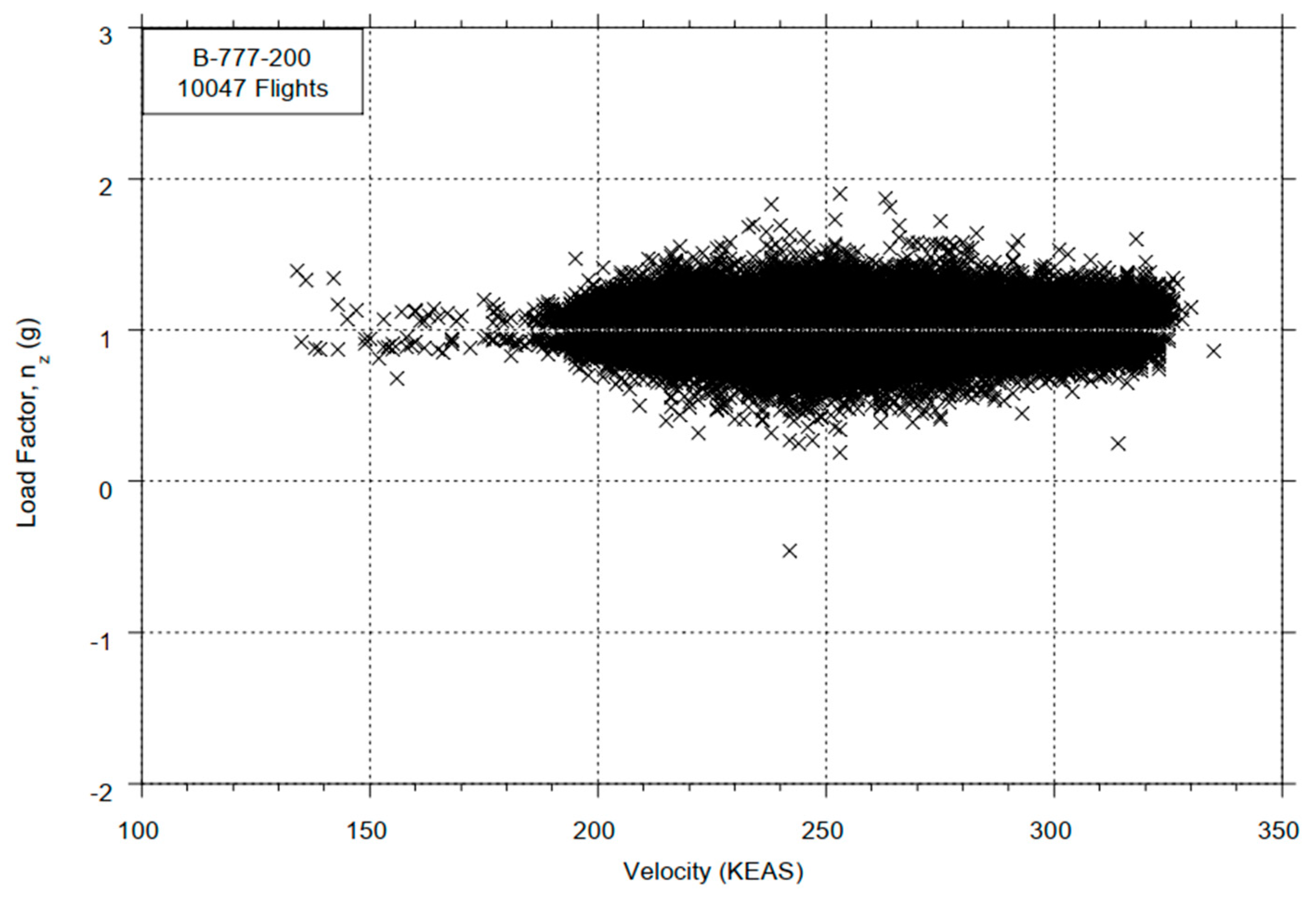
- MLA + GLA, enhanced control surface layout, MLA/GLA algorithms and reduced design load factor (red. load factor). According to the statistical loads data of the Boeing 777-200ER [25], load factors above 1.5 were hardly reached during the surveyed 10,000 flights; therefore, while assuming that the technologies will improve, the maximum design load factor was reduced from 2.5 to 1.5 and the design gust speeds were halved.
- MLA + GLA, enhanced control surface layout, MLA/GLA algorithms, reduced design load factor and reduced safety factor (red. safety factor). With an assumption of a more accurate tolerance in the materials, the safety factor was reduced from 1.5 to 1.3.
Additionally, a wing box with a minimum thickness was featured to show the influence of manufacturing and operational constraints on the structural mass. It is important to mention that this wing box could not withstand a 1 g loading.
Subsequently, an overview of the load results as well as the aeroelastic parameters (longitudinal stability and subsonic flutter check) is shown in Section 5.9.
As stated in Section 1, the mass changes only resulted from the primary structure without further snowball effects.
5.1. Parameter Space
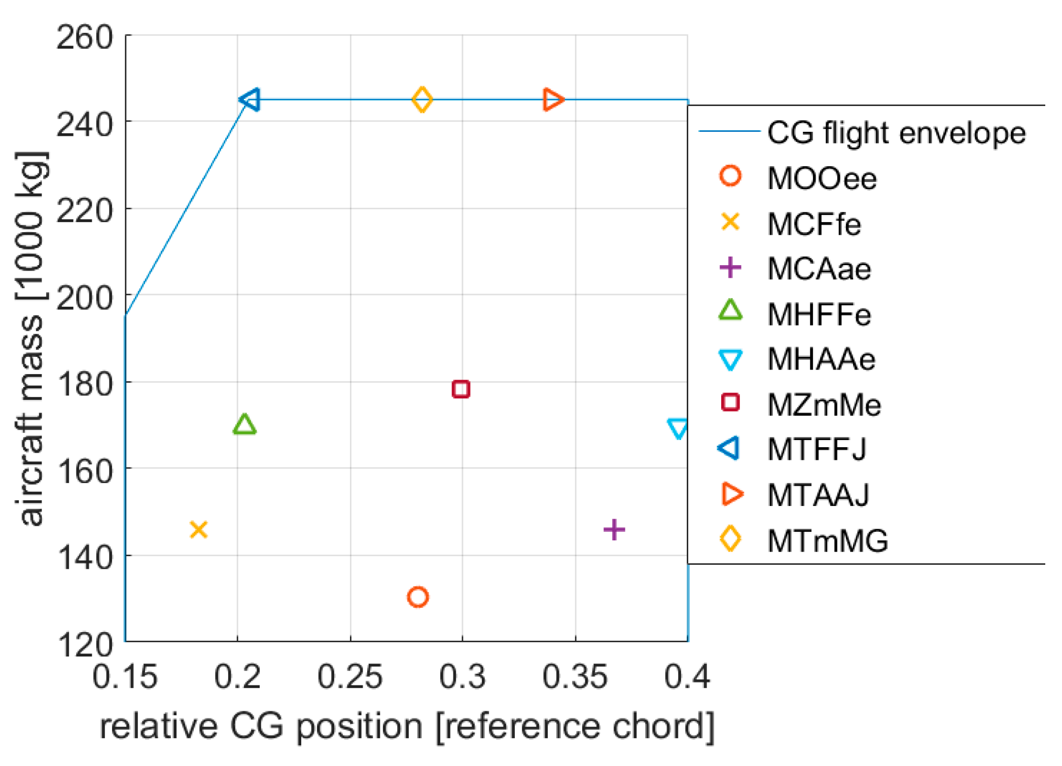
In the loads analysis, a total of nine mass configurations ranging from the operating empty mass (OEM) to the maximum takeoff mass (MTOM), with a wide range of center of gravity (CG) positions—relative to the reference chord/mean aerodynamic chord—were considered as shown in Figure 14. The labels for each mass case are listed in Table A1 in the Appendix A.
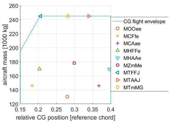
Figure 14.
Overview of the mass configurations.
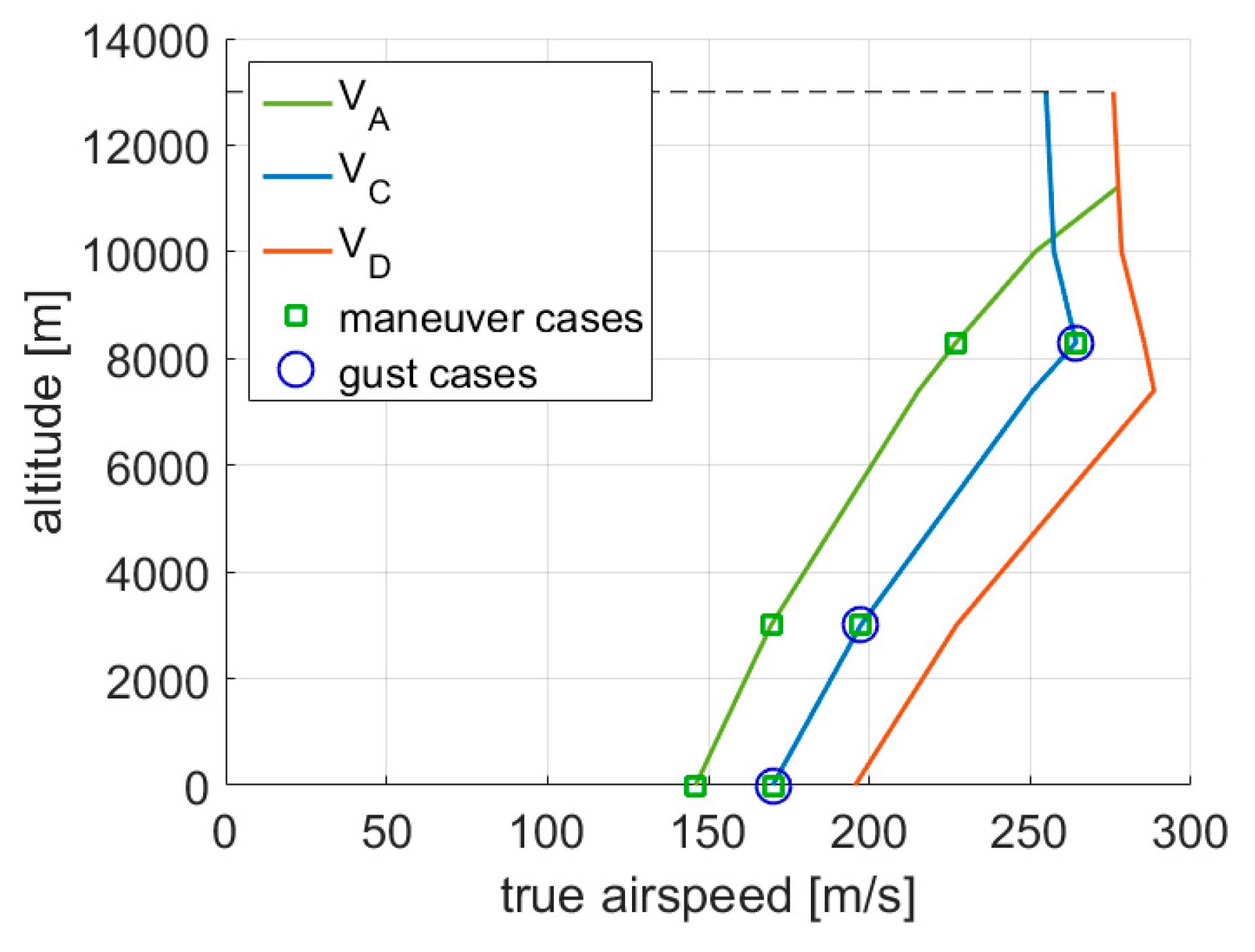
Concerning the flight conditions, the altitudes between sea level and approx. 8300 m were considered. The latter is the altitude where the design cruise speed is reached simultaneously as the design cruise Mach number . In the mentioned altitude range, the largest loads typically emerge [26]. The airspeeds taken into account in the maneuver simulations were the design maneuver speed and design cruise speed , whereas the gust encounters were calculated at as illustrated in Figure 15. The design maneuver speed was assumed to equal the minimum dynamic pressure to conduct a 2.5 g pull-up maneuver at MTOM with a maximum lift coefficient of 1.3.
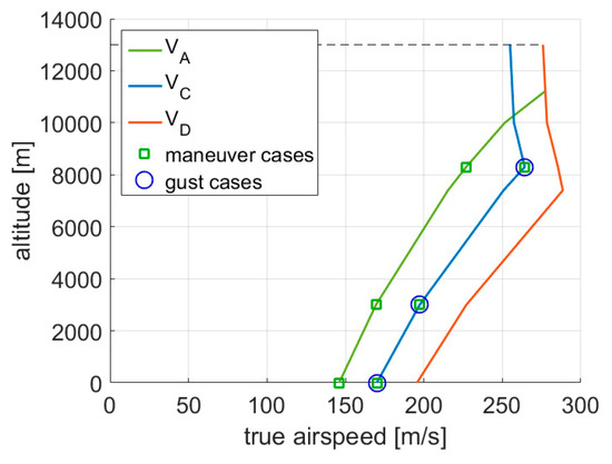
Figure 15.
Selected flight conditions in the design envelope.
The design dive speed was not taken into account to exclude load cases at too high Mach numbers, in this case at the design dive Mach number . This was, among others, because the control surfaces deflection amplitudes had to be reduced since buffeting might have emerged. On one hand, this case could not be assessed using DLM aerodynamics. On the other hand, with the reduced control surface deflection amplitudes, the load alleviation effect would have also decreased, and the mass benefit through a load alleviation would not have been as clearly visible.
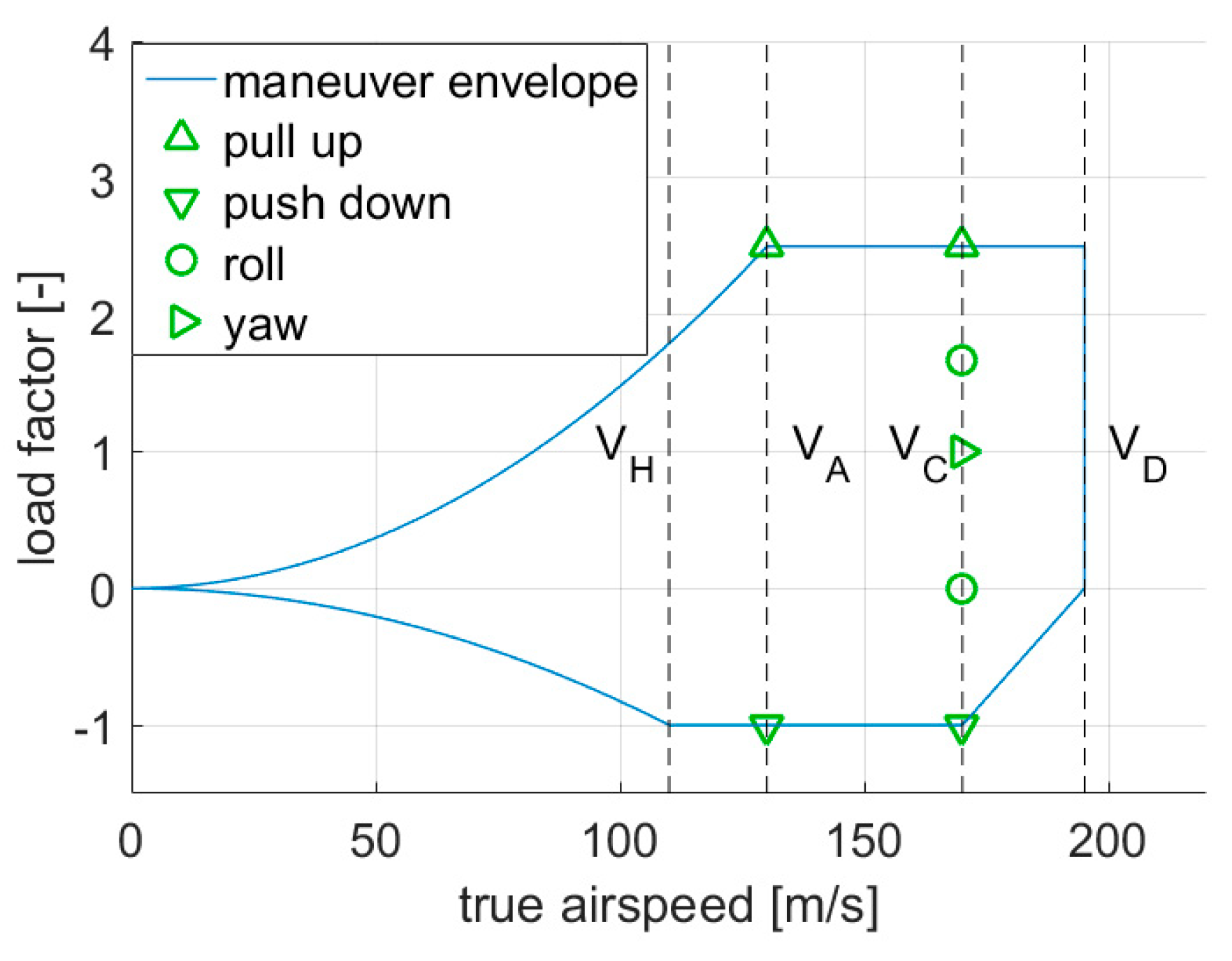
The maneuvers considered in the simulations were based on CS25 [27] and comprised:
- 2.5 g pull-up at and ,
- −1.0 g push-down at and ,
- Steady roll at 0 g and 1.67 with a roll velocity of 15°/s, at ,
- Accelerated yaw maneuver with a 5° rudder angle at .
Figure 16 shows the considered maneuver cases in an exemplary V-n diagram. With nine mass configurations, three flight altitudes and seven maneuvers each, a total of 189 maneuver cases were considered.
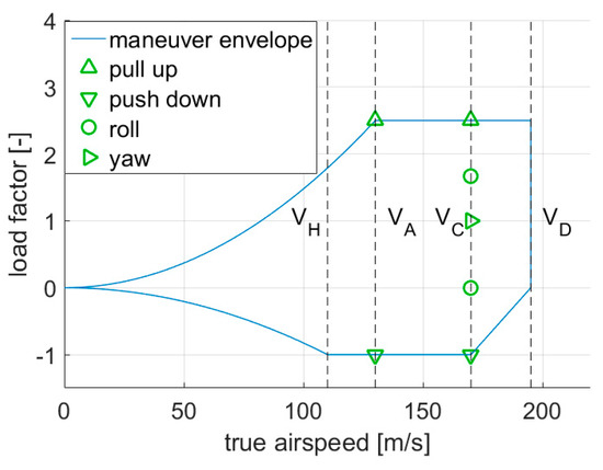
Figure 16.
Considered maneuver cases in an exemplary V-n diagram.
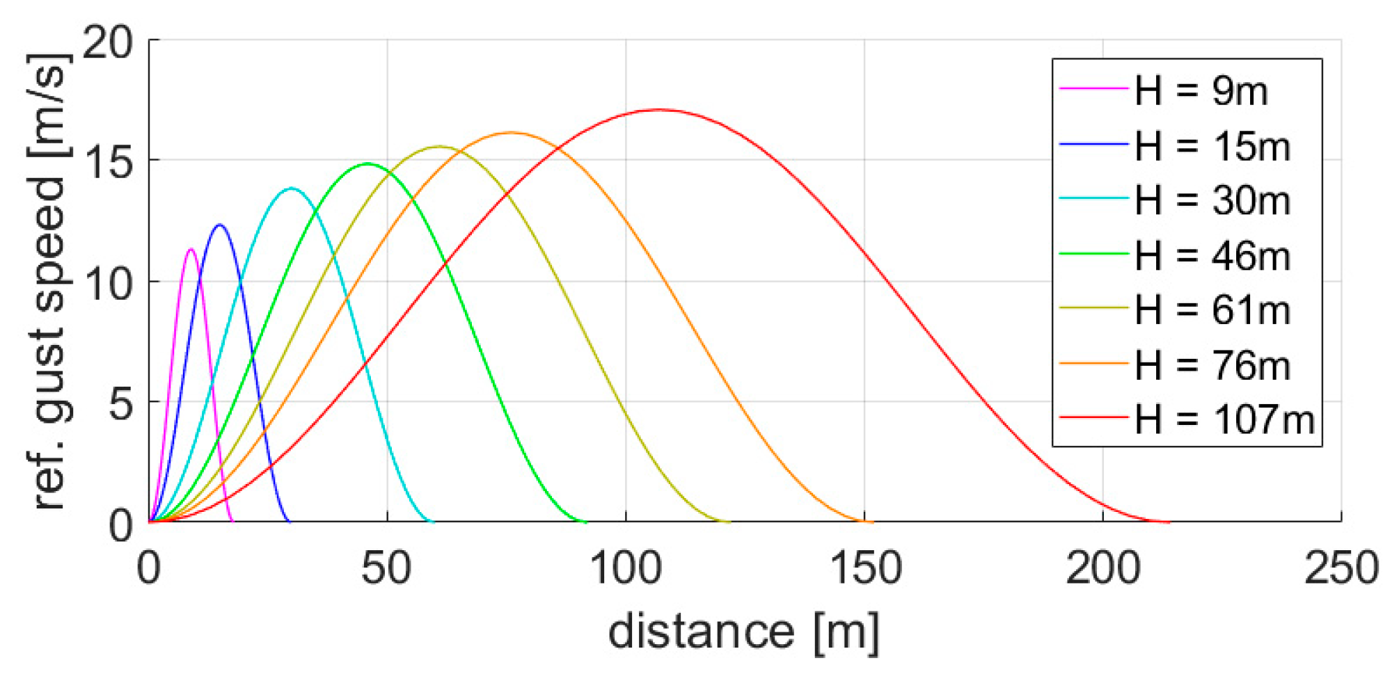
The 1-cos dynamic gust cases were also based on CS25 [27], with seven gust gradients ranging from 9 m to 107 m (30 ft to 350 ft), and the following scenarios were considered:
- Vertical upward and downward gusts on the clean configuration at ,
- Vertical upward and downward gusts with airbrakes out (flight spoilers were deflected by 30°) at .
Figure 17 visualizes the 1-cos gust profiles with the seven different gust gradients. With nine mass configurations, three flight conditions, seven gust gradients, two gust directions and two airbrake configurations, a total of 756 gust cases were taken into account.
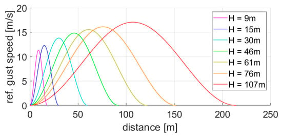
Figure 17.
Overview of the 1-cos gust profiles.
5.2. Reference with MLA
For the reference variant, the MLA was scheduled as following:
- During 2.5 g pull-up maneuvers, the inner, outer ailerons and the outer three spoilers were deflected by −20° (trailing edge up).
- During −1 g push-down maneuvers, the control surfaces were not deflected.
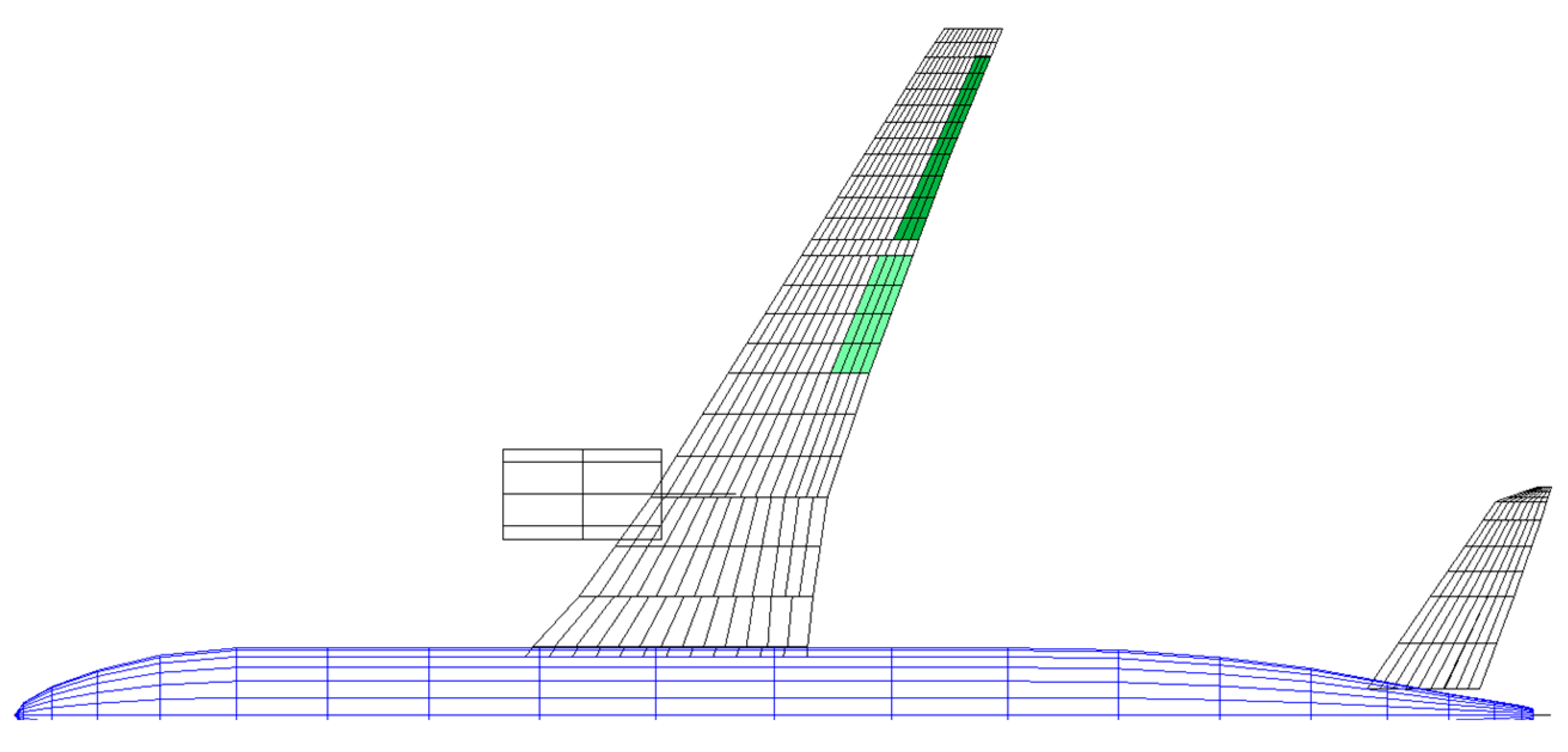
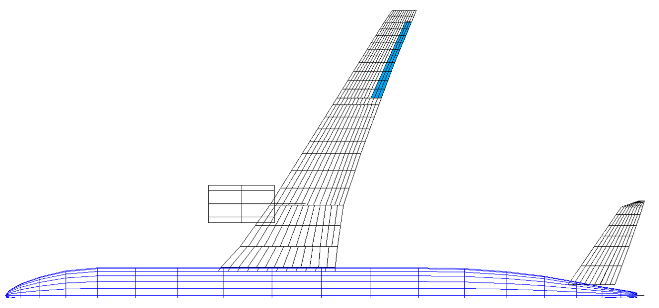
Figure 18 visualizes the control surfaces which were deflected by MLA. As mentioned in Section 4, the spoiler deflection was represented by a trailing edge control surface deflection with a correction factor for the area ratio and an assumed aerodynamic effectiveness of 0.75. This yielded a smaller trailing edge control surface deflection at the spoiler position, and, therefore, the corresponding aerodynamic boxes are highlighted with a lighter color. The usage of the trailing edge control surface to model a spoiler deflection potentially yielded a less accurate torsion moment compared to deflecting the actual aerodynamic elements which coincides with the spoilers. The latter aspect, however, required more time and effort in adjusting the aerodynamic model.
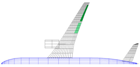
Figure 18.
Deflected control surfaces using the reference MLA algorithm.
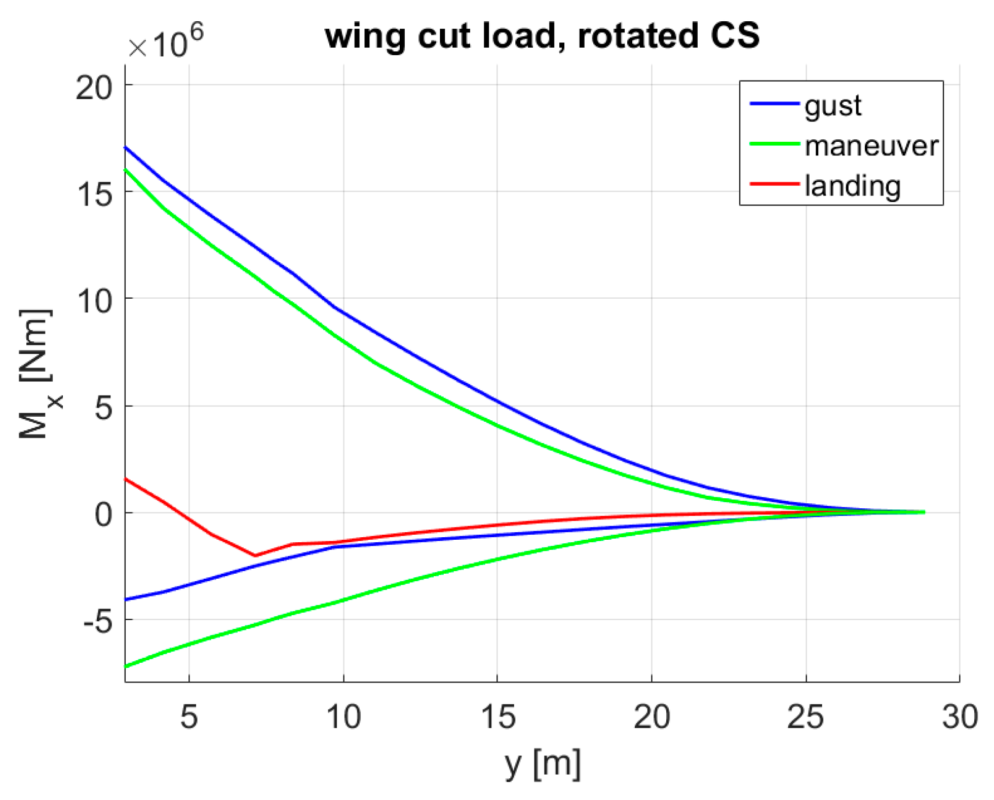
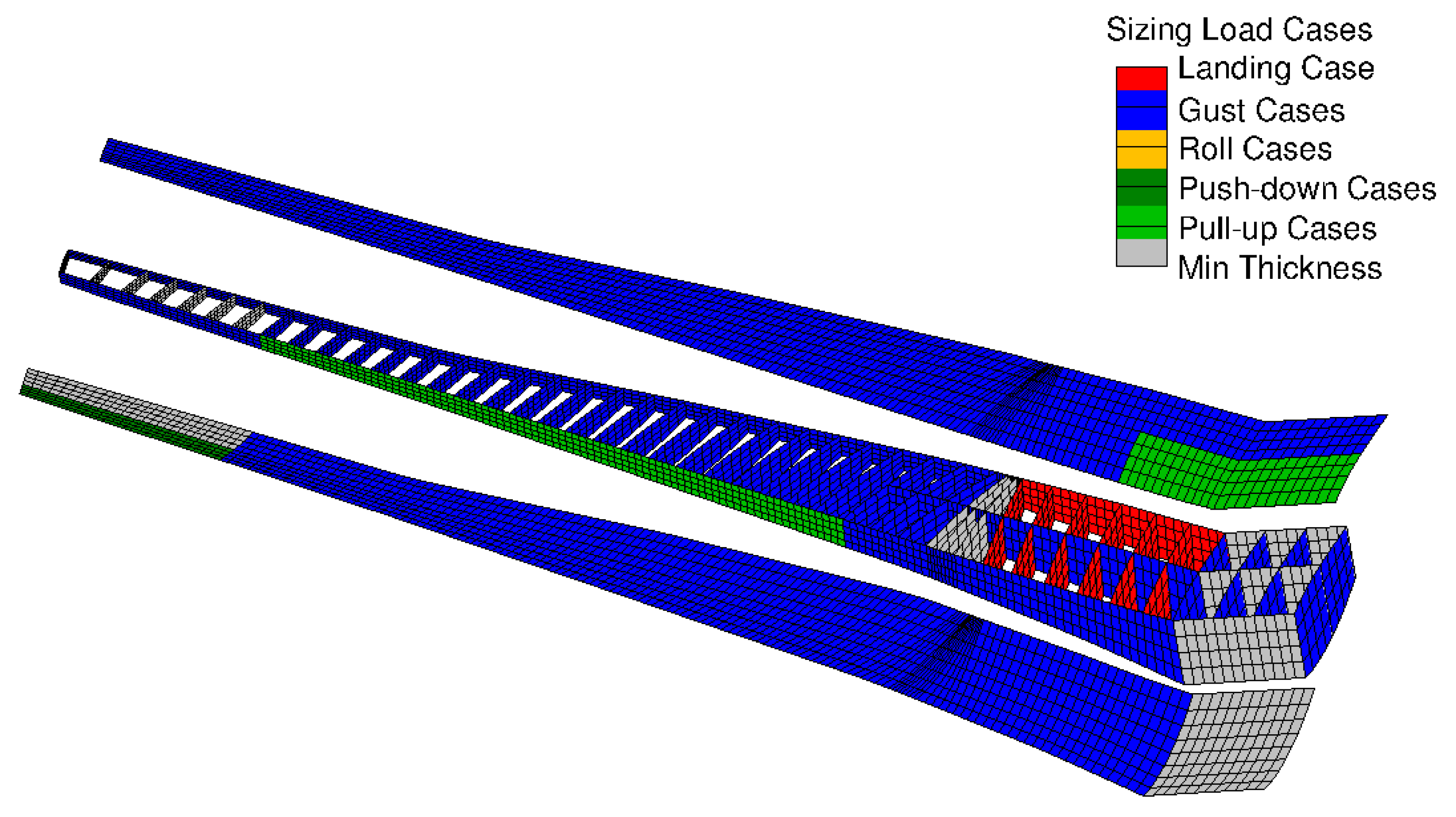
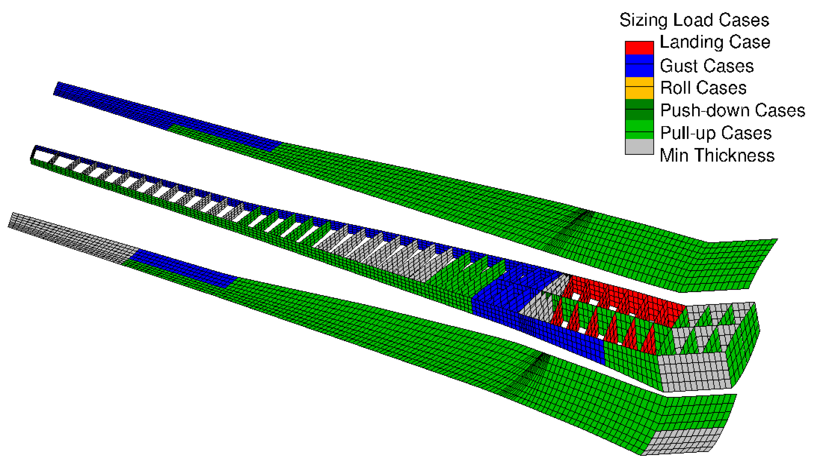
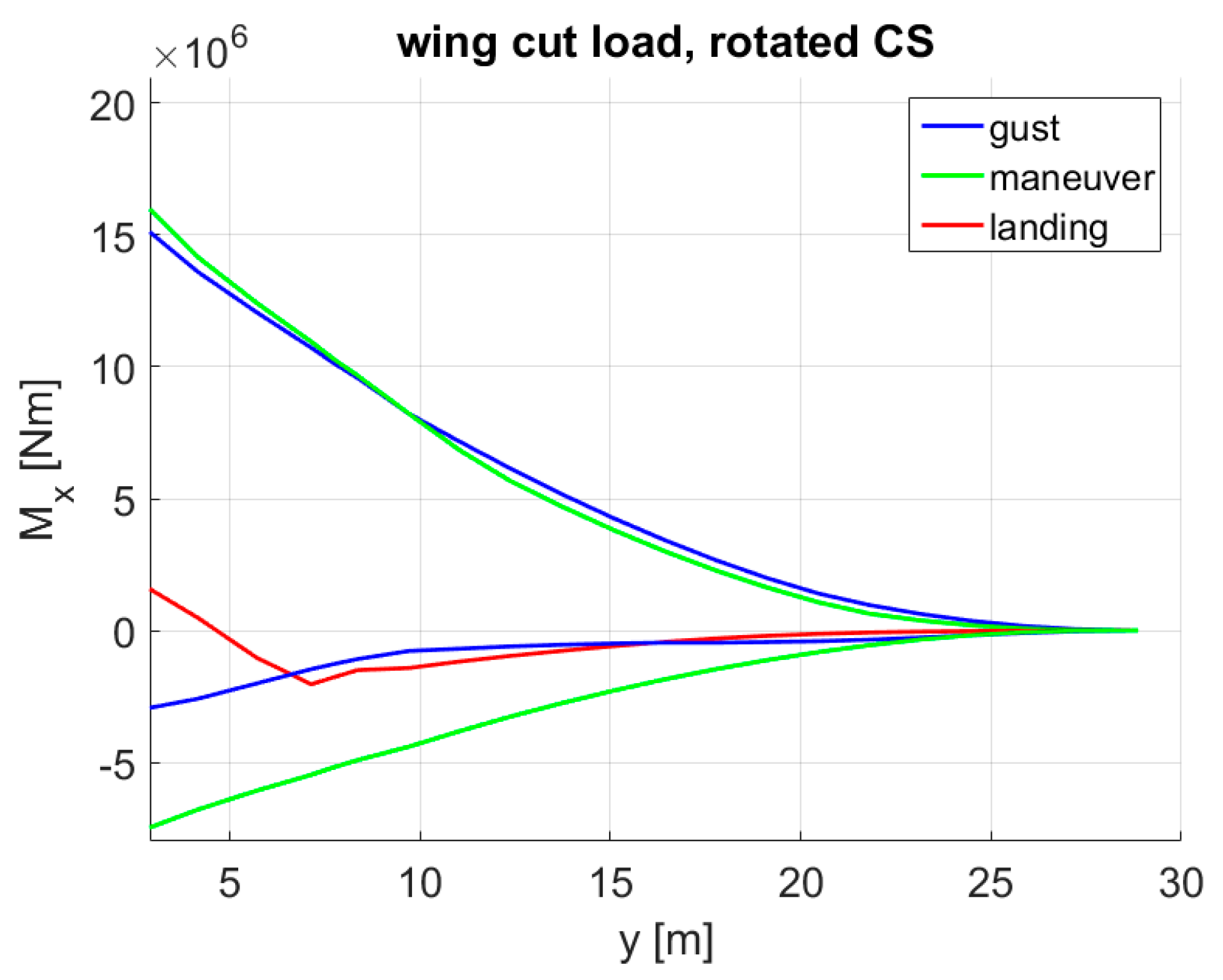
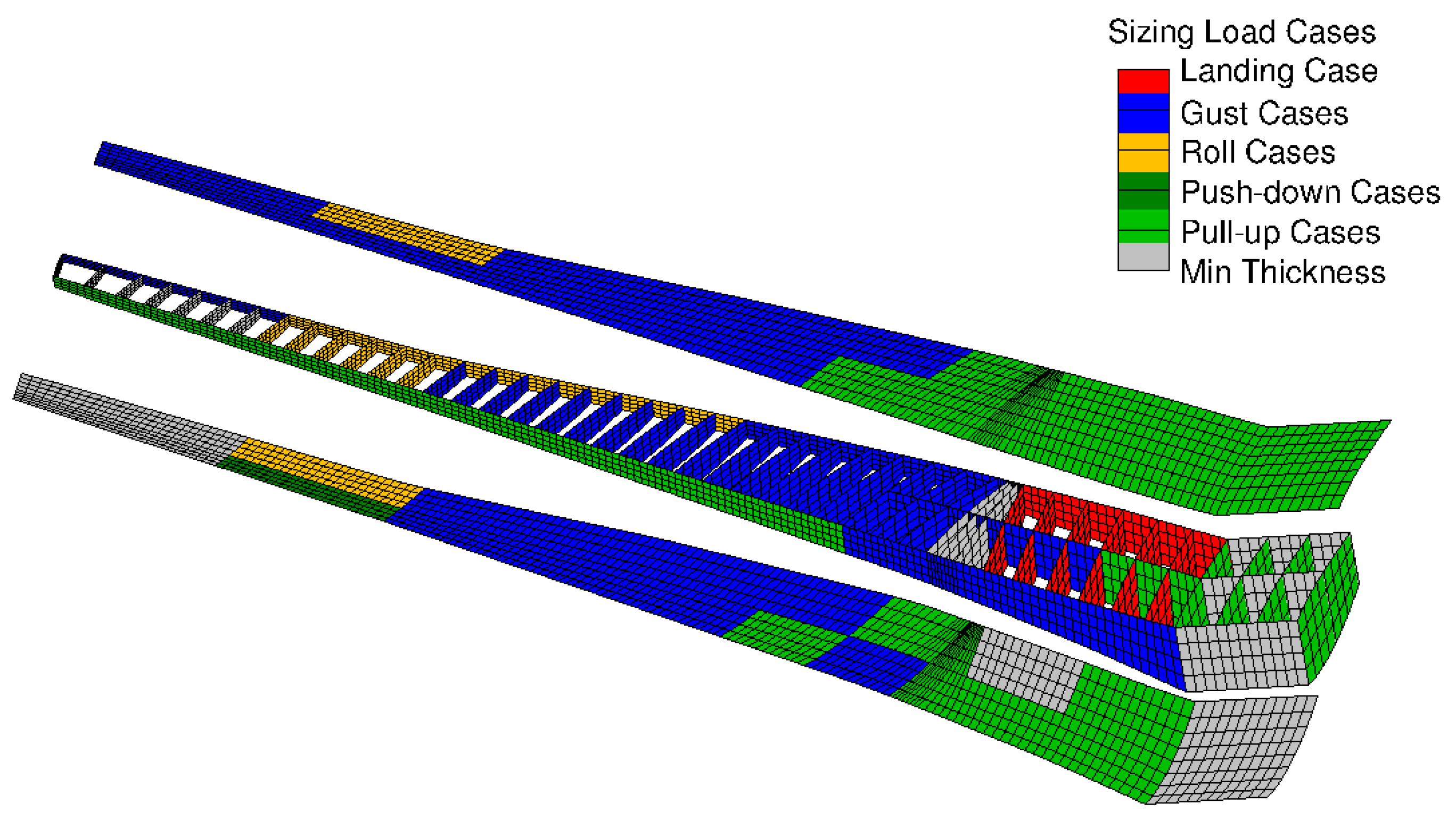
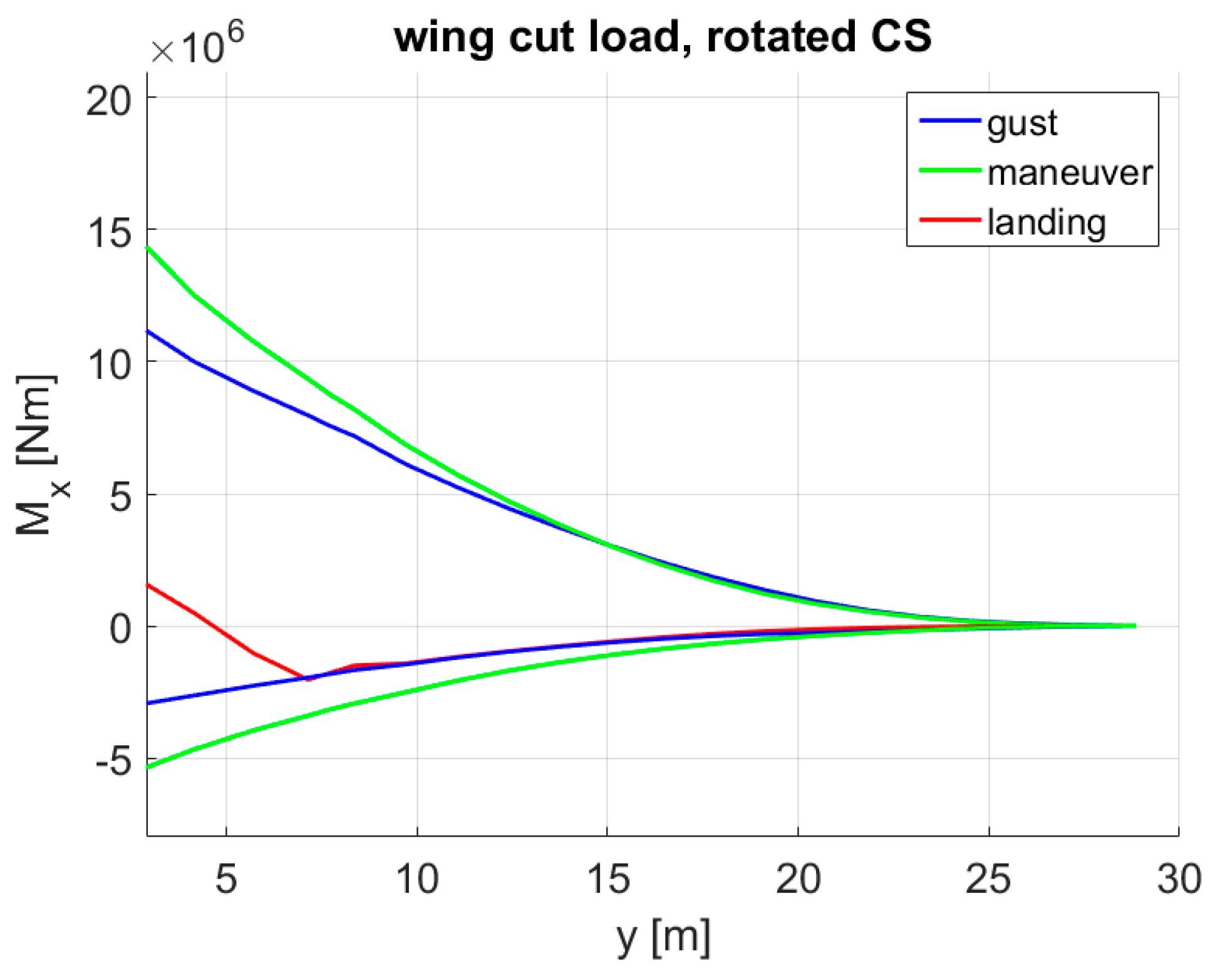
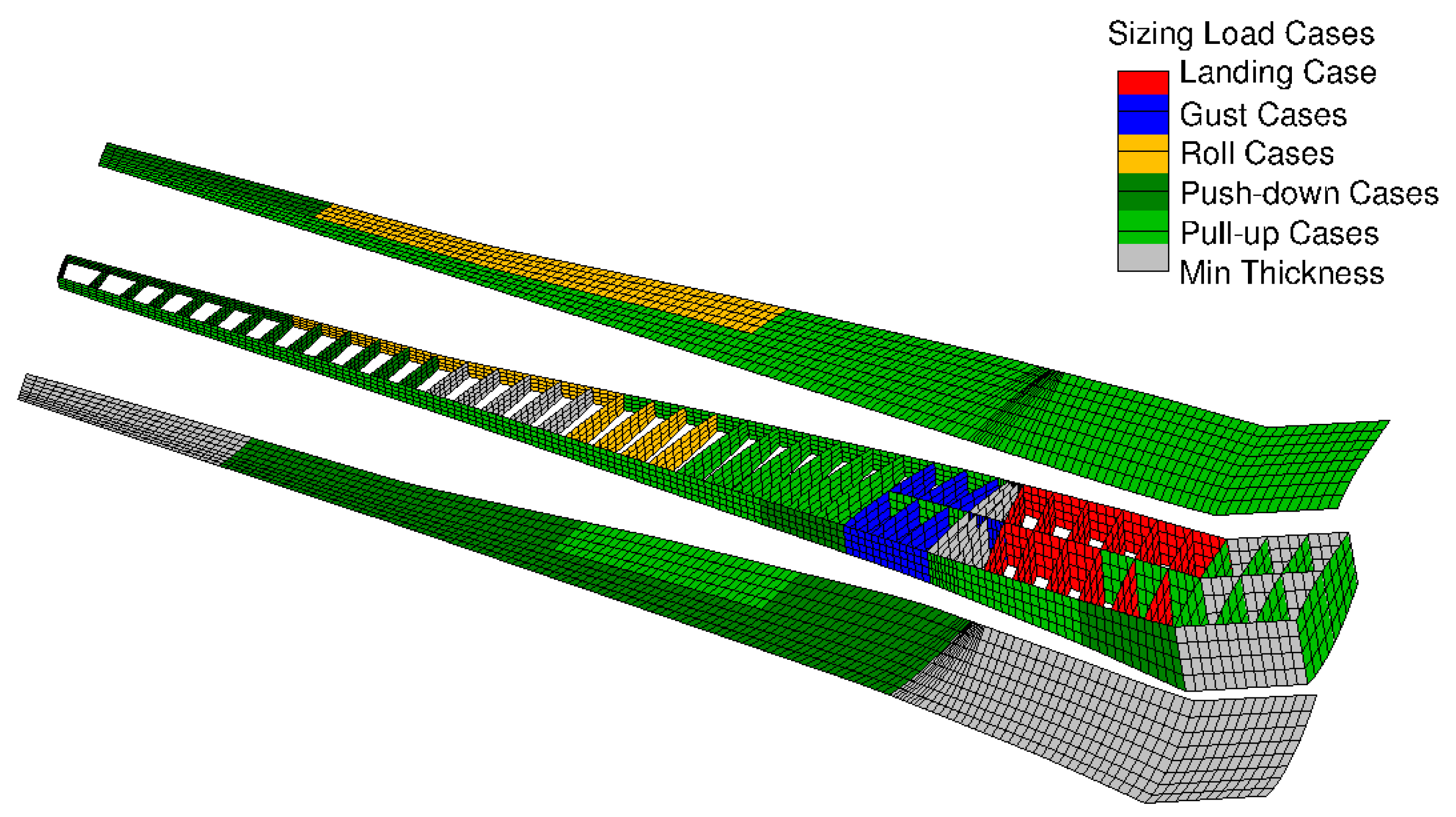
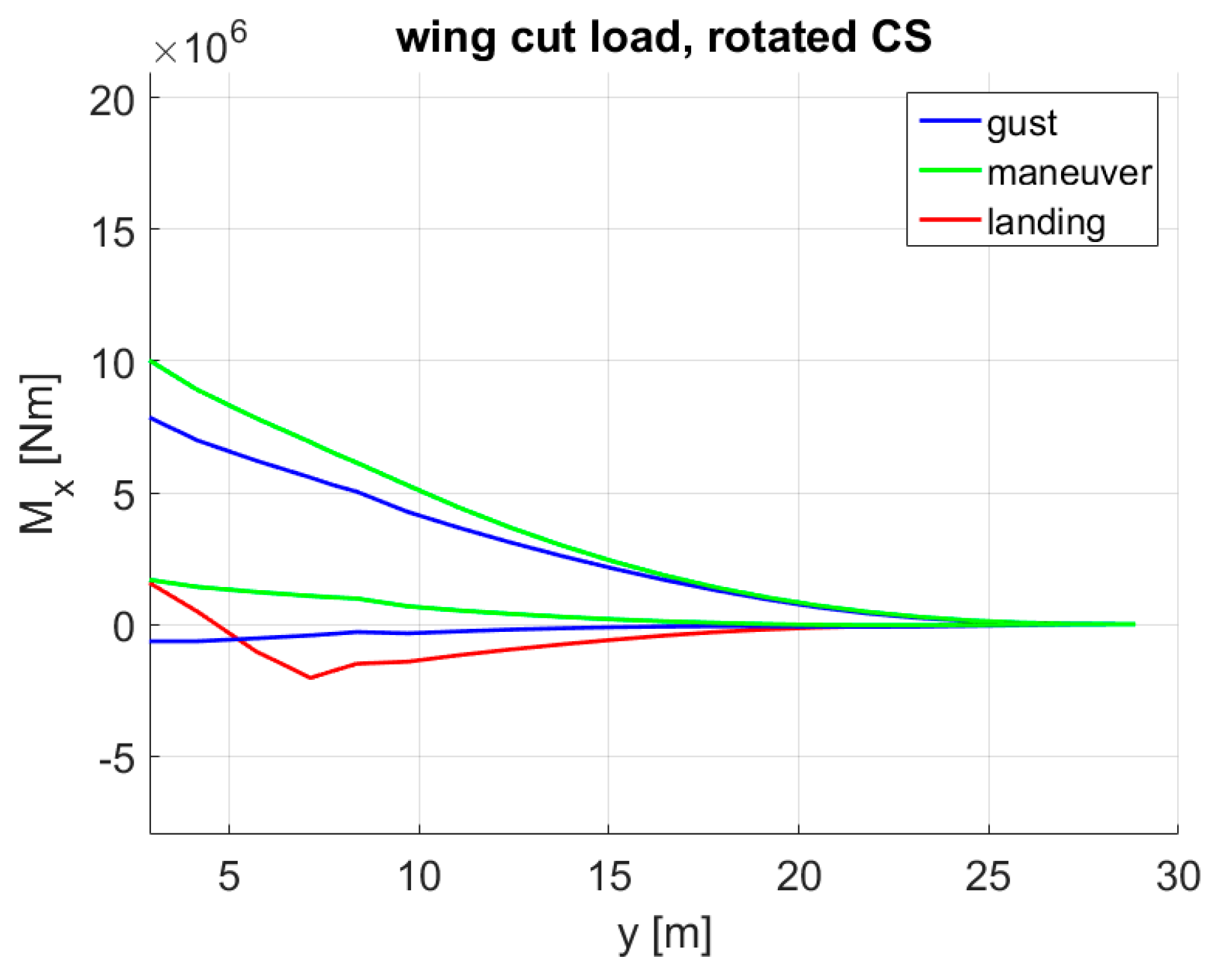
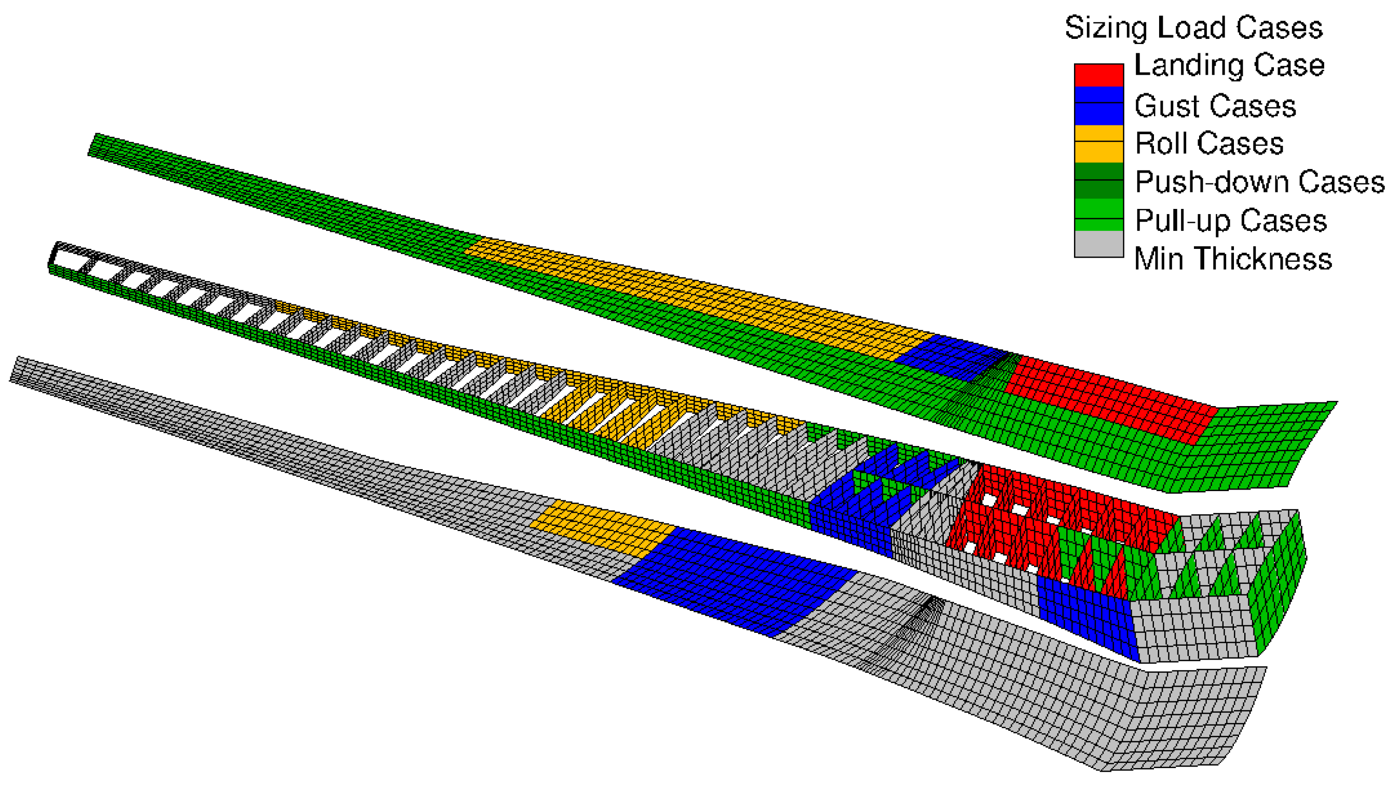
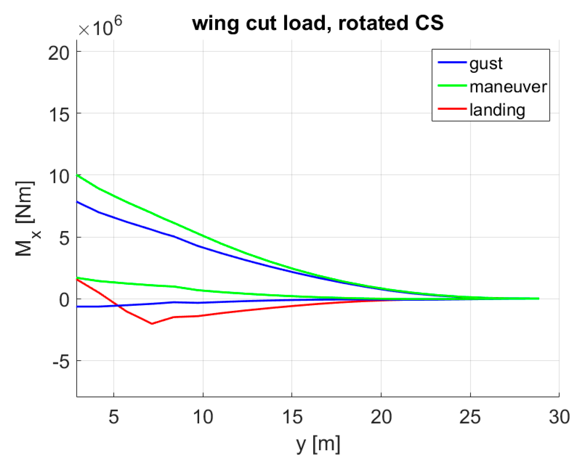
With the reference MLA algorithm, the largest wing bending moments along the entire wingspan were reached during gust encounters as shown in Figure 19. The bending moments were calculated in the local coordinate system of the wing shown in Figure 8. Coherent to the bending moments, the wing box was predominantly sized by the gust loads as apparent in Figure 20.
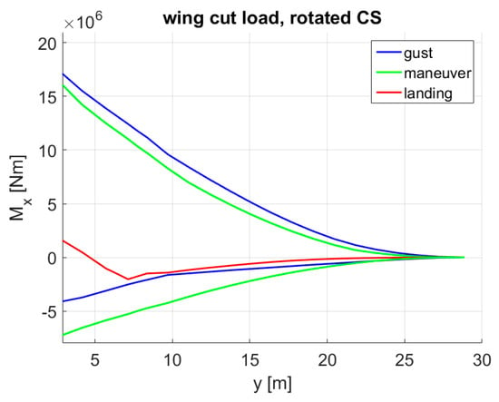
Figure 19.
Bending moment envelope of the reference aircraft.
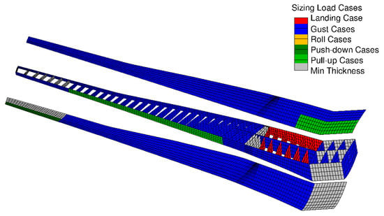
Figure 20.
Sizing load cases for each design field—reference.
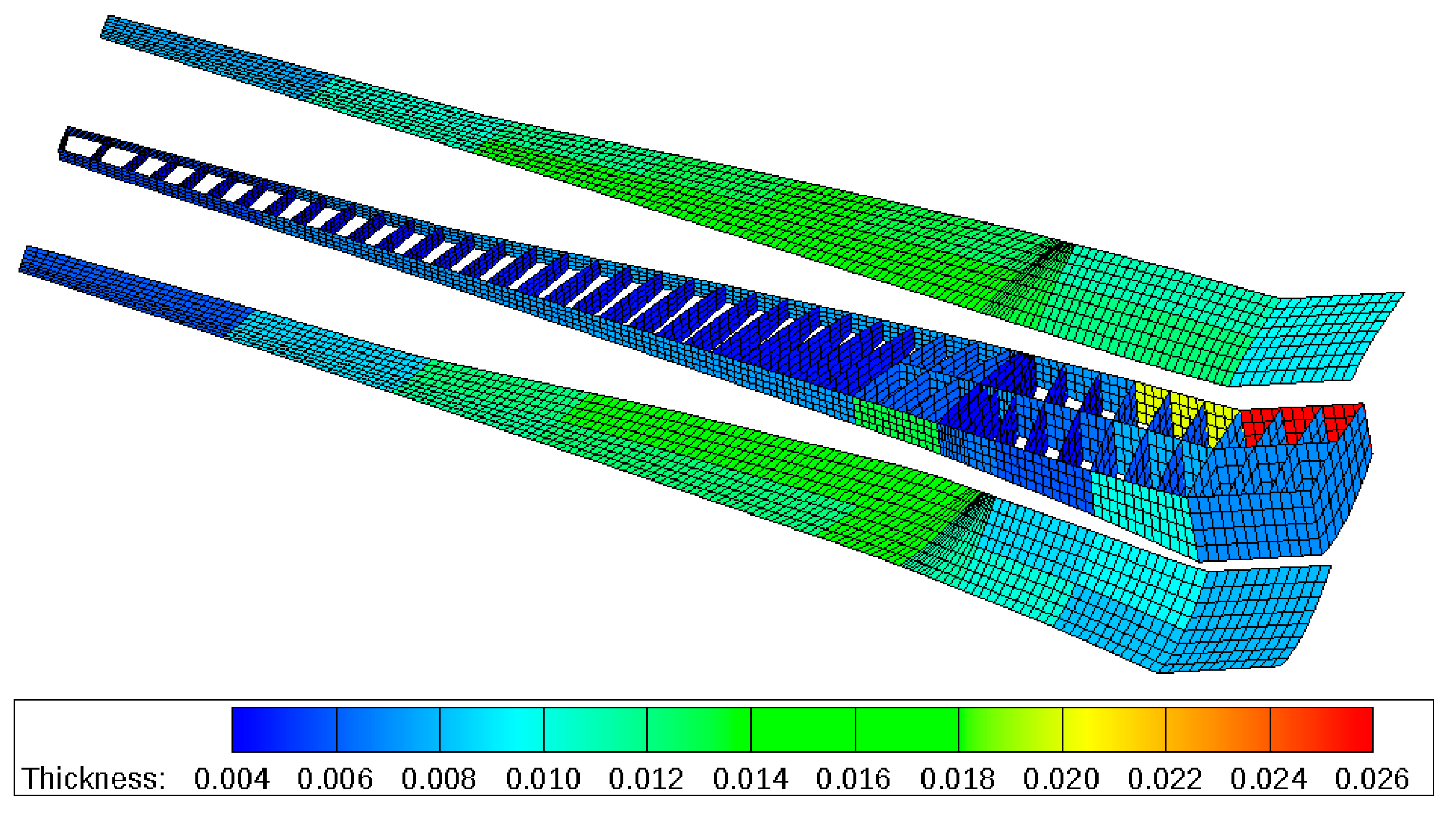
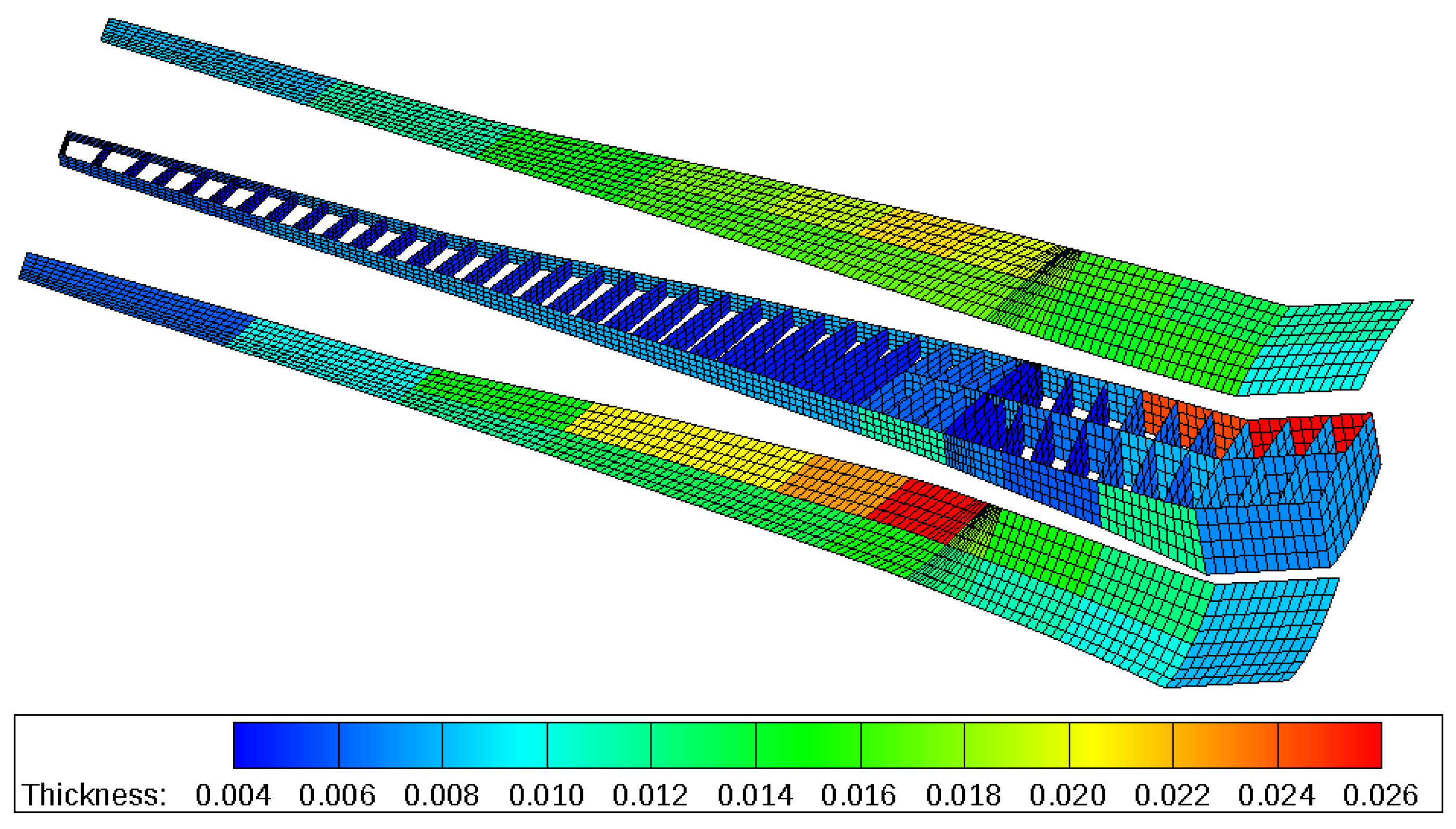
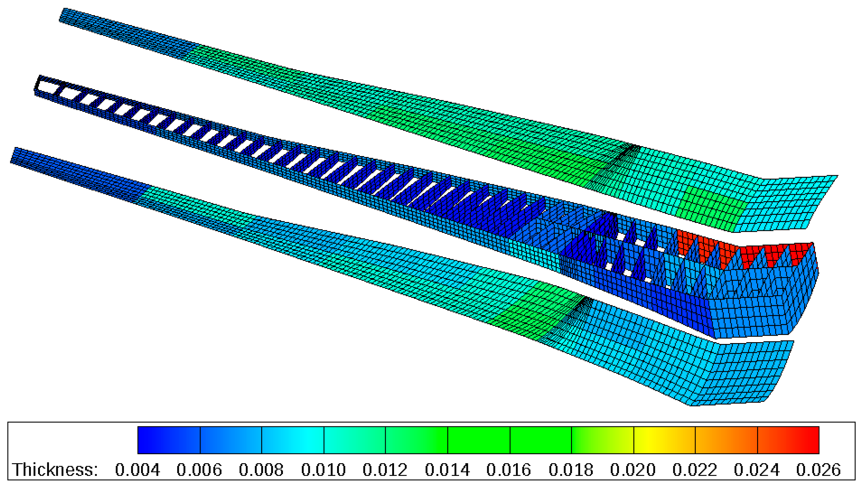
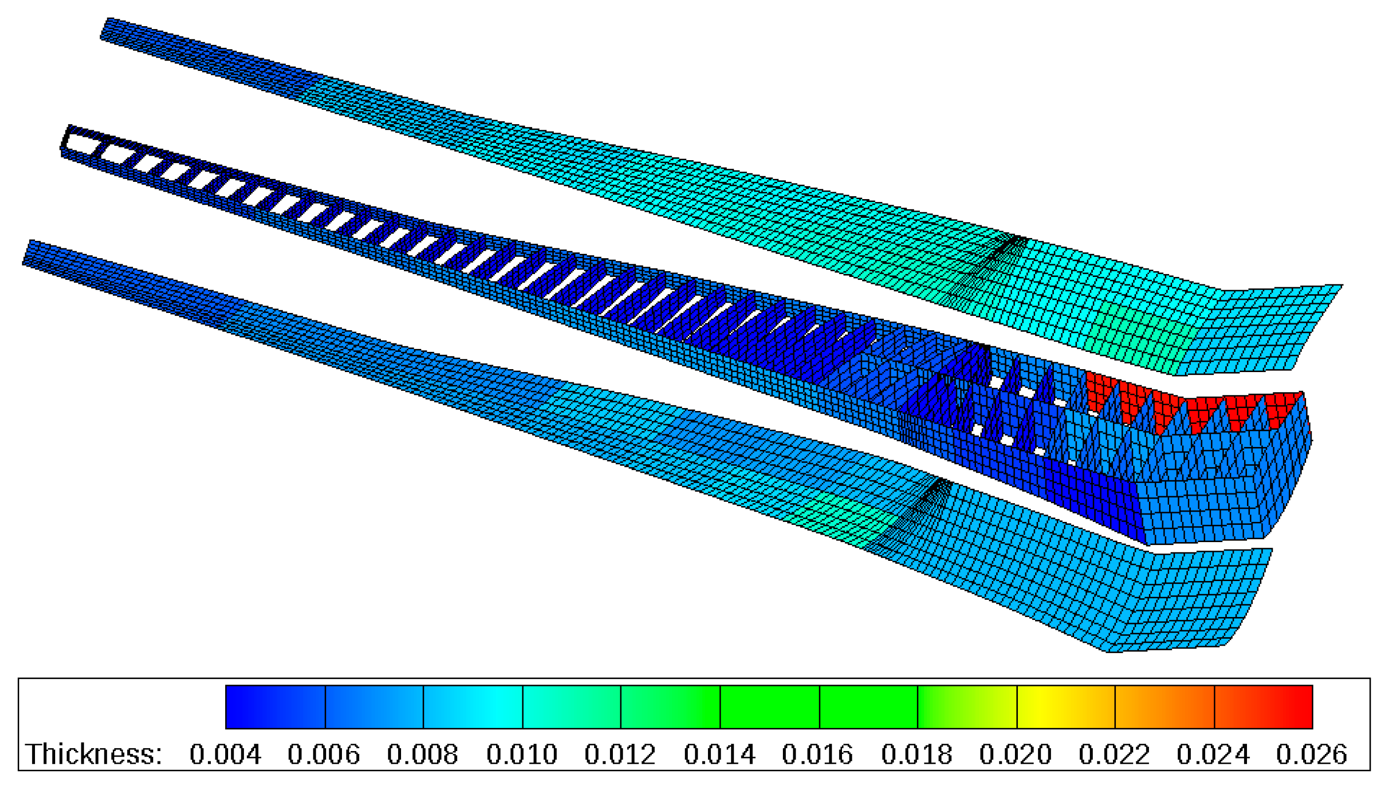
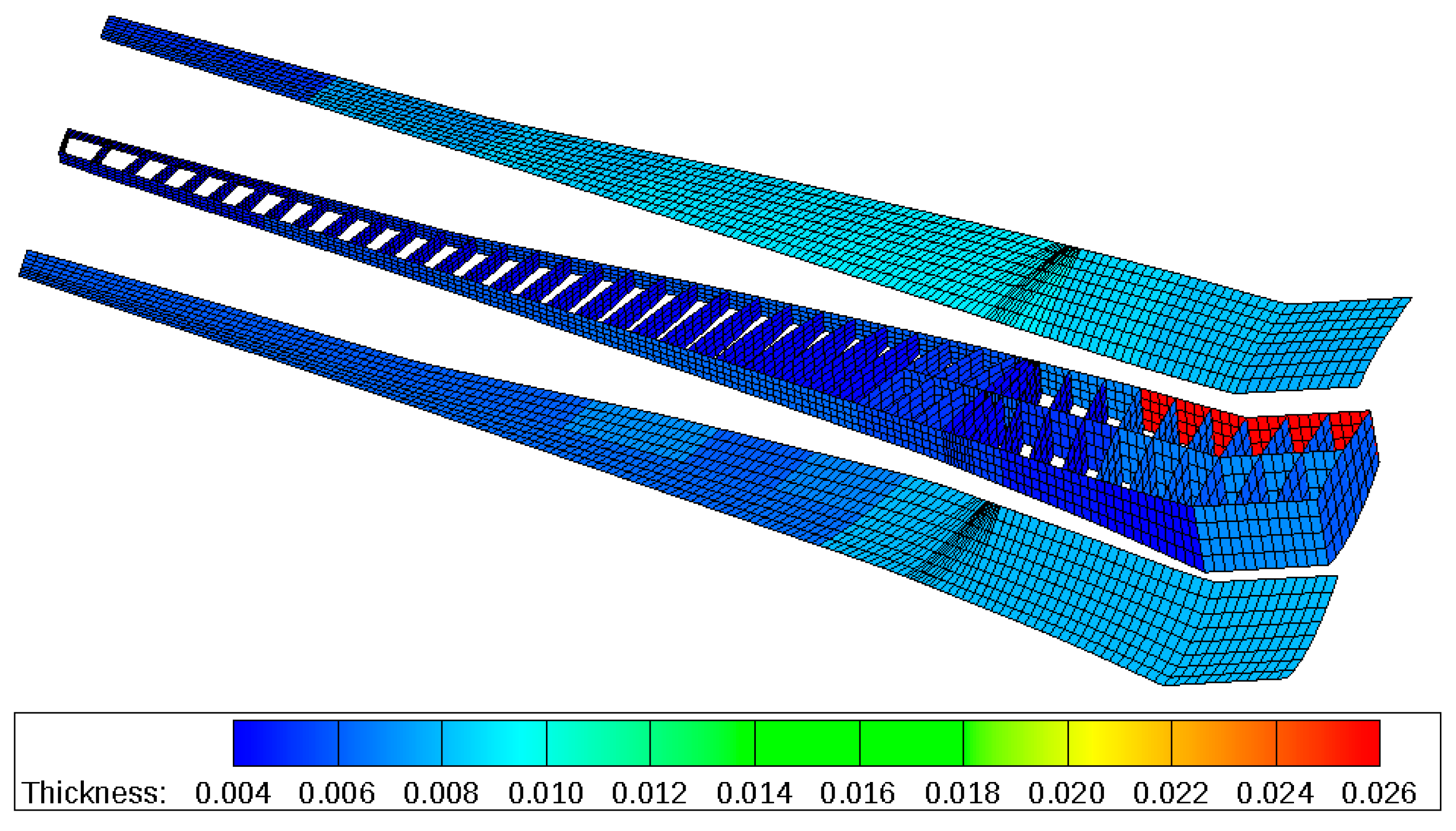
The total structural mass (tip to tip) of the wing box was 13,803 kg and the target wing mass—as explained in Section 2.2—according to the cpacs-file, was 34,300 kg (without the engines). Furthermore, Figure 21 shows the thickness distribution of the wing box. The maximum thickness of approx. 15 mm was found in the mid part of the wing.
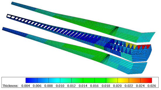
Figure 21.
Material thickness distribution in m—reference.
5.3. Passive Variant
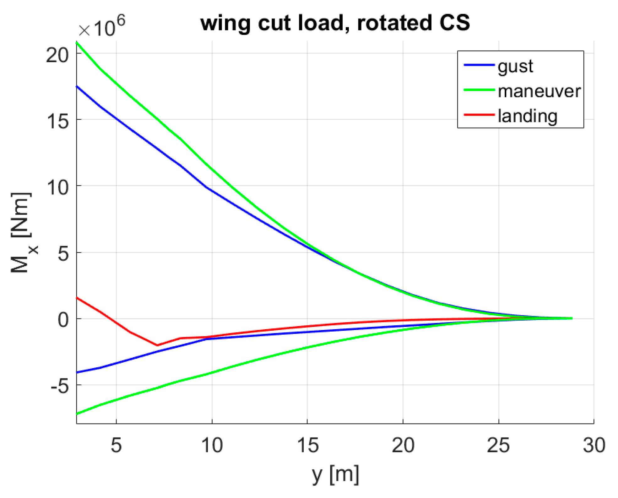
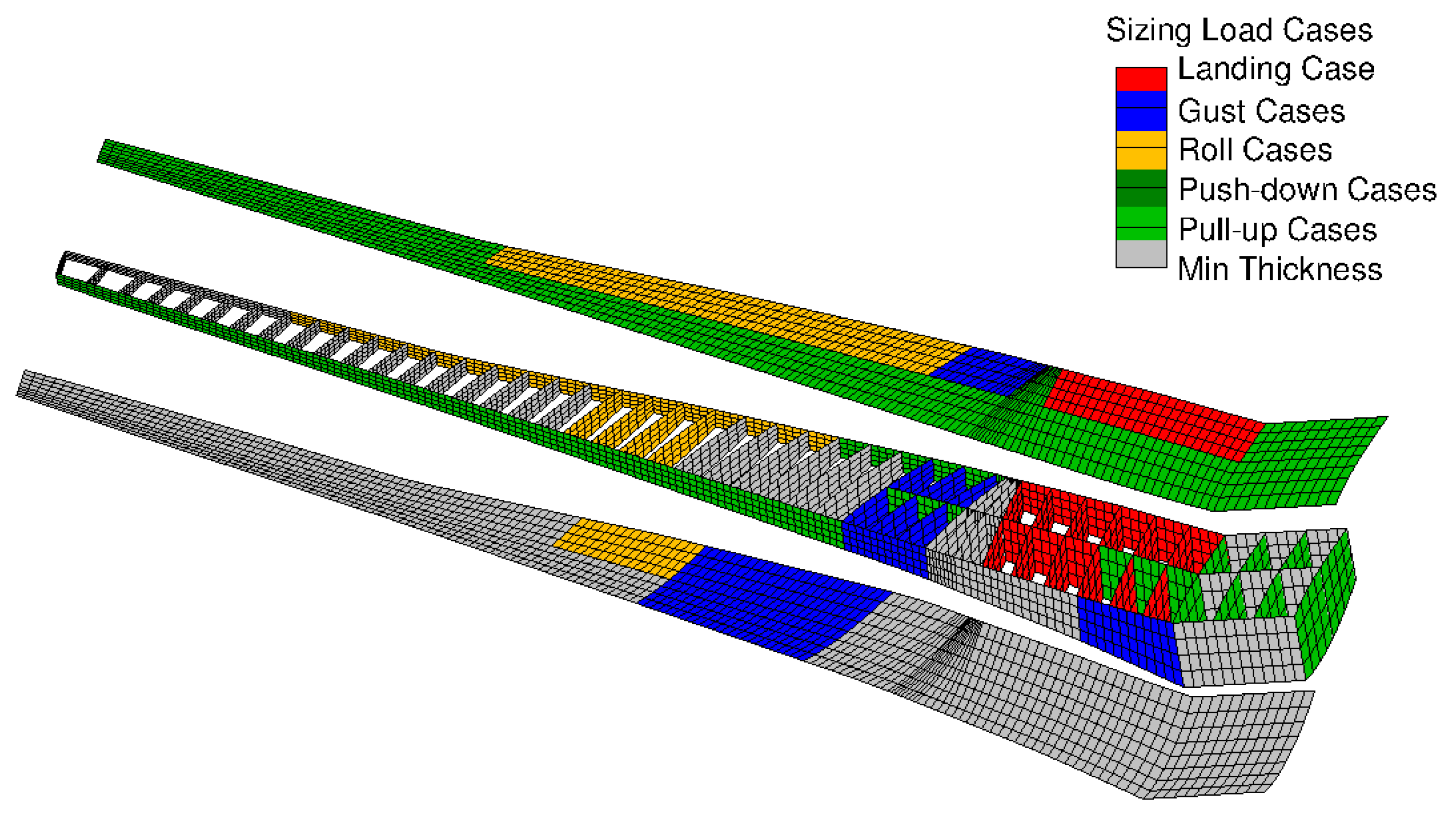
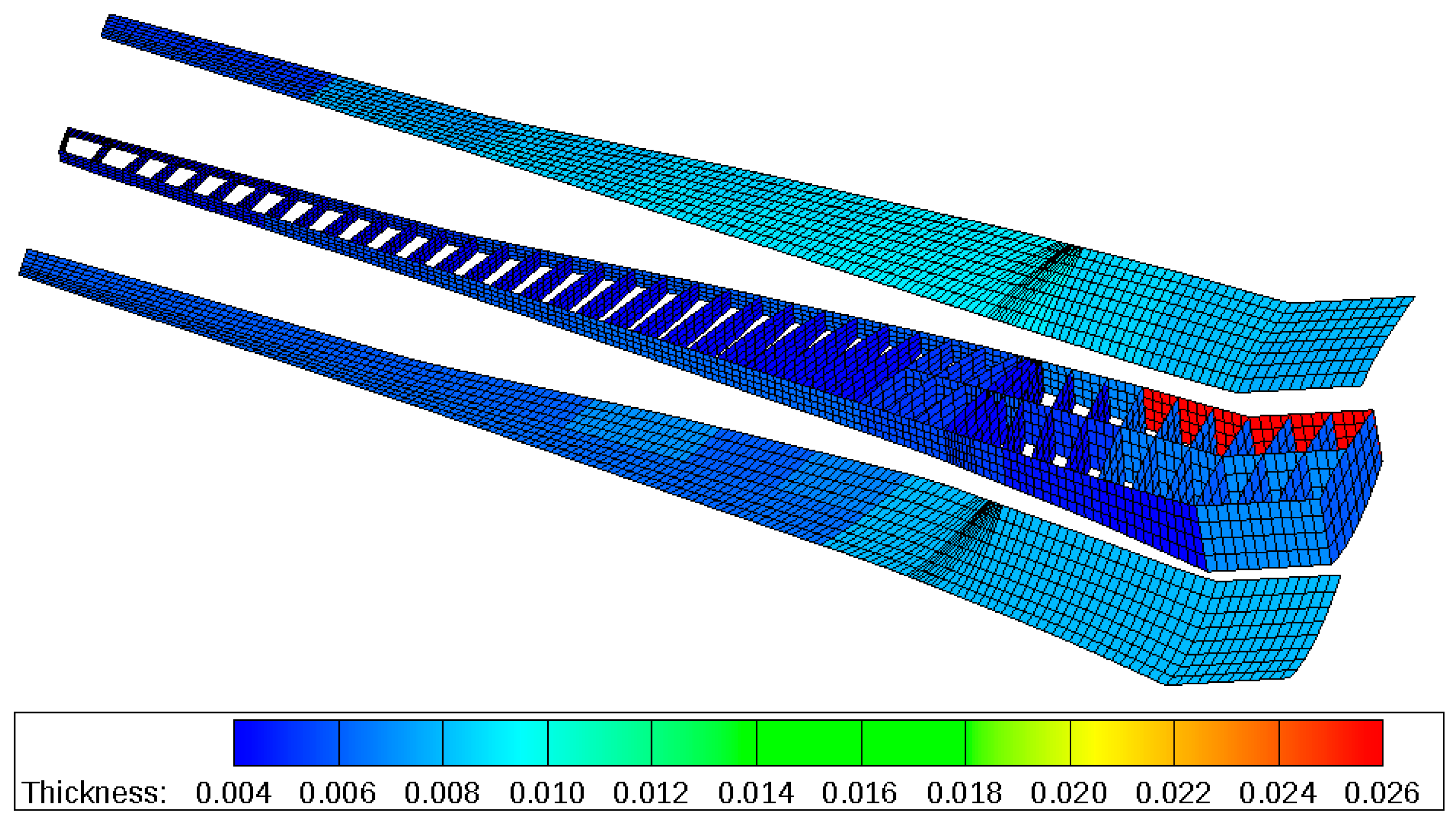
On the passive aircraft, the maximum bending moments due to maneuvers were dominant, especially in the inner part of the wing, as visible in Figure 22. As a consequence, the inner part of the wing box was predominantly sized by the maneuver loads, see Figure 23. The higher maximum bending moments were also visible in the higher material thicknesses. At the mid part of the wing, the material thickness reached values up to 26 mm on the lower skin and 21 mm on the upper skin as shown in Figure 24. On the passive variant, the total structural mass (tip to tip) of the wing box was 15,323 kg.
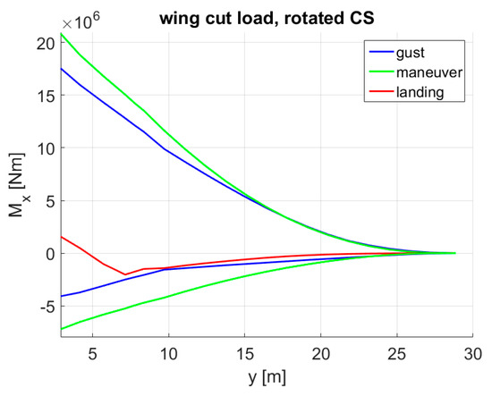
Figure 22.
Bending moment envelope of the passive variant.
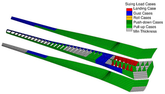
Figure 23.
Sizing load cases for each design field—passive variant.
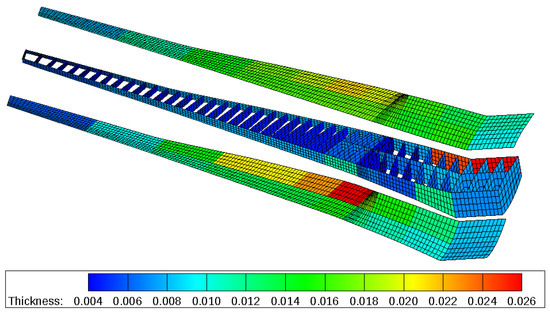
Figure 24.
Material thickness distribution in m—passive variant.
5.4. MLA + GLA
Compared to the reference, this variant had an additional gust load alleviation (GLA) besides the MLA. The implemented GLA algorithm is described in Section 4, and in this case, the deflected control surfaces were the ailerons as shown in Figure 25, with the GLA gain set to −2.5. This means, if the gust angle of attack was 1°, the ailerons were deflected trailing edge up (symmetrically) by 2.5° if all other control elements, such as the high pass and low pass filters, were switched off. According to the potential theory [24], with a control surface relative chord of 0.25 and an aerodynamic effectiveness of 0.75, a gain of −2.0 would already be sufficient to compensate for the lift increment due to a change in the angle of attack in a 2D case; however, since the ailerons have finite spans and a decrease in their effectiveness due to unsteady aerodynamics is expected, a raise in the gain magnitude to −2.5 was considered plausible.
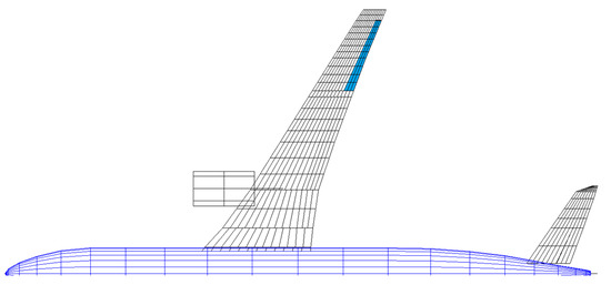
Figure 25.
Deflected control surfaces using the simple GLA algorithm.
With the additional GLA, the maximum bending moments due to gusts and maneuvers were approx. at similar levels along the entire wingspan, see Figure 26. Nevertheless, the gust loads were slightly higher at the outer wing part, whereas the maneuver loads were more dominant near the wing root. This aspect was also reflected by the sizing load cases of the wing box, for example, the outer part was predominantly sized by gusts, whereas the maneuver cases were found as the sizing ones beside the landing case around the root, see Figure 27. In the material thickness, the upper and lower skin at the mid part of the wing had an average thickness of 11 mm as shown in Figure 28. The total structural mass (tip to tip) of the wing box was 12,993 kg.
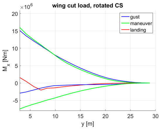
Figure 26.
Bending moment envelope with MLA + GLA.
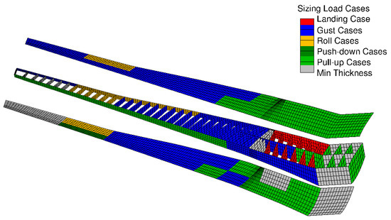
Figure 27.
Sizing load cases for each design field—MLA + GLA.
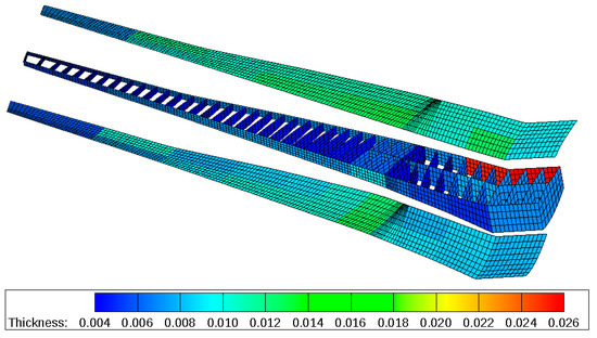
Figure 28.
Material thickness distribution in m—MLA + GLA.
5.5. MLA + GLA + Enhanced CS Layout (Enh. MLA + GLA)
For the enhanced control surface layout, the following changes were made:
- At the wing span positions where the high lift flaps were mounted, trailing edge control surfaces were assumed instead. This assumption was based on the multifunctional wing movable concept as elaborated by Reckzeh [28].
- MLA algorithm and control surface assignation. Instead of setting a fixed control surface deflection for every 2.5 g pull-up maneuver, the deflection was then a function of the equivalent airspeed:
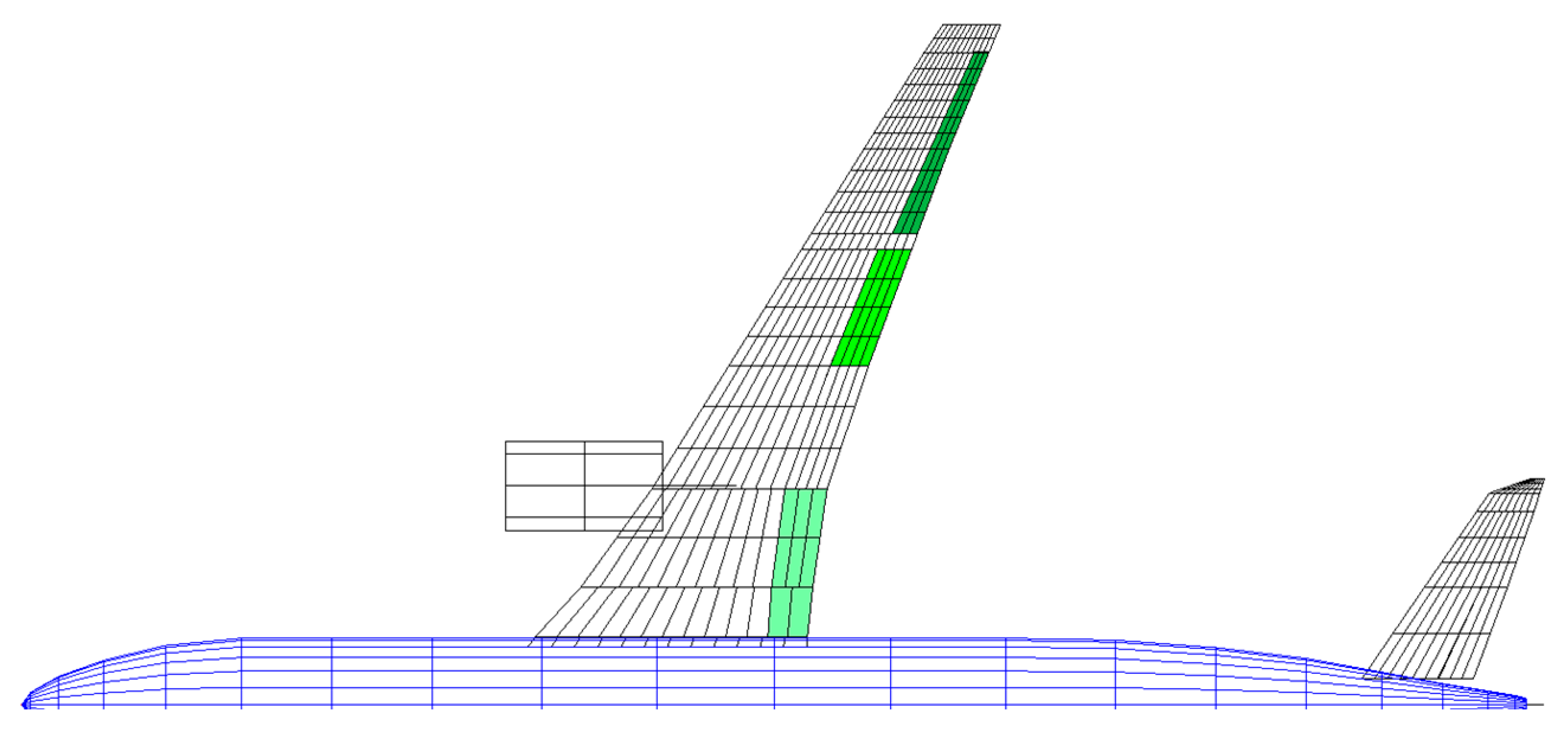
Figure 29 highlights the control surfaces which were deflected using the enhanced MLA algorithm.
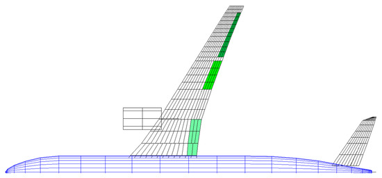
Figure 29.
Deflected control surfaces using the enhanced MLA algorithm.
For the 2.5 g pull-up maneuvers at , the deflection was set to:
- ○
- −20° (trailing edge up) for the ailerons,
- ○
- −10° (trailing edge up) for the outer half of the outer flaps (bright green area in Figure 29),
- ○
- +10° (trailing edge down) for the inner flaps (light green are near the root).
For the −1 g push-down maneuvers at , the deflection was set to:
- ○
- +20° (trailing edge down) for the ailerons,
- ○
- +10° (trailing edge down) for the outer half of the outer flaps,
- ○
- −10° (trailing edge up) for the inner flap.
In general, the inner flap deflection increased the lift at the root, while the deflection of the outer flap and ailerons decreased the lift at the outer wing part.
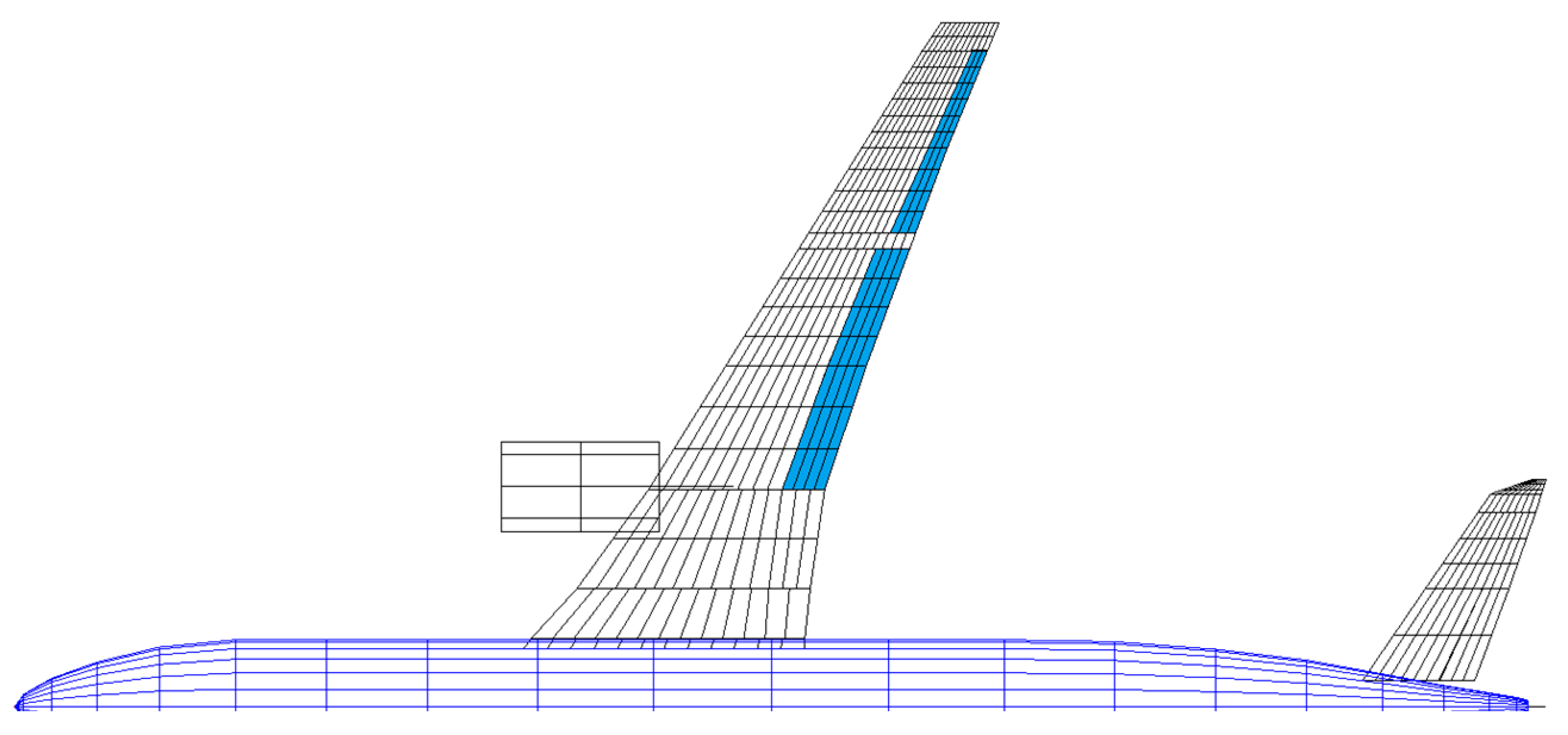
- GLA gain and control surface assignment. The implemented GLA was designed to reduce the incremental gust loads. In doing so, the more control surfaces that were deflected by GLA, the higher were the achievable gust load reductions; hence, the outer flaps were also deflected beside the ailerons in the enhanced GLA algorithm, see Figure 30.Theoretically, the inner flaps could be deflected as well; however, those are seen to be ineffective in reducing the wing root bending moment since the lever is relatively short. Moreover, due to the large wing chord around the root, an inner flap deflection is expected to evoke large torsion moments which are undesirable. With the aileron and outer flap deflection, the GLA gain was reduced to −2.0 to avoid having an excessive increase in the torsion moments due to the larger total area of the deflected control surfaces. Furthermore, gust cases with airbrakes were not considered, since the airbrakes with the enhanced layout were assumed not to change the lift distribution.
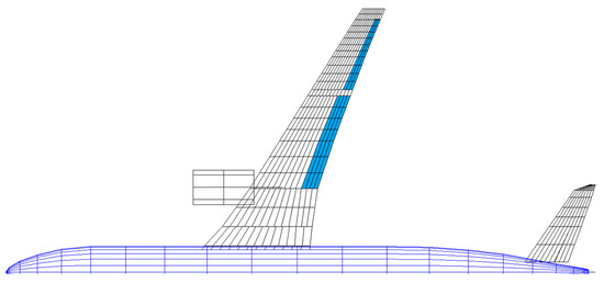
Figure 30.
Deflected control surfaces using the enhanced GLA algorithm.
Figure 30.
Deflected control surfaces using the enhanced GLA algorithm.
With the enhanced MLA and GLA, the maximum wing root bending moment was reduced by 15.4% compared to the reference variant, see Figure 31. Furthermore, the maneuver loads were dominant, especially around the wing root. This aspect was also found in the sizing load cases of the wing box, for example, the wing box was predominantly sized by maneuvers, see Figure 32. Moreover, the lower skin around the wing root was so thin that it had already reached its minimum thickness of 8 mm. At the mid part of the wing, the upper skin thickness was 10 mm in average, whereas the lower skin thickness was approx. 8 mm as shown in Figure 33. The total structural mass (tip to tip) of the wing box was 12,184 kg.
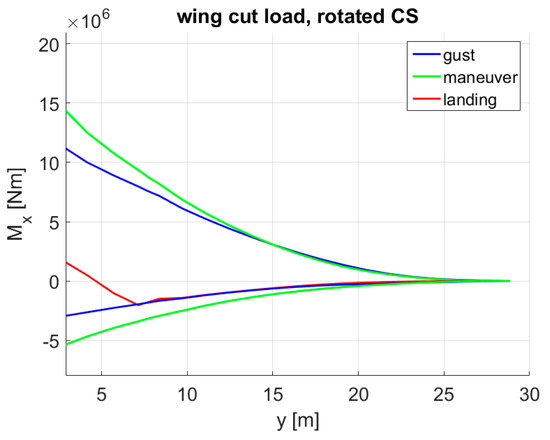
Figure 31.
Bending moment envelope with enhanced MLA + GLA.
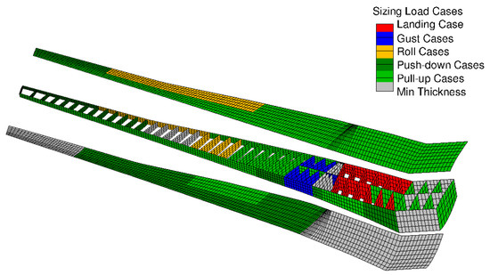
Figure 32.
Sizing load cases for each design field—enhanced MLA + GLA.
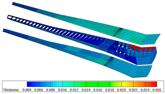
Figure 33.
Material thickness distribution in m—enhanced MLA + GLA.
5.6. MLA + GLA + Enhanced CS Layout + Reduced Design Load Factor (Red. Load Factor)
For this variant, hypothetical scenarios, future technologies and infrastructures were assumed, and the following changes were made:
- The range of the design load factor was reduced to +0.5 g – +1.5 g. This assumption was based on the statistical loads data of a Boeing 777-200ER provided by the FAA [25]. According to the data extracted from 10,047 flights, accelerations below +0.5 g and above +1.5 g were exceeded in less than 1% of the samples, see Figure 34. Furthermore, it has to be remarked that the highest accelerations were more likely to be reached with lighter mass configurations where the wing loads were relatively low. Hence, a design load factor up to 1.5 g at masses up to MTOM is seen as more conservative.
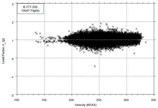 Figure 34. Acceleration data of a Boeing 777-200ER [25].
 - For the 1.5 g pull-up maneuvers at , the MLA deflection was set to:
- ○
- −10° (trailing edge up) for the ailerons,
- ○
- −5° (trailing edge up) for the outer half of the outer flaps (bright green area in Figure 29),
- ○
- +5° (trailing edge down) for the inner flaps (light green are near the root).
The chosen MLA amplitudes were lower compared to those with the design load factor of 2.5 to avoid changing the lift distribution—thus potentially the stall speed—too aggressively since load factors up to 1.5 are reached significantly more often in the operation. For the 0.5 g push-down maneuvers, the MLA was not active since the load amplitudes were smaller compared to the 1 g static loads.
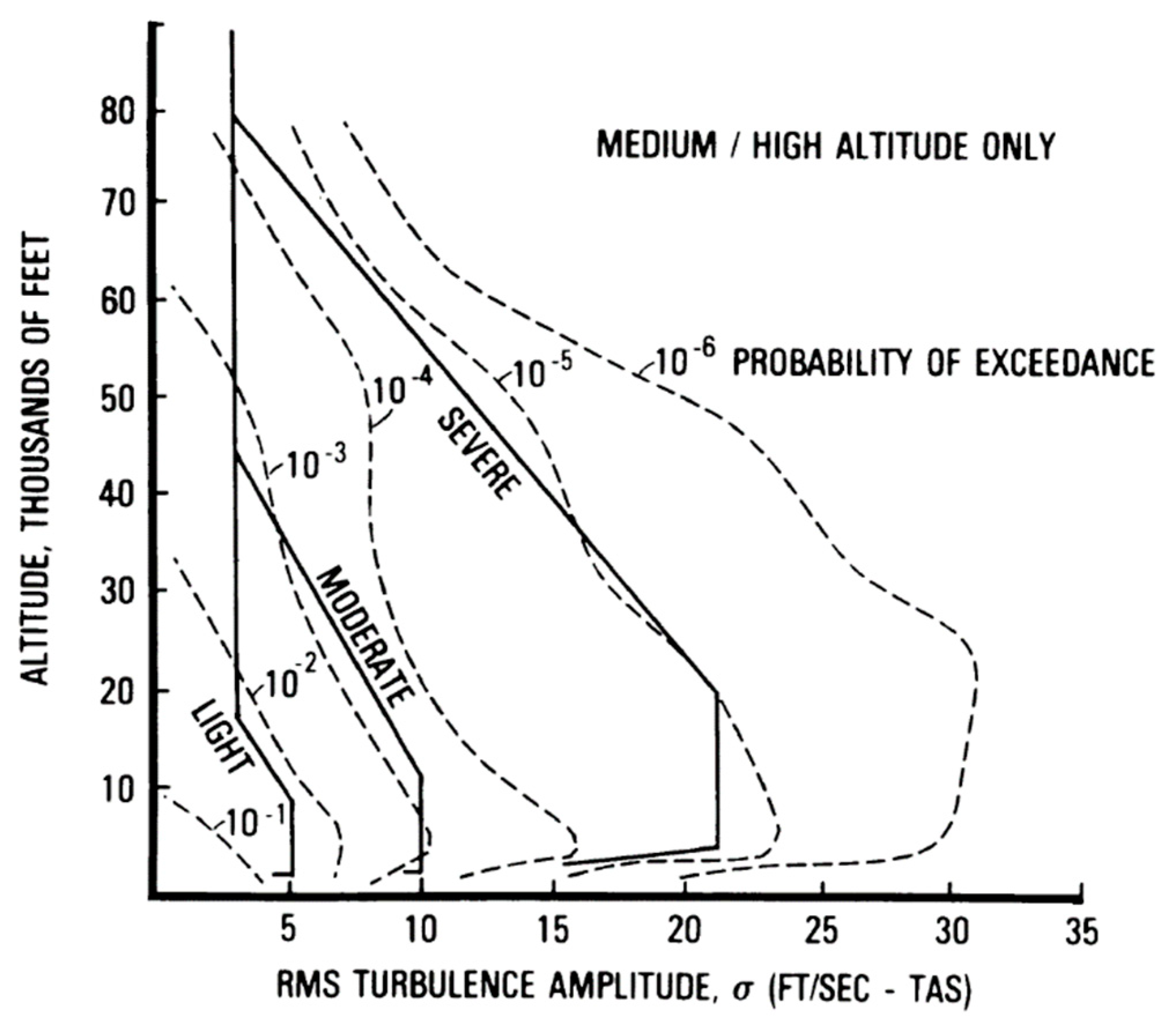
- The design gust speeds prescribed in CS25 [27] were reduced to half of the initial values. This is based on the data on turbulence intensities according to MIL-STD-1797A [29] as shown in Figure 35. At this point, the gust speeds given in CS25 were assumed to be equivalent to a probability of 1 × 10⁻⁵/h. If future technologies can predict turbulences and gusts with a higher reliability, the design gust speeds can be reduced so that they are equivalent to a probability of exceedance of 1 × 10⁻³/h. In Figure 35, if the altitude of 10,000 ft is taken as a reference, the turbulence intensity with a probability of 1 × 10⁻³/h is approx. half of that with a 1 × 10⁻⁵/h probability. In this case, the GLA gain was kept constant. With the lower gust speeds, the control surface deflection was accordingly smaller.
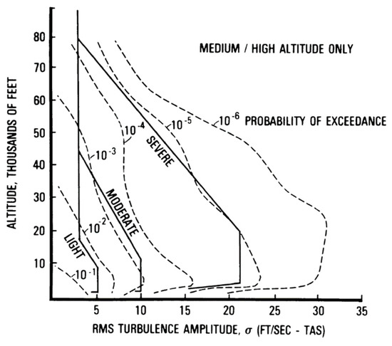
Figure 35.
Probability distribution of turbulence intensities [29].
Figure 35.
Probability distribution of turbulence intensities [29].
With a maximum design load factor of +1.5, the maximum wing root bending moment was reduced by 43.8% compared to the reference variant, as apparent in Figure 36. Over the entire wingspan, the maneuver loads evoked the highest bending moments. Figure 37 shows that the upper skin was predominantly sized by the maneuver loads, with patches that were sized by the gust loads. Furthermore, large areas of the lower skin were at a minimum thickness, whereas the upper skin at the mid wing part had an average thickness of 9 mm, see Figure 38. The total structural mass (tip to tip) of the wing box was 10,322 kg.
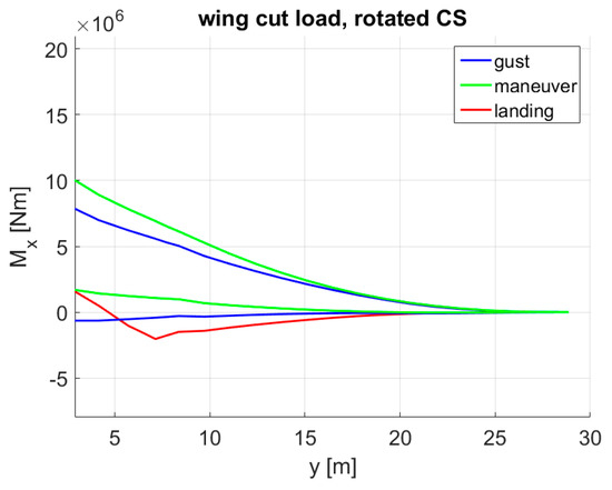
Figure 36.
Bending moment envelope with red. load factor.
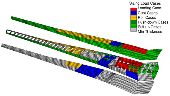
Figure 37.
Sizing load cases for each design field—red. load factor.
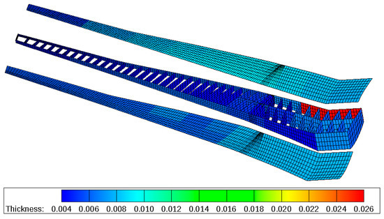
Figure 38.
Material thickness distribution in m—red. load factor.
5.7. MLA + GLA + Enhanced CS Layout + Reduced Design Load Factor + Reduced Safety Factor (Red. Safety Factor)
On this variant, the safety factor was reduced from 1.5 to 1.3. It was assumed that the safety factor prescribed in CS25 [27], among others, takes material degradation and fatigue throughout the service life into account, so that the aircraft can still withstand a limit loading at the end of its service life. On one hand, the fatigue behavior of composite materials is known to be superior compared to their aluminum counterpart. On the other hand, if, hypothetically, the material degradation during the service life can be reduced and all other constraints can be complied with, the safety factor can be reduced, e.g., to 1.3.
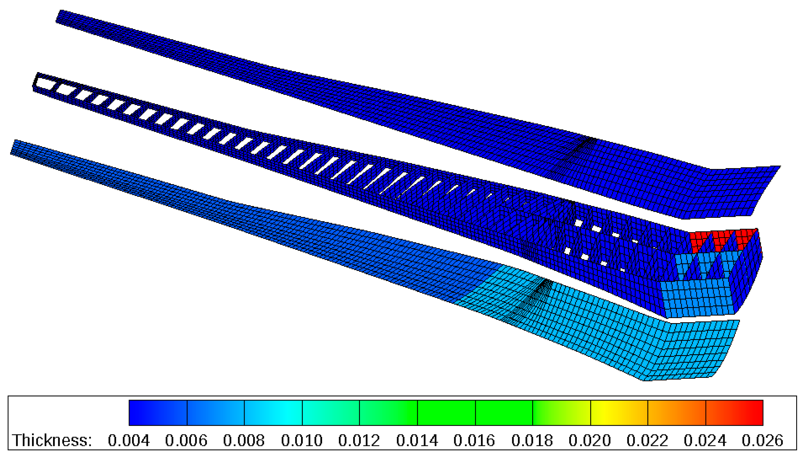
With a maximum design load factor of +1.5, the maximum wing root bending moment was reduced by about 44% compared to the reference variant, see Figure 39. Furthermore, a larger portion of the wing box was at the minimum thickness, while the upper skin was still predominantly sized by maneuvers (pull-up and roll) as apparent in Figure 40. In the material thickness, the most distinctive difference compared to red. load factor was found at the rear spar near the root, which was sized by the landing loads as shown in Figure 41. The total structural mass (tip to tip) of the wing box was 10,143 kg.
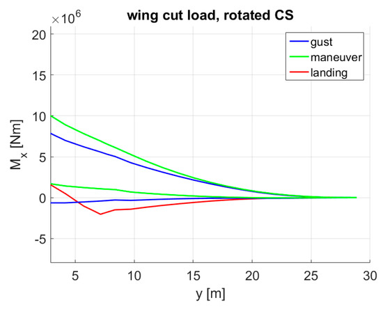
Figure 39.
Bending moment envelope with red. safety factor.
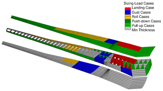
Figure 40.
Sizing load cases for each design field—red. safety factor.
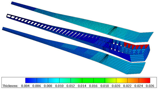
Figure 41.
Material thickness distribution in m—red. safety factor.
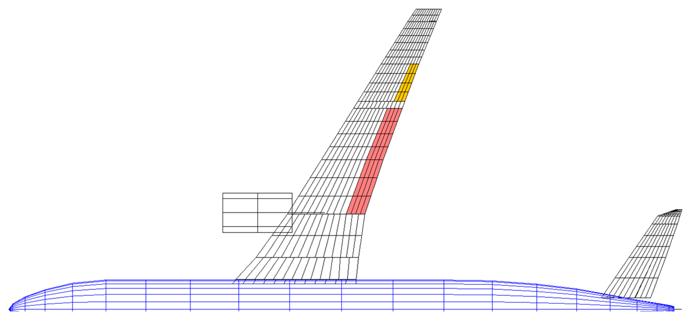
On this variant, the inner aileron effectiveness (yellow highlighted area in Figure 42) at the highest dynamic pressure (at ) was 34.6%, and this was the lowest expected value among all the described test cases due to its lowest wing stiffness. With the enhanced control surface layout, however, it was assumed that the control surfaces inboard of the ailerons (red area in Figure 42) were also used for roll maneuvers. Since inboard control surfaces are expected to have a higher effectiveness compared to ailerons in general, potential aileron reversal issues were not investigated.
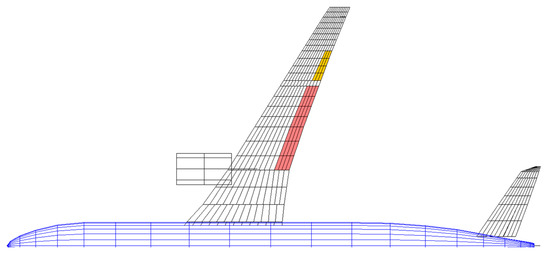
Figure 42.
Deflected control surfaces for roll maneuver with the enhanced control surface layout.
5.8. Minimum Thickness
The wing box with a minimum skin thicknesses was addressed to give an insight into the fraction size of the wing structural mass which was already limited by manufacturing and operational constraints. On the upper skin and the ribs, the minimum thickness was 4 mm. On the lower skin, the outer wing part had a minimum thickness of 6 mm and the inner part was 8 mm thick to withstand debris impact and tire bursts. Moreover, the rear spar of the center wing box was set to 26 mm to take the mass penalties due to the landing gear storage into account, whereas the front and middle spar thicknesses were set to 7 mm. The stiffener thicknesses were taken from a pre-sizing calculation with a load factor of 1 g. If the corresponding skin thicknesses were reduced to the minimum values, however, the wing could not withstand a 1 g loading. Figure 43 visualizes the minimum thickness distribution. The total structural mass (tip to tip) of the wing box was 7992 kg.
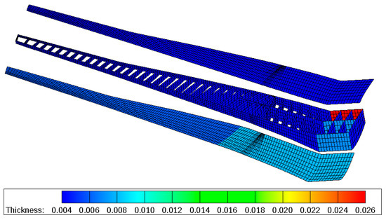
Figure 43.
Material thickness distribution in m—minimum thicknesses.
5.9. Summary of Load Results and Aeroelastic Parameters
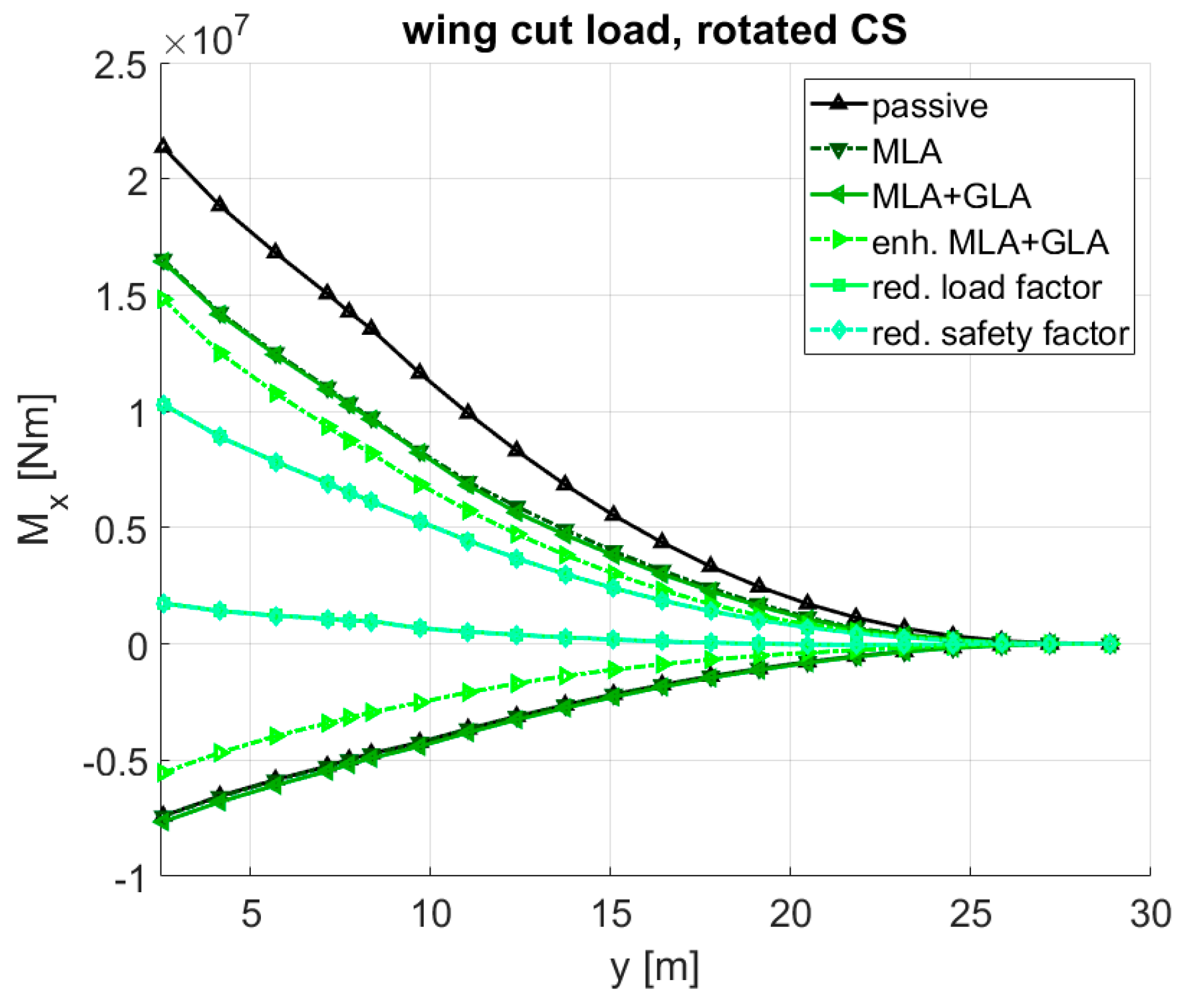
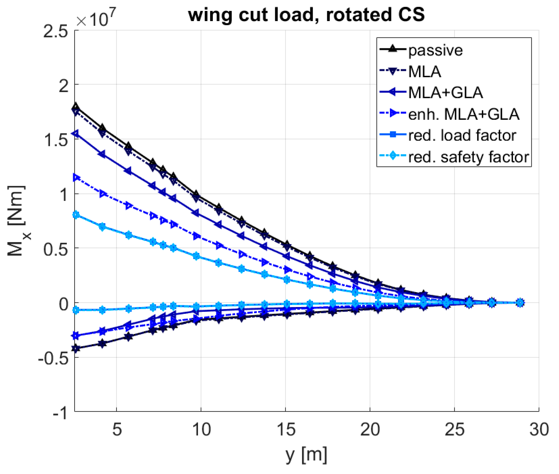
For a better overview of the bending moments, Figure 44 visualizes the maneuver load envelopes for all six test cases, and Figure 45 shows the gust load envelopes. Some of the curves lie almost on top of each other, e.g., those of the red. load factor and red. safety factor, because there was no change in the design load conditions nor in the load alleviation settings.
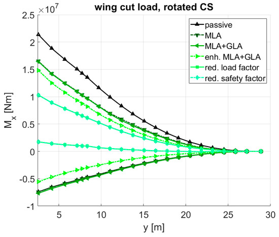
Figure 44.
Overview of maneuver bending moment envelopes.
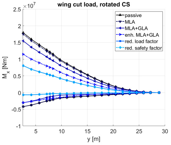
Figure 45.
Overview of gust bending moment envelopes.
In the maneuver bending moments, one large reduction was achieved with the introduction of MLA (the difference between passive and MLA). Another large reduction emerged with the introduction of the reduced design load factor (the difference between enh. MLA + GLA and the red. load factor). For the gust bending moments, a large load reduction was achieved with an enhanced GLA (the difference between MLA + GLA and an enh. MLA + GLA). Another large gust load reduction was reached through the reduced design gust speeds (the difference between enh. MLA + GLA and the red. load factor).
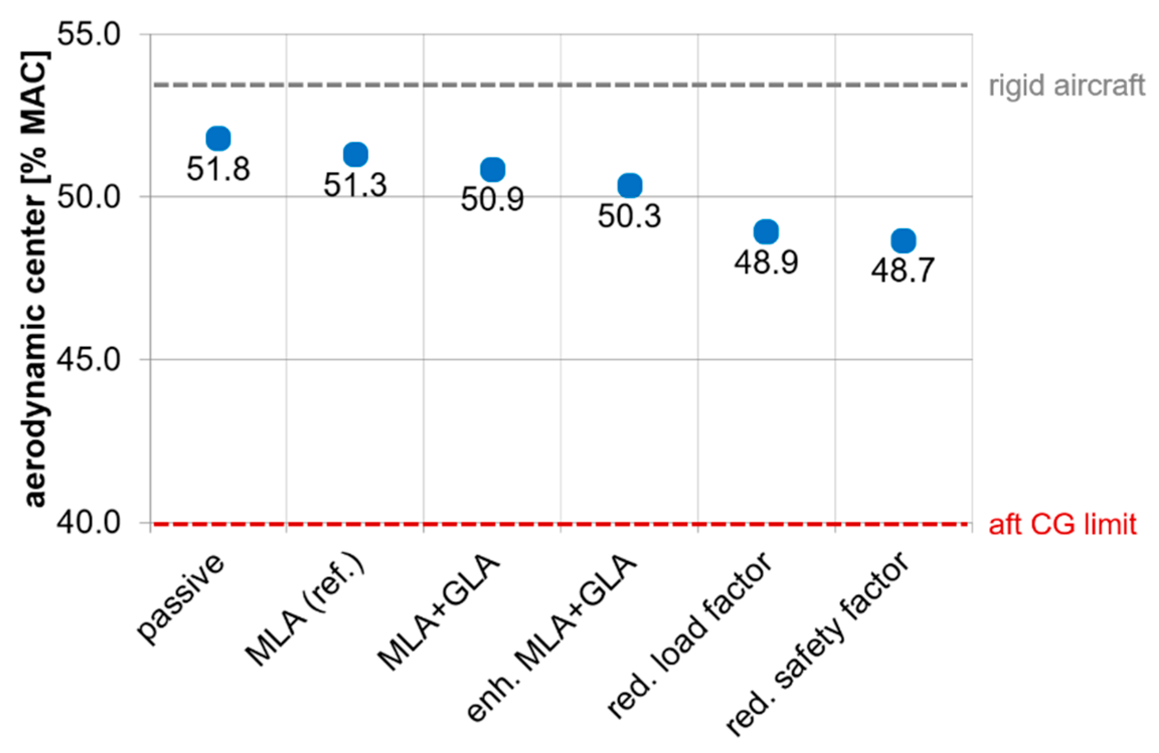
For the longitudinal stability check, the location of the aerodynamic center for all six test cases was calculated using SOL144 at an altitude of approx. 8300 m and at the /. The selected flight condition corresponds to the combination of the highest Mach number and highest dynamic pressure (among those considered in the loads analysis) to evoke well pronounced shifts in the aerodynamic center due to aeroelasticity. Figure 46 shows an overview of the aerodynamic center positions, where that of a rigid aircraft would lie at 53.5% MAC. It is apparent that for all six test cases, the aerodynamic center stayed significantly behind the aft CG limit of 40% MAC, even for the most flexible variant (red. safety factor); thus, it can be assumed that, if the aircraft became unstable at + 15% (up to which an aircraft has to be stable according to CS25.629 [27]), the extent of the resulting instability could be compensated for with future technologies.
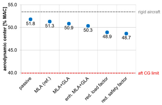
Figure 46.
Overview of the location of the aerodynamic center.
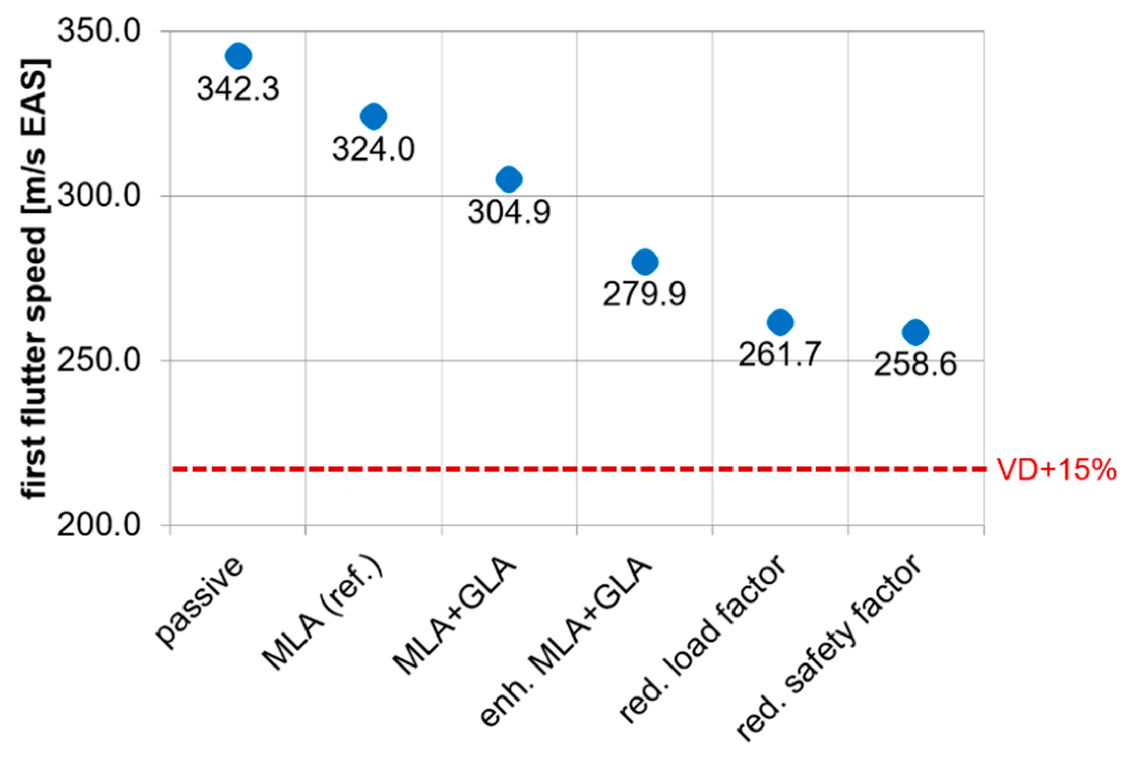
For the subsonic flutter check using the KE-method in SOL145 of MSC.Nastran, the reference altitude was set to sea level. This altitude was selected to be able to reach high dynamic pressures with a relatively low Mach number. The reference Mach number was set to 0.55, which corresponds to the at sea level. Figure 47 shows an overview of the flutter speeds. For all six test cases, the flutter speed was larger than + 15% of approx. 215 m/s EAS (equivalent airspeed); however, it has to be remarked that the flutter calculation was performed in the subsonic regime, and the flutter speed in the transonic regime could fall below + 15% or + 15% on some variants. At this point, it is assumed that future technologies in active flutter suppression will be able to shift the flutter speed back up to + 15% or + 15%.
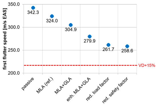
Figure 47.
Overview of the flutter speed.
6. Evaluation, Conclusions and Outlook
6.1. Evaluation
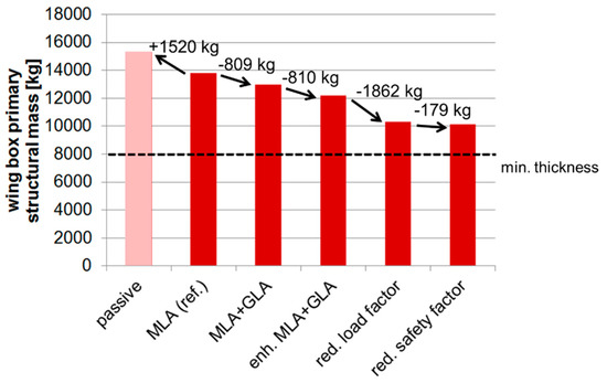
Figure 48.
Overview of the wing box mass reduction.
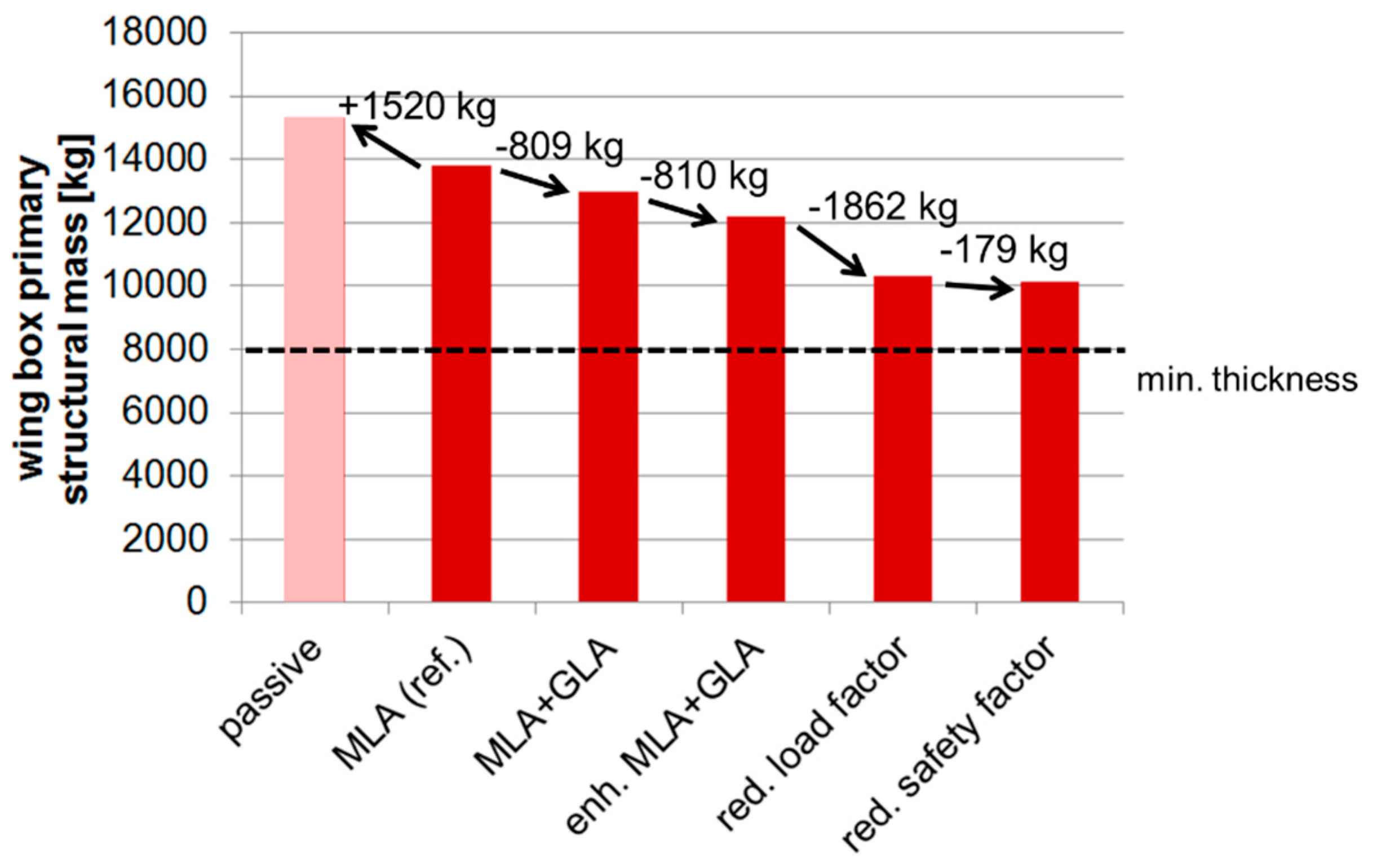
- The MLA on the reference variant already yielded a significant mass reduction of 1520 kg compared to its passive counterpart.
- If the reference were combined with a simple GLA, an 809 kg of mass saving would be obtained.
- An enhanced control surface layout and enhanced MLA/GLA algorithms yielded another 810 kg of mass reduction (the difference between MLA + GLA and enh. MLA + GLA).
- The largest step in the mass reduction by 1862 kg was achieved by reducing the design load factor to 1.5 (between the enh. MLA + GLA and red. load factor).
- A reduction of the safety factor from 1.5 to 1.3 (from the red. load factor to the red. safety factor) did not yield any significant mass reduction since a large portion of the wing box was already at the minimum thickness and could not be made thinner.
- With the inclusion of all future technologies and scenarios, the wing box mass can be reduced by up to 3660 kg (the difference between the reference and the red. safety factor).
- The wing box mass with the minimum thickness (7992 kg) already made up 57.9% of the reference wing box mass (13,803 kg).
The resulting masses from the structural optimization only referred to the ideal load-carrying masses. Additional penalties due to joints, reinforcements, etc., which appear in the manufactured structure were not considered. To take the penalties into account, empirical mass factors were proposed by Chiozzotto [18], and these are to be multiplied with the masses resulting from the structural optimization. Table 2 lists the empirical mass factors derived by Chiozzotto [18].

Table 2.
Empirical mass factors for wing box mass.
With an approximated mass factor for the entire wing box of 1.5, the fraction of the variable mass (primary structure) would increase from ca. 40% to around 60% of the target wing mass of the reference variant. At the same time, the fraction of the additional masses (blue area, as stated in Section 2.2) would decrease significantly, see Figure 49. In other words, the fraction of mass of the yet unknown sources is reduced significantly by implementing the mass factor. The green area represents the secondary masses which are kept constant. In total, if the mass factor is considered in the calculation of the mass changes due to the load alleviation features, then larger nominal changes in the OEM are expected.
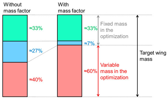
Figure 49.
Increase of the fraction of variable mass with mass factor.
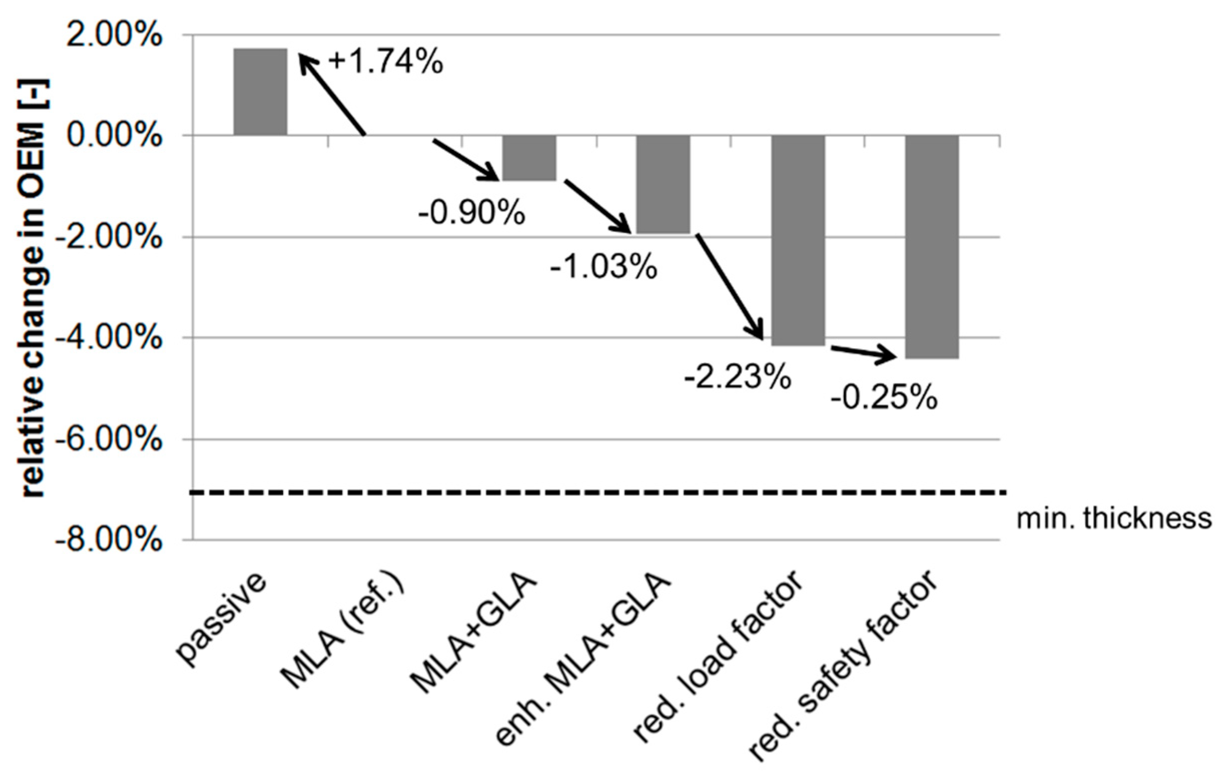
On the overall aircraft level, the mass changes—with consideration of the mass factor—are shown in Figure 50. In this case, mass changes at the HTP and VTP were also taken into account. Additionally, the mass saving on the empennage between the passive and the red. safety factor variant was approx. 240 kg (already including a mass factor of 1.5). It has been shown that with all the future technologies and scenarios, the OEM can be reduced by 4.4% (the difference between the reference and the red. safety factor). A more detailed listing of the masses can be found in Appendix A.
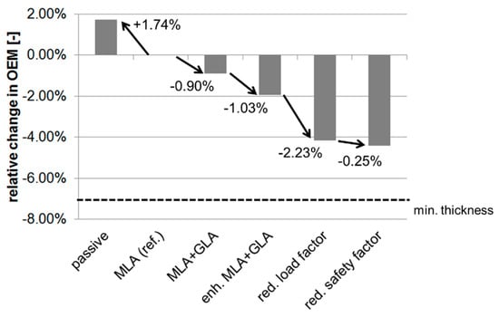
Figure 50.
Overview of the change in OEM.
On the other hand, the HTP design load cases (checked maneuvers)—which are expected to evoke higher loads compared to quasi-steady maneuvers and dynamic gusts—were not considered in the investigation; hence, with a consideration of checked maneuvers, the HTP mass fluctuations would be expected to be lower since the loads of checked maneuvers are not affected by the load alleviation.
6.2. Conclusions
The investigations concerning the potential of mass saving in wing structures using the featured design process have been elaborated. The assumed future technologies applied in the investigations—which benefit the mass saving—range from an enhanced control surface layout, load alleviation algorithms, and a reduced design load factor to a reduced safety factor.
With all the technologies applied, the resulting reduction in the primary structure of the wing box was 26.5%. On the overall aircraft level and by considering the mass factor addressed in Section 6.1, the reduction of the OEM was 4.4%. This also includes the mass changes in the HTP and VTP. Moreover, the following insights emerged during the investigations:
- Among the implemented technologies, the largest mass benefit was obtained through a reduction in the design load factors and the design gust speeds.
- If the structure was already close to the minimum thickness, a further load reduction had no significant effect on the mass.
6.3. Outlook
For the future, checked maneuvers—which are sizing load cases for the HTP—can be taken into account. With that, the HTP mass fluctuation due to the load alleviation is expected to be lower.
An aspect to be considered is fatigue. With a lower structural mass, the fatigue damage due to ground–air–ground cycles are expected to increase, while the fatigue damage during a flight can be mitigated with a load alleviation [22]. If the structural mass decrease is high, however, the increase in the fatigue damage due to the ground–air–ground cycles might outweigh the fatigue damage during the flight, so that the aircraft has an overall shorter fatigue life. Hence, a fatigue analysis is advisable at this point to verify that an aircraft is still able to conduct the number of flight cycles it is designed for.
Furthermore, dynamic load simulations in the time domain, as shown by Hesse et al. [30], can facilitate calculations with a 3D disturbance velocity field (which are, among others, useful for fatigue analysis) and ease an integration of nonlinear controllers. Regarding the controller itself, Hansen et al. [31] proposed a control architecture that decouples the objectives of load alleviation and flight trajectory. The proposed control system can achieve wing load reductions for combined loading conditions (in this case maneuvers and gusts), which are, among others, useful for fatigue analysis.
A further aspect which can be taken into account is the integration of the controller synthesis into the design process, so that the load alleviation, the loads and the structure can be adjusted to each other.
Concerning a further mass reduction in the future, several points can be addressed. For example, the constraints regarding the minimum thicknesses can be re-evaluated. Furthermore, load calculations for the system masses (both leading and trailing edge devices) can be conducted to check whether those components can become lighter along with the wing box.
While the results provide an overview of the potential of the investigated technologies, the influence on the overall aircraft can only be determined if all the snowball effects, such as the configurational aspects including the wing-planform, secondary masses, system-design, etc., are fully considered. As an analysis of all those aspects at a significant level would need substantial effort, an isolated analysis of the first-order aspects, such as those presented in this paper is nevertheless considered valuable to identify beneficial future paths of research.
Author Contributions
Conceptualization, L.T., W.R.K., J.H. and V.H.; methodology, K.B. and V.H.; analysis and investigation, V.H.; visualization, V.H. and K.B.; writing—original draft preparation, V.H.; writing—review and editing, W.R.K., L.T., J.H. and K.B. All authors have read and agreed to the published version of the manuscript.
Funding
This research received no external funding.
Institutional Review Board Statement
Not applicable.
Informed Consent Statement
Not applicable.
Data Availability Statement
Not applicable.
Conflicts of Interest
The authors declare that there is no conflict of interest.
Nomenclature
| frequency [Hz] | |
| second order high pass filter | |
| GLA gain [-] | |
| second order low pass filter | |
| design cruise Mach number [-] | |
| design dive Mach number [-] | |
| time delay | |
| transfer function in general | |
| design maneuvering airspeed [m/s EAS] | |
| design cruise airspeed [m/s EAS] | |
| design dive airspeed [m/s EAS] | |
| gust angle of attack [deg] | |
| GLA deflection [deg] | |
| MLA deflection [deg] | |
| equivalent airspeed [m/s] | |
| CG | center of gravity |
| GLA | gust load alleviation |
| HTP | horizontal tailplane |
| LRA | load reference axis |
| MLA | maneuver load alleviation |
| VTP | vertical tailplane |
Appendix A

Table A1.
Overview of the mass configurations.
Table A1.
Overview of the mass configurations.
| Label | Mass [t] | CG [Ref. Chord] | Remark |
|---|---|---|---|
| MOOee | 130.3 | 0.28 | Operating empty mass |
| MCFfe | 145.7 | 0.18 | Forward CG, lightly loaded |
| MCAae | 145.7 | 0.37 | Rear CG, lightly loaded |
| MHFFe | 169.7 | 0.20 | Forward CG, heavily loaded |
| MHAAe | 169.7 | 0.40 | Rear CG, heavily loaded |
| MZmMe | 178.1 | 0.30 | Central CG, full payload |
| MTFFJ | 245.0 | 0.21 | MHFFe with 75.2 t fuel |
| MTAAJ | 245.0 | 0.34 | MHAAe with 75.2 t fuel |
| MTmMG | 244.8 | 0.28 | MZmMe with 66.6 t fuel |

Table A2.
Overview of the wingbox primary structural mass in kg.
Table A2.
Overview of the wingbox primary structural mass in kg.
| Passive | MLA (Ref.) | MLA + GLA | Enh. MLA + GLA | Red. Load Factor | Red. Safety Factor | min. Thickness | |
|---|---|---|---|---|---|---|---|
| Upper cover | 5921 | 5179 | 4871 | 4495 | 3453 | 3411 | 1995 |
| Lower cover | 5342 | 4704 | 4235 | 3929 | 3275 | 3240 | 3139 |
| Ribs | 2251 | 2179 | 2193 | 2133 | 2040 | 1986 | 1676 |
| Forward spar | 669 | 646 | 571 | 539 | 492 | 492 | 419 |
| Middle spar | 351 | 348 | 344 | 331 | 313 | 309 | 259 |
| Rear spar | 789 | 747 | 779 | 757 | 749 | 705 | 504 |
| Total | 15,323 | 13,803 | 12,994 | 12,184 | 10,322 | 10,143 | 7992 |
| Rel. diff. | +11.0% | 0.0% | −5.9% | −11.7% | −25.2% | −26.5% | −42.1% |

Table A3.
Overview of the operating empty mass in kg.
Table A3.
Overview of the operating empty mass in kg.
| Passive | MLA (Ref.) | MLA + GLA | Enh. MLA + GLA | Red. Load Factor | Red. Safety Factor | min. Thickness | |
|---|---|---|---|---|---|---|---|
| Wing box | 15,323 | 13,803 | 12,993 | 12,184 | 10,322 | 10,143 | 7992 |
| HTP box | 962 | 970 | 1004 | 911 | 835 | 812 | 722 |
| VTP box | 624 | 624 | 622 | 622 | 622 | 614 | 590 |
| Total OEM | 131,842 | 130,330 | 129,552 | 128,650 | 126,712 | 126,502 | 124,237 |
| Rel. diff. | 1.16% | 0.00% | −0.60% | −1.29% | −2.78% | −2.94% | −4.68% |
| Rel. diff. with mass factor | 1.74% | 0.00% | −0.90% | −1.93% | −4.16% | −4.41% | −7.02% |
References
- Hönlinger, H.; Zimmermann, H. Structural Aspects of Active Control Technology. In Flight Mechanics Panel Symposium; AGARD: Turin, Italy, 1994. [Google Scholar]
- Regan, C.; Jutte, C. Survey of Applications of Active Control Technology for Gust Alleviation and New Challenges for Lighter-Weight Aircraft; Dryden Flight Research Center: Edwards, CA, USA, 2012. [Google Scholar]
- Himisch, J. Winglet Shape and Load Optimization with a numerically supported Lifting Line Method. In Proceedings of the 12th AIAA/ISSMO Multidisciplinary Analysis and Optimization Conference, Victoria, BC, Canada, 10–12 September 2008. [Google Scholar]
- Handojo, V.; Lancelot, P.; de Breuker, R. Implementation of Active and Passive Loads Alleviation Methods on a Generic Mid-Range Aircraft Configuration. In Proceedings of the AIAA Aviation Forum, Multidisciplinary Analysis and Optimization Conference, Atlanta, GA, USA, 25−29 June 2018. [Google Scholar] [CrossRef]
- Kenway, G.K.W.; Martins, J.R.R.A. Multipoint high-fidelity aerostructural optimization of a transport aircraft configuration. J. Aircr. 2014, 51, 144–160. [Google Scholar] [CrossRef]
- Kennedy, G.J.; Martins, J.R.R.A. A comparison of metallic and composite aircraft wings using aerostructural design optimization. In Proceedings of the AIAA Aviation Technology, Integration, and Operations (ATIO) Conference and 14th AIAA/ISSM, Indianapolis, IN, USA, 17–19 September 2012. [Google Scholar] [CrossRef]
- Dillinger, J.K.S.; Abdalla, M.M.; Klimmek, T.; Gürdal, Z. Static aeroelastic stiffness optimization and investigation of forward swept composite wings. In Proceedings of the World Congress on Structural and Multidisciplinary Optimization, Orlando, FL, USA, 19–24 May 2013. [Google Scholar]
- Binder, S. Simultaneous Optimisation of Composite Wing Structures and Control Systems for Active and Passive Load Alleviation. Ph.D. Thesis, Technical University of Delft, Delft, The Netherlands, 2021. [Google Scholar]
- Wildschek, A.; Hanis, T.; Stroscher, F. L∞-optimal Feedforward Gust Load Alleviation Design for a Large Blended Wing Body Airliner. Prog. Flight Dyn. GNC Avion. 2013, 6, 707–728. [Google Scholar]
- Bramsiepe, K.; Handojo, V.; Meddaikar, Y.; Schulze, M.; Klimmek, T. Loads and Structural Optimisation Process for Composite Long Range Transport Aircraft Configuration. In Proceedings of the AIAA Aviation Forum, Multidisciplinary Analysis and Optimization Conference, Atlanta, GA, USA, 25–29 June 2018. [Google Scholar] [CrossRef]
- Kroll, N.; Abu-Zurayk, M.; Dimitrov, D.; Franz, T.; Führer, T.; Gerhold, T.; Görtz, S.; Heinrich, R.; Ilic, C.; Jepsen, J.; et al. DLR project Digital-X: Towards virtual aircraft design and flight testing based on high-fidelity methods. CEAS Aeronaut. J. 2015, 7, 3–27. [Google Scholar] [CrossRef]
- Görtz, S.; Abu-Zurayk, M.; Ilic, C.; Wunderlich, T.; Keye, S.; Schulze, M.; Klimmek, T.; Kaiser, C.; Süelözgen, Ö.; Kier, T.; et al. Overview of Collaborative Multi-Fidelity Multidisciplinary Design Optimization Activities in the DLR Project VicToria. In Proceedings of the AIAA Aviation Forum 2020, Virtual Event. 15–19 June 2020. [Google Scholar] [CrossRef]
- Bertram, O. Nekon—Neue Entwurfsmethoden Zukünftiger Steuerflächenkonzepte (im LuFo V.2 Con.Move-Verbundprojekt); Project Report DLR-IB-FT-BS-2020-232; Deutsches Zentrum für Luft- und Raumfahrt: Braunschweig, Germany, 2020. [Google Scholar]
- Klimmek, T.; Schulze, M.; Abu-Zurayk, M.; Ilic, C.; Merle, A. cpacs-MONA—An Independent and in High-Fidelity Based MDO Tasks Integrated Process for the Structural and Aeroelastic Design of Aircraft Configurations. In Proceedings of the International Forum on Aeroelasticity and Structural Dynamics, Savannah, GA, USA, 9–13 June 2019. [Google Scholar]
- Klimmek, T. Parametric Set-Up of a Structural Model for FERMAT Configuration for Aeroelastic and Loads Analysis. ASD J. 2014, 2, 31–49. [Google Scholar]
- JJsselmuiden, S.I. Optimal Design of Variable Stiffness Composite Structures Using Lamination Parameters. Ph.D. Thesis, TU Delft, Delft, The Netherlands, 2011. [Google Scholar]
- Klimmek, T. Statische Aeroelastische Anforderungen beim Multidisziplinären Strukturentwurf von Transportflugzeugflügeln. Ph.D. Thesis, Deutsches Zentrum für Luft- und Raumfahrt, Göttingen, Germany, 2016. [Google Scholar]
- Chiozzotto, G. Improving Aircraft Conceptual Design with Methods for Wing Loads, Aeroelasticity and Mass Estimation. Ph.D. Thesis, TU Berlin, Berlin, Germany, 2019. [Google Scholar]
- Torenbeek, E. Development and Application of a Comprehensive, Design-Sensitive Weight Prediction Method for Wing Structures of Transport Category Aircraft; Report LR-693; TU Delft: Delft, The Netherlands, 1992. [Google Scholar]
- Albano, E.; Rodden, W. A Doublet Lattice Method for Calculating Lift Distributions on Oscillating Surfaces in Subsonic Flows. In Proceedings of the AIAA 6th Aerospace Sciences Meeting, New York, NY, USA, 22–24 January 1968. [Google Scholar]
- MSC.Software Corporation, MSC.Nastran Version 68—Aeroelastic Analysis User’s Guide, MSC.Software. Available online: https://simcompanion.hexagon.com/customers/s/article/aeroelastic-analysis-user-s-guide-doc9182 (accessed on 29 April 2022).
- Handojo, V. Contribution to Load Alleviation in Aircraft Pre-Design and Its Influence on Structural Mass and Fatigue. DLR-FB-2020-47. Ph.D. Thesis, DLR Institut für Aeroelastik, Göttingen, Germany, 2020. [Google Scholar]
- Tetlow, R. Design Charts for Carbon Fibre Composites; Technical Report; Cranfield Institute of Technology: Cranfield, UK, 1970. [Google Scholar]
- Schlichting, H.; Truckenbrodt, E. Aerodynamik des Flugzeuges, Zweiter Band; Springer: Berlin/Heidelberg, Germany, 1969. [Google Scholar]
- Federal Aviation Administration. Statistical Loads Data for the Boeing 777-200ER Aircraft in Commercial Operations, Report DOT/FAA/AR-06/11. Available online: http://www.tc.faa.gov/its/worldpac/techrpt/ar06-11.pdf (accessed on 29 April 2022).
- Handojo, V.; Klimmek, T. ALLEGRA Meilensteinbericht M3.3.2: Böensimulation des Elastischen Flugzeugs mit Basisverfahren; DLR Institut für Aeroelastik: Göttingen, Germany, 2015. [Google Scholar]
- European Aviation Safety Agency, CS25—Certification Specifications and Acceptable Means of Compliance for Large Aeroplanes-Amendment 23. 2019. Available online: https://www.easa.europa.eu/sites/default/files/dfu/CS-25_Amdt%203_19.09.07_Consolidated%20version.pdf (accessed on 29 April 2022).
- Reckzeh, D. Multifunctional Wing Moveables: Design of the A350 XWB and the Way to Future Concepts. In Proceedings of the 29th Congress of the International Council of the Aeronautical Sciences, St. Petersburg, Russia, 7–12 September 2014. [Google Scholar]
- US Department of Defense. MIL-STD-1797A—Flying Qualities of Piloted Aircraft. Report MIL-STD-1797A. 2004. Available online: https://engineering.purdue.edu/~andrisan/Courses/AAE490F_S2008/Buffer/mst1797.pdf (accessed on 29 April 2022).
- Hesse, H.; Palacios, R. Dynamic load alleviation in wake vortex encounters. J. Guid. Control Dyn. 2016, 39, 801–813. [Google Scholar] [CrossRef]
- Hansen, J.H.; Duan, M.; Kolmanovsky, I.V.; Cesnik, C.E.S. Load Alleviation of Flexible Aircraft by Dynamic Control Allocation. J. Guid. Control Dyn. 2022; article in advance. [Google Scholar] [CrossRef]
Publisher’s Note: MDPI stays neutral with regard to jurisdictional claims in published maps and institutional affiliations. |
© 2022 by the authors. Licensee MDPI, Basel, Switzerland. This article is an open access article distributed under the terms and conditions of the Creative Commons Attribution (CC BY) license (https://creativecommons.org/licenses/by/4.0/).

