1. Introduction: SoA, Starting Point, and Motivation
In aircraft design, the concept of aeroelastic tailoring can be defined as the directional stiffness strategy to control the static and dynamic aeroelastic phenomena, to advantageously affect the aircraft’s behavior and safety [
1]. Aeroelastic tailoring developed as a result of advances in two technological fields: fibrous composite materials and mathematical programming methods. On the one hand, certainly, the composite materials meaningfully increased aircraft structural design options. In particular, the orthotropic features of composites and their directional stiffness and strength properties, determined through the assembly or stacking sequence of the lamina and the high stiffness-to-weight ratio, offer design solutions that are often not available with conventional metallic materials. On the other hand, a composite laminate needs the determination of the number of plies and the orientation of each ply, leading to increased design complexity.
The term aeroelastic tailoring was coined in 1969 when General Dynamics submitted a proposal to the Air Force Flight Dynamics Laboratory [
2,
3] to apply advanced filamentary composite materials to the design of a supercritical wing to improve transonic performance by offering the best wing design solution at both cruise and maneuver conditions. Other than the weight savings, the driving factor behind the ambitious objective was the application of advanced composites that had directional properties that could be used to provide a noteworthy level of anisotropy to produce coupling between bending and twisting deformation. This coupling created the wanted silhouette control for the supercritical wing.
Structural optimization and aeroelastic tailoring are very attractive from a research point of view due to the very directional nature of a composite structure (the stacking sequence and the thickness of the laminates are typical design variables in the optimization) and can expand the envelope of opportunities to bring in more complex performance constraints. In addition, these activities have strong industrial implications, since they allow for the minimization of weight and/or operating costs. Nevertheless, they require a strong multidisciplinary approach that involves different expertise groups, such as aeroelasticity, dynamics, loads, weight management, and flight mechanics and structures, with the main purpose of having a wing that fulfils all the requirements at the minimum weight, without compromising flight safety. The first occasion to apply aeroelastic tailoring with composite materials was provided by the Transonic Aircraft Technology program. The scope of this program was to obtain efficient aerodynamic performance at both cruise and high-g maneuver conditions. To maximize wing aeroelastic twist from 1 g to the desired g while maintaining weight savings, anisotropy was provided by composite cover skins [
4]. The wing shape at supersonic cruise was a dominant design requirement, because it has a direct impact on mission performance and take-off gross weight. By employing this application, it was shown that material bend/twist coupling variations have a greater effect than variations in box chord dimensions. J. Green [
5] studied the aeroelastic performance of aft-swept high-aspect-ratio wings as a function of the fiber angle and dimensionless modulus parameters. The aeroelastic problem was solved by using a state vector formulation and incorporating the integrating matrix technique. The results were shown for a reference laminate and several different ply orientations including nonsymmetric laminates, with the effects of both ply orientation and modulus included. From the study, it was determined that extension-torsion coupling caused some degradation of the flutter boundary, whereas extension-bending coupling had a less severe effect, resulting in a flutter boundary that was as good as the best symmetric laminate with the same torsion-bending stiffness. Eastep [
6] performed a composite wing design optimization study in which multilevel optimization was used. Starting from a baseline layup (0, 90, ±45), the angle of the layup orientation was varied (with increments of 5 degrees up to 20 degrees) with respect to a specified reference axis. Different studies were conducted to evaluate the effects of the layup orientation of the composite skins on the optimized wing weight by using constraints on strength, aileron efficiency, and flutter characteristics. The studies were conducted in an incremental way, starting from strength constraint, then roll-reversal velocity and, finally, flutter. It was shown that the optimal designs of the wing under study were relatively insensitive to the orientation of the laminate layup when the wing was subjected to multiple structural constraints. Chang et al. [
7] optimized a swept-back composite wing box investigating the effect of different thickness distributions of the top and bottom skins along the span. They performed a first optimization by means of the multi-island genetic algorithm (MIGA) for maximum flutter velocity, obtaining optimal layups characterized by nonorthodox ply angles. Then, they performed a further loop of optimization by considering, simultaneously, flutter speed and stiffness. In general, they proved the effectiveness of composite tailoring on augmenting the flutter stability margin; nevertheless, the authors reported that the design variable scheme, which considers manufacturing accuracy errors, multiload cases, and multi-objectives, should be paid more attention to for further improvement. Dillinger et al. [
8] presented an efficient method for composite wing (A320-like) stiffness optimization with aeroelastic constraints by considering the mass, strength, buckling, aerodynamic twist, and aileron effectiveness. The elements of the in-plane and bending stiffness matrices and laminate thicknesses were used as design variables. The optimizer was shown to yield efficient convergence behavior for mass and aileron effectiveness optimizations, and the advantage of unbalanced overbalanced laminates was elaborated. A recent study regarding aeroelastic tailoring [
9] focused on evaluating how the introduction of continuous blending constraints affects the optimum design and retrieval of the final stacking sequence of a regional aircraft wing. The design variables used in the optimization were the wing box panel thickness and composite anisotropy characteristics. Furthermore, continuous blending constraints were incorporated inside the optimization. Several static and dynamic loads at various flight and mass conditions were considered in the study as well as the potential weight savings due to the implementation of a maneuver load alleviation (MLA) strategy.
The present work was developed within a European-funded project named T-WING. T-WING is aimed at the development—until experimental flight test—of a composite wing, moveable surfaces, and the metallic nacelle primary structure of the Next Generation Civil Tilt Rotor Technology Demonstrator (NGCTR-TD) under development within the Horizon 2020 Clean Sky 2 FRC IADP (Fast RotorCraft Innovative Aircraft Demonstrator Platform) funding framework, led by Leonardo Helicopters Division (LHD). The vehicle represents one of the two integrated aircraft technology demonstrators foreseen by the Clean Sky 2 program, which is planned to be flown in 2023. NGCTR-TD is a tiltrotor that will extend beyond the current state-of-the-art technology for this category of aircraft. The innovative tiltrotor will be characterized by a series of innovative key technology features such as a split gearbox architecture for a rotor shaft tilting mechanism that allows for the adoption of a non-tilting engine, a fully fly-by-wire control system, an innovative fuel system, and a dedicated wing design with a highly integrated composite structure that maximizes the embarked fuel capacity and the torsional stiffness through a nonconventional curved aft spar configuration. At the time of writing, the wing and main subsystems had passed the critical design reviews (CDRs).
The T-WING’s structural design is performed by complying with the design requirements of minimum weight and flight mechanics and safety requirements such as buckling, strength, and aeroelastic stability. The internal structure of the NGCTR-TD wing, including its structural layout and size, is significantly affected by the aeroelastic and flight mechanics requirements. Indeed, careful consideration of mutual interaction among aerodynamics, structural stiffness, and inertia, all contributing to the aeroelastic problems, mitigates the risk of unexpected detrimental effects on structural safety and or vehicle performance.
Among all of the aeroelastic phenomena that must be addressed, whirl flutter is a fundamental design challenge for the development of a new tiltrotor. This phenomenon, originally encountered on propeller driven aircrafts, is an aeroelastic instability that can arise when the propeller/proprotor operates in axial flow, and its coupled motion with the wing-pylon structure can cause unstable vibration, leading to failure of an engine installation or an entire wing.
For a propeller driven aircraft, the elastic modes of the system are coupled with the gyroscopic effects of the large rotating masses, resulting in complex mode shapes of the entire mechanical system. Considering propeller rotation, the pitch and yaw mode shapes merge in the whirl motion: the system movement becomes a gyroscopic motion, and the propeller axis shows an elliptical movement. In certain conditions, aerodynamic forces produced by the elastic movement of the rotor can trigger a mechanism of energy transfer to other vibration modes, reducing the stability margin of the whole system as higher flight speed and, thus, dynamic pressures are approached, potentially leading to instability and, consequently, hazardous or even catastrophic events.
For a tiltrotor the problem becomes even more complex due to the architecture of the proprotor with its large and flexible blades and their flapping degree of freedom, necessary to control the aircraft when it acts as a helicopter. The dynamics of the proprotor blades play an important role in the description of this phenomenon, and this leads to the necessity of using comprehensive multibody tools (e.g., Camrad II) to conduct high-fidelity whirl flutter analysis.
This article is a continuation of former works [
10,
11] in which a two-level optimization of the composite wing of the Next Generation Civil Tiltrotor—Technological Demonstrator (NGCTR-TD) was presented.
The first-level optimization was based on engineering models, used to perform a multi-objective optimization with the aid of genetic algorithms, also taking into account the aeroelastic stability [
10]. The first-level optimization aimed at having, at the very beginning of the project (the concept design level), a safe structural configuration, free from flutter at minimum mass. The second-level optimization was based on a 1D-2D element finite element model [
11], built based on the solution selected from the first-level structural optimization. The main requirements feeding the design of the wing regard the frequency placement of the selected wing structural modes and flutter clearance, whereas the output of the process is the optimal wing design, which minimizes weight and is compliant with strength and buckling requirements. This process is implemented based on two loops of analysis at different levels of fidelity in the analysis.
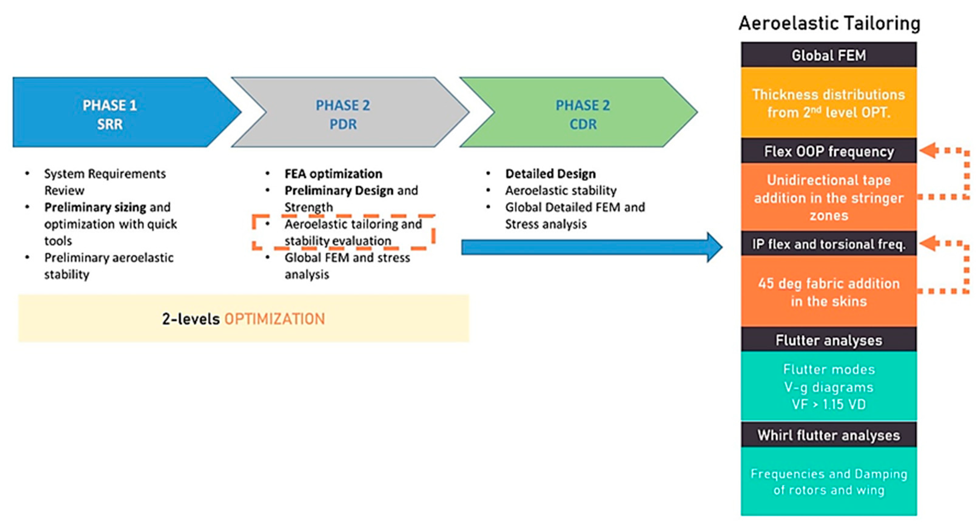
The aeroelastic tailoring phase of the wing of the NGCTR-TD, which was performed after the two-step optimization, is one of the most delicate phases of the T-WING design activity. During this phase, beam-like wing models are abandoned in favor of more complex and higher-fidelity FE models aimed at evaluating aeroelastic instabilities such as flutter and whirl flutter. Specifically, for a prescribed wing structural architecture (i.e., rib spacing and the chord-wise position of spars and stringers), using composite materials, by varying the thickness and the laminate layup, it is possible to isolate and tune wing bending and torsion frequencies to improve aeroelastic stability margins.
Regarding tiltrotors wing, Nixon et al. [
12] applied aeroelastic tailoring both to the composite wing and the blades of a tiltrotor. In particular, four unique aeroelastic tailoring concepts were studied: (1) bending-twist coupling in the wing to augment the whirl flutter stability margin in the high-speed airplane mode; (2) bending-twist coupling in the wing to augment the aeromechanical stability of soft-in-plane rotor systems under ground and air resonances; (3) bending-twist coupling in the rotor blades to augment the whirl flutter stability margin in a high-speed airplane mode; (4) extension-twist coupling in the rotor blades to optimize their twist distribution between hover and cruise. The studies conducted to augment the whirl flutter stability margin showed that both wing and blade tailoring was effective; whereas for the other studies, additional efforts are needed to assess the feasibility of the concepts. Tiltrotor whirl flutter speed optimization was developed in a recent study in a parametric way [
13]. Wing parameters, such as stiffness, composite materials and wing architecture (i.e., aspect ratio and structural tapering ratio), and winglet parameters (i.e., stiffness, sweep, and cant angle) were identified as key design variables to improve the aeroelastic behavior. The genetic algorithm, a non-gradient-based search method, which has the advantage of being able to find multiple optimal solutions in multi-objective problems, was able to determine an optimal configuration improving the whirl flutter speed by 22.5%. Other theoretical experiences aimed at the design of a future civil tiltrotors were performed by NASA on very heavy civil tiltrotors, called Large Civil Tilt Rotor (LCTR1 and LCTR2) in [
14,
15,
16]. They were studied to meet future commercial transportation requirements. In particular, LCTR2 is a swept rectangular high wing, which has the entire tilting engine nacelles and engines, with gross weights well over 107,500 lb.
The present work focused on the aeroelastic tailoring of the NGCTR-TD wing by means of modal strain energy analysis, which has been used to select the areas of the structure eligible for structural improvement, thus ensuring that the increase in the wing box structure’s thickness is performed by minimizing the weight penalty. The paper is organized as such: (i)
Section 1 highlights the main aeroelastic stability and dynamics requirements and the wing design process flow; (ii) in
Section 2, the models for strength, aeroelasticity, and whirl flutter analysis are presented; (iii)
Section 3 describes the aeroelastic tailoring process; (iv)
Section 4 provides the final results and considerations.
2. Materials and Methods
2.1. Requirements and Process Flow
The standard aeroelastic stability requirements envisaged by the Civil Aviation Rules and the design-specific requirements of NextGen have been translated into targets on low-frequency elastic modes in terms of frequencies and mode shapes (aimed at minimizing unwanted coupling of aeromechanical and rotoric interaction of the wing). Despite the optimization activity devoted to ensuring minimum strength, buckling, and stiffness capacity for the wing, it was necessary, also, to begin an aeroelastic tailoring activity to match the minimum out-of-plane (OOP) flexural frequency of the wing and sufficient margins on the in-plane (IP) and torsional modes (symmetrical and antisymmetrical modes) to be compliant with the requests coming from whirl flutter stability envelope. This activity was necessary to minimize the impact on the wing’s structural mass, since the composite material to be used was selected based on available and already certified materials.
The research was oriented to determine an efficient method that allowed to cover the aeroelastic requirements using an uncoupled approach in which the whirl-flutter frequencies requirements were translated into stiffnesses requirements that represented the target of the final wing design. Nevertheless, the need to increase the global stiffnesses in a structure like a wing could have a huge weight penalty. To identify the wing region to add the specific composite layers, modal strain energy analysis was employed.
Figure 1 illustrates the three main phases of the wing design with a special focus on aeroelastic tailoring.
In the present chapter, a brief overview of the materials used for the wing design as well as the models that were built to allow for the requirements of compliance assessment is presented.
2.2. Materials
A carbon fiber epoxy resin in the form of both fabric and tape was used for wing sizing. Different layups associated to each zone were considered, all based on typical ply angles (0, 90, ±45). A maximum of two plies with the same orientation angle were put directly together. The ply stacking sequences were as symmetrical as possible with respect to the mid-plane of the laminate. The number of plies were designed to meet the strength and aeroelastic requirements passing from a minimum in the tip rib zone to a maximum in the wing to fuselage attach cross-section. By using the same typical angles and type of material (tape/fabric), the enhancement of the aeroelastic requirements, as an objective during the two-level optimization, was performed by following a tailored approach. This was achieved by seeking the optimal structural properties of the composite wing, including bending and torsional stiffness, by using both fabric and unidirectional tape. Cross-sectional parameters, such as the ply orientation angles and laminate thickness, were properly modified to gain aeroelastic stability as the final purpose. The abovementioned methodology led to the consideration of hybrid layups to ensure the wing’s structural and elastic properties. The material’s mechanical properties are reported in
Table 1 for ease of reference.
2.3. Models for Strength Analysis
The finite element model used for the strength and buckling verifications was developed by MSC Nastran, and it is a global FEM, meaning that it comprises not only the wing structure but also the remaining subsystems of the vehicle as super-elements or concentrated masses (i.e., fuselage, wingtip nacelles, tail, systems hosted in the wing, and fuel mass). The wing FE model is characterized by 2D (TRIA and QUAD) elements for the wing’s upper and lower skins, stringers, spar webs, and ribs; 1D (CROD) elements for caps. The RBE3 elements have the function to transfer loads to the structure (inertial and aerodynamics). Suitable RBE2 elements simulate the structural links at the wing–fuselage junction.
For composite element properties, PCOMP cards and the 2D orthotropic material MAT8 were used. PSHELL and MAT1 cards were for isotropic material parts (metallic parts). The model was loaded by means of a no. 50 sizing load conditions that included aerodynamic loads, propulsion forces at the nacelle prop-rotor location, fuselage and tail balancing forces, and inertia loads applied to the model to counteract the external loads. In order to verify the consistency of the loaded stress model with the model used to generate the loads, the accelerations and output of the structural analysis were compared with the given accelerations foreseen by the loads model, highlighting a very good match. The FEM was characterized by a coarse mesh (mean mesh size of 2.0 in), which has subsequently been replaced, for strength and buckling by a detailed global FEM (DFEM) to allow for higher fidelity stress analysis. An image of the model can be found in [
11].
2.4. Aeroelastic Model
In typical aeronautical applications, finite element models employed for structural dynamics and aeroelasticity are usually simplified models (stick-beam like, for example) with respect to the ones used for stress analysis, since the physical content is well described by few vibration modes of interest for the specific phenomenon. This is true especially for the preliminary phases of the design, when the simulations must be computationally cost effective to allow for multiple iterations and to refine the requirements for the successive detailed design phases. More refined finite element models were used once the high-level design architecture was frozen, and the dynamics and aeroelastic assessments can supply indications for improvement in the design of specific structural components, if needed.
In the framework of the NGCTR-TD design, several typologies of models were developed with different levels of detail and modal resolutions according to the requirement of the representativeness level imposed by the scope of the analyses. In supporting the whirl flutter analysis, higher-fidelity models were typically used whenever possible in order to increase the representativeness of the aircraft global mode shapes, especially at the rotor–wing structural points of interactions. In particular, a shell elements-based GFEM model of the whole aircraft was developed specifically to support this purpose. In this sense, the aeroelastic tailoring activity conveniently exploited such a necessity: the shell-based dynamic Nastran model allows to directly intervene on the composite structure properties with the use of PCOMP cards, so that in the optimization loops both static and dynamic analysis (i.e., modal analysis and aeroelastic analysis) were performed on the same model without resorting to multiple software interfaces. In the following, a particular version of the aforementioned GFEM is presented as the model developed to allow for the integration of the high-fidelity wing model with the condensed and undisclosed representation of the rest of the aircraft.
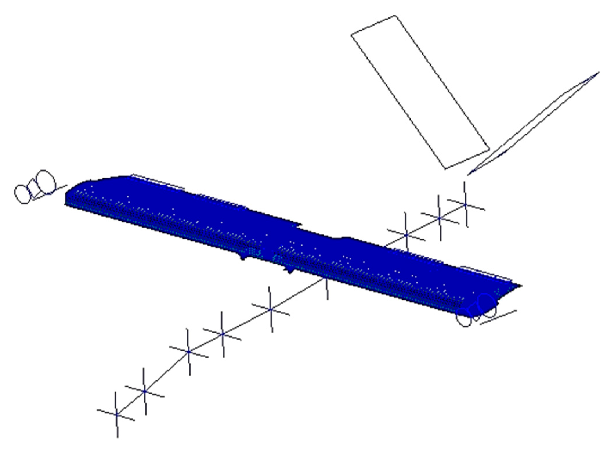
The dynamic part of the model, shown in
Figure 2, consists of different components: wing, two flaperons, and two additional rotating surfaces—actuated during hovering to reduce the downwash effect (so-called “morphing” of moveable surfaces)—fuselage, nacelles, and tail. The structural model was developed as a hybrid model. In fact, while the wing and movable surfaces were modeled as a 3D finite element model assembled by the use of 1D and 2D structural elements (e.g., beams, bars, and quads), all other vehicle components, such as the fuselage, tails, and nacelles, of the NGCTR-TD are represented by Nastran super-elements.
The 3D FEMs of flaperons and morphing surfaces were connected to the fixed part of the airframe by the use of a detailed model that simulated the kinematics of the actuation chain of the moveable surfaces, with bar elements representing the actuators.
The wing’s structural model makes use of concentrated masses, representing the following components applied in a spanwise direction at the geometric centers of gravity of each wing bay:
Wing structure mass;
Fuel mass;
Systems mass.
Each concentrated mass corresponds exactly to the mass of the bay.
The aerodynamic model was defined to run analyses with the doublet lattice method [
17,
18]. This aerodynamic method, based on the linearized potential flow aerodynamic theory, is the extension to unsteady flows of the steady vortex lattice method.
An aerodynamic mesh was spread over the wing and the tail surfaces, represented by flat panels.
Fuselage and nacelles were modeled with perpendicular flat panels, creating crosses, in order to better represent, in addition to the vertical aerodynamic contribution, the lateral aerodynamic loads induced by their volumetric aeroshape.
A numerical tuning was performed to increase the fidelity and consistency of the model by scaling the areas of each aerodynamic panel, by acting directly on the AIC (aerodynamic influence coefficients) matrix with the use of weighting factors. The tuning was implemented targeting the experimental data made available as an output of a wind tunnel test campaign previously conducted with a 3D WT model at the large wind tunnel facility of Politecnico di Milano.
The matching between the dynamic model and the aerodynamic model was implemented with the use of infinite plate splines [
19,
20].
2.4.1. Introduction to Whirl Flutter Instability
Whirl flutter instability was analytically discovered by Taylor and Browne in 1938, but the phenomenon acquired practical and deep experimental attention only after the two fatal accidents that involved the Lockheed L-188 Electra II aircraft on 29 September 1959, in Texas, and on 17 March 1960, in Indiana [
21,
22,
23,
24,
25,
26,
27]. For what concerns tiltrotors, this type of instability is of higher concern; they employ articulated rotors or hinged blade propellers to guarantee vertical flight. For this reason, they are commonly referred to as “proprotors”, and significant efforts at understanding whirl flutter have been made since the very early stages of the technological development of such an aircraft [
28].
Since its beginning, the Bell XV-3 program has suffered from the pylon whirl problem. Teams succeeded in performing the full conversion in 1959, after a series of problems encountered during the first flights. Huge analytical and experimental efforts were dedicated to explaining and possibly correcting the whirl flutter problems of the XV-3 [
29]. During the last part of the full-scale test of the Bell XV-3, conducted at Nasa Ames [
30], suddenly both pylons separated from the wing and were blown down the tunnel, seriously damaging the aircraft and the wind tunnel. It initially appeared as a dynamic pylon instability, but after investigation, it was found that it failed under a whirl divergence condition due to the presence of fatigue crack and rivets working loose in the left wingtip spar, which began involving the left pylon and, after, due to the excessive loads on the right side, the right pylon just after. Notwithstanding all these issues, the XV-3 project demonstrated the ability of the tilt rotor aircraft to perform in-flight conversion and back to the helicopter mode in a safe, stable, controllable manner.
The extensive experimental work of the Bell XV-3 program ultimately made possible the identification of solutions to the high-speed aeroelastic stability problem, thus paving the way for the development of a new tiltrotor, the Bell XV-15 research aircraft, which demonstrated that the primary proof-of-concept objectives were successfully completed. This included validation of rotor/pylon/wing dynamic stability, performance, and noise; nevertheless, in one of the last demonstration flights, a crash accident occurred [
31]. The experience gained in the tiltrotor experimental development made it possible for Bell (in conjunction with its former competitor Boeing) to initiate the V-22 military program. Considerable improvements in the analytical prediction of whirl flutter stability were made by the time the XV-3 was developed, and a number of studies were performed to enhance the XV-22′s stability [
32,
33,
34].
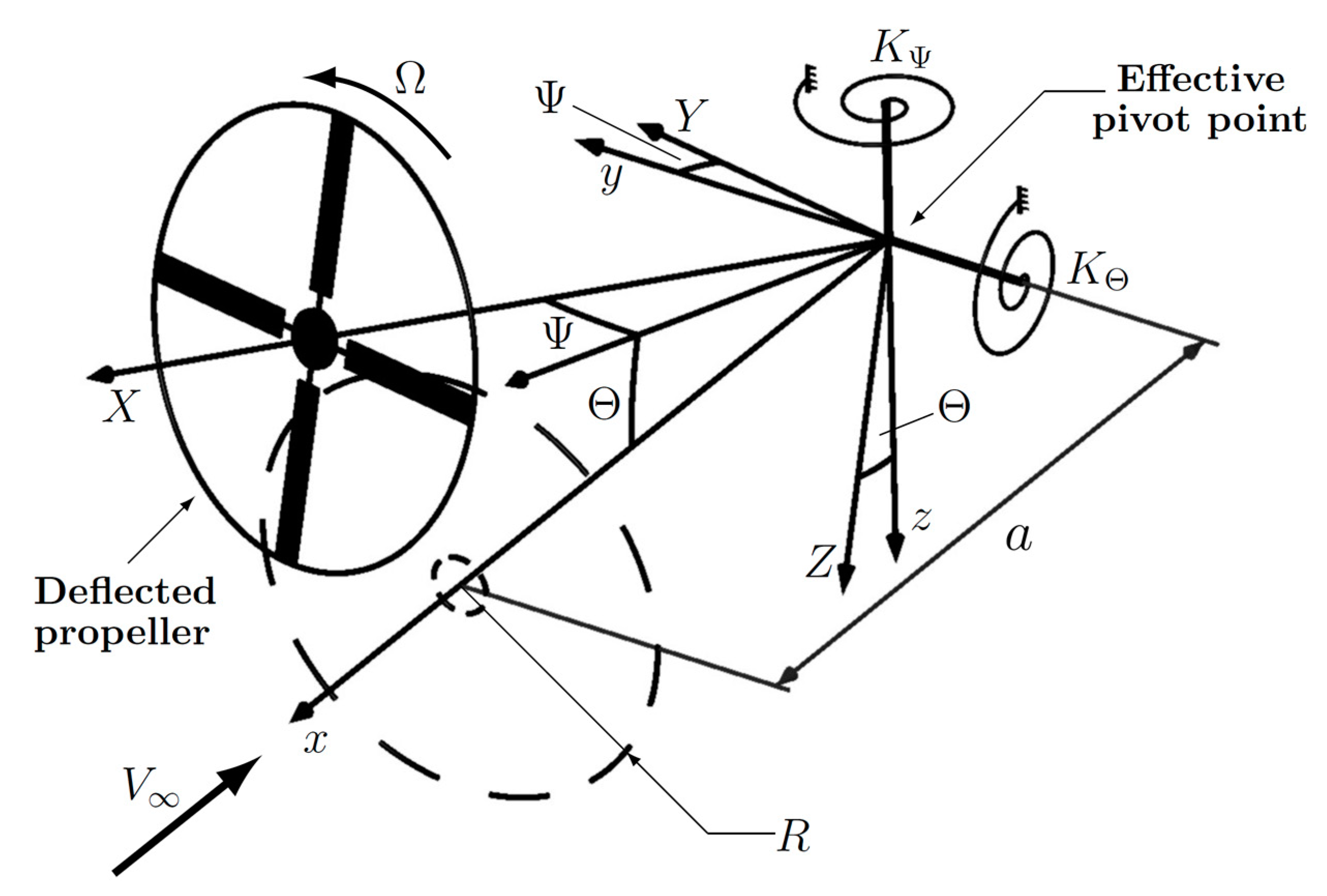
Figure 3 introduces a high-level overview of the whirl flutter phenomenon [
35]. It shows a simplified scheme (2 degrees of freedom model) in which a power plant or nacelle is idealized by two springs behind the propeller disk. The dynamic system can be modeled by means of a propeller with radius R and with the spin axis oriented approximately toward the direction of the freestream velocity, V
∞, and horizontally supported by a pylon pivoted on the wing.
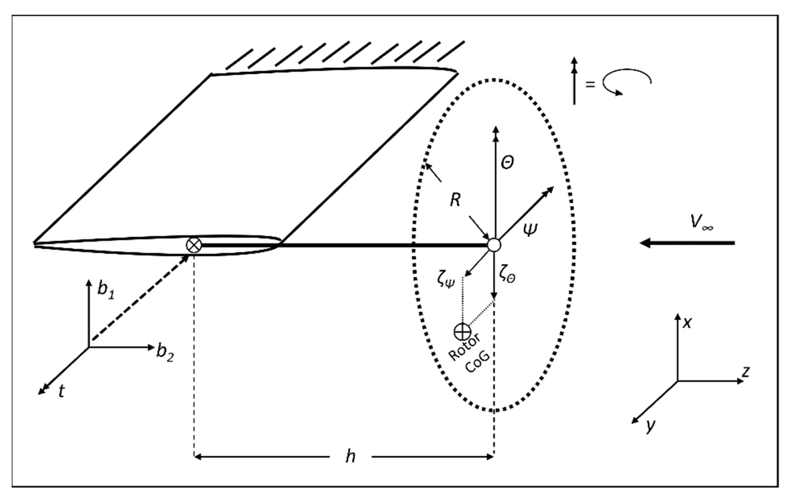
If the propeller has a certain angular velocity, Ω, the two independent mode shapes of pitch and yaw merge into the whirl motion; the propeller axis is subjected to an elliptical motion and the orientation relative to its rotation is such to be backward for the lower frequency mode and forward for the higher frequency one. If the system is not suitably stiffened and, therefore, able to dampen the oscillations, these are amplified with fatal consequences. The research today focuses on nonlinearities (e.g., free play in the tilting mechanism), and for such research purposes, more advanced models are used, which catch the rotor–nacelle system with higher fidelity and features a gimballed hub, rotor blade dynamics, and wing degrees of freedom [
36]. For a gimballed hub model, a gimballed hub connects the rotor to the end of the shaft, allowing the rotor disc to pitch and yaw separately from the motion of the wing. The cyclic lead-lag is modeled as the position of the rotor’s center of gravity within the hub plane that occurs due to the sum of blade’s lead-lag motion. In the scheme reported in
Figure 4, a generic rotor of radius, R, spins with angular velocity, Ω, at the end of a shaft of length h. Where b1 and b2 are, respectively, the beam-wise bending and chord-wise bending; t indicates the torsion; Θ and Ψ are the gimbal pitch and yaw degrees of freedom; ζΘ and ζΨ are the coordinates of the rotor’s center of gravity within the hub plane that occurs due to the sum of the blade’s lead-lag motion, parallel, respectively, to the global
x-axis and
y-axis.
2.4.2. Whirl Flutter Models
For this work, an assessment of the whirl flutter stability margins was performed with the use of the aeroelastic code Camrad II [
37]. This code permits to build a detailed tiltrotor model able to reproduce the aeroelastic behavior of both rotors and their interactions with the drive train and the airframe structure.
The rotor aeroelastic model had the following main characteristics:
A No. 3 blades linked together by means of a yoke element;
The blades and the yoke were modeled by means of a series of 1D beam elements that reproduced their inertial and structural properties;
The blades’ chords, twist, airfoils distributions, and characteristics, in the form of C81 tables, were used to evaluate the aerodynamic forces by means of a lifting line approach;
The rotor pre-cone, δ3, and control chain stiffness were modeled to properly reproduce the rotor’s basic dynamics;
The rotor gimbal degrees of freedom (i.e., pitch and yaw) were modeled to properly reproduce the interaction with the underneath structure.
The drive train model, based on lumped stiffness and inertias, was able to reproduce the frequencies and modes shapes of the low-frequency drive train modes that could participate in the whirl flutter phenomenon.
The airframe structure was included in the aeroelastic model by means of modal information obtained from the linear analysis performed with the complete structural FEM, presented in the previous chapter.
The modal mass, frequency, and mode shapes of each airframe mode at the rotors and swashplate centers were considered in the model.
3. Aeroelastic Tailoring: Main Results and Discussion
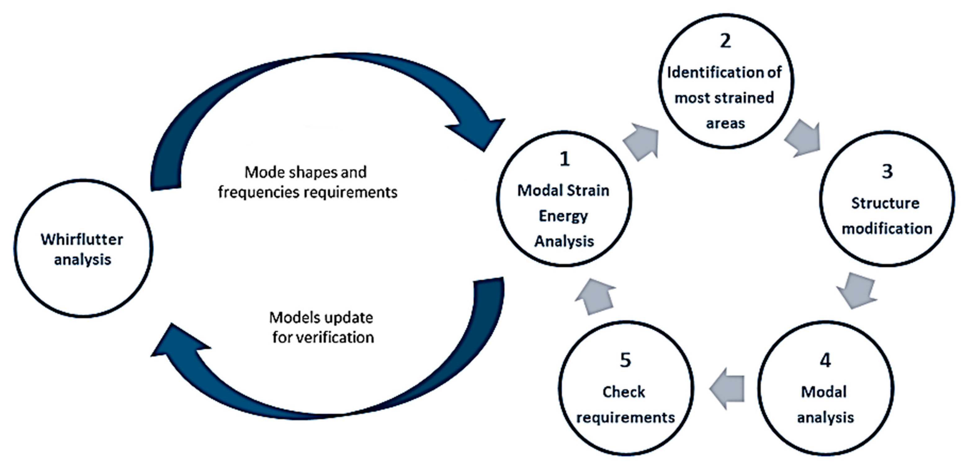
The aeroelastic tailoring process is schematized in
Figure 5. Whirl flutter analysis was performed to generate and refine the requirements expressed in terms of shape and frequency placement of the fundamental elastic vibration modes of the aircraft. With the baseline model, the modal strain energy analysis was used to identify, for each vibration mode of interest, the areas of the wing structure with the highest deformation energy that were consequently eligible for structural improvement [
38]. This approach ensured efficiently that, when needed, an increase in the wing box structure’s thickness was performed minimizing the weight penalty, since material was added only to relevant part of the wing structure participating in the vibration mode of interest. After the structural modifications, a modal analysis was performed again to verify the impact and compliance with the requirements. If the modes’ frequency placement appeared to be satisfactory, the aeroelastic models were updated with the optimized structure, and whirl flutter analysis was performed to verify the actual effects and modify the modal requirements for a successive iteration in the optimization loop, if needed. The final optimized structure was validated against the strength margins, aeroelastic stability in terms of fixed-wing-like flutter, and the manufacturing requirements to verify the feasibility of the structural improvements. It is important to note that the aeroelastic tailoring process was driven by very stringent target weight limitations so that standard stiffening and strengthening design approaches would not have allowed the wing’s structure to be compliant to such requirements. In the following, more details on the actual work of the composite structure tailoring are reported.
The baseline wing structure (starting point of the optimization) was entirely made by carbon fiber reinforced epoxy resin in the form of 2 × 2 Twill quasi-laminar woven fabric.
Fabrics were made of fibers oriented along two perpendicular directions: the warp direction and the weft (or fill) direction. The fibers were woven together, which meant the weft yarns passed over and under the warp yarns, following a fixed pattern. The properties of the woven fabric were strictly dependent on the weave pattern and the number of fibers in the three directions of the laminate (in-plane and along with the thickness). A 2 × 2 Twill woven fabric weave pattern granted the same order of magnitude of in-plane mechanical properties as the elasticity modulus (E11 ≈ E22). This choice of material did not represent the most efficient solution to tune the wing structure’s stiffness in the selected direction (spanwise for flexural modes, for example). For this reason, the aeroelastic tailoring was based on the introduction in the structure of a unidirectional tape layer to realize a hybrid layup material with a preferential direction. The impact of composite material layers (fabric/tape) and the stacking sequence setup on the laminate properties were a core issue for the hereafter referred to study. In the following, the activity is presented describing, first, the results of the aeroelastic tailoring targeting one mode shape at a time (i.e., flexural and torsional modes). Then, a combined tailoring targeting all mode requirements at the same time is presented.
3.1. Flexural Out-of-Plane Vibration Modes
A first exploratory step was performed on the three stringers (two on the upper side of the wing and one on the lower side).
This modification demonstrated the effectiveness of the unidirectional layer leading to a significant increase in the first flexural frequency, although the requirements were not fully reached.
For compatibly with the manufacturing requirements, a good compromise was found by modifying the upper and lower skins with the addition of unidirectional tape in the zones where the stringers were meant to be co-cured (
Figure 6).
This developed into so-called “skin pads” in the stringer area. The introduction of unidirectional tape layers into the laminate layup allowed doubling of the elasticity modulus in the spanwise direction (E11), thus reaching the required flexural mode frequency consequently.
The results of this second step are listed in
Table 2. in terms of frequencies and mass increment due to the fact of these modifications. The results on the other mode shape frequencies are reported, showing that the increase in the flexural mode frequencies was not matched by the ones in the other studied modes.
3.2. Torsional Modes
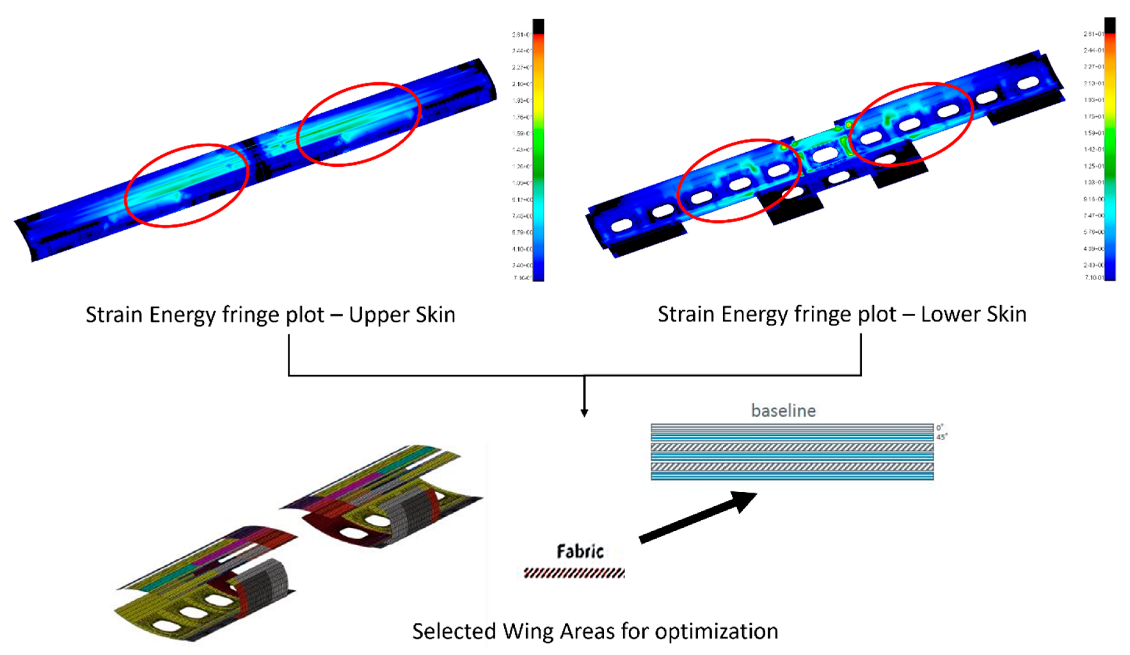
For what concerns the torsional modes, the selection of the areas of the wing to be tailored was less intuitive with respect to the flexural out-of-plane modes, thus increasing the importance of performing modal strain energy analysis to identify the most participating paths in the structure.
Figure 7 shows the results of the modal analysis, highlighting the area eligible for efficient improvement. By adding ±45° fabric layers over the entire wingspan on the inner mold line and outer mold line would not have been an optimized approach, as some areas of the wing structure do not contribute to the overall torsional stiffness.
The key elastic properties of the composite materials lie in those of the plies in laminates. More than 45° fabric layers are best suited to absorb the torsional energy rate, improving the torsional stiffness of the former layup. These zones were modified by adding ±45° fabric layers with respect to the baseline model in order to enhance the torsional mode frequencies. The different explored solutions are shown in
Table 3.
The results for the flexural and torsional modes are reported in [
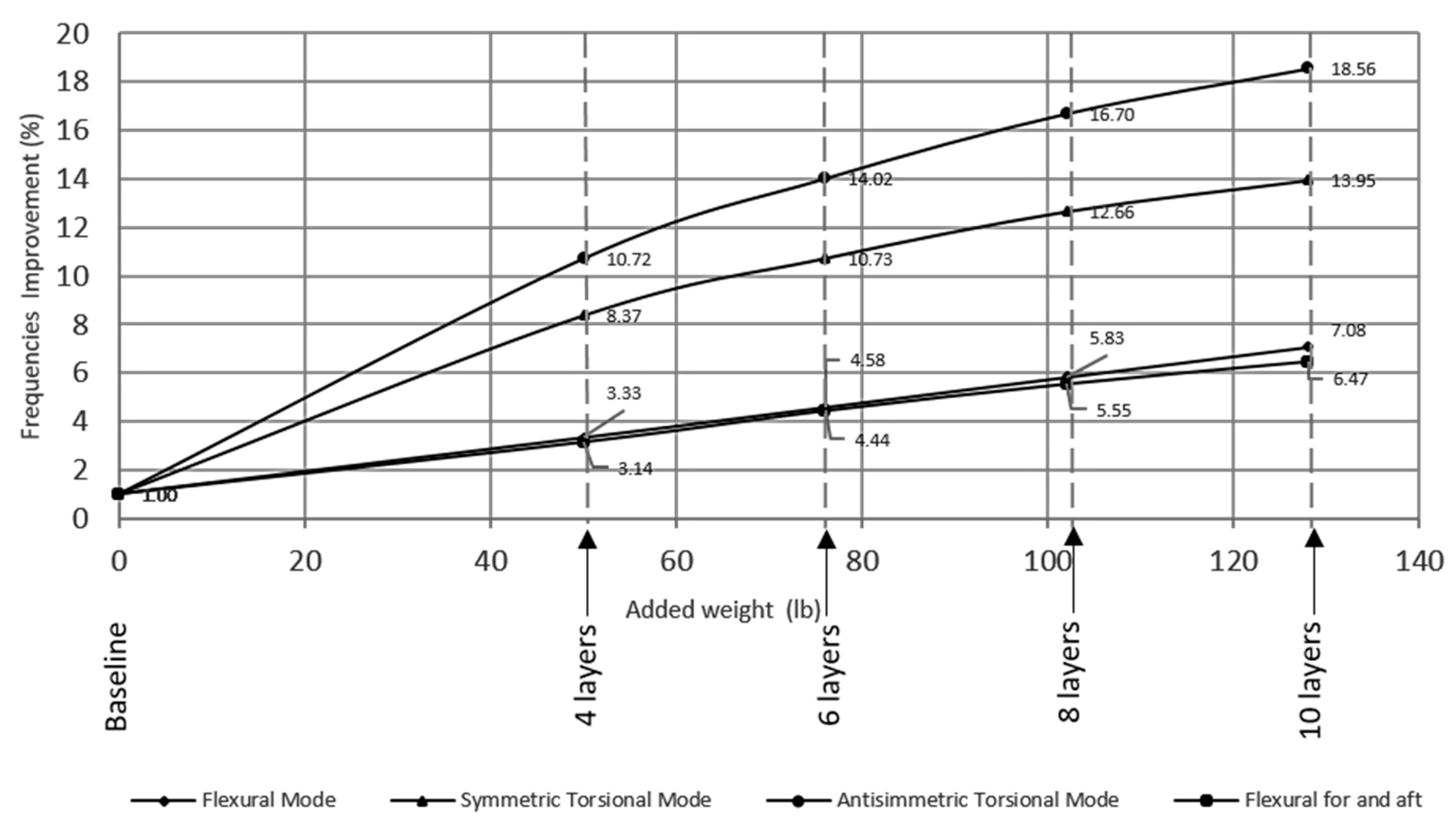
11], considering the baseline model as the starting point. Once again, it can be observed how improving the torsional modes did not have an effect of the same level as the flexural modes, although the percentage increase was higher with respect to what was shown in the previous paragraph (+7.1% in the flexural mode with respect to +1.9% in the torsional mode). This is explained by the fact that unidirectional layers placed in the wing’s spanwise direction are extremely effective for flexural stiffness while not really contributing to the torsional one; oppositely, ±45° fabric layers are effective for torsional stiffness and partially effective for the flexural one since, even if the direction of the fibers was not spanwise, the thickness of the wing box increased. As an additional result, during the procedure of adding plies to achieve a certain stiffness value, a plateau effect was observed. This is explained by the fact that the wing’s structure is not the only element contributing to the frequency placement of the fundamental aircraft modes. Airplane mode flexural and torsional frequencies vs. added mass are shown on
Figure 8.
3.3. Combined Flexural and Torsional Modes Tailoring
For the minimum frequency requirement of the elastic modes and the whirl flutter aeroelastic stability achievement, a combined tailored approach was explored aimed at further optimizing the final composite wing configuration.
The effects of the flexural and torsional mode frequencies were maintained also when the structural modifications were introduced as combined. This led to the consideration of a new model, obtained by coupling the effects linked to the hybrid stringers and pad model in addition to the ones deriving from adding ±45° fabric layers. Wing Dynamic Status: Helicopter and Aircraft Modes for Hybrid stringers and Pad + 2 Added ±45° fabric layers Model are shown in
Table 4.
The last configuration led to a total increment in the wing’s structural mass of 2.73%. It was deemed the best compromise able to satisfy all the structural dynamics and aeroelastic stability requirements, with an acceptable weight penalty and a non-negligible advantage of ease of manufacturing.


 ,
, 


