Article

Application of Aeroelastic Tailoring for Load Alleviation on a Flying Demonstrator Wing †

by
Wolf R. Krüger
1,*,
Yasser M. Meddaikar
1,
Johannes K. S. Dillinger
1,
Jurij Sodja
2 and
Roeland De Breuker
2
1
German Aerospace Center (DLR), Institute of Aeroelasticity, 37073 Göttingen, Germany
2
Aerospace Structures and Computational Mechanics, Delft University of Technology, 2628 CN Delft, The Netherlands
*
Author to whom correspondence should be addressed.
This article is an extended version of the paper published at the Deutscher Luft- und Raumfahrtkongress (DLRK), Friedrichshafen, Germany, 4–6 September 2018.
Aerospace 2022, 9(10), 535; https://doi.org/10.3390/aerospace9100535
Submission received: 25 July 2022 / Revised: 1 September 2022 / Accepted: 14 September 2022 / Published: 21 September 2022
(This article belongs to the Special Issue Smart Wing Aircraft)

Abstract

:
This article presents the application of aeroelastic tailoring in the design of wings for a flying demonstrator, as well as the validation of the design methodology with flight test results. The investigations were performed in the FLEXOP project (Flutter Free Flight Envelope Expansion for Economical Performance Improvement), funded under the Horizon 2020 framework. This project aimed at the validation of methods and tools for active flutter control, as well as at the demonstration of the potential of passive load alleviation through composite tailoring. The technologies were to be demonstrated by the design, manufacturing and flight testing of an unmanned aerial vehicle of approximately 7 m wingspan. This article addresses the work towards the load alleviation goals. The design of the primary load-carrying wing-box in this task is performed using a joint DLR–TU Delft optimization strategy. Two sets of wings are designed in order to demonstrate the potential benefits of aeroelastic tailoring—first, a reference wing in which the laminates of the wing-box members are restricted to balanced and symmetric laminates; second, a tailored wing in which the laminates are allowed to be unbalanced, hence allowing for the shear–extension and bending–torsion couplings essential for aeroelastic tailoring. Both designs are numerically optimized, then manufactured and extensively tested to validate and improve the simulation models corresponding to the wing designs. Flight tests are performed, the results of which form the basis for the validation of the applied aeroelastic tailoring approach presented in the article.

1. Introduction

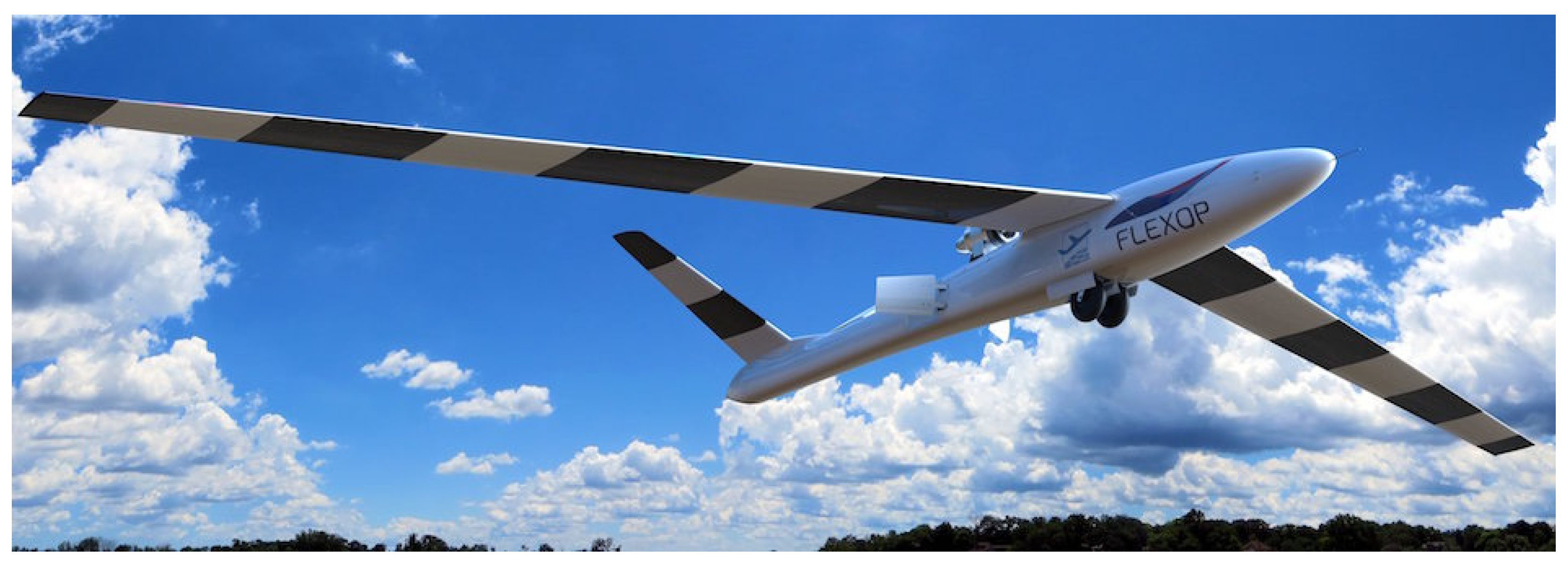
1.1. The FLEXOP Project

The Flutter Free Flight Envelope Expansion for Economical Performance Improvement, or FLEXOP [1], was a European research project running from 2016 to 2019, aiming at developing and demonstrating technological concepts to improve the performance of flexible, high-aspect ratio, swept aircraft wings. Two aspects were addressed in the project—first, load alleviation techniques through aeroelastic tailoring and, second, active flutter control were to be demonstrated in flight, using an unmanned aerial vehicle (UAV) as the platform [2,3] (see Figure 1). The approaches which were developed have then been applied to the design of a full-scale transport aircraft in a numerical scale-up task.
For the FLEXOP UAV, three different wing pairs were designed, manufactured and tested. The first wing pair was a conventionally designed reference configuration, while the second wing pair demonstrated the application of aeroelastic tailoring [4,5] for load reduction. These two configurations are described in this article. A third wing pair [6] was designed to flutter within the operational envelope of the aircraft and was intended to demonstrate active flutter suppression.
The design cycle of two FLEXOP wing types is presented in this article. The first pair of wings is designed using conventional balanced-symmetric laminates, thus denoted as “reference” throughout the following article. The second pair of wings also allows for unbalanced laminates, thus allowing for a much larger design space and exploitation of composite coupling benefits; this wing will be denoted in the following as “tailored”. The wing structures were optimized using an aeroelastic tailoring toolchain, developed at the Delft University of Technology (TUD) and the DLR Institute of Aeroelasticity (DLR). The wings were then manufactured based on the outcome of the optimization task. Static tests were performed to characterize the stiffness behaviour of the actual manufactured wings. An airworthiness test was then performed, where the wings were subjected to the design limit loads. Subsequently, a ground vibration test (GVT) was performed to obtain the dynamic response of the aircraft. Those ground tests were used for a final update of the finite element models. Finally, flight tests were performed with the UAV where a set of load-relevant manoeuvres were flown, forming the basis for the comparison of predicted and current behaviour of both sets of wings presented in this article.

1.2. Aeroelastic Tailoring for Load Alleviation

The use of composite materials in aircraft structures offers several advantages over conventional metals. Among others, the directional nature of composite stiffness can be optimized such that aeroelastic effects are exploited to achieve, for example, passive load alleviation. This interactive subject involving composite optimization considering or targeting aeroelastic effects is known as aeroelastic tailoring. Aeroelastic tailoring has been studied extensively in the past for a great number of applications. Starnes Jr et al. [7] applied an approximation-based optimization to minimize the weight of a wing structure subjected to different combinations of buckling, strength, displacement and twist constraints. Hollowell et al. [8] demonstrated the considerable effects induced by the coupling terms in the bending stiffness matrix by analysing the effect of bending–twist coupling on the aeroelastic behaviour of composites’ plates with various symmetric, unbalanced stacking sequences. A valuable survey on aeroelastic tailoring effects as a result of the directional stiffness in orthotropic composites was provided in Shirk et al. [9]. The authors investigated the possible influence of rotated fibre angles on minimum weight, twist, normal modes, flutter and aerodynamic performance for various configurations, ranging from fighter aircraft to forward-swept configurations. A general overview on optimization technologies covering optimizations on the panel level to the aeroelastic optimization of composites in aircraft wings was provided in Vanderplaats et al. [10]. Eastep et al. [11] study the influence of layup orientation in a straight fibre design on the optimized wing mass, subject to constraints on strength and roll-reversal velocity. Guo et al. [12] demonstrate the potential of aeroelastic tailoring in increasing the flutter speed by optimizing for the fibre orientations of a composite wing box. In a more recent work, Leon et al. [13] maximized the flutter eigenfrequency of a composite plate wing with ply angles as design variables, considering symmetric and non-symmetric laminates.
Aeroelastic tailoring studies based on lamination parameters have also been studied extensively. Kameyama et al. [14] used a composite plate wing to demonstrate the influence of lamination parameters on the flutter and divergence characteristics. The minimization of compliance of a variable-stiffness slender wing represented as a beam was demonstrated in Abdalla et al. [15]. The cross-sectional properties of the beam were parametrized using lamination parameters that defined the membrane stiffnesses of the box cross section. The results show that variable stiffness layups can significantly outperform structures comprising constant stiffness. Unbalanced laminates in particular, comprising bending–torsion coupling, lead to the best performance in terms of compliance. A two-level optimization strategy was proposed by Liu [16]. Allowing for symmetric and unbalanced laminates, a lamination parameter-based weight minimization was performed before applying genetic algorithms for the derivation of stacking sequences. The objective function in the second optimization step comprises a minimization of the square distance between optimal lamination parameters from the first step and lamination parameters corresponding to the genetic algorithm step. Dillinger [17,18] presented an optimization approach for composite aircraft wings based on lamination parameters. The introduction of that publication also presents an extensive overview over the development in the field. Next to those sources mentioned, the article by Livne [19] provided an extensive literature overview on load control and contained a section on aeroelastic tailoring.
Experimental studies in wind-tunnel experiments have also been presented in recent works. Meddaikar and Sodja described a set of experiments where aeroelastically tailored wings have been built to validate the design process and demonstrate the feasibility of high deflection models for wind tunnel experiments [20,21,22], first on an unswept wing, then on a forward swept wing. While these experiments were performed in low-speed wind tunnels, Dillinger et al. described a comparison of two tailored wings tested in the ONERA S2Ch wind tunnel at transonic flow speeds [23].
Applications of aeroelastic tailoring in optimizing an actual flying aircraft in the available literature are very limited. The HiMAT [24,25]—highly manoeuvrable aircraft technology demonstrator—was designed to achieve a desirable twist deformation through aeroelastic tailoring in flight tests, such that a compromise in drag performance during transonic manoeuvre and cruise could be achieved on a remotely piloted research vehicle. More recent work includes the T-wing project where aeroelastic tailoring was applied to a next-generation tiltrotor composite wing [26] in order to isolate and tune the wing bending and torsion frequencies to improve aeroelastic stability margins. The flight tests are planned for a next phase in the project.
The present work aims to further research in this area through flight tests aimed at demonstrating passive load alleviation, to optimize a composite wing structure for its weight, using an aeroelastic tailoring framework that includes various constraints, unconventional laminate types, and several load-cases, and to validate the actual benefits of such an optimization exercise on a flying demonstrator. Initial results from the optimization and ground tests were presented in [5], while the present paper consolidates them together with flight test results.

2. Aeroelastic Tailoring Framework

2.1. Overall Process

The aeroelastic tailoring approach applied in this work is a multi-fidelity approach, originally developed in the European Smart Fixed Wing Aircraft project and described in [27]. The process addresses the fact that the design space for the design of aeroelastically tailored wings is usually very large, due to the large number of design variables and constraints that are typically associated with this type of problem. A two-step approach is thus followed to systematically converge on an optimized structural design. In FLEXOP, a modified version of the process using a sequential approach of using beam and shell models for the wings is implemented, as shown in Figure 2.
Step 1 of the toolchain uses a stiffness optimization tool based on a beam model of the wing. In this step, initial design studies can be performed to explore the design space, in which the effects of different material types, laminate reference coordinate system definitions and wing-box layout can be studied. The optimized wing structural design obtained from this step serves as the starting point for design Step 2.
Step 2 employs a genetic algorithm (GA) for stacking sequence optimization, and uses a shell-based finite element model of a higher fidelity. The outcome of this step is the layup plan that is required for manufacturing.

2.2. Beam-Model-Based Stiffness Optimization

The first step in the optimization toolchain is performed using the design tool PROTEUS, developed at TUD. The tool is an aeroelastic wing design tool developed to improve the conceptual design of aircraft wings by considering aeroelastic effects. In this regard, the tool is computationally efficient to enable quick design optimization studies. A detailed explanation of the design tool is presented in [28]. In the design process, a 3D cross-sectional modeler [29] first compiles the wing cross-sectional properties into equivalent Timoshenko stiffness matrices. Second, a static aeroelastic analysis combines a geometrically non-linear Timoshenko beam model [30] based on the co-rotational formulation, to the steady vortex lattice method (VLM)-based aerodynamic model [31]. Finally, a linear dynamic aeroelastic analysis is based on a linearized stiffness matrix around the non-linear static equilibrium solution. This is then coupled to a mass matrix and an aerodynamic model based on the unsteady VLM [31].
For the composite optimization, the stiffness of the composite laminates is represented by so-called lamination parameters. These parameters describe the stiffness behaviour of a composite laminate by means of convenient continuous design variables. The lamination parameters together with the laminate thickness are the design variables in this step. Lamination parameters [32,33] present a very useful parametrization scheme for composite laminates and have been extensively applied in the past, with some of the early works presented in [32,33,34].
A detailed description of this step of the process, together with the results from the optimization studies, was presented in [4], and validation with FLEXOP test data in [35].

2.3. Shell-Model Based Stacking Sequence Optimization

The design obtained in the previous step represents an optimal stiffness distribution of the wing structure. This design is used as a starting point in this second optimization step. For this step, a genetic algorithm (GA) is applied, using a technique known as stacking sequence tables (SST) [36,37]. The GA with SST follows rules of generalized laminate blending [38] to ensure ply continuity between adjacent design fields and also provides information on ply-drop sequence. The GA also includes several industry-standard design guidelines related to laminate and ply-drop requirements. For the representation of static wing loads, an aeroelastic tailoring framework (see [27]) is utilized, which uses NASTRAN to generate the required optimization responses and sensitivities. Part of the process is a modelling strategy based on NASTRAN shell-element models of the wing, coupled with a doublet lattice model (DLM) for the aerodynamics. The aeroelastic model is then obtained through splining between the structural and aerodynamic models, using an in-house model generator, ModGen [39].
The numerical models of the FLEXOP wing, which are the output of the two-step process described above, are shown in Figure 3.

3. Wing Design and Structural Optimization

3.1. Planform and Design Specifications

The UAV wings follow a traditional wing box concept, comprising upper and lower skins, ribs and spars, and, given the slender wing layout, no stringers. The wings have a full span of approximately 7 m, an aspect ratio of 16.33, a leading-edge sweep angle of 20° and a custom asymmetric airfoil. The key design specifications of the wing are listed in Table 1. For the structural design, a carbon fibre/epoxy material with the technical specification Hexcel 8552/34%/UD134/AS4Tape is used.

3.2. Optimization Specifications

The objective of the design optimization is to minimize the structural mass of the wing. For a sufficiently large design space, the wing is split into 12 spanwise design regions, as shown in Figure 4. Considering ease of manufacturability, only one chord-wise design region is applied. Each design region corresponds to an area of the wing having the same laminate, or effectively the same stiffness. The stacking sequences in the upper and lower skins and front and rear spars are optimized for, while the laminates in the ribs are pre-defined. Additionally, the leading edge, trailing edge and flaps are not a part of the optimization exercise.
All three wing designs in FLEXOP are very different from their flexibility distribution, and it is thus difficult to compare the performance of these designs. To ensure that all wings perform aerodynamically similarly at cruise speed, a constraint on the 1 g cruise shape is placed in the optimization. This certifies that the benefits obtained by means of aeroelastic tailoring do not come at the expense of aerodynamic performance. At the 1 g cruise point, the twist distribution varies linearly between 0° at the root and −2° at the tip.
The outputs of the optimizations are the blended stacking sequence as well as the jig-twist. The physical constraints used in the optimization include laminate strength, buckling, the tip-twist at 1 g cruise, a static divergence constraint and an aileron effectiveness constraint, requiring an effectiveness of more than 15% in all conditions. For the laminate constraints, a 10% rule is applied. All wings use a symmetry and ply contiguity (max. 4) constraint. The outer plies have to obtain a ±45° direction, and the outer maximum disorientation is set to 45°. The reference wing is constrained to balanced laminates, and the tailored design makes use of unbalanced laminates. As sizing load cases, two manoeuvres, one at 45 m/s (TAS) and one at −2 g at 45 m/s (TAS), were selected.

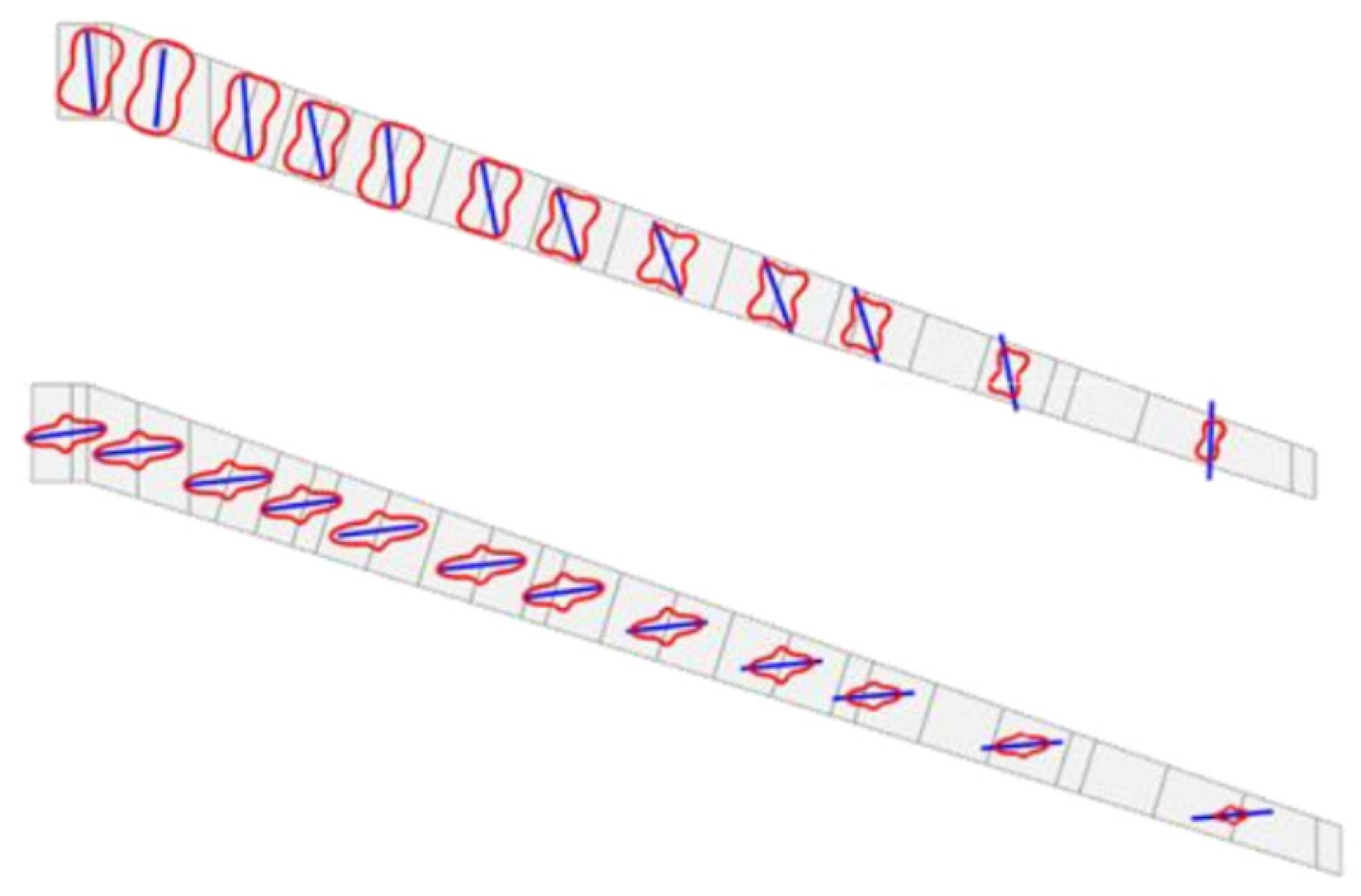
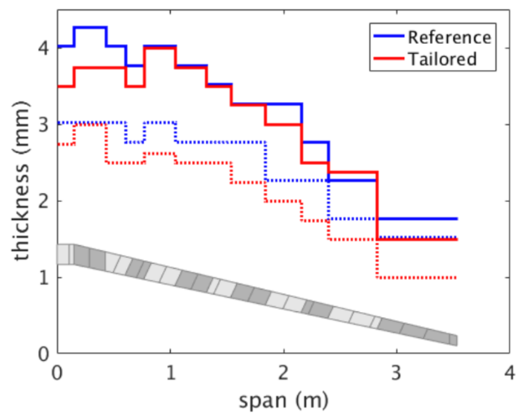
3.3. Optimization Results

In order to provide a comparable basis for the aeroelastic tailoring demonstration, two wings are designed using the aeroelastic tailoring framework described in the previous sections. The reference wing is designed with balanced-symmetric-type laminates, while the tailored wing is restricted only to symmetric laminates. The tailored wing thus has a larger design space. Therefore, it should be able to better exploit the bending–torsion capabilities of anisotropic composites to design more efficient wings.
In Table 2, the optimization results of the different wings and optimization steps are compared. The results obtained from the first optimization step using PROTEUS (“stiffness optimization”) were detailed in [4]. Along with the optimal stiffness design of the wing, this first step also provides the optimal jig-twist. This jig-twist is then utilized directly in the stacking sequence optimization.
The results from the second (“stacking sequence”) optimization step are the focus of the following discussion. First, it can be seen that stiffness-optimal designs obtained from the first optimization step in both the reference and tailored wings are between 12 and 17% lighter than their stacking sequence counterparts. This increase in mass can be expected since the stacking sequence design is constrained by the discrete steps of ply angles and thickness. Additionally, the stacking sequence design includes the constraint of laminate blending and additional laminate guidelines. The increase in mass in the stacking sequence design can be attributed to these reasons, which are not accounted for in the stiffness optimization step.
Second, the final stacking sequence design of the tailored wing results in a structural mass of 6.30 kg per wing half, in comparison to the 6.88 kg achieved for the final stacking sequence design of the reference wing. This weight saving of close to 8% arises purely out of the enlarged design space on account of the unbalanced laminates, which then leads to a better use of composite anisotropic properties. This behaviour results in the shown root bending moments, which for the reference wings are reduced by 3% (5 g) and 6% (−2 g) for the tailored wing when compared to the reference wing. Note that the loads are almost identical for the 1 g case, as this was a design assumption.
The comparatively better performance of the tailored wing is a direct result of the enlarged design space offered by unbalanced laminates. This larger design space is visualized in Figure 5, which shows the polar distribution of the A11 term of the in-plane stiffness matrix in the upper skins of the reference and tailored wings. The highly anisotropic stiffness distribution in the tailored wing results in the classic bend–twist composite coupling that produces a nose-down twist upon upward bending.
Consequently, a pull-up manoeuvre, for instance, produces a nose-down twist, which in turn results in an inboard-shifting of loads and, finally, in an alleviated root bending moment, as listed in Table 2. The reduced loads result in lesser thickness requirements, as shown in Figure 6, leading to the savings in structural weight. The thickness distribution shows two expected trends: (1) the tailored wing requires a lower thickness in the skins compared to the reference wing, on account of the reduced loads, (2) the thickness in the upper skin is larger than in the lower skin for both the tailored and reference wings, given the larger load factor for the sizing pull-up manoeuvre, i.e. +5 g against the push-down manoeuvre −2 g, causing the upper skin to experience larger compressive loads than the lower skin; thereby requiring larger thickness to meet buckling constraints, as well as strength constraints given the lower strength allowables in compression.
The lift redistribution towards the inboard section of the wing in the tailored design is visible in Figure 7, which shows the spanwise lift distribution of the wing for different manoeuvre loads.
The corresponding structural twist of the respective wings is shown in Figure 8. A large negative structural twist angle at the tip of the wing implies a nose-down twist, which is beneficial in a pull-up manoeuvre to alleviate loads. This negative structural twist in the case of the 5 g manoeuvre load is significantly larger in the tailored wing, which in turn helps in shifting the loads inboard.
The optimized designs obtained from this step are used to generate full aircraft aeroelastic models using design data available for the fuselage and empennage. These models are subsequently used to perform aeroelastic analyses and to generate various models required for controller synthesis.

3.4. Manufacturing of Wings

The reference and the tailored wing were built using carbon fibre-reinforced plastic (CFRP) material at FACC (Austria), a partner participating in the project. The layup of the CFRP material comprising the wing skins and the spars, a standard aerospace-grade carbon fibre unidirectional prepreg material designated AS4-8552, is based on the optimisation results presented above.

4. Ground Tests

4.1. Shape and Load Sensing Methodology

To enable in-flight wing shape and load measurements, a temperature and strain sensing system based on fibre Bragg grating (FBG) sensors was integrated into both the reference and tailored wing. The strain sensing system consists of 20 rosettes with FBGs oriented at 0°, 45°, and 90°. The rosettes were installed on both the top and bottom wing skins along the span, for a total of 120 strain sensors. The layout is depicted in the schematic seen in Figure 9. Due to hardware malfunctions, the temperature sensors were not operational during the test flights and are therefore not considered in the subsequent analysis.
The measured strain values are used for the calculation of the internal loads such as bending moment and shear force, pertinent vertical deflection, and torsional twist. The developed method draws upon the Euler–Bernoulli beam theory and the work of Skopinski et al. [40] to set up a data-based framework for the calculation of the necessary load and shape-sensing parameters based on the strain distribution along the wing span. Using this approach, the required loads and pertinent deflections can be reconstructed [41].
The sensing parameters were calculated using the static test load cases (bending, torsion) and resulting FBG strain distributions as calibration data. The load sensing parameters were found exclusively based on experimental data, requiring only one bending and one torsion case. On the other hand, an extensive set of load cases was needed to establish all the required shape-sensing parameters. Due to the limited number of experimental load cases, a calibrated NASTRAN finite element model of the two wings was used to generate a sufficient dataset of equivalent simulation strains to calculate the required shape sensing mapping parameters. The mapping parameters were then calculated by relating the simulation strains to the FBG data, thereby enabling the experimental calculation of the wing shapes [41].

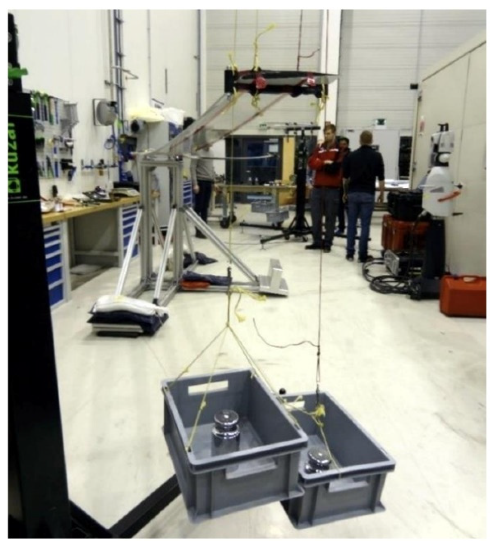
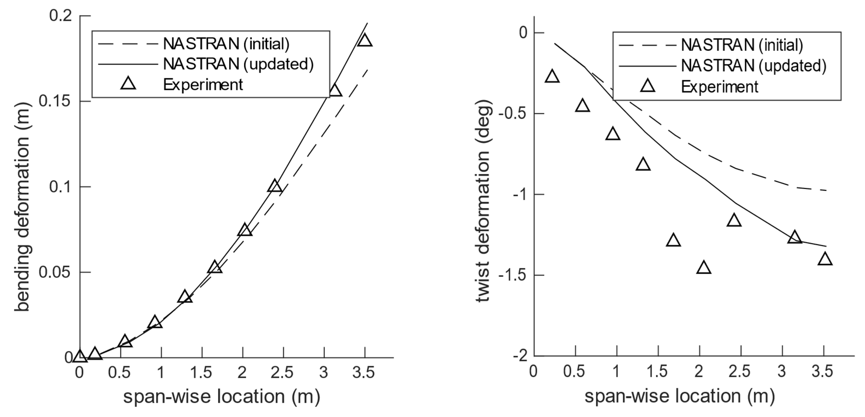
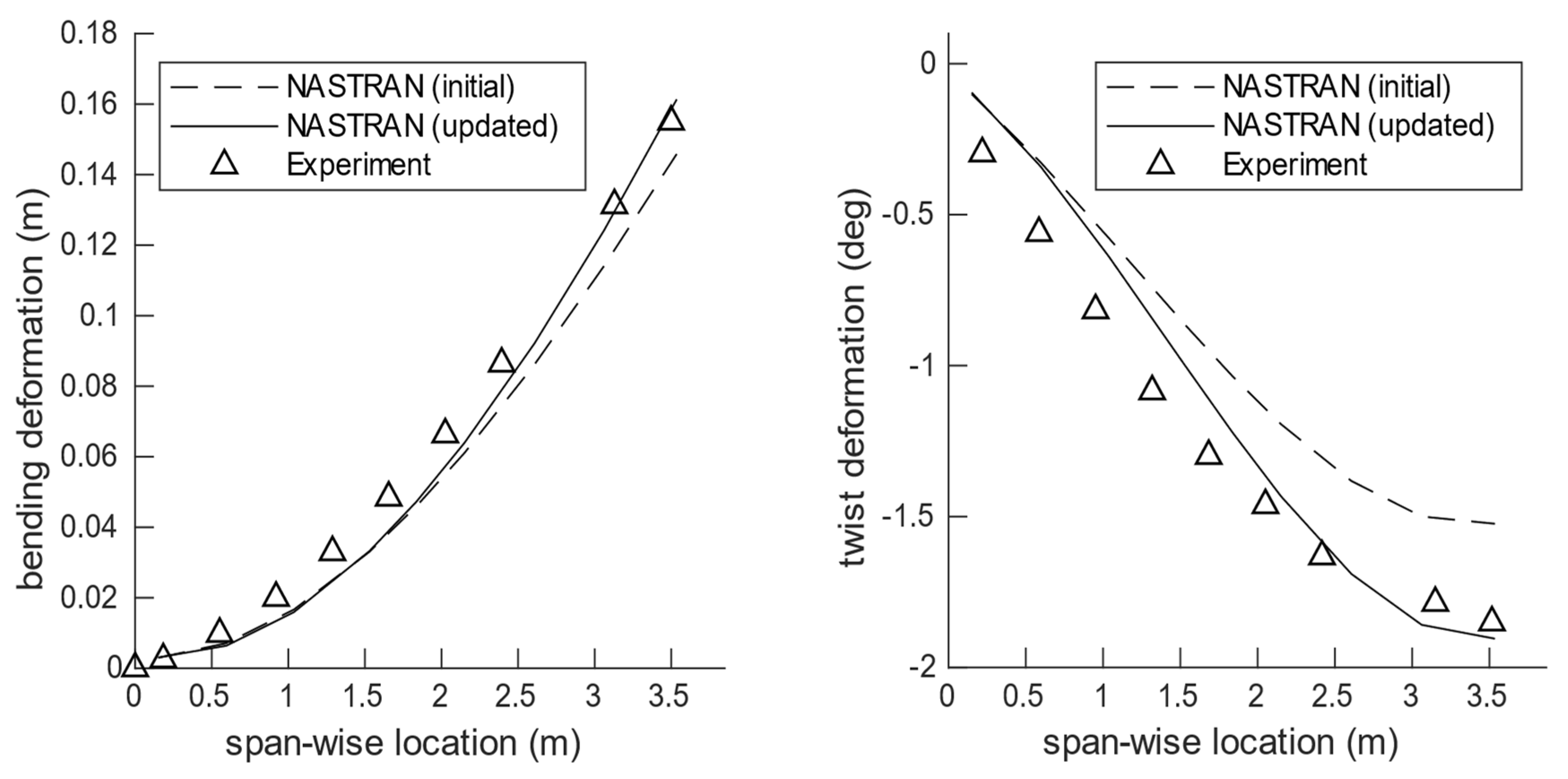
4.2. Static Test and Model Update

The main objective of the static test was the assessment of the stiffness properties of the manufactured wings and validation of the pertinent structural models developed and utilized in its design process. A pair of the manufactured wings was mounted in a dedicated test stand, with a similar attachment mechanism as in the wing-fuselage connection. In order to achieve representative boundary conditions at the root of the wing, both the port and starboard halves of the wings were mounted in the test stand and connected in the middle. Accordingly, the full aircraft structural FE model was used in the update process with an appropriate boundary condition to account for the static fixture. Prescribed shear and torsional loads were applied to both halves in a symmetric fashion as illustrated in Figure 10. A laser-tracking-based system was used to measure the position of pre-placed markers on the wing, from which the displacements and torsional rotation were calculated.
Discrete loads were applied by hanging weights at the wingtip. Both positive and negative shear loads were applied by flipping the wing from an upside-up to an upside-down orientation. A torque bar was mounted on top of the load clamp for torsional load cases in order to be able to apply a sufficient amount of torque by increasing the lever arm. To avoid accidentally damaging the wing structure during the test, a set of maximum shear and torque loads was pre-determined. Load clamps fitted to the wing shape were used to spread the load gradually into the wing structure to avoid causing any structural damage due to local concentrated loads. In addition to the shear and torsion load cases, three load-sets were also tested corresponding to equivalent flight loads at +5 g, +2.5 g and −2 g loads using sandbags. These serve as test cases to compare the initial and final updated FE models, where the model-updating process uses only the simplified shear and torsion load cases.
The bending and torsional displacement corresponding to the tested +2.5 g equivalent flight loads is shown in Figure 11 for the reference wing. A comparison between the initial NASTRAN FE model and the experimental results is also shown in the same figure. The initial FE model corresponds to the optimized design obtained in the second optimisation step as described earlier. It is seen that a maximum deviation of close to ~10% is observed in the tip displacement between the initial FE model and the physical structure. This difference can be attributed to a mix of reasons—modelling assumptions and simplifications, manufacturing deviations, material scatter, experimental accuracy, etc.
A first attempt at updating the stiffness model was performed by introducing a knock-down on the engineering stiffness terms (E1; E2; G12) in the FE model of the wing and in the clamp used for the wing attachment. For the wing, the stiffness terms in the upper and lower skin were used for the update using a similar discretization as in the design region definition shown in Figure 4. The objective to be minimized in the optimization problem was a function of the difference between experimental and simulated displacements. A weighted sum of the contributions from the bending and torsional displacement components was used. With this relatively simple first approach to updating the stiffness of the wing, an agreeable match for the bending displacement is seen in the updated FE model shown in Figure 11. The twist displacement, however, improved in the updated model, still shows some discrepancy when compared to the experimental measurements which can be attributed to two main reasons. First, the small magnitude of twist measured under the loads make the twist measurement very susceptible to noise, as seen at the markers near the mid-span, on account of the accuracy of the measurement system and experimental process itself. Second, a near constant offset between the model and the experiment is seen, indicating some form of non-linearity in the attachment, such as a free-play, which is not modelled. This remains to be investigated further. Nevertheless, the stiffness characterization of the wing structure obtained from this static update is judged to be acceptable to be used for further analyses.
A similar exercise was also performed for the tailored wing, and the results from the model updating are shown in Figure 12.

4.3. Airworthiness Test

In addition to the static tests, an airworthiness test was performed on the wings in order to confirm that they can sustain the design limit loads, namely 5 g pull-up and −2 g push-down manoeuvres at the design conditions. A picture of the test-stand with the reference wing mounted is shown in its unloaded and loaded state in Figure 13. The wing was loaded with a 5 g and −2 g equivalent load by hanging sandbags at six span-wise locations on either side of the wings. In the case of the −2 g loads, the wing was flipped over before applying the loads. The equivalent loads were derived by matching the deflected shape of the reference wing with that of the FE model subjected to the limit loads. By applying the loads in this way, the resulting shear force and the bending moment along the span were recovered, as shown in Figure 14. One can observe that the equivalent shear force changes in discrete steps due to the fact that the forces are applied at discrete locations along the span of the wing. Nevertheless, the equivalent bending moment follows the bending moment in flight very faithfully.
The airworthiness tests showed that the wings can sustain the limit loads without any detectable structural damage, and were therefore deemed safe to operate.

4.4. Ground Vibration Tests

Following the update of the stiffness properties of the numerical models using the static test results, a ground vibration test (GVT) was performed to characterize the dynamic behaviour of the manufactured wings, and also of the complete aircraft (see Figure 15). In the case of the GVT, the full UAV was instrumented with accelerometers, suspended on elastic strings and excited with an impulse hammer. From the time-response of the accelerometers, a modal analysis was performed to obtain the eigen frequencies, mode shapes and damping corresponding to each of the modes. The results were used to update the aeroservoelastic models of the full UAV aircraft, which are critical for the final controller designs in the next phase. In addition, the GVT campaign was used to test the complete sensor and data acquisition setup of the aircraft. Details of the ground tests of the FLEXOP aircraft can be found in [41].
A comparison of the modal characteristics between the GVT experimental and a modal analysis performed on the FE model updated from the static test results is presented in Table 3. It is seen that the FE model already captures the out-of-plane bending behaviour of the wing well. On the other hand, the in-plane behaviour of the wing and the stiffness and mass modelling of the fuselage and empennage need to be investigated in more detail. Thus, in the next step, an update of the aircraft FE model was made simultaneously, considering results from the static tests and GVTs.

5. Flight Test

5.1. Flight Test Approach

The flight tests with the FLEXOP UAV took place at Special Airport Oberpfaffenhofen, Germany. Due to German law, they had to be performed within visual line of sight in a controlled airspace. The flight path has a horse-race pattern, as shown in Figure 16.
The manoeuvre loads for the aeroelastic tailoring demonstration were introduced during coordinated turns and push-up-push-over manoeuvres during the straight leg. The FBGs on board recorded the in-flight strains. The measured strains along with dedicated shape sensors were used to calculate deformations (displacement and twist), sectional loads and the wing root bending moment. The difference in the root bending moments, the sectional loads and the bending–torsion coupling-induced twist during the introduced manoeuvres between the reference and tailored wing designs are crucial measures in evaluating the aeroelastic tailoring capability of the applied framework. Additionally, an update of the aeroelastic models was also based on these measurements.
The flight test campaign itself was divided into four phases [42]. The first and second phases of the flight test campaign dealt with gathering data with the reference wing. For the third phase, the tailored wing was mounted for load alleviation testing. Unfortunately, phase 4, with the specially designed flexible wing dedicated to the demonstration of controller-based flutter suppression, was not able to be conducted in the scope of the FLEXOP project due to time constraints.
Five test flights for phase one and two with the reference wing were conducted. Static aeroelastic testing manoeuvres, aircraft dynamic performance identification manoeuvres, as well as autopilot functionality (baseline controller) checks were all performed at least once. All of the aircraft systems were tested and performed as expected. During the final flight, phase 3, using the tailored wing, data from 22 min of flight time were gathered and good-quality data regarding aeroelastic manoeuvres were acquired.
Two flight manoeuvres, a sustained turn at a constant bank angle and a pull-up-push-over manoeuvre were selected to be executed during the flight-testing campaign in order to demonstrate the passive load alleviation mechanism due to aeroelastic tailoring and to perform the validation of the aeroelastic tailoring toolchain developed by TU Delft and DLR—see Section 2 above.
The sustained turn at a constant bank angle was chosen for two reasons. First, the aircraft had to be flown in line of sight within a certain flight perimeter and altitude. With these limitations in mind, the sustained turn could be performed at a constant velocity for as long as necessary to collect enough data for subsequent analysis. Second, the load factor during such a manoeuvre strongly depends on the bank angle of the turn. Therefore, various load factors can easily be tested by simply adjusting the bank angle of the turn.
A closer description of the flight test programme and a number of selected measurement results can be found in [42].

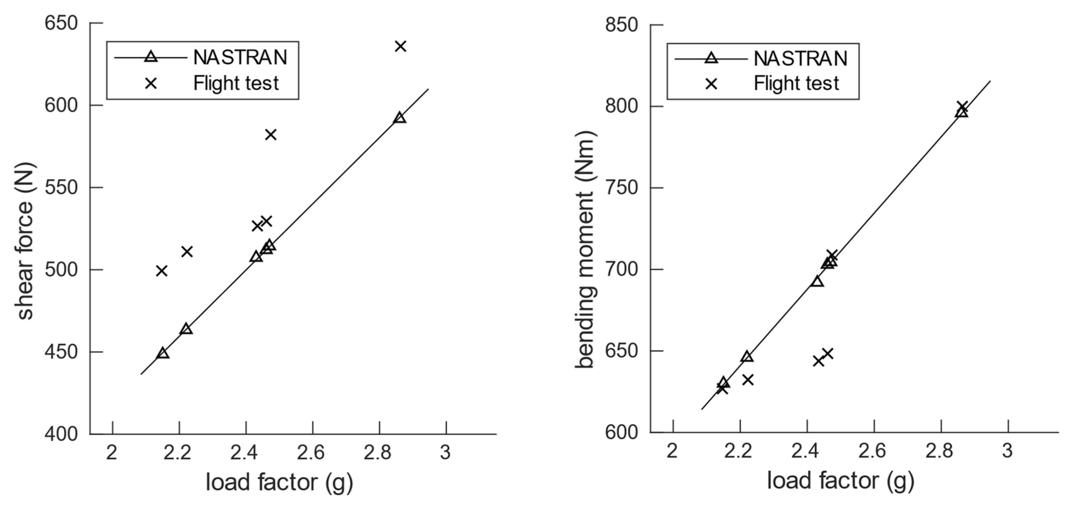
5.2. Comparison between Flight Test Results and Simulation Models

As stated above, two major goals were targeted in the flight test campaign: first, a validation of the aeroelastic tailoring process of TU Delft and DLR by comparing simulation results to flight test results; second, a validation of the load reduction potential in the aeroelastic tailored wing when compared to the classic design of the reference wing.
In the following paragraphs, the simulation results for the DLR wing model, i.e., the finite element model, will be compared to the test flight results, both for the reference wing and for the tailored wing. The results from a comparable exercise for the TU Delft beam model are discussed in [35].
Table 4 lists the static manoeuvres that were tested during various test flights. The load factors were corrected to account for a variation in flight mass due to differing fuel levels. Additionally, only flight manoeuvres where the load factors remain relatively steady for a useable period of time were chosen. Details on the reconstruction of flight shape and loads, including corrections for temperature and drift from the FBG system is presented in [41].
A comparison of the aeroelastic response between the flight tests and simulations using NASTRAN is summarized in Figure 17 and Figure 18 for the reference wings as well as in Figure 19 and Figure 20 for the tailored wings. The simulations are carried out using the updated FE model discussed earlier in Section 4.3.
With regard to the bending deformation, a good agreement between the flight test results and the aeroelastic simulations is observed, with a maximum difference of ~7% and ~8% for the reference and tailored wings, respectively, at the wingtip. The difference in the twist at the tip, however, does not show as good a match. The maximum difference in this case is ~30% for both the reference and tailored wings. This can be attributed to the fact that structural twist in itself is relatively small and any error from the strain measurements from the FBGs is more visible in the reconstructed twist. Moreover, as discussed earlier in the stiffness update using static test (Figure 11 and Figure 12), while the updated models showed good match with the experimental results for bending displacement, the match in the twist deformation was relatively poor.
Flight loads are compared in terms of shear force and bending moment at the wing root. In the case of the reference wings, the difference between the flight test loads and aeroelastic simulations are ~14% and ~6% for the root shear force and bending moment, respectively, and similarly ~12% and ~9% in the case of the tailored wings. In the NASTRAN simulations, a perfect linear relationship is expected between the deformation or loads and the load factor. However, a small deviation in the simulated points is observed with respect to a fitted line. This is a result of different manoeuvres being performed at slightly different velocities, as shown in Table 4.
The wing loads for the reference and tailored wings are aggregated in Figure 21, where the root bending moment and shear force are plotted for different flight manoeuvre points. The shear force at the root effectively represents the amount of load the wing carries. When neglecting the loads on the tail plane and fuselage, this shear force should amount to the weight of the fuselage suspended between the wings.
For a given shear force at the root, it is found that the tailored wing exhibits a lower root bending moment when compared to the reference wing. This is a result of the tailored wing shifting the loads more effectively inboard, reducing the bending moment and thus potentially being able to reduce structural weight. Ideally, the trend lines for the two wings would converge at a point which would correspond to a 1 g flight manoeuvre at the design mass of 65 kg. This is a result of the design requirement wherein both wings have the same flight shape at 1 g cruise. At load levels above this, the tailored wing would have a lower slope between the root bending moment and shear force. However, the opposite is observed when constructing a linear fit through the measured flight data. This is largely attributed to the scatter in flight measurement, observed more prominently in the case of the reference wing. Based on a small number of points, the linear regression is influenced heavily by the data scatter. It is, however, clear that for a given shear force or load carried by the wing, the bending moment at the root is lower for the tailored wing when compared to the reference, thereby demonstrating the passive load alleviation on account of aeroelastic tailoring in the tailored wing.
From the above results, it can be seen that a generally good agreement is observed between the flight test results and the simulations for both deformation and loads, with the exception of the twist deformation. An improvement in this comparison can be expected when the FE models of the wing are further updated, for instance to better characterize their torsional behaviour. At the same time, there is also uncertainty when considering the flight test data given the accuracy of the various measurement systems. This can be observed, for instance, from the flight test data where even for flight points with similar load factors, the deformation and loads are, at times, scattered.

6. Conclusions and Outlook

In the project FLEXOP, a joint DLR–TU Delft aeroelastic tailoring framework has been applied in the design of two pairs of wings. The goal of the activities was the demonstration of the benefits of aeroelastic tailoring for load alleviation, as well as of the design framework, on an actual flying testbench. For this purpose, the partners undertook a complete cycle of design, optimization, manufacturing and testing of an unmanned aircraft.
To be able to compare design principles, a reference wing has been designed using conventional balanced-symmetric laminates, while, in parallel, a tailored wing has been designed using symmetric laminates, thus allowing for better use of the beneficial bending-torsion coupling of composite laminates. The wing-box comprising upper and lower skins and front and rear spars has been optimized and the optimization results show a weight saving potential of ~8% when comparing the tailored design with the reference design.
The wings were manufactured using CFRP prepregs cured in an autoclave and were instrumented with various systems, including FBGs to measure strains and, through them, to extract deformation and loads. An extensive ground test campaign was performed including static tests for stiffness updating and a ground vibration test to update the aeroservoelastic model.
Flight tests have been conducted using both the reference and tailored wing performing various static flight manoeuvres. The results from the flight tests have been used to validate the DLR–TU Delft aeroelastic tailoring toolchain as well as to demonstrate passive load alleviation on a flying test bench.

Author Contributions

Conceptualization, W.R.K., Y.M.M., J.K.S.D., J.S. and R.D.B.; methodology and investigation, Y.M.M., J.K.S.D. and J.S.; writing—original draft preparation, W.R.K., Y.M.M., J.K.S.D., J.S. and R.D.B.; writing—review and editing, Y.M.M. and W.R.K.; funding acquisition, W.R.K. and R.D.B. All authors have read and agreed to the published version of the manuscript.

Funding

The work presented herein has been partially funded by the European Community’s Horizon 2020 Programme (H2020) under the Grant Agreement 636307. The FLEXOP project (Flutter Free FLight Envelope eXpansion for ecOnomical Performance improvement) is a project funded under the topic MG-1.1-2014, involving 10 partners.

Acknowledgments

The authors would like to acknowledge and thank the various partners—FACC, TU Munich, SZTAKI, AGI Germany and INASCO—for manufacturing and instrumentation of the wings, for the flight tests and for their support in performing the ground tests.

Conflicts of Interest

The authors declare no conflict of interest.

References

  1. FLEXOP Consortium. The FLEXOP Project. 2013. Available online: https://flexop.eu/ (accessed on 24 January 2022).
  2. Stahl, P.; Sendner, F.-M.; Hermanutz, A.; Rößler, C.; Hornung, M. Mission and Aircraft Design of FLEXOP Unmanned Flying Demonstrator to Test Flutter Suppression within Visual Line of Sight. In Proceedings of the 17th AIAA Aviation Technology, Integration, and Operations Conference, Denver, CO, USA, 5–9 June 2017. [Google Scholar] [CrossRef]
  3. Meddaikar, Y.M.; Dillinger, J.; Klimmek, T.; Krueger, W.; Wuestenhagen, M.; Kier, T.M.; Hermanutz, A.; Hornung, M.; Rozov, V.; Breitsamter, C.; et al. Aircraft Aeroservoelastic Modelling of the FLEXOP Unmanned Flying Demonstrator. In Proceedings of the AIAA Scitech 2019 Forum, San Diego, CA, USA, 7–11 January 2019. [Google Scholar] [CrossRef]
  4. Sodja, J.; Werter, N.; De Breuker, R. Design of a flying demonstrator wing for manoeuvre load alleviation with cruise shape constraint. In Proceedings of the AIAA/ASCE/AHS/ASC Structures, Structural Dynamics, and Materials Conference, Kissimmee, FL, USA, 8–12 January 2018. [Google Scholar] [CrossRef]
  5. Meddaikar, M.Y.; Dillinger, J.; Sodja, J.; De Breuker, R. FLEXOP—Application of Aeroelastic Tailoring to a Flying Demonstrator Wing. In Proceedings of the Deutscher Luft- und Raumfahrtkongress, Friedrichshafen, Germany, 4–6 September 2018. [Google Scholar]
  6. Rozov, V.; Hermanutz, A.; Breitsamter, C.; Hornung, M. Aeroelastic Analysis of a Flutter Demonstrator with a very Flexible High-Aspect-Ratio Swept Wing. In Proceedings of the IFASD 2017 (International Forum on Aeroelasticity and Structural Dynamics), Como, Italy, 25–28 June 2017; Available online: https://www.asdjournal.org/public/Proceedings/IFASD_2017/IFASD-2017-173.pdf (accessed on 24 July 2022).
  7. Starnes, J.H., Jr.; Haftka, R.T. Preliminary design of composite wings for buckling, strength, and displacement constraints. J. Aircr. 1979, 16, 564–570. [Google Scholar] [CrossRef]
  8. Hollowell, S.J.; Dungundji, J. Aeroelastic flutter and divergence of stiffness coupled, graphite epoxy cantilevered plates. J. Aircr. 1984, 21, 69–76. [Google Scholar] [CrossRef]
  9. Shirk, M.; Hertz, T.; Weisshaar, T. Aeroelastic tailoring—Theory, practice, and promise. J. Aircr. 1986, 23, 6–18. [Google Scholar] [CrossRef]
  10. Vanderplaats, G.N.; Weisshaar, T.A. Optimum design of composite structures. Int. J. Numer. Methods Eng. 1989, 27, 437–448. [Google Scholar] [CrossRef]
  11. Eastep, F.E.; Tischler, V.A.; Venkayya, V.B.; Khot, N.S. Aeroelastic Tailoring of Composite Structures. J. Aircr. 1999, 36, 1041–1047. [Google Scholar] [CrossRef]
  12. Guo, S.; Cheng, W.; Cui, D. Aeroelastic Tailoring of Composite Wing Structures by Laminate Layup Optimization. AIAA J. 2006, 44, 3146–3150. [Google Scholar] [CrossRef]
  13. De Leon, D.M.; de Souza, C.E.; Fonseca, J.S.; da Silva, R.G. Aeroelastic tailoring of composite plates through eigenvalues optimization. Mecánica Comput. 2010, 29, 609–623. [Google Scholar]
  14. Kameyama, M.; Fukunaga, H. Optimum design of composite plate wings for aeroelastic characteristics using lamination parameters. Comput. Struct. 2007, 85, 213–224. [Google Scholar] [CrossRef]
  15. Abdalla, M.M.; De Breuker, R.; Gurdal, Z. Aeroelastic tailoring of variable-stiffness slender wings for minimum compliance. In International Forum on Aeeroelasticity and Structural Dynamics (1–10); KTH: Stockholm, Sweden, 2007. [Google Scholar]
  16. Liu, D.; Toropov, V.V. A lamination parameter-based strategy for solving an integer-continuous problem arising in composite optimization. Comput. Struct. 2013, 128, 170–174. [Google Scholar] [CrossRef]
  17. Dillinger, J. Static Aeroelastic Optimization of Composite Wings with Variable Stiffness Laminate. Ph.D. Thesis, Delft University of Technology, Delft, The Netherlands, 2014. [Google Scholar] [CrossRef]
  18. Dillinger, J.; Abdalla, M.; Klimmek, T.; Gurdal, Z. Stiffness Optimization of Composite Wings with Aeroelastic Constraints. J. Aircr. 2013, 50, 1159–1168. [Google Scholar] [CrossRef]
  19. Livne, E.; Weisshaar, T.A. Aeroelasticity of nonconventional airplane configurations-past and future. J. Aircr. 2003, 40, 1047–1065. [Google Scholar] [CrossRef]
  20. Meddaikar, Y.M.; Dillinger, J.K.; Sodja, J.; Mai, H.; De Breuker, R. Optimization, Manufacturing and Testing of a Composite Wing with Maximized Tip Deflection. In Proceedings of the 57th AIAA/ASCE/AHS/ASC Structures, Structural Dynamics, and Materials Conference, San Diego, CA, USA, 4–8 January 2016. [Google Scholar] [CrossRef]
  21. Sodja, J.; Werter, N.; Dillinger, J.K.; De Breuker, R. Dynamic Response of Aeroelastically Tailored Composite Wing: Analysis and Experiment. In Proceedings of the 57th AIAA/ASCE/AHS/ASC Structures, Structural Dynamics, and Materials Conference, San Diego, CA, USA, 4–8 January 2016. [Google Scholar] [CrossRef]
  22. Meddaikar, Y.M.; Dillinger, J.; Ritter, M.; Govers, Y. Optimization & Testing of Aeroelastically-Tailored Forward Swept Wings. In Proceedings of the IFASD 2017 (International Forum on Aeroelasticity and Structural Dynamics), Como, Italy, 25–28 June 2017; Available online: https://www.asdjournal.org/public/Proceedings/IFASD_2017/IFASD-2017-129.pdf (accessed on 24 July 2022).
  23. Dillinger, J.; Meddaikar, Y.M.; Lepage, A.; Fabbiane, N. Structural Optimization of an Aeroelastic Wind Tunnel Model for Unsteady Transonic Testing. In Proceedings of the Aerospace Europe Conference 2021, Warschau, Poland, 23–26 November 2021. [Google Scholar]
  24. DeAngelis, V.M. In-flight deflection measurement of the HiMAT aeroelastically tailored wing. J. Aircr. 1982, 19, 1088–1094. [Google Scholar] [CrossRef]
  25. Monaghan, R.C. Description of the HiMAT Tailored Composite Structure and Laboratory Measured Vehicle Shape under Load. NASA Technical Memorandum 81354, 1981. Available online: https://archive.org/details/NASA_NTRS_Archive_19810009523/mode/2up (accessed on 24 July 2022).
  26. Marano, A.D.; Belardo, M.; Beretta, J.; Starace, F.; Orlando, S.; Punzi, C.; Frajese, R.; Paletta, N.; Di Palma, L. Aeroelastic Tailoring of the Next Generation Civil Tiltrotor Technological Demonstrator Composite Wing. Aerospace 2022, 9, 335. [Google Scholar] [CrossRef]
  27. Krüger, W.R.; Dillinger, J.; De Breuker, R.; Haydn, K. Investigations of passive wing technologies for load reduction. CEAS Aeronaut. J. 2019, 10, 977–993. [Google Scholar] [CrossRef]
  28. Werter, N.; De Breuker, R. A novel dynamic aeroelastic framework for aeroelastic tailoring and structural optimisation. Compos. Struct. 2016, 158, 369–386. [Google Scholar] [CrossRef] [Green Version]
  29. Ferede, E.; Abdalla, M. Cross-sectional modelling of thin-walled composite beams. In Proceedings of the 55th AIAA/ASME/ASCE/AHS/ASC Structures, Structural Dynamics, and Materials Conference, National Harbor, MD, USA, 13–17 January 2014. [Google Scholar] [CrossRef]
  30. De Breuker, R.; Abdalla, M.M.; Gürdal, Z. A Generic Morphing Wing Analysis and Design Framework. J. Intell. Mater. Syst. Struct. 2011, 22, 1025–1039. [Google Scholar] [CrossRef]
  31. Werter, N.P.M.; De Breuker, R.; Abdalla, M.M. Continuous-Time State-Space Unsteady Aerodynamic Modeling for Efficient Loads Analysis. AIAA J. 2018, 56, 905–916. [Google Scholar] [CrossRef]
  32. Miki, M.; Sugiyama, Y. Optimum Design of Laminated Composite Plates Using Lamination Parameters. In Proceedings of the 32nd Structures, Structural Dynamics, and Materials Conference, Baltimore, MD, USA, 8–10 April 1991. [Google Scholar]
  33. Fukunaga, H.; Vanderplaats, G.N. Stiffness Optimization of Orthotropic Laminated Composites Using Lamination Parameters. AIAA J. 1991, 29, 641–646. [Google Scholar] [CrossRef]
  34. Fukunaga, H.; Sekine, H. Stiffness design method of symmetric laminates using lamination parameters. AIAA J. 1992, 30, 2791–2793. [Google Scholar] [CrossRef]
  35. Sodja, J.; Georgopoulos, P.; De Breuker, R.; Meddaikar, M.Y.; Dillinger, J.K.S. Validation of an Aeroelastic Wing Design for Manoeuvre Load Alleviation Using Flight Test Data. AIAA J. 2022; submitted. [Google Scholar]
  36. Meddaikar, Y.M.; Irisarri, F.-X.; Abdalla, M.M. Laminate optimization of blended composite structures using a modified Shepard’s method and stacking sequence tables. Struct. Multidiscip. Optim. 2016, 55, 535–546. [Google Scholar] [CrossRef]
  37. Irisarri, F.-X.; Lasseigne, A.; Leroy, F.-H.; Le Riche, R. Optimal design of laminated composite structures with ply drops using stacking sequence tables. Compos. Struct. 2014, 107, 559–569. [Google Scholar] [CrossRef]
  38. Van Campen, J.; Seresta, O.; Abdalla, M.; Gürdal, Z. General Blending Definitions for Stacking Sequence Design of Composite Laminate Structures. In Proceedings of the 49th AIAA/ASME/ASCE/AHS/ASC Structures, Structural Dynamics, and Materials Conference, Schaumburg, IL, USA, 7–10 April 2008. [Google Scholar] [CrossRef]
  39. Klimmek, T. Parameterization of Topology and Geometry for the Multidisciplinary Optimization of Wing Structures. In Proceedings of the CEAS 2009 European Air and Space Conference, Manchester, UK, 26–29 October 2009. [Google Scholar]
  40. Skopinski, T.; Aiken, W.; Huston, W.; National Advisory Committee for Aeronautics. Calibration of Strain-Gage Installations in Aircraft Structures for the Measurement of Flight Loads; NACA R-1178; National Advisory Committee for Aeronautics: Washington, DC, USA, 1953; Available online: https://books.google.nl/books?id=xexyG1YGhp0C (accessed on 24 July 2022).
  41. Sodja, J.; De Breuker, R.; Meddaikar, Y.M.; Dillinger, J.K.; Soal, K.; Govers, Y.; Krueger, W.; Georgopoulos, P.; Koimtzoglou, C.; Roessler, C.; et al. Ground Testing of the FLEXOP Demonstrator Aircraft. In Proceedings of the AIAA Scitech 2020 Forum, Orlando, FL, USA, 6–10 January 2020. [Google Scholar] [CrossRef]
  42. Roessler, C.; Bartasevicius, J.; Koeberle, S.J.; Teubl, D.; Hornung, M.; Meddaikar, Y.M.; Dillinger, J.K.; Wustenhagen, M.; Kier, T.M.; Looye, G.; et al. Results of an Aeroelastically Tailored Wing on the FLEXOP Demonstrator Aircraft. In Proceedings of the AIAA Scitech 2020 Forum, American Institute of Aeronautics and Astronautics, Orlando, FL, USA, 6–10 January 2020. [Google Scholar] [CrossRef]
Figure 1. FLEXOP demonstrator aircraft [1].
Aerospace 09 00535 g001
Figure 2. Two-step DLR–TUD aeroelastic tailoring workflow.
Aerospace 09 00535 g002
Figure 3. NASTRAN models used in Step 2 of the optimization workflow—structural FE model, aerodynamic DLM model, and coupled aeroelastic splining model.
Aerospace 09 00535 g003
Figure 4. Wing design region distribution.
Aerospace 09 00535 g004
Figure 5. Polar distribution of in-plane stiffness term A 11 in the reference design (top) and tailored design (bottom), for the upper skin.
Aerospace 09 00535 g005
Figure 6. Thickness distribution in the reference and tailored wing along the span in the upper skin (continuous line) and lower skin (dotted line).
Aerospace 09 00535 g006
Figure 7. Span-wise lift distribution in the reference and tailored wings for different manoeuvre loads.
Aerospace 09 00535 g007
Figure 8. Span-wise structural twist distribution in the reference and tailored wings for different manoeuvre loads.
Aerospace 09 00535 g008
Figure 9. FBG layout of strain sensing rosettes.
Aerospace 09 00535 g009
Figure 10. Static test setup—load application.
Aerospace 09 00535 g010
Figure 11. Displacement (left) and twist (right) comparing the initial FE model, updated FE model and static test experiments for the reference wing.
Aerospace 09 00535 g011
Figure 12. Displacement (left) and twist (right) comparing initial FE model, updated FE model and static test experiments for the tailored wing.
Aerospace 09 00535 g012
Figure 13. Airworthiness test—test-stand with unloaded (above) and loaded (below) wings.
Aerospace 09 00535 g013
Figure 14. Derivation of the equivalent 1 g loads.
Aerospace 09 00535 g014
Figure 15. GVT of the FLEXOP aircraft.
Aerospace 09 00535 g015
Figure 16. Test-leg for the FLEXOP UAV.
Aerospace 09 00535 g016
Figure 17. Bending and twist deformation (near wing tip—at spanwise location 2.95 m) at different flight test manoeuvres for the reference wing.
Aerospace 09 00535 g017
Figure 18. Shear force and bending moment (at wing root—span location 0.108 m) at different flight test manoeuvres for the reference wing.
Aerospace 09 00535 g018
Figure 19. Bending and twist deformation (near wing tip—at spanwise location 2.95 m) at different flight test manoeuvres for the tailored wing.
Aerospace 09 00535 g019
Figure 20. Shear force and bending moment (at wing root—span location 0.108 m) at different flight test manoeuvres for the tailored wing.
Aerospace 09 00535 g020
Figure 21. Root bending moment vs. shear force for the reference and tailored wings.
Aerospace 09 00535 g021
Table 1. Design specifications of the wings.
Planform Properties
Semi-span3.536 m
Root chord0.4713 m
Tip chord0.2357 m
Leading edge sweep20°
Airfoil thickness, root10% chord
Airfoil thickness, tip8% chord
Wing Box
Front spar position15% chord
Rear spar position71% chord
Operating requirements
Atmosphere ISA
Cruise speed45 m/s (TAS)
Cruise altitude ASL800 m
Landing speed20 m/s
Landing altitude ASL500 m
Limit load positive5 g at cruise speed and altitude
Limit load negative−2 g at cruise speed and altitude
Safety requirements
Safety factor (SF) 1.5
Knockdown factor (KDF) (B-basis) 90 °C/W/BVID
Stiffness Average value
Strength 1/SF*KDF*material allowable
Buckling SF*(B-basis KDF)*crit. load
One g shape requirement
TwistLinear var. root/tip: 0° to −2°
Twist tolerance +/− 0.05°
Tip deflection No requirement
Table 2. Comparison of wing designs from the stiffness optimization step and stacking sequence optimization step: the resulting mass and root bending moments form different manoeuvres (values with respect to the corresponding reference wing denoted within brackets).
Mass (kg)Root Bending Moment (Nm)
1 g5 g−2 g
Stiffness-opt.
(reference)
5.8843041662−726
Stiffness-opt.
(tailored)
5.652
(0.96)
3051555
(0.94)
−647
(0.89)
Stacking seq.
(reference)
6.878311.01697.7−729.6
Stacking seq.
(tailored)
6.307
(0.92)
314.21651.9
(0.97)
−689.0
(0.94)
Table 3. Comparison of eigen frequencies: GVT vs. stiffness-updated FE model (in—i nodes in the mode, s—symmetric, a—antisymmetric).
ModeGVT (Hz)FE (Hz) Δ f   ( % )
2n_wing_bend-s3.273.28−0.43
3n_wing_bend-a8.287.0714.3
1n_wing_inplane-a8.8818.21-
4n_wing_bend-s12.1211.058.8
tail_rock-a17.32--
1n_wing_inplane-s19.2618.235.4
Table 4. Test flight manoeuvres for reference and tailored wings.
Reference WingTailored Wing
Manoeuvre No.Load Factor (g)Airspeed (m/s)Load Factor (g)Airspeed (m/s)
12.3050.12.8653.6
22.6050.02.4750.0
32.3644.62.1545.1
42.6549.12.2246.6
53.0651.82.4350.7
62.2647.22.4649.6
72.5053.0
82.3344.7
Publisher’s Note: MDPI stays neutral with regard to jurisdictional claims in published maps and institutional affiliations.

