1. Introduction
Recently, the aviation industry has been attempting to incorporate electrification to solve various social problems. Electrification has been most developed in the field of UAVs (unmanned aerial vehicles) among various aviation industries, and many companies that develop and sell eVTOL (electric vertical take-off and landing) multi-copter drones, such as DJI, have appeared. However, with the current battery technology, multi-copter-type electric aircrafts have an endurance of up to 55 min (DJI MATRICE 300 RTK), and even electric multi-mode aircraft that can perform both forward flight (FF) and vertical take-off and landing (VTOL) to overcome the limitations of multi-copters have an endurance of only approximately 2 h (Penguin BE UAV). This endurance may be sufficient to carry out the mission, but to perform a greater variety of missions and increase the efficiency of the mission, technology that can overcome the current limitations is required. A hydrogen fuel cell (HFC) is one of the technologies developed to overcome this limitation, increasing the endurance through high specific energy.
Table 1 compares the specific energy and specific power of the state-of-the-art battery technologies with those of the HFC system. According to a report by the Faraday Institute [
1], the specific energy of the Tesla battery pack recently reached 270 Wh/kg, and NASA has set the specific energy to 400 Wh/kg as the future battery performance improvement goal for eVTOL aircrafts. In contrast, the HFC system has a higher specific energy of 1.7 kWh/kg [
2]. Contrary to the specific energy, the specific power of the battery was higher than that of the HFC system. Therefore, although the HFC provides long endurance based on the high specific energy, it cannot be used in mission segments that require high power, and the battery can be used in VTOL missions that require large power based on the high specific power but cannot provide endurance.
As the advantages and disadvantages of both batteries and HFCs are clear from the above analysis, to build a system that overcomes the limitations of the battery-only powered UAV, it is necessary to use the battery and HFC in a hybrid system. The propulsion system targeted in this paper was also an HFC–battery hybrid system, and a sizing methodology was developed considering its characteristics.
There are various ways in which the eVTOL UAV implements multi-mode flight. These can be represented by the lift+cruise type, vectored-thrust type, and tail-seater type as shown in
Figure 1 below.
Of these, the most used types are the lift+cruise and vectored-thrust types. This is because the tail-seater type has to change the direction of the entire UAV during transition; thus, the stability is lowered and there are fewer missions available. Both the lift+cruise and vectored-thrust types are suitable concepts for implementing multi-mode. The lift+cruise type has a disadvantage in that the VTOL propulsion system does not operate and acts as a drag force during FF flight, but this type is optimized for a wider range of missions, and the transition method is simple, so it is more commonly applied in UAVs [
6]. Therefore, the UAV concept targeted in this paper was selected as a lift+cruise-type UAV.
Although various sizing methodologies for multi-mode UAVs powered by HFCs have been proposed, existing studies have several limitations. A study by Ng and Datta, which is the most similar to this paper, proposed a sizing method considering HFC–battery power sharing as well as an experimental study on the steady-state model and transient characteristics of the HFC and batteries [
7]. In addition, the generation of the HFC polarization curve and the HFC sizing technique based on it are well described. Thirkell and Chen proposed a sizing method for a wide range of HFC systems presented through the consideration of various types of components [
8]. Thomas suggested a multidisciplinary modeling and design environment that does not contain the assumption of a fuel-cell UAV [
9]. However, since there is no sizing technique from the point of view of an aircraft, there is no method that considers the UAV’s entire mission, and both the propulsion system sizing method based on the limited parameters given in the early design stage and the sizing method based on the design requirements are also insufficient. Therefore, our research team at Konkuk University has continuously been developing a sizing methodology from the perspective of the overall aircraft design process by improving the classical sizing methodology. The classical sizing method proposed by Raymer [
10] and Roskam [
11] considers the aircraft mission and the sizing method through the constraint analysis proposed by Gudmundsson [
12]. Maxim Tyan improved these classical sizing methods and developed the eVTOL UAV sizing methodology through consideration of multi-mode UAVs [
13]. His methodology is a useful sizing tool in the early design stage, because it uses the design requirements as input, considers the entire mission performed by the UAV, and logically performs sizing using limited parameters. In addition, the sizing result obtained through this methodology satisfies the design requirements and is very accurate compared with the actual data from the developed UAV. However, his methodology was applied to a battery-only system, and a new sizing methodology is needed for a system using a hybrid HFC–battery system. In addition, the empirical method used in the propulsion system sizing should be updated.
Therefore, this paper proposed an improved methodology such that the previously developed eVTOL UAV sizing methodology can be applied to the hybrid HFC–battery system and can be accurately sized for the propulsion system by a regression model created using the latest propulsion system’s performance data. The improved sizing methodology proposed in this paper uses only the limited parameters given in the early design stage, and the necessary assumptions are logically suggested. In addition, analysis of the transition mode, which is an important mission segment in multi-mode UAVs, is also included in the proposed sizing methodology to consider the transition requirements, stability, and required power. Sizing through the methodology proposed in this paper provides weight data including the weight of the UAV’s propulsion system, power data for the entire mission segment, and geometry data of the main wing and propeller. These are all results that satisfy the design requirements through optimization and are sufficient to be used as data for conceptual and preliminary design, which is the next design stage.
4. Multi-Mode Constraints Analysis (MCA)
The constraints analysis of general aircraft using internal combustion engines defines the design space using
WL and the thrust-to-weight ratio (
TW) as parameters. Therefore, the performance constraints are expressed in the form of
. There are two differences between general constraints analysis and MCA. The first is that, since the aircraft targeted for sizing in this paper is an eVTOL UAV, the performance constraints are expressed as
PL rather than
TW as shown in Equation (1).
is the speed in the direction of the UAV, and is the efficiency of the propeller. In this process, unlike normal piston engines, the EPS does not require a separate normalization because the performance of the motor does not change according to the air density. The second difference is that, as constraints for the VTOL mode are added, DL, which is a VTOL sizing parameter, is included in the sizing parameter, and FF PL and VTOL PL must be defined.
Since MCA has to define the design space, the performance requirements of the UAV should consist of the most critical conditions in the FF and VTOL modes. The most critical performance requirement means the condition that requires the most power and the requirements defined in
Table 4 are the conditions that require the most power in the FF and VTOL modes, respectively.
Equation (2) is an expression defining the
PL constraints required when the UAV performs steady level flight at the maximum speed [
12,
16].
Here,
, is the minimum drag coefficient, and in the sizing corresponding to the initial design stage, it is assumed by comparing with the same class of UAV. Raymer [
10] and Roskam [
17] recommended 0.03 for propeller aircrafts, and Gudmundsson recommended 0.028–0.035 for fixed gear aviation aircrafts [
12]. Since the multi-mode UAV has an additional motor boom and VTOL propeller, a higher value of 0.035 can be used.
is sea level air density, and
is Oswald’s span efficiency factor, which can by calculated using Equation (3) through
AR [
10].
For sweeps between 0 and 30, linearly interpolate between the results from the two equations [
10]. When the UAV climbs at the maximum rate of climb (RoC), the
PL constraints are defined as in Equation (4) [
12,
16].
Here,
is calculated as the airspeed in the direction of flight when climbing at the maximum RoC as in Equation (5), and γ is the climb angle of the UAV [
12,
17].
When performing level flight at stall speed, the constraint function is expressed as in Equation (6), which suggests the maximum value of
WL.
can be estimated by airfoil data.
The performance constraints function of the VTOL mode is defined by axial momentum theory. In this case, it is difficult to calculate the parameters for the profile power in the initial design stage. Therefore, to account for these powers, the total required power is calculated using figures of merit (
FoM). The
FoM is the ratio of ideal induced power for a rotor in hover obtained from momentum theory and the actual power consumed by the rotor. Equation (7) shows the
PL constraints required for the UAV to hover at ceiling [
18,
19].
Unlike hovering, when the UAV takes off vertically, climb power and parasite power are required in addition to induced power and profile power. Equation (8) shows the
PL constraints required when the UAV takes off vertically at the maximum speed [
18].
Here,
is the average value of the profile drag of the UAV VTOL propeller’s cross-section, and 0.01 can be used in the UAV [
20].
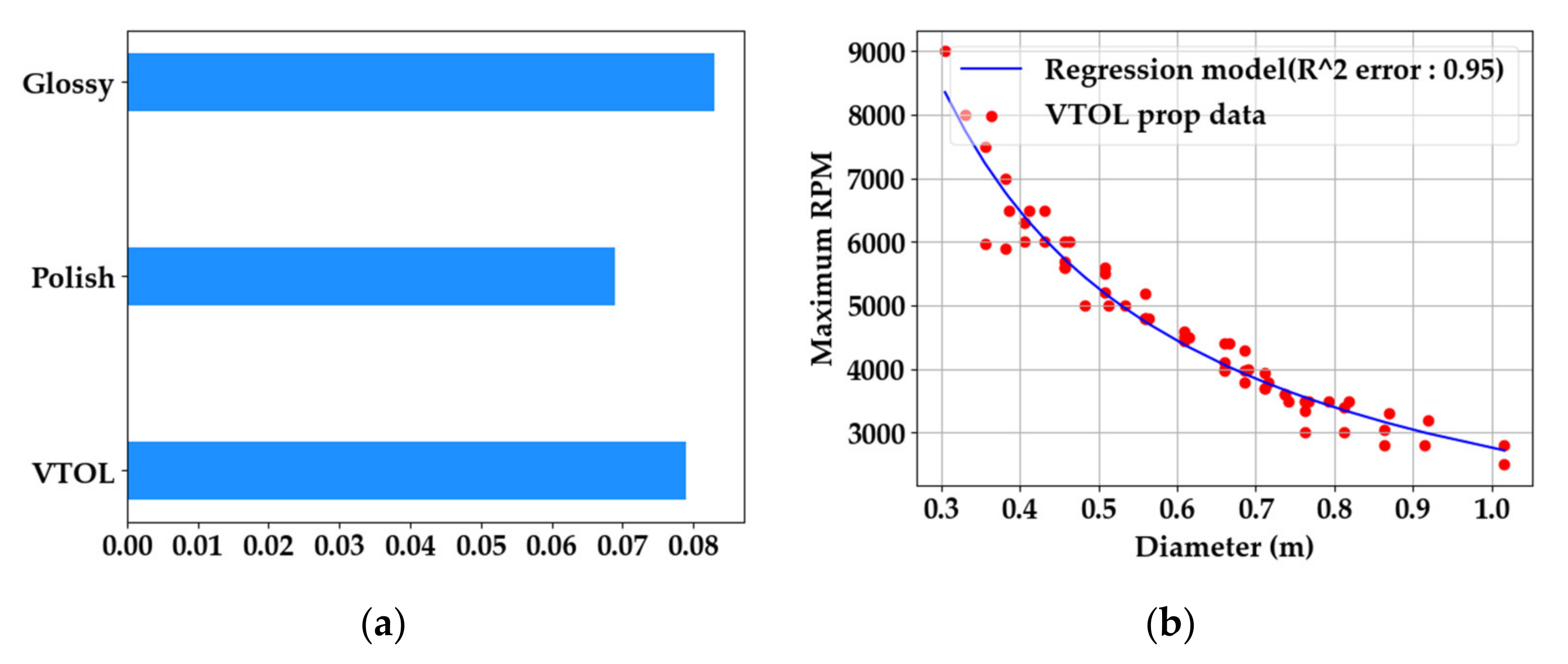
is the solidity of the VTOL propeller, and it was assumed to be 0.077 with reference to the data of the existing T-motor VTOL UAV propeller.
Figure 4a shows the solidity of the T-motor’s multi-copter propellers by series [
21].
is the tip speed of the VTOL propeller and is calculated as in Equation (9). To assume the rpm, the maximum rpm data for each diameter of approximately 70 VTOL propellers of the T-motor were collected as shown in
Figure 4b, and a regression model was made as shown in Equation (10) [
21].
is the vertical take-off speed, and
is the ratio of the total projected area of the UAV to the wing area, usually 1.3–1.4 [
13]. Finally, in order to maintain the VTOL mode with a stability at high altitudes, the VTOL ceiling constraint was set in the service ceiling. The RoC at the service ceiling of a low subsonic aircraft is typically 0.5 m/s. To consider the safety margin in the service ceiling, the ratio of air density should be applied to Equation (8). The ratio of the air density at the service ceiling to the air density at sea level can be calculated as in Equation (11).
Figure 5 is an example of a multi-mode constraint diagram that visualizes the design space and design point as a graph through the previously defined constraint functions. The
x-axis is
PL, and the FF mode and VTOL mode share an axis on the graph, but the values are different at the design point, and the
y-axis is
WL in the FF mode and
DL in the VTOL mode. In the example diagram, the blue area represents the design space of the FF mode, and the red area represents the design space of the VTOL mode. All points within the design space are feasible points, and the selection of design points was decided by the designer. Gudmundsson and other classical sizing methods suggest that design point at the constraint analysis should be to minimize wing area and required power [
12]. In this paper, in the same context, the initial point for sizing was selected as a point that minimizes the wingspan and minimizes the FF/VTOL power, which is shown in
Figure 5.
5. Electric Power System (EPS) Sizing
The EPS includes the motor, ESC, propeller, and HFC. Since only limited parameters are given during the sizing process, a regression model can be constructed based on the EPS data of the existing UAV, and sizing can be performed through this model. To construct the regression model, appropriate parameters should be selected, and the accuracy of the model should be verified by calculating the
R-squared error. In this paper, the regression model was created through the “curve_fit” module of Python SciPy optimize [
22].
5.1. Motor Sizing
Figure 6a,b are the regression model generated by collecting data from the products of the T-motor [
21], Scorpion motor [
23], and Hacker motor [
24] which are representative UAV motor manufacturers.
Since the motors for the FF and VTOL have different characteristics, a regression model was also generated separately. The input for motor sizing uses the maximum power calculated through the
PL defined in the MCA so that the motor can be operated without burn in all mission sections. Equations (12) and (13) are the regression models for sizing the FF and VTOL motors, respectively.
Here, the maximum power means electrical power, and it is a value that considers the efficiency of the motor from the mechanical power calculated through PL, and the efficiency of the motor is usually approximately 90–95%.
5.2. ESC Sizing
The ESC used for the eVTOL UAV is usually selected to accommodate the peak current required by the motor. Therefore, a regression model was built so that the maximum current divided by the maximum electric power by the rated voltage could be used as a sizing input.
Figure 6c is the regression model generated by collecting data from the products of the Hobbywing [
25]. In addition, Equation (14) is the regression model for sizing the ESC.
Here, is the rated voltage used in the UAV, which is the same as the rated voltage of the battery.
5.3. Propeller Sizing
Propeller sizing predicts the diameter of the propeller and predicts the weight accordingly. The area of the VTOL disk can be calculated as in Equation (15) through the
DL among the design variables defined by MCA. The area of the VTOL disk calculated here is the sum of the area of the entire disk, and the disk area of a single propeller must be divided by the number of VTOL propulsion systems.
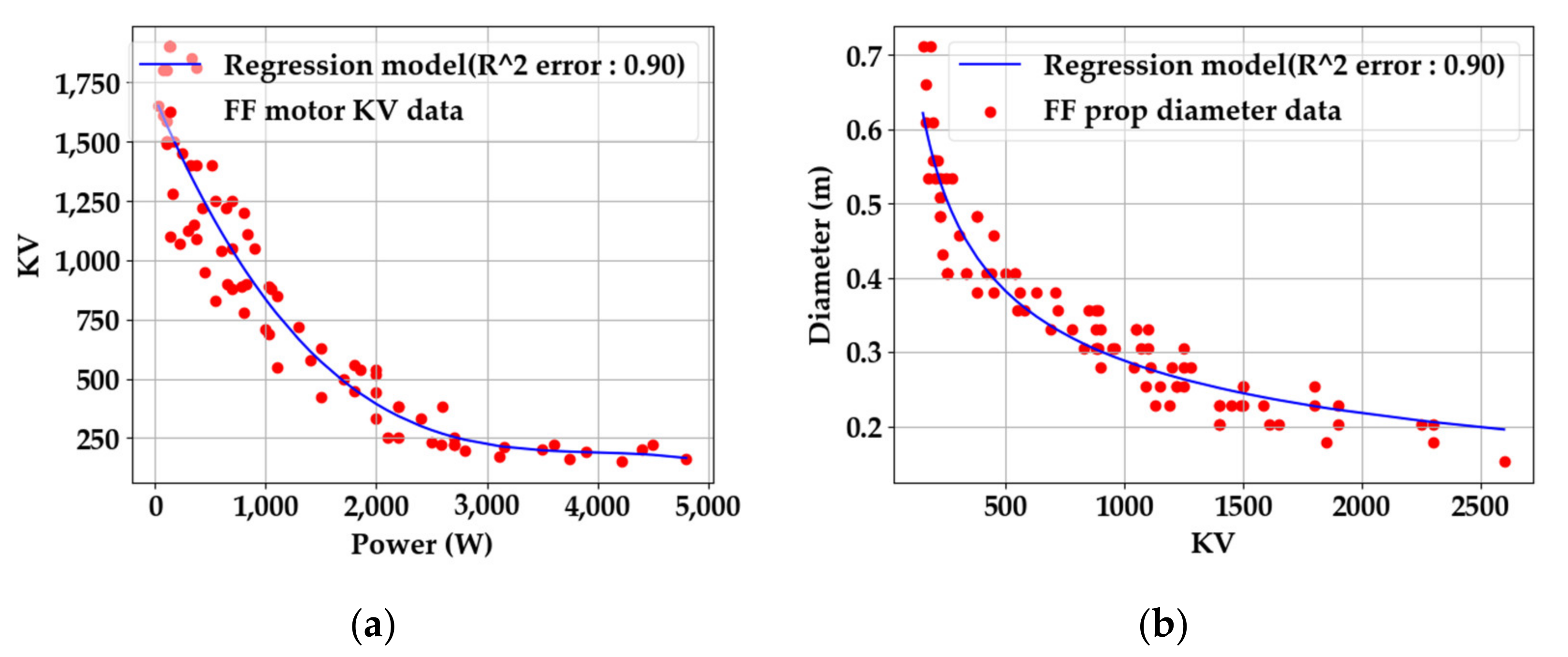
Unlike the VTOL propeller, the FF propeller requires many variables to determine the diameter. The thrust and power generated by the FF propeller are determined by the diameter, pitch angle of propeller, forward speed, and rpm of the FF propeller. However, propeller sizing considering all these parameters in the early design stage is not possible. Therefore, the diameter of the propeller can be predicted by generating a regression model for the motor power and
Kv, which means rpm per 1 volt and the most critical parameters in determining the diameter of the propeller.
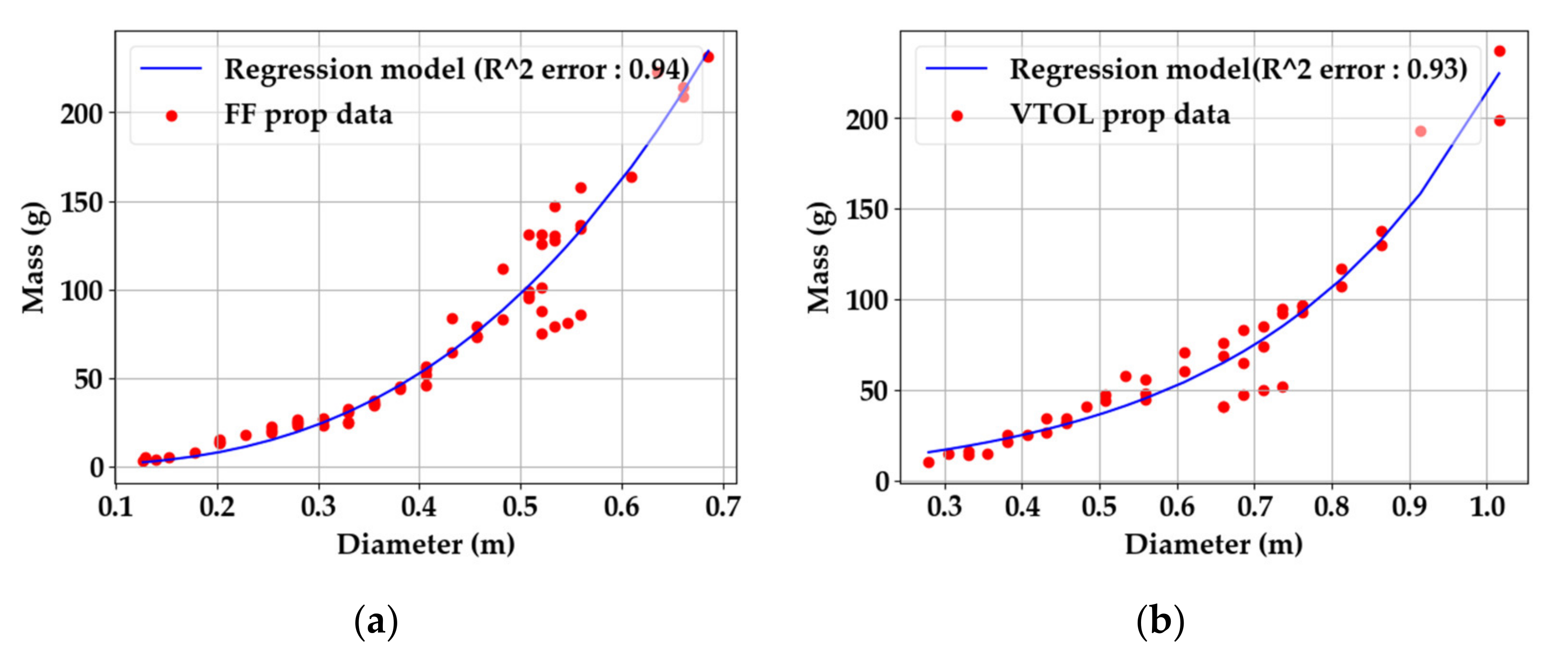
Figure 7 shows the regression model of the maximum power and
Kv of the FF motor and the regression model of the appropriate diameter of the FF propeller according to the
Kv of the motor.
Equations (16) and (17) are regression models for estimating the FF motor
Kv and FF propeller diameter.
FF propellers and VTOL propellers have different pitch angles and structures due to the fact of their different operating characteristics; thus, the data on weight are also different. Therefore, the regression model for estimating the weight of the FF propeller and the VTOL propeller should be generated separately, and the regression model configured in
Figure 8 is shown. For the FF propeller data, the APC propeller’s data were referred to in [
26], and for the VTOL propeller, the T-motor’s propeller data were used [
21].
The regression model consists of the weight according to the diameter of the propeller, and Equations (18) and (19) are regression models for sizing of the FF propellers and VTOL propellers, respectively.
5.4. Electric Branch Mass Calculation
Through the results of the motor, ESC, and propeller sizing, the weight of the electric branch can be calculated as in Equation (20):
Here,
is the weight of the parts necessary to mount the electric branch to the UAV, such as a motor mount and additional weight such as cables, and a value of approximately 1.2 is usually used [
13].
5.5. HFC Sizing
In the existing HFC UAV sizing study, specific power was used for HFC sizing. This can be usefully used when there is no information about the HFC in the early design stage such as sizing. The Department of Energy (DOE) set a target of 0.85 kW/kg specific power for an 80 kW (net) integrated transportation FC power system operating on direct hydrogen [
27]. Although this value is for a transportation application, the rated power is too large to be applied to a UAV, and the accuracy may not be high when applying it for sizing. Therefore, if the regression model was applied to the sizing through the HFC data currently used in the UAV, the weight can be predicted more accurately.
Table 5 shows the rated power, system weight, specific power, and HFC system configuration of the HFC applied to the UAV developed by HES Energy [
28], Intelligent Energy [
29], and Doosan Mobility Innovation [
30].
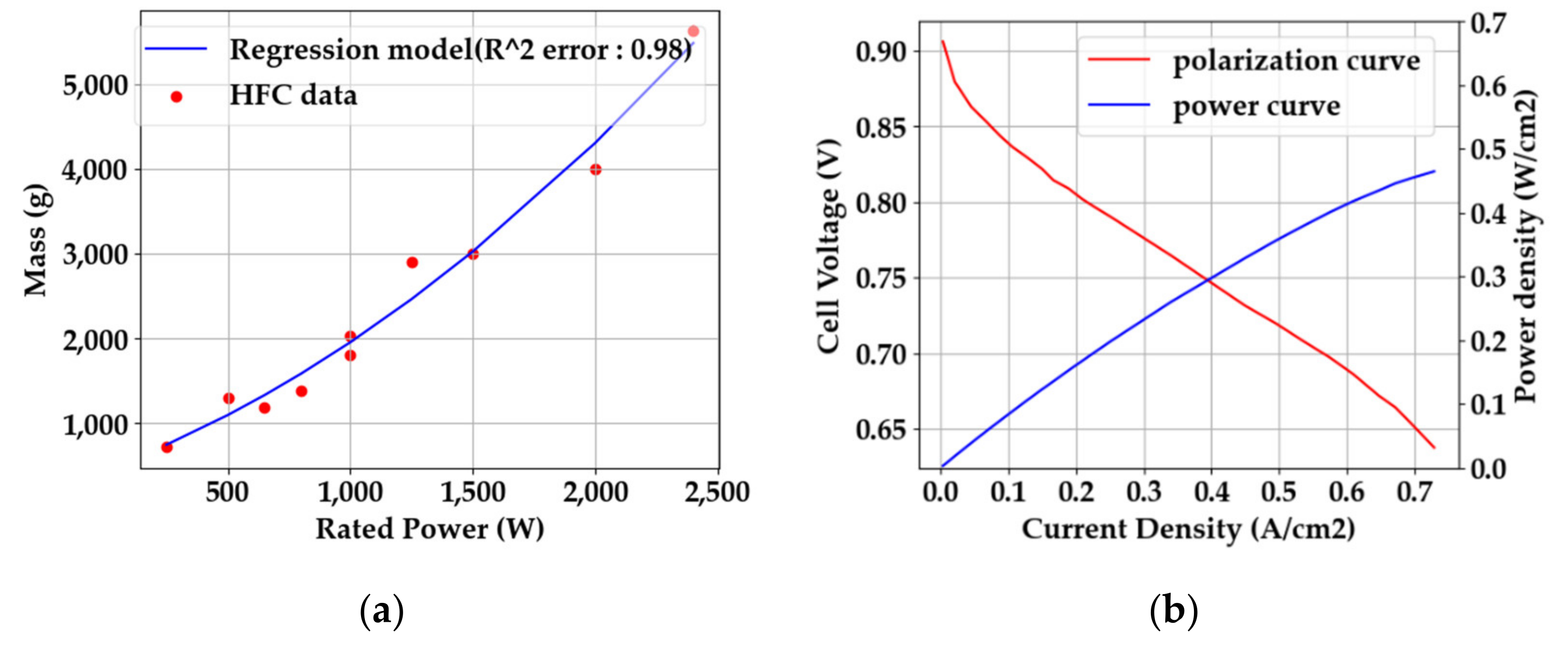
Using this data, a regression model for the weight according to the rated power of the HFC applied to the UAV can be generated as shown in
Figure 9a and Equation (21).
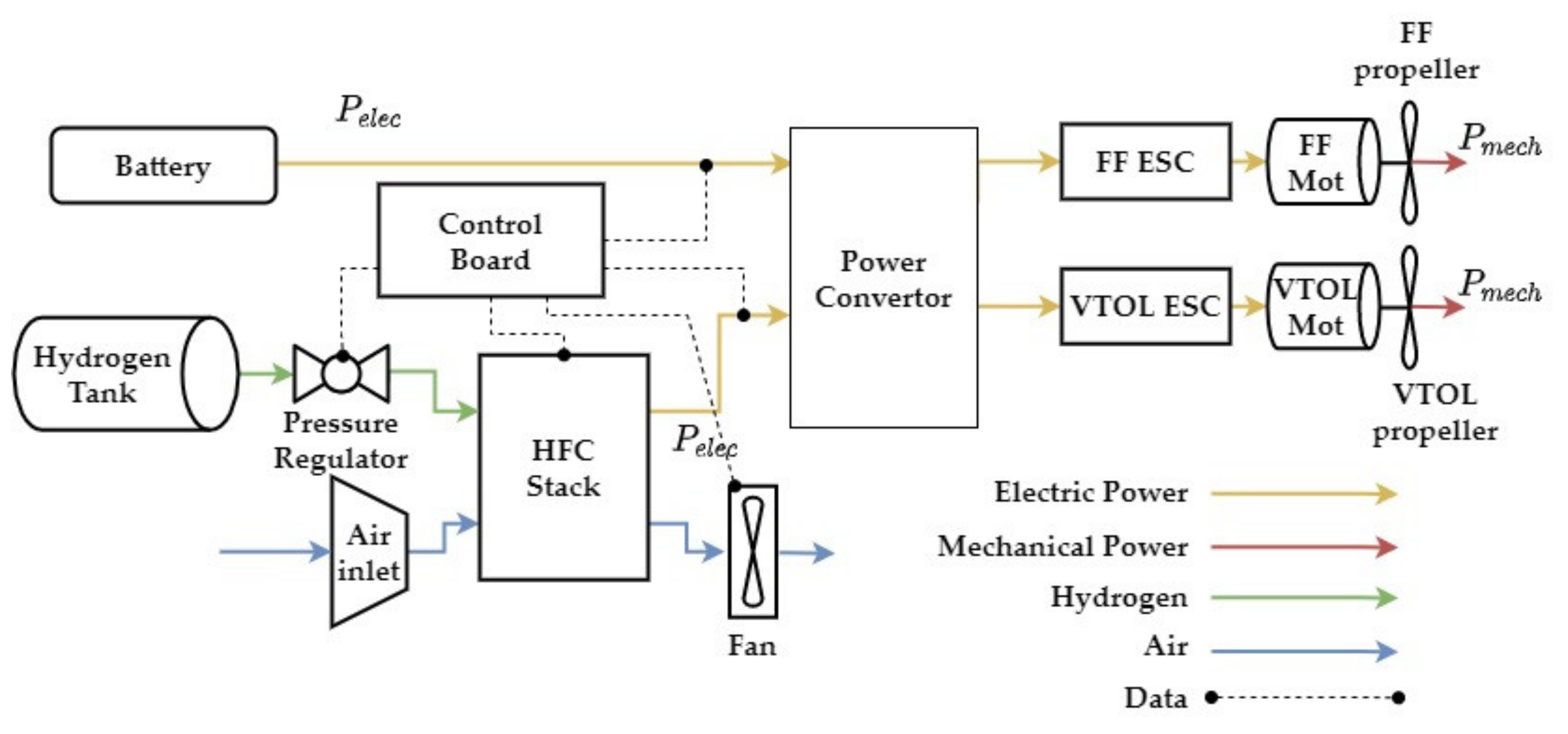
Using the regression model of Equation (21), it is possible to predict the weight reflecting the current technology level for the HFC applied to the UAV having the same configuration as in
Table 5. However, since not all HFCs have the above configuration, in this paper, another method for sizing the HFC based on the single-cell performance of the HFC is presented.
The polarization curve is a curve showing the trend of current density and voltage of a single HFC cell and is used to test the performance of that single cell. If the polarization curve is used, sizing can be performed based on the performance of the HFC to be applied to the UAV. The method of generating the polarization curve has been suggested through various references, and it can be generated in various ways [
2,
7,
31].
Figure 9b is an example of a polarization curve of the HES AEROSTAK 200W model [
2,
28].
In
Figure 9b, the power curve is a curve showing the trend in power density, which is multiplied by the current density and voltage. When the polarization curve is prepared, the number of cells constituting the HFC stack can be predicted as in Equation (22):
Here,
is the voltage of the HFC given in the design requirements, and
is the voltage of a single cell that maximizes the power density of the cell. If the number of cells in the HFC is determined, the electrode area of a single cell can be determined as in Equation (23). The electrode area means the area where the actual chemical reaction takes place.
Here,
is the power density of a single cell. The weight of the HFC can be predicted as in Equation (24) using the previously calculated information of the single cell [
7].
Here,
is the area density of a single cell, and Wanyi NG recommends
[
7].
is the ratio of the cross-sectional area to the electrode area of a single cell, and four is used as a conservative value.
is 0.3 as the overhead fraction for gaskets, seals, connectors, endplates, etc., constituting the HFC stack [
7].
is the ratio of the BOP weight to the HFC weight, and this value is different depending on the HFC configuration. In this paper, 0.2 was used in the case study.
One of the important parameters for prediction in HFC sizing is the efficiency of the HFC. At the current technology level, the efficiency of the PEMFC is approximately 40–50%, and if there is no information about the polarization curve of a single cell, this value can be used for sizing [
14]. However, when the polarization curve is defined, the efficiency of the HFC can be calculated as in Equation (25) [
32]:
Here, F is a Faraday constant of 96,485.4 C/mol, and is a chemical reaction energy of 284,000 J/mol. is the electrical power required by the mission operated by the HFC, and the efficiency of the HFC decreases as the required power increases.
7. Total Mass Calculation
The MTOW of the UAV is the most important parameter among the results of sizing and is calculated by adding up the weights of the components comprising the UAV calculated in the previous section. The total mass calculation was calculated through fixed point iteration, which is iteratively calculated until the MTOW converges below a predefined tolerance. The first iteration uses the initial MTOW given in the design requirement. For those of the components constituting the UAV that can be calculated, the actual value was added to the total weight through the methods presented above, and the remainder was calculated as the mass fraction, which is the ratio of the total weight [
13]. The items for which the mass fraction should be assumed are the air frame, avionics, and subsystem. For the air frame weight, it is recommended to use a mass fraction of 25–35% for the FF UAV as an initial estimation in sizing and 5% for the avionics [
34]. The mass fraction of the subsystem varies depending on the operation type of the UAV, which is 5–7% for UAVs designed for delivery and 15% for advanced surveillance equipment [
13]. The total weight of the multi-mode HFC eVTOL UAV was calculated as in Equation (35):
Here, is the weight of the entire hydrogen system, including the previously calculated HFC, tank, regulator, and control board. The calculated MTOW is used as a value for fixed-point iteration in the multi-mode sizing loop, and the multi-mode sizing loop is repeatedly calculated until the MTOW converges.
9. Case Study
The sizing methodology proposed in this paper was implemented in the 25 kg hydrogen fuel cell UAV design project. The quantitative goals were an MTOW under 25 kg, endurance up to 6 h, a hydrogen system mass under 10 kg (40% mass fraction), and continuous power of the HFC up to 2 kW. As a design process before sizing, requirements analysis and concept selection were performed.
Table 8 shows the design requirements derived through the requirements analysis, and the concept of operation for this UAV was surveillance.
Figure 14 shows the mission profile of the surveillance HFC UAV.
The results of the sizing are compared with the conceptual design results of the UAV to validate the accuracy of the methodology. An integrated analysis and configuration optimization of the UAV were performed with the Konkuk University in-house program ADSP (Aircraft Design and Synthesis Program). ADSP can perform multi-disciplinary analyses and optimizations of UAVs as well as very light aircrafts (VLAs), UCAVs, and electric aircrafts, and its accuracy and efficiency have been verified [
35,
36,
37]. In addition, CFD for high-fidelity aerodynamic analysis and wind tunnel experiments for obtaining high-fidelity electric propulsion system performance data were performed to construct high-fidelity analysis data and, thus, the design results are very accurate. The HFC stack and BOP were designed by Nexcoms Co., Ltd., and the HFC sizing result was verified through the data of the developed product [
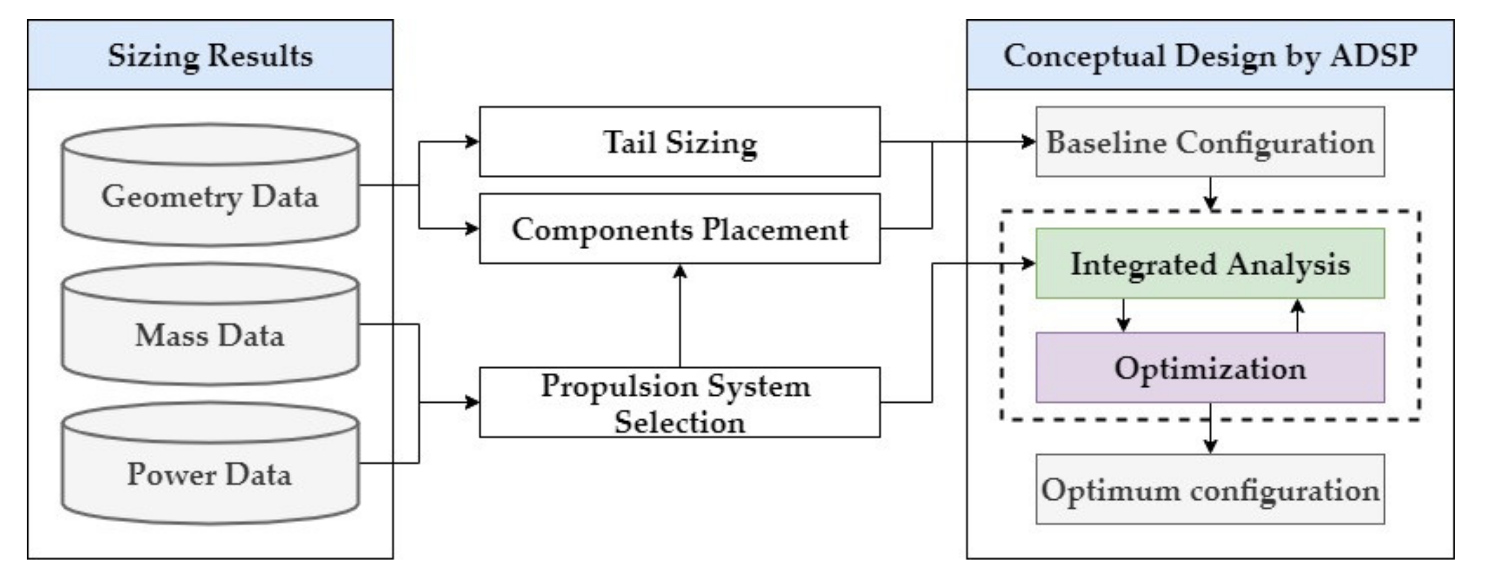
38]. The conceptual design process through ADSP proceeded as shown in
Figure 15. Based on the sizing result, the propulsion system was selected, components placement performed, and then the conceptual design was carried out through multi-disciplinary integrated analysis and optimization.
9.1. Optimum Sizing Result
Table 9 shows a comparison between the sizing result and the conceptual design result. Initial sizing refers to the sizing result at the initial design point selected by the designer before optimization, and optimum sizing refers to a design point that satisfies the design requirements through optimization.
When comparing the error between the sizing result and the conceptual design result, the error for all parameters was within 10%.
Table 9 shows that the initial sizing result did not satisfy the design requirements. This is because, as mentioned above, the initial point was determined in a design space that satisfied only the performance requirements defined by MCA. On the contrary, the sizing result satisfied all the design requirements.
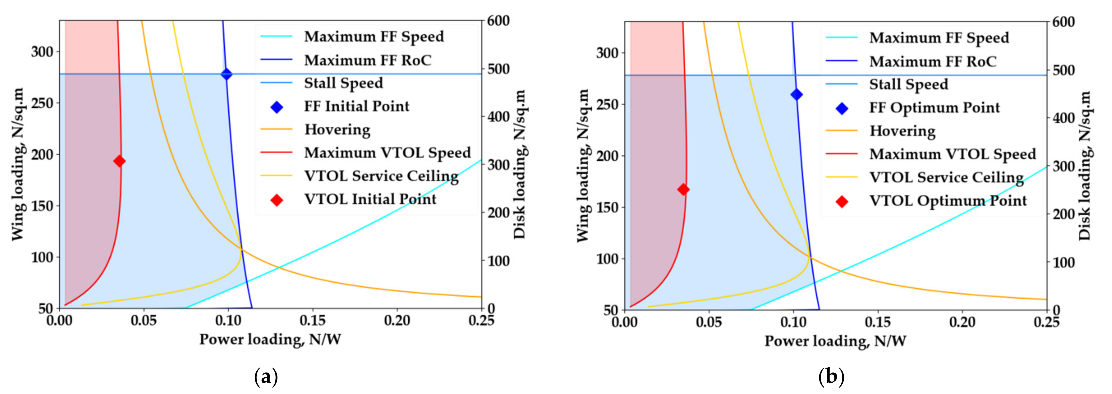
Figure 16 shows the initial point and the optimum point.
Figure 16 shows that the optimum point shifted to a point that could minimize the MTOW while satisfying the design requirements within the design space defined by MCA through the optimization process.
Figure 17 shows the configuration change in each stage of the concept sketch, sizing, and conceptual design. In the sizing result, only the AR, area, and span of the wing are given, so it is a rectangular wing shape. In the conceptual design stage, ADSP is used to optimize geometry parameters such as the sweep angle and taper ratio of the wing.
9.2. EPS Sizing Result
For the sizing result of the EPS, the accuracy of the sizing was analyzed by comparing the mass of the motor, ESC, and propeller applied to the actual UAV and the HFC data, which was developed by Nexcoms.
Table 10 shows the comparison of the motor, ESC, and propeller sizing results with the actual mass data.
In the conceptual design process, the FF motor was selected according to the maximum power required in the FF mode, motor weight, and
Kv predicted in sizing, and the VTOL motor was selected according to the maximum power required in the VTOL mode and the motor weight. After that, the appropriate ESC and propeller for the motor were selected. In the process of selecting a motor with the most similar
Kv while satisfying the maximum required power for each flight mode and motor weight calculated from the sizing result, it may not be possible to find a motor that satisfies them all, and an error occurs in this process. Errors may occur in other components as well. However, the error for all components between the actual data and the sizing result was within 10%, which means that the accuracy of the sizing method through the regression model developed in this paper was high and the parameters constituting the regression model were appropriate. For the HFC, the data of the HFC developed by Nexcoms in
Figure 18a and the sizing result were compared.
Table 11 shows the comparison of the HFC sizing results and Nexcoms’ HFC’s actual data. The HFC sizing was based on the single-cell polarization curve of the Nexcoms HFC, and the error is under 10% for all parameters, which means that the HFC sizing methodology proposed in this paper is very accurate.
Figure 18b is one of the results of HFC sizing, which is a graph showing the efficiency according to the operating power of the HFC. It is used for hydrogen tank sizing in mission analysis. Since the efficiency of a hydrogen fuel cell decreases as the power required increases, as shown in
Figure 18b, two HFCs were therefore used to lower the power requirement and increase the efficiency in this project.
9.3. Mission Analysis and Transition Analysis Result
As for the result of the mission analysis, the accuracy of the methodology was verified by comparing the sizing result of the required power for each mission segment with the mission analysis result through ADSP.
Figure 19 shows the sizing result for the required power for each mission segment and the mission analysis result through ADSP.
The ADSP mission analysis is highly accurate because it uses the results of aerodynamic analysis through the CFD and wind tunnel test results of the electric propulsion system. In addition, because the maximum error in each mission segment was calculated to be approximately 15%, this means that the sizing result was relatively accurate.
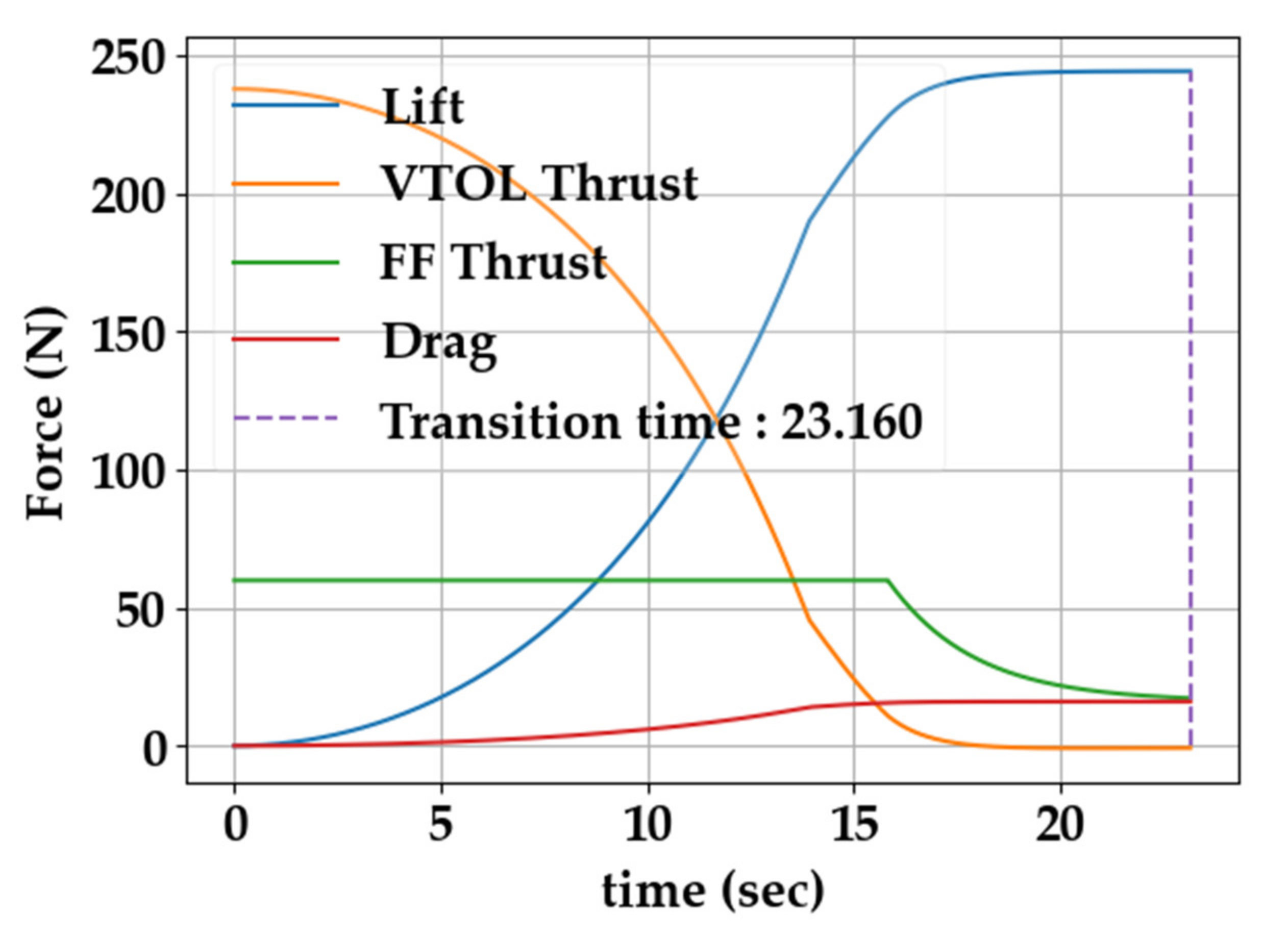
Figure 20 shows the results of the transition analysis.
Through the transition analysis results, the methodology proposed in
Section 6.2 satisfies all the assumptions for transition, and it is possible to predict the transition end time and required power during transition for battery and hydrogen tank sizing. The transition end time was predicted to be 23.16 s. And
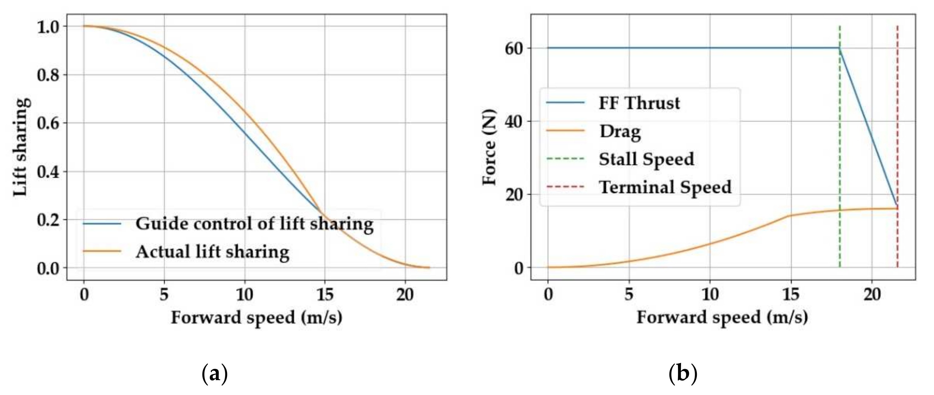
Figure 21 shows the change in lift sharing, speed, and angle of attack during the transition of the UAV as one of the results of transition analysis.
As mentioned in
Section 6.2, the lift presented by the guide control of lift sharing could not be generated at the beginning of the transition due to the insufficient forward speed. Therefore, the angle of attack was maintained at the maximum as shown in
Figure 21c, and the lift sharing was performed as
Figure 21a. After the forward speed was sufficiently increased, the UAV generated the lift force presented by the guide control, and the angle of attack decreased accordingly and converged to the trim angle of attack in the terminal condition.
Table 12 shows the comparison of the battery and hydrogen tank sizing results and the battery and hydrogen tank data applied to the actual UAV through the calculation of the required power for each mission segment.
The battery applied to the UAV was two packs of the EP Power 22.2 V 3800 mAh 55C model [
33], and the hydrogen tank was the CTS Ultralight 13 L Type 4 model [
40]. The error between the sizing results and actual data of the battery and hydrogen tank was under 10% for all parameters, which means that the battery and hydrogen tank sizing methodology based on the regression model proposed in this paper was accurate.
10. Conclusions
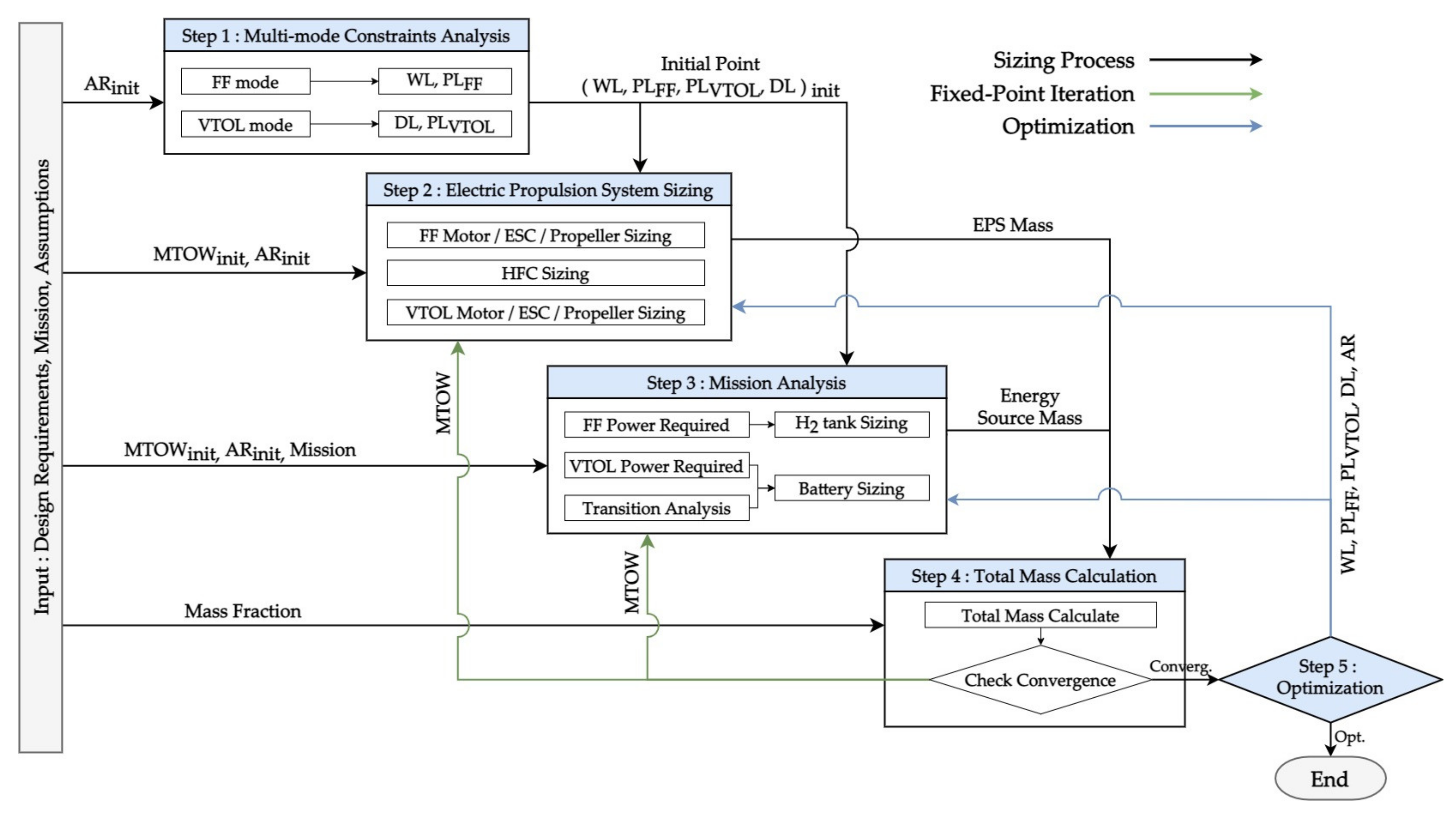
This research presented an improved sizing methodology for a multi-mode eVTOL UAV using a hydrogen fuel cell and Li-po battery. Sizing involved five major procedures. First, the MCA added the performance requirements of the VTOL mode through disk loading so that it can be applied to the multi-mode eVTOL in the existing constraints analysis. Second, for EPS sizing, a sophisticated regression model with an R-squared error of 0.9 or more was built through the data of the existing UAV propulsion component. Through this, the motor, ESC, and propeller sizing methodology was presented, and in the case of the HFC, a sizing technique using the polarization curve of a single cell was presented. Third, mission analysis presented a method of sizing the capacity and weight of the Li-po battery and the weight and volume of the hydrogen tank through the required power defined for each mission segment, and it also presented a new analysis method for the transition mode. The fourth total mass calculation calculated the MTOW of the UAV and performed fixed-point iteration until the MTOW converged. Finally, an optimization method for optimizing the wing loading, power loading, disk loading, and AR was presented so that the sizing result satisfied all the design requirements.
To verify the accuracy of the sizing methodology presented in this paper, the sizing of a 25 kg hydrogen fuel cell UAV was performed. The accuracy of the sizing was verified through comparison with the conceptual design results performed using ADSP based on the sizing results. As a result of the sizing, the MTOW was minimized at 24.91 kg while satisfying all the design requirements. Since the propulsion system selects the product with the closest performance based on the parameters calculated in sizing during the conceptual design process, errors may occur in the sizing result. In addition, because the geometry data of the UAV wing uses the sizing result as the initial configuration in the conceptual design process and is optimized in consideration of stability, errors may occur with the sizing result. Nevertheless, all the parameters had an error of less than 10% compared with the conceptual design results, which means that the sizing methodology presented in this paper is very accurate and sufficient to be used as initial design data. Therefore, the sizing methodology presented in this paper is a useful tool in the design of UAVs using hydrogen fuel cells and batteries, and if the regression model is replaced with one on a larger scale, it can be usefully for the sizing of urban air mobility (UAM) vehicles.

