1. Introduction
UAVs are currently becoming popular due to their high maneuverability, good performance, low cost, and reliability [
1,
2]. By 2021, the target of the drones market is estimated at 4.5 billion US dollars and will reach 10.4 billion US dollars by 2031 [
3]. Controlling a UAV from a ground control station (GCS) provides a new possibility for the UAV to reach the furthest areas with few human resources needed and require minimal energy, time, and effort. Recent technological advances create more new possibilities for UAVs [
4,
5], and UAVs are employed commonly in tasks such as surveillance [
6], search and rescue missions [
7] in the disaster area, wildfire, tracking, borderline security [
8], remote sensing of the environment [
9], etc. This is one of the biggest reasons UAVs are being adopted worldwide, especially by these sectors: personal, commercial, military, academia, and future technology.
Flight control software (FCS) is required to control and monitor UAVs from GCS [
10]. Necessary characteristics of the software are (1) navigation, (2) guidance, and (3) control. Navigation is the process of data acquisition, data analysis, and estimation of information about vehicle state and its surrounding environments. Several fundamental sensors are used in the navigation process: an accelerometer, gyroscope, magnetometer, GPS, and other peripheral sensors such as airspeed sensor, barometer, etc. Guidance is the process concerned with user input, such as path planning, mission planning, flight mode changing, etc. The control component ensures that the flying vehicle follows the desired path and altitude by manipulating control surfaces. Employing UAVs in different fields requires modular and portable software that can expand quickly based on increased functionality. When functionalities and requirements of the software increase, the software can fulfill new functionalities and requirements by developing (or porting) a new module (from other software).
Software (or software module) portability is an important feature of the software, as it enables the software (or software module) to be reused in other software tools and/or operating environments [
11]. When the design of a software does not consider portability and was not developed in modules, it is not possible to adopt the software in a new environment. This is because the software must be redesigned, reconfigured, and modified significantly to be able to run in a new system. Converting non-portable software to portable software is very costly because most of the conversion needs to be processed manually, and it also has to be tested for conformity [
12,
13]. By porting the software (or expanding with modules of other software) from one environment to another, major economic savings can be achieved by dropping out the development and modification costs of the software [
14].
In order to be portable, the software must satisfy the portability requirements such as layered and modular structure, loosely coupled and high cohesion on its modules, standard interfaces, and hardware abstraction layer (HAL) [
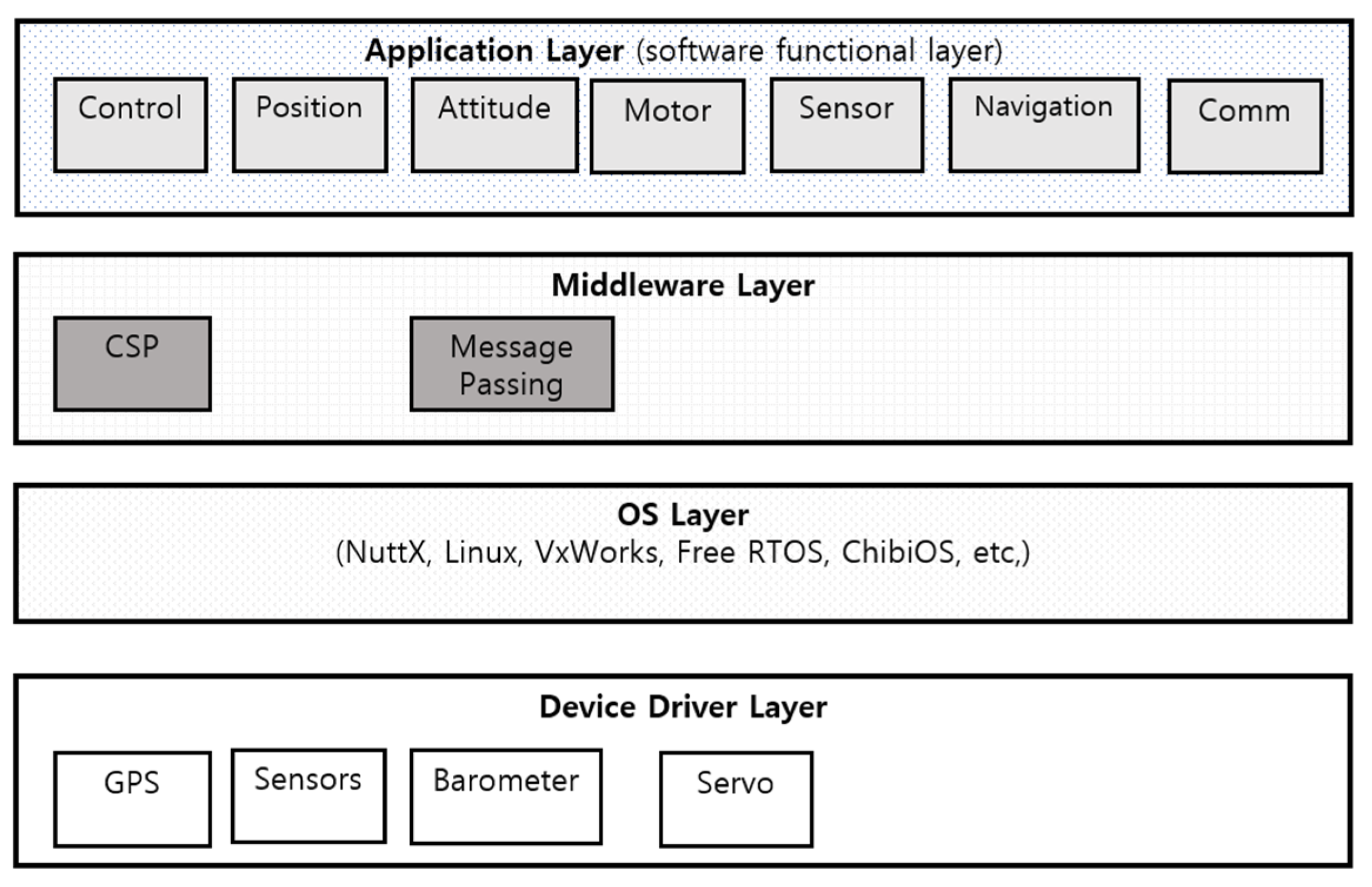
15]. These requirements result in easy expandability of the software. In order to be expandable and portable, many UAV software followed a layered structure with different modules and centralized all message-passing services between its modules as a middleware. The structure of existing UAV software [
6,
7,
8,
9,
10,
16,
17,
18,
19,
20,
21,
22,
23] consists of common layers that contain different modules, such as
a hardware layer responsible for interface to the device,
a middleware layer, which works as a bridge between the hardware layer and application layer, and
an application layer that contains various functional modules, including navigation, guidance, and control modules.
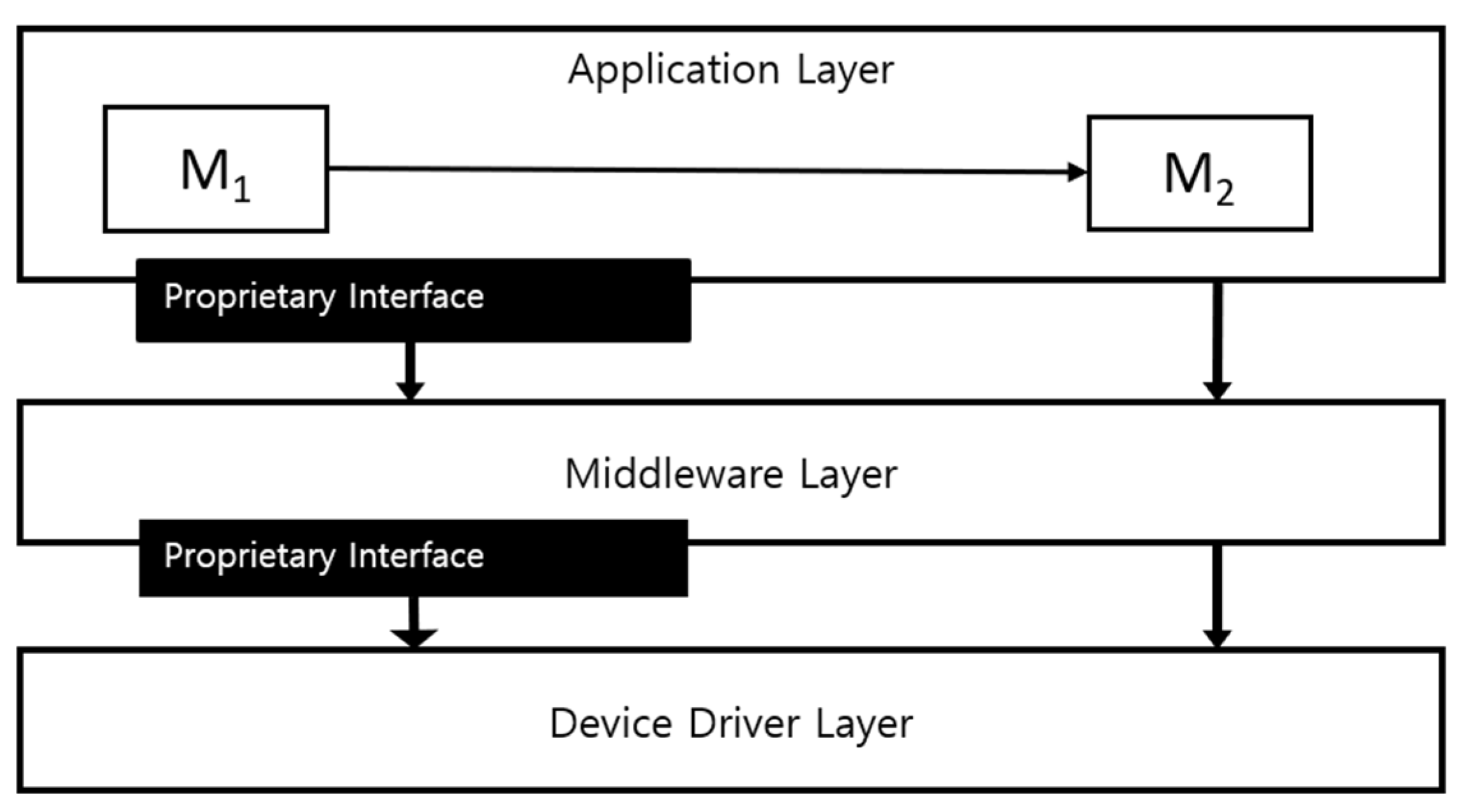
Unfortunately, existing software does not satisfy all requirements and fulfills only some of them. Each software provides unique interfaces for communication between modules. These unique interfaces introduce a barrier to the portability of the modules and provide more complexity to the software and bring tight coupling into modules.
Due to its tightly coupled modules, the existing software cannot provide portability into its modules, and it is not easy to extend the software with new modules and transfer its modules to a different environment. Despite the technical advances, many software today result in the tightly coupled integration of software modules without regard to portability. This lack of focus on portability results in software modules that are unable to be reused from one software to another without significant modification.
This paper proposes a new structure of the flight control software of UAV named
mpFCS (module-level portable Flight Control Software) that can provide portability to the software and each software module. In order to eliminate tight couplings and provide portability for its modules, we isolated its modules and designed the structure of the software. To design a new structure, we analyzed the structure of existing software at its module level. To do this, we used the standard FACE (Future Airborne Capability Environment) architecture for airborne software, and a new structure is based on specifications and requirements of the architecture that provides portability to the software. The FACE standard architecture [
24] defines interfaces intended to develop software made up of portable components. The
mpFCS consists of different portable modules in different segments, which can send and receive a message between its modules and between the software and GCS. We implemented a new structure with its core modules: flight mode, attitude, position, servo control, sensor, communication, transmitter, and IO module. Each module uses the FACE standard interfaces to transfer data between its modules. We evaluated the software with the FACE conformance test suites.
The result shows that each module of our software is portable to the different software that runs in the FACE environment, and they are also interoperable with the different software modules that use the same interfaces. Furthermore, to prove its expandability, we developed a sample module and ported it into our software. The result shows that the structure is expandable with a new module.
The main contributions of the work are as follows:
Framework for providing module-level portability for the software: we propose the framework that can provide portability to the software. The framework not only provides portability to the software, but also provides its modules.
Portable and expandable software with module-level portability: The proposed structure mpFCS provides portability for the software as well as portability for its modules to run in the standard FACE environment. The software based on the structure can expand with any new user-defined module or previously well-developed module that uses the standard FACE interfaces.
The software can be used as a prototype of actual FACE software. It means developers can test their software or module with actual FACE-based software.
Guideline for creating a portable module or converting the current module into a portable module. The guideline provides steps of analysis and how to do it.
The remainder of this paper is organized as follows.
Section 2 explores related work, and
Section 3 introduces a problem of the existing software and its causes. The solution for the problem and the proposed structure
mpFCS are described in
Section 4. Then,
Section 5 explains the overall design of the
mpFCS and its modules.
Section 6 discusses the implementation of
mpFCS.
Section 7 provides experiments, results, and discussion. Finally, we conclude the paper in
Section 8.
4. Solution
This section introduces a new structure of the software named
mpFCS that provides portability to its modules. First, the section describes the main specification of the common modules, and then the section continues our design strategy for bringing portability to modules. We analyzed the structure of the existing flight control software, its modules, and connection methods between its modules and then segmented it into the FACE architecture [
24], which provides airborne software’s standard interfaces and architecture. Bringing the standard architecture into the UAV flight control software provides portability to the module.
4.1. Standard for the Portability Problem
Owing to the software’s tightly coupled modules in the different layers, it is not easy to port the software and its modules in a different environment without modifying the source code. In order to solve this problem and enable portability to the software, we choose the FACE (Future Airborne Capability Environment) architecture.
Figure 3 explains the overall design of the FACE architecture, which can provide portability into the software modules.
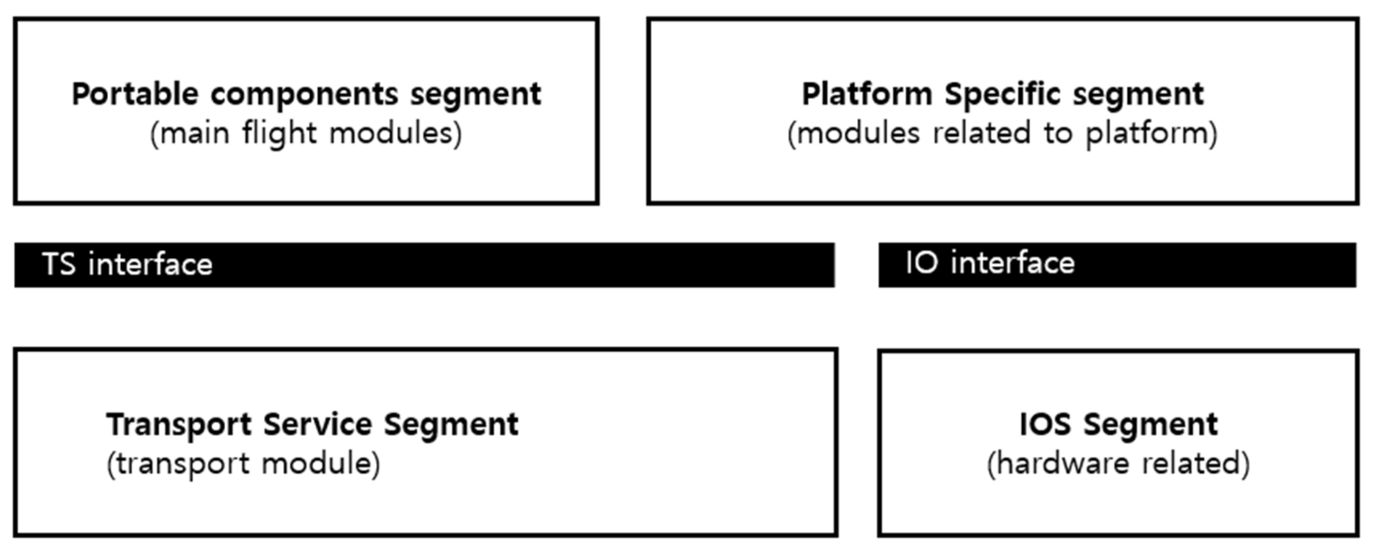
The FACE architecture from the Open Group provides portability to airborne software that can be redeployed on different computing hardware and/or the standard airborne software environment. The FACE architecture is composed of five logical segments:
The Operating System Segment (OSS): It provides and controls access to the computing platform for the other FACE segments.
Input/Output Services Segment (IOSS): It is a bridge for data from the device drivers to the PSSS.
Platform-Specific Services Segment (PSSS): It creates an infrastructure unique to the platform that provides device data to the components located in the Portable Component Segment.
Transport Services Segment (TSS): It provides movement of data between PCS and PSSS.
Portable Components Segment (PCS): It is a set of portable components.
The architecture defines a set of standardized interfaces providing connections between the FACE architectural segment such as Operating System Segment Interface (OSS Interface), the Input/Output Services Interface (IOS Interface), the Transport Services Interfaces, and Component-Oriented Support Interfaces. Additionally, the architecture defines the Unit of Portability (UoP), a set of components that provides one or more mission-level capabilities. The main characteristic of UoPs is portability to the other software that follows the FACE architecture. In this paper, we use the word module instead of the abbreviation UoP, which means the word module and UoP are interchangeable and have the same meaning in our work [
24].
4.2. Restructuring Process
To follow the FACE architecture, first, we need to understand the structure of the existing software and its module’s dependencies and design its structure via following the specification and requirements of the FACE architecture. To achieve the above specification, we analyzed various UAV software and matched similar software layers into the FACE segments depending on each segment’s functionality and requirements.
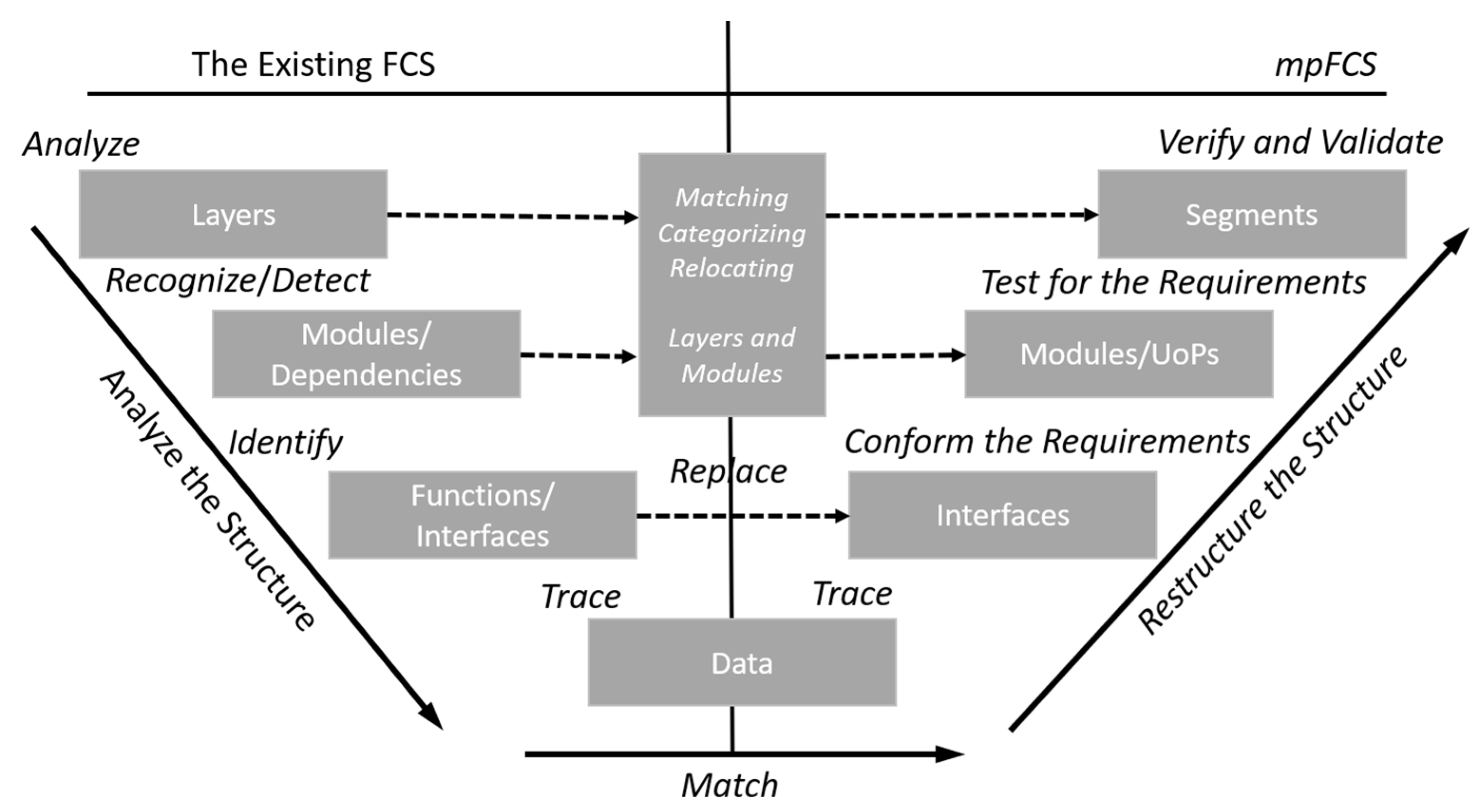
Figure 4 shows the matching process of the existing software into the FACE architecture. We called this process the AMR-Process (Analyze, Match, Restructure Process). It consists of two phases: analyzing the structure phase and redesigning the structure phase.
In the phase of analyzing the structure, we followed the steps below to analyze the structure of the existing software.
Analyze the software layers.
Recognize the modules and detect their dependencies.
Identify the functions and interfaces between modules.
Trace data between the functions to match the data for the next phase.
In the restructuring phase, we match the modules with the FACE segments based on analyzed data from the previous phase, the main requirements of the FACE architecture segments, and interfaces. Due to functions, dependencies, interfaces between modules, and input/output data, modules in the application layer match the PCS of FACE architecture. The modules in the middleware layer are divided into the TSS and PSSS, depending on their functionality and dependencies. The device driver layer matches with IOS because of its role in the software.
After identifying and analyzing module dependencies, we replace the software’s propriety interfaces with the FACE standard interfaces to transfer data. All the above processes result in portability to the software and its modules on the FACE software environment.
4.3. The Proposed Structure: mpFCS
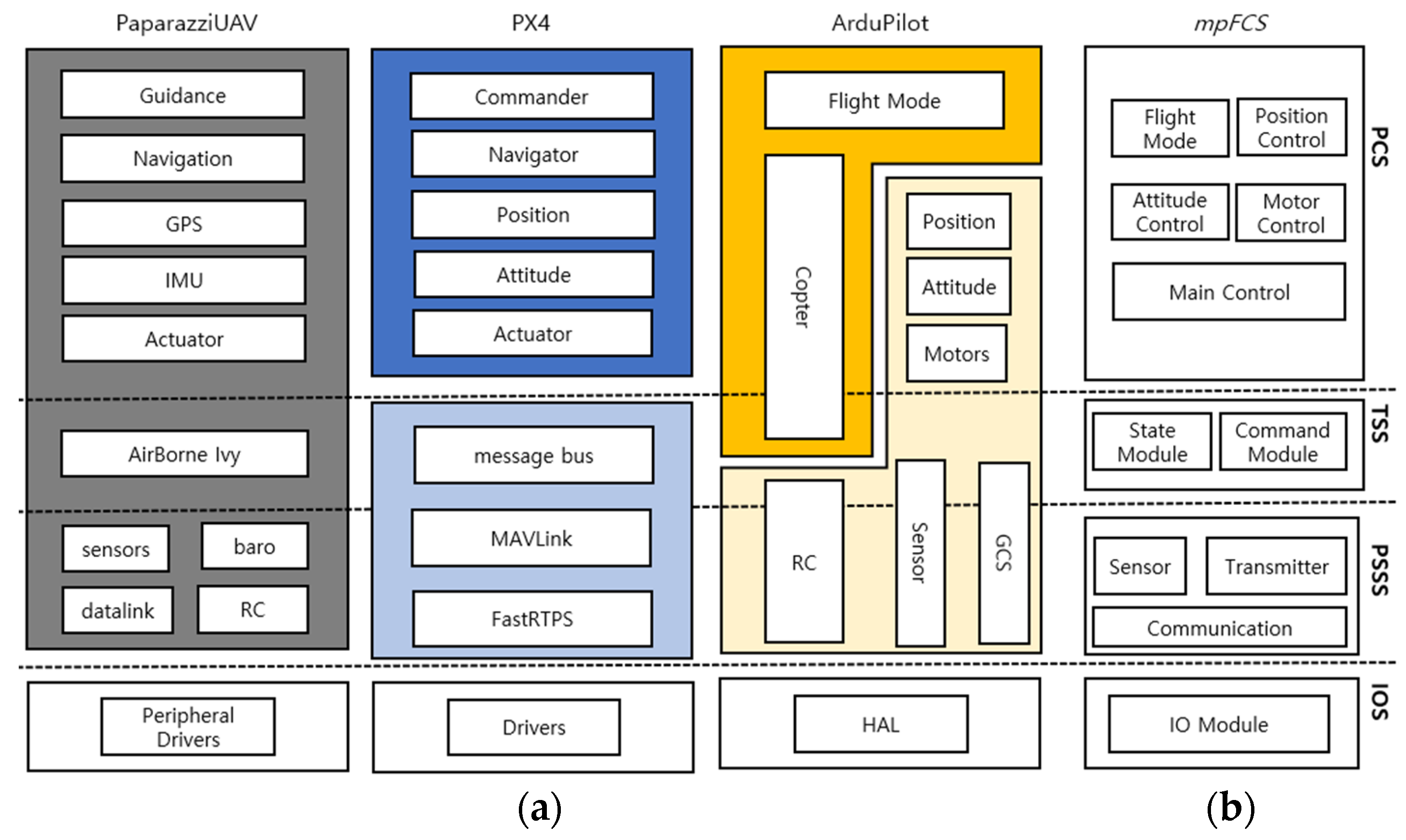
In order to validate the AMR-Process on different types of software, we choose the software that (1) is open-source, (2) is currently effective, (3) follows a common structure, and (4) has good documentation. The software that fulfill the criteria are PaparazziUAV, ArduPilot, and PX4. The result of the analysis phase is shown in
Figure 5a.
Based on the result of the analysis phase, we execute the restructuring process. Our proposed structure resulting from the redesigning phase has different layers and is modular, same as the existing FCS. It uses the FACE standard interfaces to transfer data instead of proprietary interfaces. Due to the standard architecture, it results in portability of the software and its modules.
Table 3 shows a general comparison of our solution with the existing FCS.
5. Design of the Proposed Structure: mpFCS
In order to solve the portability problem of modules, we followed the AMR-Process mentioned in the previous section on the structure of different flight control software and designed the structure. This section explains the overall design of the mpFCS based on the result of the analysis. Then, we explain each segment of the structure and its modules. The FACE architecture defines only the segments, interfaces, and requirements of each segment and interface. Thus, we placed modules of the software in the segments based on their requirements and specifications to follow the FACE architecture.
5.1. The General Structure of the mpFCS
Figure 5b shows the overall design of
mpFCS that proposed structure of UAV software with module-level portability, which is based on FACE architecture.
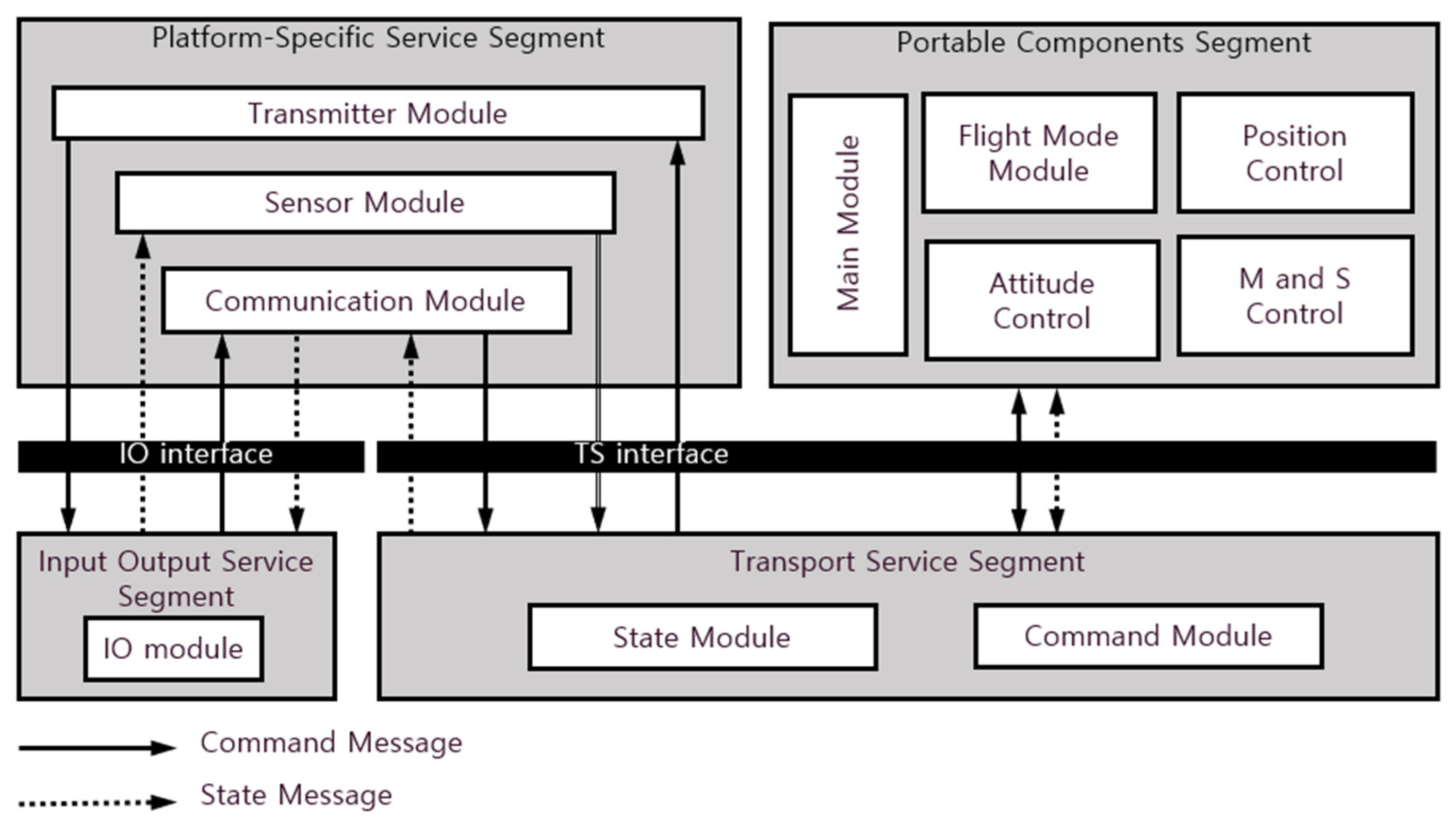
Figure 6 describes the data flow of all modules in the segments. The IO segment receives data and sends it to the platform-specific service segment via the IO interface. Based on the IO service segment’s output, platform-specific service segments calculate data and send the calculated result to the portable component through the transport service segment. The transport service segment uses transport interfaces to transfer data between the portable component and platform-specific service segments. On the other hand, to send a state message from UAV to GCS, the portable component segment transfers state data (GPS location, altitude, heading, IMU data, mission state) to the platform-specific services segment through the transport service segment. When the platform-specific services segment receives data, it calculates, converts, and sends the data to the IO services module via the IO interface.
Running the common and open source UAV software does not require a specific operating system, such as a real-time operating system (ARINC-653, POSIX, etc.). The software runs on open-source operating systems, including Robot Operating System (ROS), NuttX, ChibiOS, etc. The Operating System Segment of the FACE architecture is not included in our design and is not implemented. Nevertheless, since we use the FACE interfaces between the modules, porting the structure into such operating systems is not a problem.
5.2. IO Service Segment
The IO module in the I/O Service Segment (IOSS) is responsible for interface devices, and it connects hardware drivers with platform-specific modules, which is the basis of information between platform-specific modules and external devices. The module receives command data from the I/O device and passes them to the module in the Platform Specific Service Segment (PSSS). Concurrently, the module receives state data from the module in the PSSS. All input and output data between modules in IOSS and PSSS goes through the IO interface.
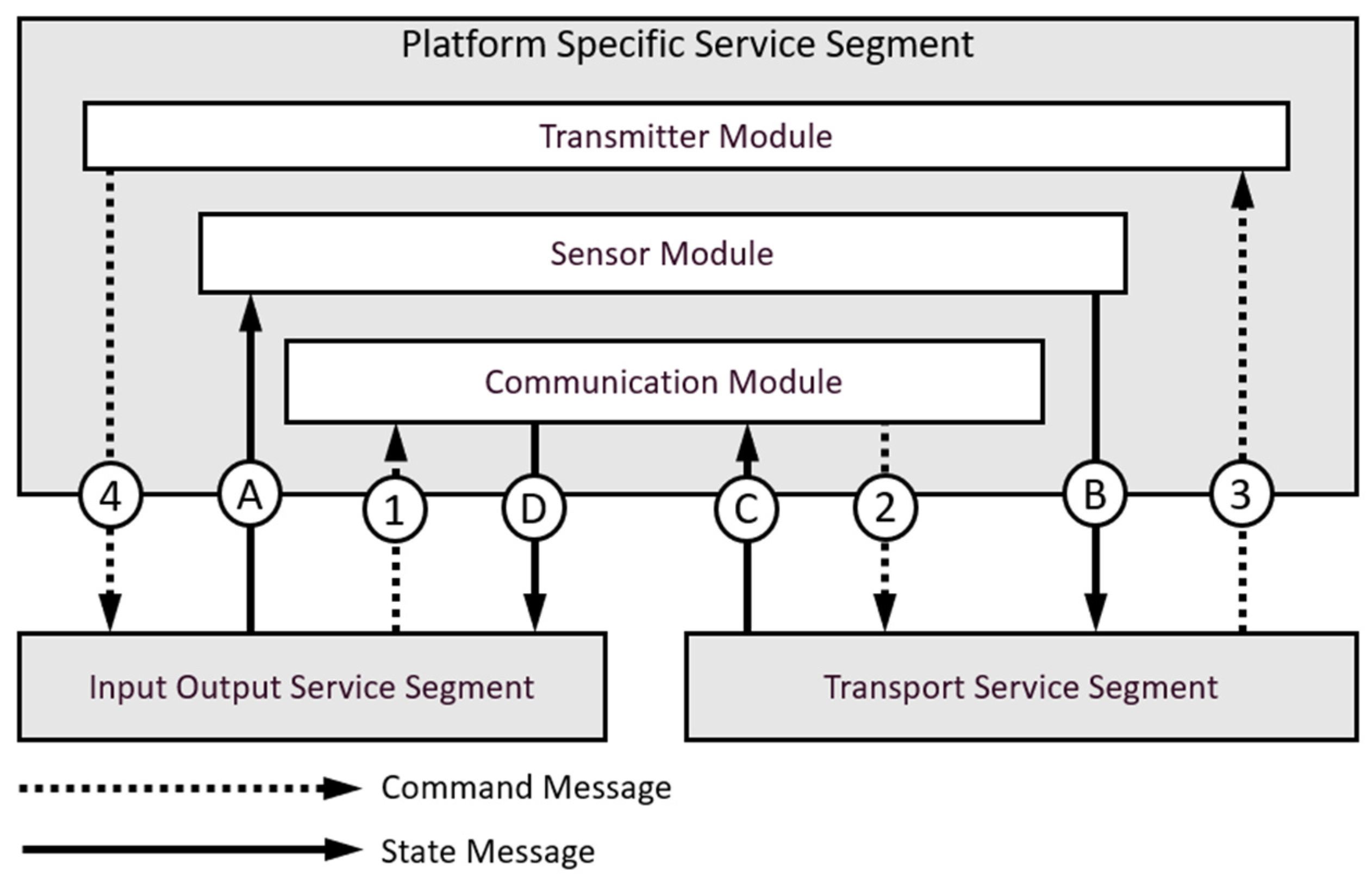
5.3. Platform Specific Service Segment
We designed modules in the Platform Specific Service Segment (PSSS) that depend on the IO module data, and all data flow in the PSSS is shown in
Figure 7.
The segment consists of three modules: sensor-calculation, communication, and transmitter modules. The segment receives data from the Transport Service Segment (TSS) or IOS and sends them to IOS or TSS.
The communication module is responsible for sending and receiving a message between UAV and GCS. It receives a command message from IOSS via the IO interface, then passes a message to TSS using the TS interface. Simultaneously, it receives a state message from TSS through the TS interface and passes it to IOS through the IO interface.
The sensor-calculation module is responsible for data from various sensors, and it receives data from IO devices via the IO interface, converts them, and transfers them to the transport module in the TSS via TS-interface.
The transmitter module is responsible for converting and transferring data to actuators, which comes from the portable component segment.
5.4. Transport Service Segment
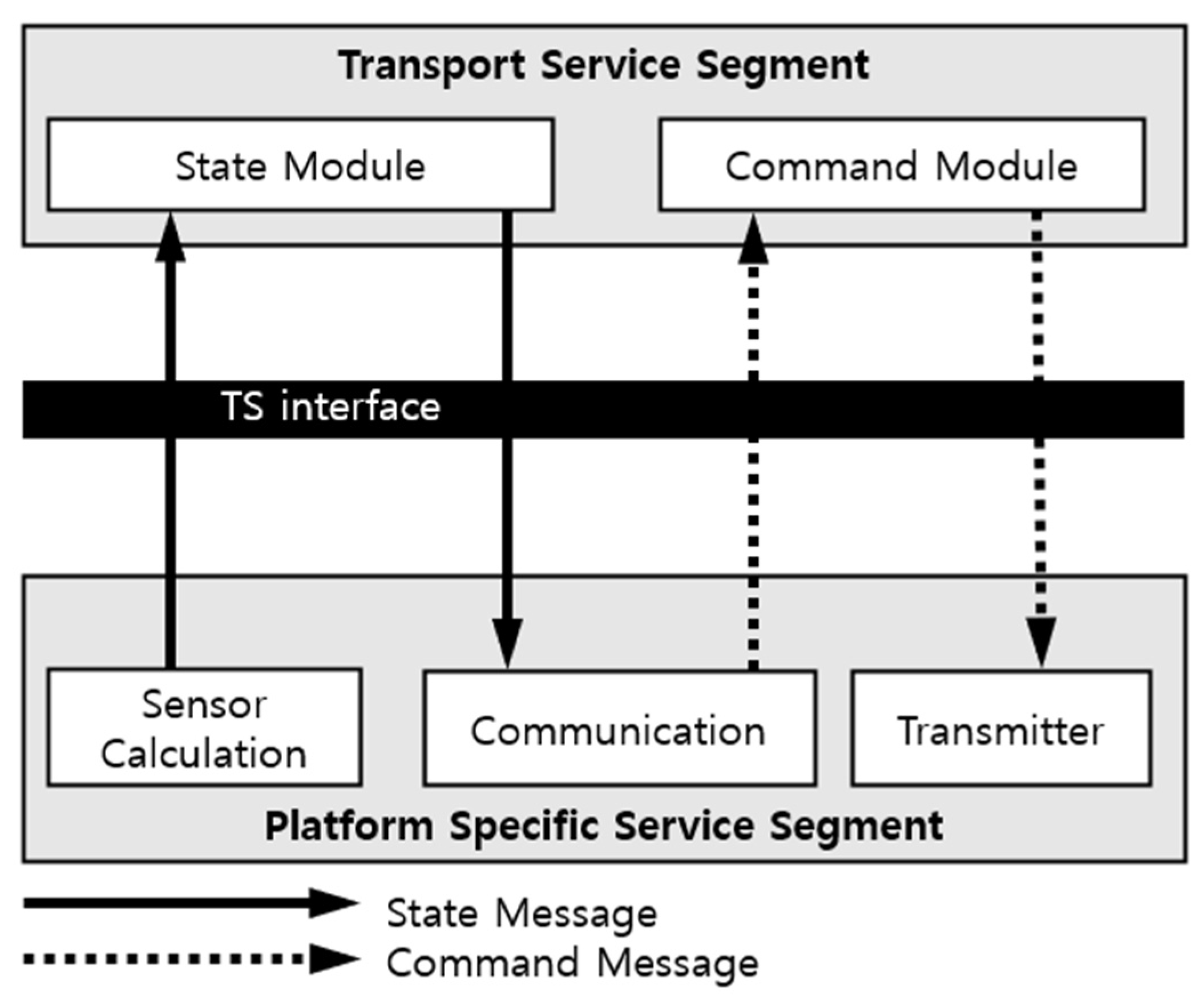
The transport module in the Transport Service Segment (TSS) can transfer data between PSSS and the Portable Components Segment (PCS).
Figure 8 shows the data flow between TSS and PSSS. The transport module consists of two submodules which are StateModule and CommandModule.
The StateModule receives a state message from the main flight module and transfers it to the communication module in the PSSS. Additionally, it receives sensor data from the sensor-calculation module. At the same time, the CommandModule receives command data from the communication module, and it checks data and transfers data to the specific module in the main flight module depending on the message-id. Besides, it receives a message from the main flight module and transfers a message to the transmitter module in the PSSS. All data between PSSS, TSS, and PCS are transferred through the FACE TS interfaces.
5.5. Portable Component Segment
The Portable Component Segment, designed at the top of the software structure, is the key to realizing the UAV flight control function. The main functions, such as UAV flight status management, navigation, and control management, sensor and servo management, and peripheral device management are achieved at this segment, and it consists of five modules: flight control, altitude, position, servo-motor, and main control modules. The modules in the PCS receive and send data from/to TSS via the TS interface.
Main control module: The main control module in the PCS is responsible for controlling the UAV, managing, and showing the vehicle’s current state.
Flight control module: is responsible for changing its flight modes and converting the user’s input into a lean angle, rotation rate, climb rate, etc., that is appropriate for this flight mode.
Attitude control module: calculates attitude and target roll, pitch, yaw rotation rates, converts to high-level motor requests.
Position control module: calculates path and the position, velocity, and acceleration, and updates position.
Servo-motor control module: receives high-level motor request data from modules in the PCS and converts it into individual motor outputs.
6. Implementing the mpFCS
This section explains the implementation steps of the
mpFCS stated in
Section 5. First, we explain how we implement the structure, and then we continue with verification of the implementation.
To implement modules, we analyzed various types of existing software for UAVs with different layers and modules. We choose ArduCopter, part of ArduPilot flight control software suites, an advanced open-source software autopilot system for multicopters, helicopters, and other rotors vehicles. Internal functionalities of our implementation are based on the open source, flight control software ArduCopter [
18].
ArduCopter consists of different layers, and it provides libraries that are responsible for its flight, device drivers, and communication. For example, GCS_Copter and GCS_MAVLink in the application layer are responsible for sending a state message to the communication module and receiving a command message. GCS_MAVLink in the shared library provides a possibility to send and receive messages between GCS and UAV, and it uses MAVLink protocol on its communication. The hardware abstraction layer provides interfaces for various devices, including sensors, boards, etc. The flight codes in the application layer provide possibilities for UAV’s control and management of its movement.
The FACE architecture provides its requirement for each segment and interfaces between segments. To meet the requirements, we follow the matching process described in
Section 5. This process provides the matching table of the software with FACE segments.
Table 4 shows the codes of ArduCopter and our matching of the software with the FACE segments. We matched the basic modules of the ArduCopter into the proposed structure. PCS consists of five modules (flight mode, position, attitude, motor, and main control) that are the main modules of the ArduCopter. In the PSSS, we choose the most basic modules related to the data of IOSS, which are communication, sensor, and transmitter modules.
6.1. Implementation of the Portable Modules
We implemented the structure with modules that consist of portable component segments (PCS), transport services segment (TSS), platform-specific services segments (PSSS), an input-output services segment (IOSS), and the core functions of each segment, which are responsible for sending and receiving a message.
In order to implement the structure with the FACE segment, we performed the following steps:
Identify code dependency and its coupling with different functions in other modules.
Match libraries and modules with the FACE segments.
Match its proprietary interface with FACE interfaces.
Mapping FACE IDL interface files into C++.
We implemented each segment and interface based on the reference implementation guide for FACE architecture [
35].
To implement modules, we divided messages between modules into two main categories: internal and external messages. First, the external message is related to GCS, which can be a raw command message sent by GCS (a message from bottom modules to upper modules) to UAV or a UAV real state message sent to GCS (a message from top modules to bottom modules). Second, the internal message is related to the sensors and motors, which can be a real command message that goes to the UAV motor and actuator (a message from top modules to bottom modules) or a raw state message from the sensor, which needs to be calculated (a message from bottom modules to upper modules).
In order to send and receive the internal and the external message, we implemented the following interfaces:
For implementing the structure, this paper uses Ubuntu Linux 16.04 64-bit operating system and GCC v7.5.0 as compiler and linker.
6.2. Verification
To prove our implementation works faultlessly and messages between modules and GCS are correct, we traced, collected, and compared the mpFCS and the general FCS data. We tested the following test case: (1) external message test (a message to/from GCS), (2) internal message test (a message to/from motor/sensor). A state message on GCS must be equal to the state data that the main flight module sends, and a command message on the flight module must equal a message that GCS sends.
To check and compare the specification of portable modules, we run both the general software and the
mpFCS in the simulated environment.
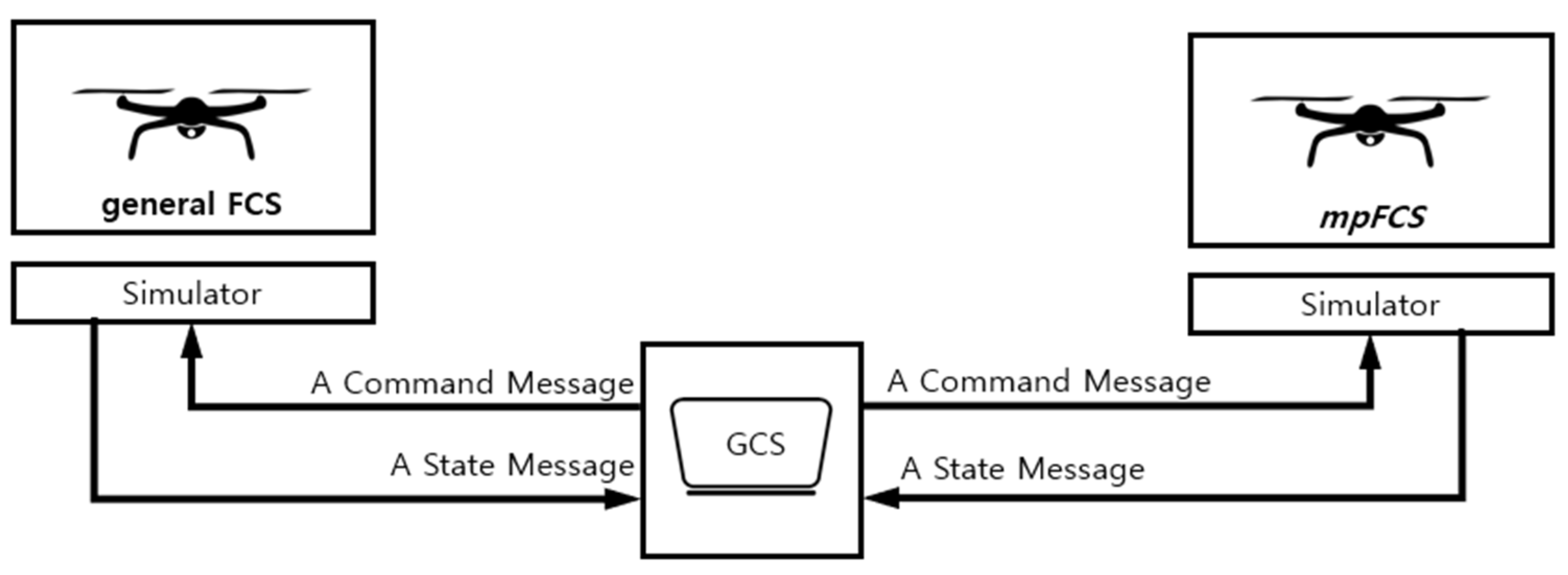
Figure 9 shows the process of comparing the general software and the
mpFCS in the simulation environment. The simulation environment allows the software to run on the PC without any special hardware. The
mpFCS runs on the simulation environment, which runs on the system with Intel i5-10400F 2.9 GHz CPU and 12 GB main memory, and Ubuntu 16.04 LTS-64bit OS. On the other hand, we run the GCS on the second system with Intel i5-4590 3.3 GHz CPU and 8 GB main memory, and Ubuntu 16.04 LTS-64bit OS to control and exchange data between GCS and the
mpFCS. The
mpFCS connects to GCS via TCP. Simultaneously, we run the general FCS in the simulation environment and connect it to GCS on another system with the exact specification. When communications are established, we make the test for sending and receiving data. GCS sends a command message to both simulators and receives a state message from both simulators.
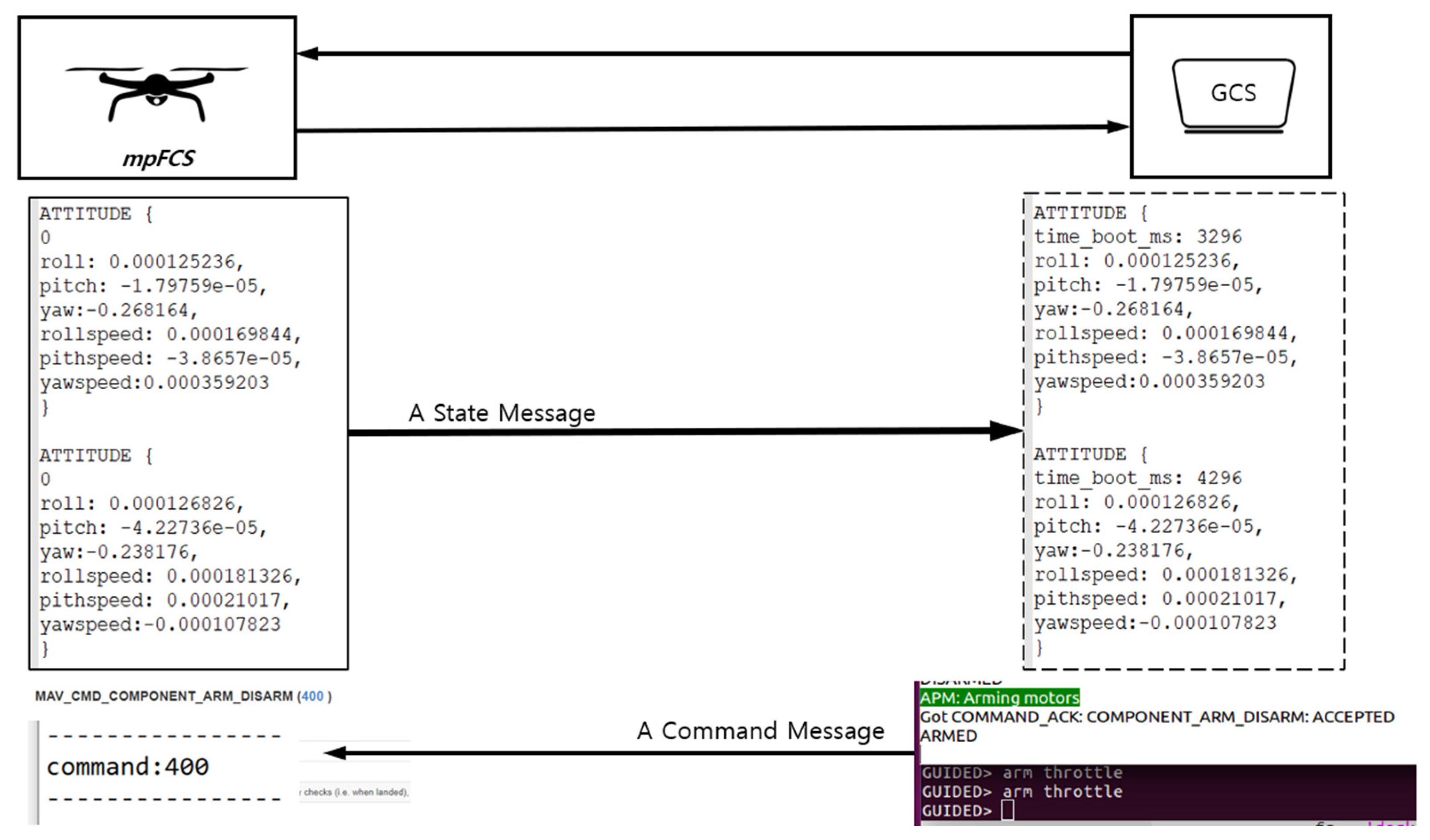
To verify the external message, first, we traced a state message on the communication module and GCS. A test result of the state and command message through its communication modules is shown in
Figure 10. During the flight, the communication module of the software encodes a state message and sends it to GCS. When GCS receives a state message, we compare this message to a message on the communication module. Concurrently, we send a command message to the software. Same as previous steps, when the software receives a command message, we compare this message to a message that we send to the software. The result shows that our solution works appropriately, and its final data between GCS and the simulator are precisely the same.
To verify the internal message, we traced the internal state and command messages between modules. First, we trace the state message from the sensor to the main flight module on both software. During the flight, the sensor module of the software gets a state message and transfers it to the application layer. Second, we traced the command messages among modules. When the main flight module receives a command message, it transfers a message to the motor and actuator. We compare the input and output of each module. The result proves that the
mpFCS works correctly, and its final data among modules are correct. The comparison of data flow between the
mpFCS and general software is shown in
Table 5. This comparison shows that FligtControl from the general FCS depends on the motor, sensor, and communication module and is coupled with them. On the other hand, modules in the PCS of
mpFCS depend only on modules of the TSS.
7. Experiments
This section discusses the experiment and its result. To evaluate modules, we made two experiments as (1) A test of the FACE conformance test suite (CTS) [
36], for verifying conformance of modules to the FACE standard and testing its interoperability with FACE software and its module portability, (2) a test of adding a new module to the structure, for proving extendibility of the software with different modules from FACE software and other software, (3) a test of running the
mpFCS on the Windows system, for verifying portability of the
mpFCS.
Table 6 shows our experiment environments. In order to perform experiments, we use two systems for the environments of UAV simulation and GCS, which have the same software installed on them.
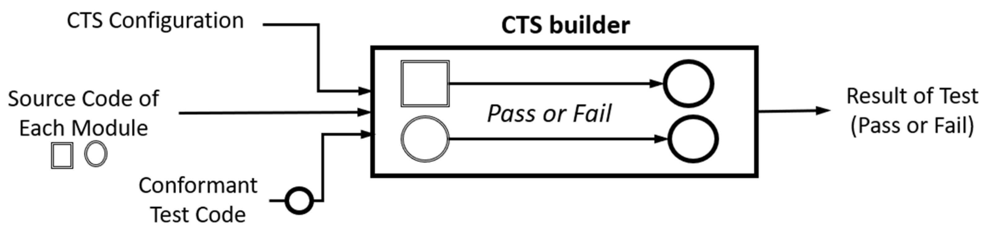
7.1. The FACE Conformance Test Suite Test
The FACE CTS is a testing suite for checking the FACE standard requirements of units in the FACE segments. It provides the testing environment for the FACE standard conformance, and it can test the comfortability of the FACE segments and their interfaces with the FACE software. The software module must be linked with FACE test interfaces and interfaces to run the test most likely linked against FACE test applications provided by the FACE CTS. If the compiling and linking of the software pass the test, the software code is conformant concerning the requirements tested. If the test result fails, the software is not conformant with the FACE, and the software cannot provide portability to the software. Results that test output will show in the browser.
We tested our modules with the FACE CTS, which can test PCS, PSSS, TSS, IOSS, and interfaces. We run the test on the Linux-based computer system, which can also be Windows. After configuring testing environments, we test each segment with the interfaces. To test modules, we made the following steps and configurations.
Create an object file of each module using the makefile,
Link the FACE CTS library to the object file of each module,
Configure the general settings for the testing environment and specific segment settings on the FACE CTS GUI.
Figure 11 shows how the FACE CTS works and its flow. After following the above steps and configuration, we compile and link each segment with the FACE CTS. The module successfully passed the FACE architecture comfortability test. The process of compiling and linking passed the test, and the test output shows detailed information.
Table 7 shows the test results of each module, its interface, and its data in the environment. Each module passed FACE CTS, and the test result on FACE CTS shows that portable modules can be interoperable with the FACE software.
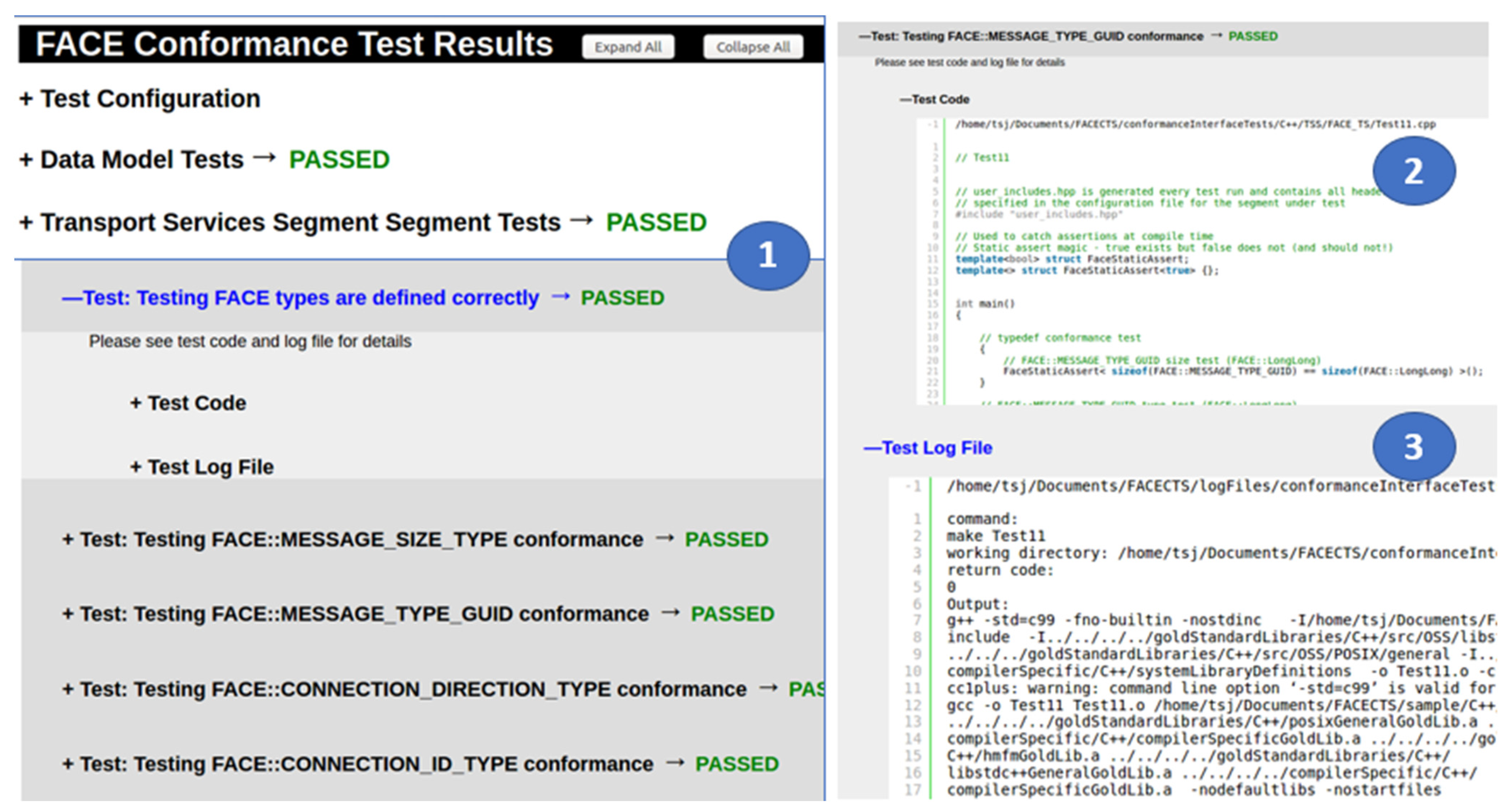
Figure 12 shows the test result of FACE CTS. The test result includes passed or failed for each test. The result also includes the code used for the test and the log generated in performing the test. All results are shown on the web browser after the successful test.
7.2. Adding a Module into the mpFCS
The software’s expandability is the ability that increases the software’s functionality by adding or porting new modules. The module extends the software by adding new functionality or modifying existing functionality, and it must extend the software without ever modifying the core base code. Since we focused on the expandability of the software, we adhere the standard architecture and exploit its interfaces on the mpFCS; thus, the mpFCS can expand with any module that uses the same interfaces. In order to port a new module in the PCS, a module needs to use the TS-Interface. Additionally, modules in the PSSS must use TS-Interfaces and IO-Interfaces. Thus, to prove this, we developed a sample module, ported it into the software based on the proposed structure, and extended it to show its expandability. Additionally, we added a module from the existing software and showed how to add the existing module into the structure.
7.2.1. Adding a New Module into the mpFCS
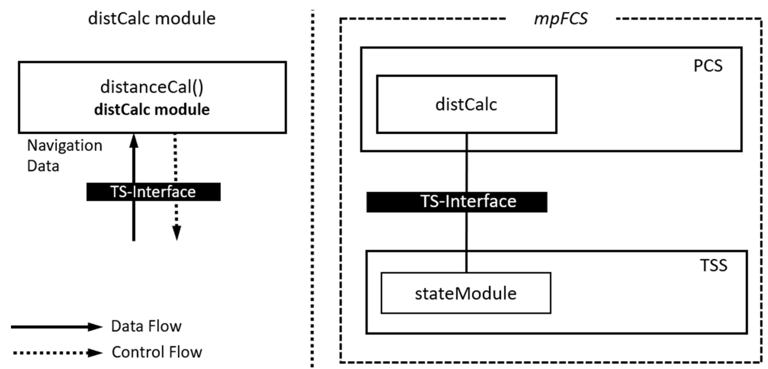
A sample module named distCalc module receives the current navigation data, and it calculates and shows the percentage of the distance between the endpoint and the UAV.
Figure 13 shows the general design of the module and its interface to the transport module. In order to work as a portable module, we located the module in the PCS. To port the module into the software and receive navigation data from the transport module, it must use the TS interface. Thus, we added distanceCal in the distCalc module, and it invokes FACE::TS::Send_Message from the stateModule in the transport module to receive a message. The module receives data from the transport module in every set of time intervals and calculates the distance.
Table 8 shows the specification of the module and sample data collected during its running. To execute and port the module, first, we run the
mpFCS in the simulated environment. When the software runs, the distCalc receives data and calculates it. At first, the module receives the coordination of the starting point that is
(
—the starting point, x—longitude, y—latitude) and endpoint data:
(
—the endpoint) from TSS. Then, the module calculates the distance between two points. Second, the module calculates and shows the percentage between the endpoint and the current location when the UAV moves. In order to calculate this, the module collects the current navigation data that is a new starting point data
, which changes in a set of time intervals from TSS.
After developing the module, we tested it on the FACE CTS. To test a module, we followed the steps mentioned in the FACE CTS test. The distCalc module must pass the test of the TS interface, and its data must be portable with the FACE standard. The module passed the conformance test, and its result is shown in
Table 9.
Same as adding distCalc into the structure, the mpFCS can expand with any different modules that use the standard FACE interfaces.
7.2.2. Adding an Existing Module into mpFCS
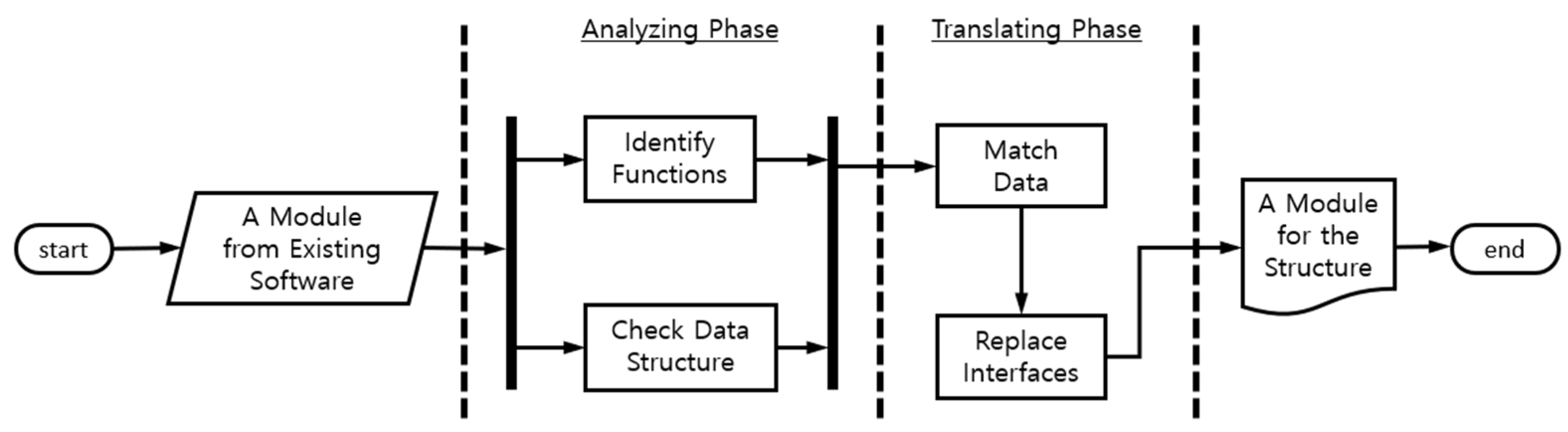
The
mpFCS can be expanded by adding a module from existing software. In order to add an existing software module to the structure, its proprietary interfaces must be replaced with the FACE interfaces. However, due to different data structures and functions, this process requires manual work for each module. Thus, we created a manual process named Interface and Data Translator, which analyzes a module from existing software and provides it for the
mpFCS.
Figure 14 shows a flow of the process. This process consists of two phases: (1) analyzing phase, which analyzes the module from the existing software, and (2) translating phase that replaces interfaces and changes data structure. The result of this process can provide a new module for the structure from the existing software. We followed the above process, converted the module to the
mpFCS, and added the module into the structure.
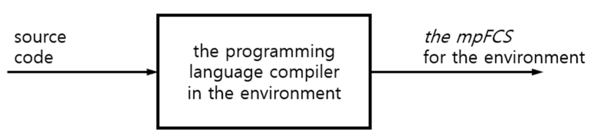
7.3. Running the mpFCS in a Different Environment
Since our approach follows the standard FACE architecture and its interfaces along with programming interfaces, the compiler guarantees portability. It also allows the implemented structure to run on different environments seamlessly. The process of deploying of a FACE-compatible software to any environment is shown in the
Figure 15.
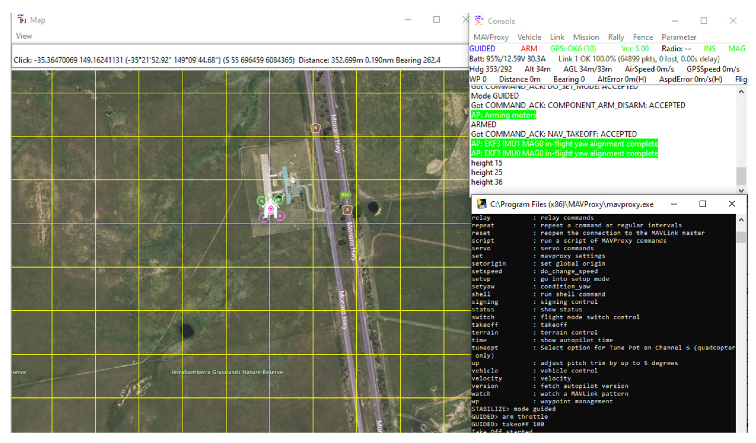
We implemented the mpFCS in Ubuntu Linux 16.04 64-bit operating system. To verify the portability of the mpFCS, we recompile and deploy the mpFCS on a Windows system that has the same hardware specifications we used in our experiments.
Figure 16 illustrates the running of the mpFCS on a Windows system without any issues. Additionally, the distCalc module is successfully ported into the mpFCS that runs on the Windows system. The distCal module works correctly, and its data is the same as on the Ubuntu system. We only present the result acquired in Linux system because the results are the same on both environments.
7.4. Analysis
This subsection discusses a comparison of the mpFCS and the existing flight control software on their module level. This comparison is based on its expandability, interoperability, and portability.
In order to make software portable, expandable, and interoperable, we need to use standard interfaces. Thus, we use the standard interfaces in each module of segments to send and receive a message between them. In the experimentation, a new module uses the TS interface to receive a message from the transport module in TSSS.
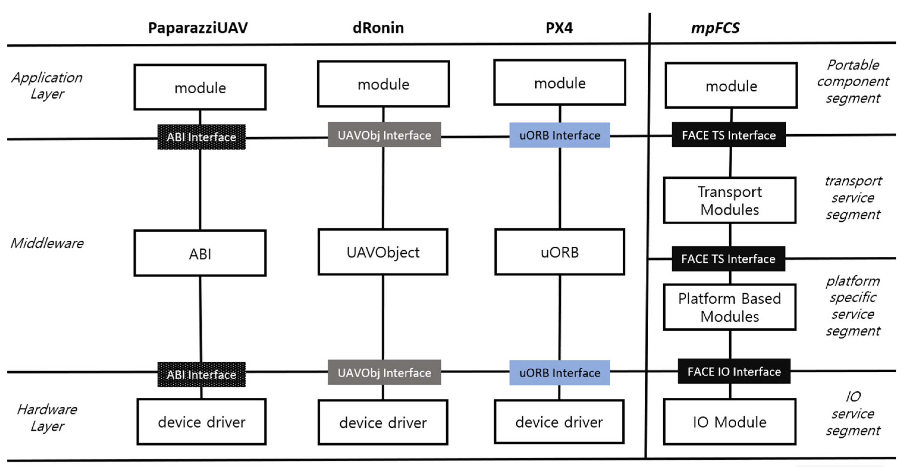
7.4.1. Analysis of Portability
Figure 17 compares layers and interfaces between the existing software and our structure experimentation. The existing software uses its proprietary interfaces for its internal communication to transfer data between modules. PaparazziUAV uses functions from the ABI middleware, which has prefixes such as abiSendMsg and abiBindMsg depending on the message types. dRonin also uses proprietary UAVObj interfaces, and depending on message types, different interfaces of UAVObj are used for transferring messages. uORB messaging API is used in PX4 for internal communication. On the other hand, the
mpFCS uses the FACE standard interfaces in its modules, such as IO interfaces (FACE::IO::Write() and FACE::IO::Read()) and TS interfaces (FACE::TS::Send_Message() and FACE::TS::Receive_Message()) to transfer data between its modules. It brings portability not only to software, but also to the software modules.
7.4.2. Analysis of Expandability
Expandability allows the addition of new capabilities or functionality to the software. The existing software uses its interfaces defined by the software. To expand the software with a user-defined module, the developer needs to understand the structure of the software. To add a new module to PX4 [
19], the developer needs to know how its middleware uORB works and its data structure. However, a module works only on the chosen software. Expanding the software with another module from different software takes time, and a large amount of work is required to modify its source code to expand the software with that module. We expand our structure with a user-defined module named distCalc that calculates the distance between the current point and endpoint. The distCalc can expand any other software that runs in the same environment. On the other hand, the
mpFCS can be expanded by different modules from different FACE software because of the same interfaces. In order to expand the
mpFCS by adding a module from existing software, we created a manual process named Interface and Data Translator, as shown in
Figure 14.
7.4.3. Analysis of Interoperability
Interoperability allows the capability of two or more functional units to process data cooperatively. A new user-defined module needs to interoperate with other modules of the software. Same as expandability, interoperability with other modules from different software requires lots of modification on the software’s source code. A new module, distCalc, expands the mpFCS and uses the FACE standard interfaces (FACE::TS::Receive_Message) to interoperate stateModule in the Transport Service Segment (TSSS). The current capability of the distCalc is only receiving data from TSSS, but capability can increase by sending data to TSS. Due to the FACE interfaces in a new module, the module can interoperate with any software that runs on the FACE environment.
We compared the interfaces, expandability, interoperability, and portability of
mpFCS with other software, and
Table 10 shows the comparison result. The existing software [
2,
6,
7,
8,
9,
10,
11,
12,
13,
14,
15,
16,
17,
18,
19] is not portable, and its modules are tightly coupled due to its unique interfaces. Expanding the existing software with a new module requires understanding its structure and interfaces. However, a new module only expands the chosen software and interoperates its modules.
The experiment result shows that each module of the
mpFCS can be ported to other FACE software, which means modules can be ported to any software that runs on the FACE software environment. After porting a module to another software, it can exchange data with them, which means it is interoperable with another software. Compared with the related work (
Table 10), our structure not only provides portability for its module but also provides the expandability of the software and interoperability with different software.
7.5. Discussion
The verification result shows that the mpFCS works correctly, and experiments show it can provide portability for its software modules to run in the standard FACE environment. Furthermore, experiment results show that it can interoperate with other FACE software and expand with new modules that use FACE interfaces.
Currently, we designed and implemented only the basic modules of the software, but these modules are enough to control the UAV by sending/receiving a message to/from GCS. Additionally, other payloads in the message or an increase of commands will not affect the structure. Since we use the FACE architecture in our solution, more work would be required to port the module with different software types that run in a different environment.


