Article

Evaluation of Series and Parallel Hybrid Propulsion Systems for UAVs Implementing Distributed Propulsion Architectures

1
Aeronautics and Applied Thermofluids Research Group, Department of Mechanical Engineering, Escuela Politécnica Nacional, Quito 170517, Ecuador
2
Department of Electronic Engineering, Escuela Politécnica Nacional, Quito 170517, Ecuador
*
Author to whom correspondence should be addressed.
Aerospace 2022, 9(2), 63; https://doi.org/10.3390/aerospace9020063
Submission received: 19 October 2021 / Revised: 4 January 2022 / Accepted: 18 January 2022 / Published: 25 January 2022
(This article belongs to the Section Aeronautics)

Abstract

:
Current environmental policies for the aviation sector motivate the use of cleaner propulsion alternatives in order to reduce their CO2 footprint and noise pollution in the coming years. In this context, hybrid propulsion systems have emerged as a potential solution, as they have demonstrated a good trade-off between performance and low pollutant emissions. The present work carries out a comparison between parallel and series hybrid propulsion systems using heterogeneous and homogeneous distributed propulsion architectures. In order to highlight the opportunities of distributed propulsion systems and validate the methodology developed, a single propulsion hybrid configuration is used as baseline case for this study. For the propulsion system sizing, this work uses a parametric modelling tool, which includes a constraint analysis coupled with a weight estimation module to determine suitable configurations for a environmental monitoring mission. The latter module includes semi-empirical correlations to size the electric and mechanical components for each propulsion setup. From the results, it has been found that for the representative case of monitoring in the Galapagos Islands, which requires an endurance of approximate 7 h, the parallel hybrid system using three distributed propulsors presents the best performance features in terms of fuel savings, showing a 34% reduction compared with the baseline case. To summarize, the main contribution of this study lies on the development of a methodology to set potential hybrid distributed propulsion configurations for UAVs aimed for determined monitoring missions.

1. Introduction

During the last decade, Unmanned Aerial Vehicles (UAV) have been used for different civil applications, such as ecosystem monitoring, marine patterns surveillance, and search–rescue missions [1,2], among others. Nevertheless, the growing demand for these aviation sectors has led to an increase in fuel consumption and pollutant gas emissions. In this context, the NASA N+3 goals were proposed in 2011 to reduce the fuel burn, noise, and emission of aircraft by 2035 [3].
New hybrid propulsion technologies are being developed to tackle the above, as they combine the advantages of combustion propulsion systems (high energy density) and the low pollution footprint of electric UAVs [4]. As hybrid systems incorporate many technologies, several design methods are being developed and proposed. In 2010, Hiserote [5] performed an analysis of parallel hybrid-electric propulsion system designs for small UAVs. The study compared three different parallel hybrid-electric system designs, each with three unique battery discharging profiles using a constrained static formulation based on traditional aircraft designs, which shows it is possible to achieve up to 40% fuel saving compared to conventional systems using a clutch configuration. In 2015, Friedrich [6] proposed a design and sizing process for a hybrid-electric propulsion, using experimental data from the ICE and EM linked with PC software packages, which shows that a 210 MTOM single seat prototype aircraft can achieve a fuel saving of 37%. Two years later, Cinar [7] developed a methodology for the sizing and synthesis of hybrid power generation and distribution subsystems using Pacelab and SysArc to create a system architecture design tool to evaluate the impact of different propulsion architectures by changing the characteristics of the subsystem at the aircraft and mission requirements. In 2018, Finger and Braun [8] presented a methodology for sizing hybrid-electric aircraft in series and in parallel using a mission performance analysis that incorporates the degree of hybridization in the constraint analysis. The results showed that series hybrid aircraft will always be outperformed by parallel hybrids, if aerodynamic benefits or other integration benefits are not employed. The same year, Xie [9] presented modeling and control of a parallel hybrid-electric propulsion system for UAVs, dividing the power train into two power trains where an engine model was built to predict the dynamics between throttle request and the resulting output. Subsequently, a rules-based controller was designed to achieve the best fuel consumption by regulating the engine to run around its ideal operating line. In 2019, researchers from Delft University [10] presented a preliminary sizing method suitable for the conceptual design of hybrid-electric aircraft, which uses the power train architecture and the associated propulsion air-frame integration effects by modifying the flight performance. The same year, Rohacs [11] introduced a new methodology for electric and hybrid aircraft, which introduces the analyses of energy fraction of flight mission stages into the conceptual design and the implementation of hybridization factor and power split on the conventional concept design methodology. Due to the lack of available validation data, Finger [12] performed a comparison of the Finger and Delft size models, using a 19-seat commuter as baseline. The results show that the MTOM and energy efficiency using the aforementioned models are predicted with a difference of approximately 2% and 5%. Furthermore, hybrid propulsion systems are easily combined with other new technologies, such as distributed propulsion, which increases the performance of the aircraft [13,14,15]. However, this versatility comes with the complexity of defining the proper hybrid architecture for a determined mission profile (see Figure 1).
As previously described, there are several studies on hybrid power trains, most of them based on predefined hybrid air-frames, focusing their implementation for general aviation. As the selection of which hybrid system is suitable relies heavily on the application, this study centers its analysis on exploring distributed propulsion technologies in hybrid systems for ecosystem monitoring [8,16,17]. The case of study, where there are important synergies for hybrid systems, is the Galapagos Islands. There, previous work has shown the necessity of having high autonomy low pollution aircraft for monitoring [18]. This previous work shows the sizing of a series hybrid propulsion system, using the model proposed, to monitor Galapagos Islands and compare the use of two and four stroke engines for single propulsion systems. The results describe an improvement of fuel consumption compared to conventional propulsion system whilst maintaining a lower MTOM and lower wing span (however higher than conventional platforms). In this context, the objective of this research is to explore the potential benefits of different hybrid-electric propulsion systems integrating homogeneous and heterogeneous distributed propulsion designs to perform monitoring missions in protected environmental areas.

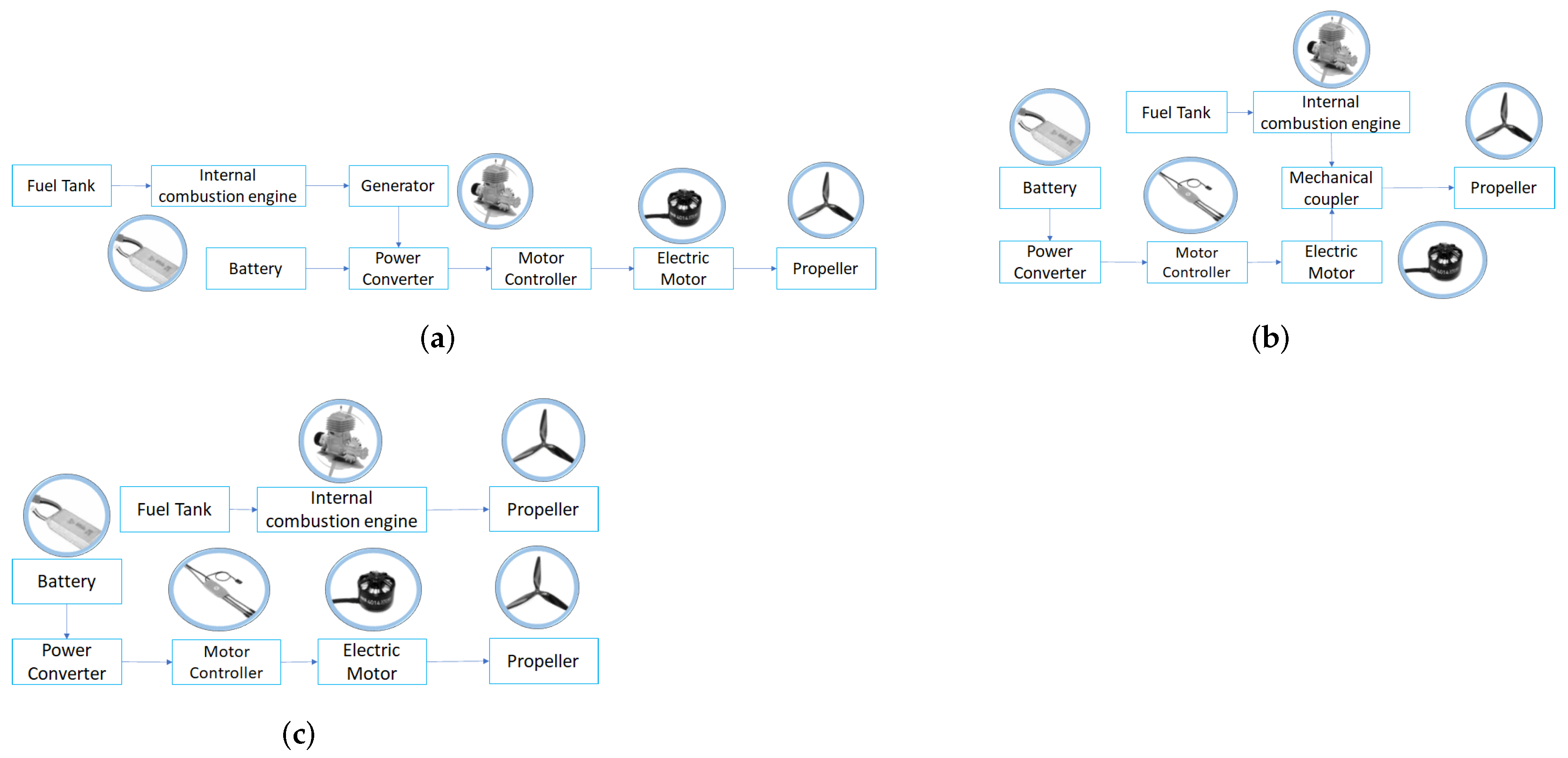
Hybrid Architectures

Series:
In these systems, the electric motor (EM) provides the entire power or thrust required by the UAV. The ICE works as a motor-generator which provides power to the electric propulsion system, as shown in Figure 1a.
Pros:
  • Simplicity of the powertrain control.
  • Lower specific fuel consumption compared to conventional powertrain.
  • Good performance at low flight speeds [19].
  • Optimal operation of the ICE regardless of the operational regime [14].
  • Great synergy with distributed propulsion.
Cons:
  • Higher MTOM due to the use of a generator.
  • Energy losses as the ICE mechanical energy is transformed into electric energy.
  • Higher fuel consumption than parallel powertrain.
Parallel:
These systems add the thrust or power generated by the ICE and the EM to propel the aircraft. Depending on how the power from both sources is managed, it is possible to obtain different configurations, as shown in Figure 1b (Single Propulsion) and Figure 1c (DP).
Pros:
  • Optimal overall propulsion system performance.
  • Full ICE power is available in case of failure of the electric components and regardless of the battery status [15].
  • High energy efficiency in steady conditions [16].
  • Lower fuel consumption than conventional powertrain [8].
  • Great synergy with non homogeneous distributed propulsion [20] (see Figure 1c).
Cons:
  • Complex powertrain controllers.
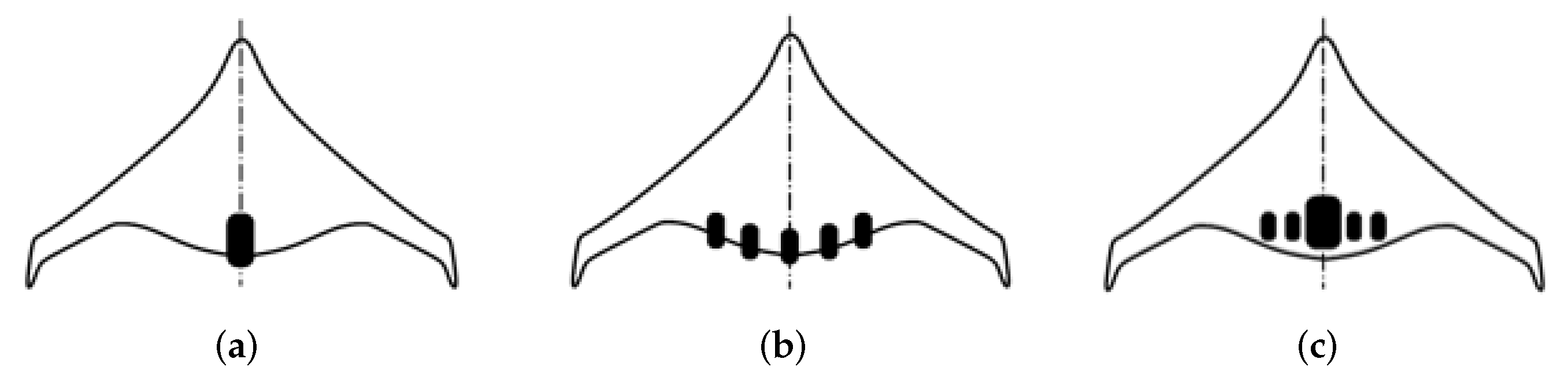
  • In some cases, a mechanical coupler is needed (see Figure 1b).
  • Higher complexity of distributed propulsion implementation than series powertrain.

2. Methodology

The present study focuses on the comparison between series and parallel hybrid propulsion systems for MALE UAV using distributed and single propulsion to perform missions on endangered environmental areas. The case study, or mission, proposed is located on the Galapagos Islands. In each case, the UAV was designed to operate between 600 and 2000 m.a.s.l. and at a maximum cruise velocity of 35 m/s. For the design process, the study uses a constraint analysis coupled with a weight estimation tool to determine the design and hybridization points. The weight estimation tool uses a benchmarking analysis of two engines to size the ICE. The benefits of using each configuration are presented at the end with the optimum configuration of each distributed propulsion case of study and compared with a single propulsion baseline that fulfills the mission requirements. Then, a performance comparison between the parallel and series configurations is performed.

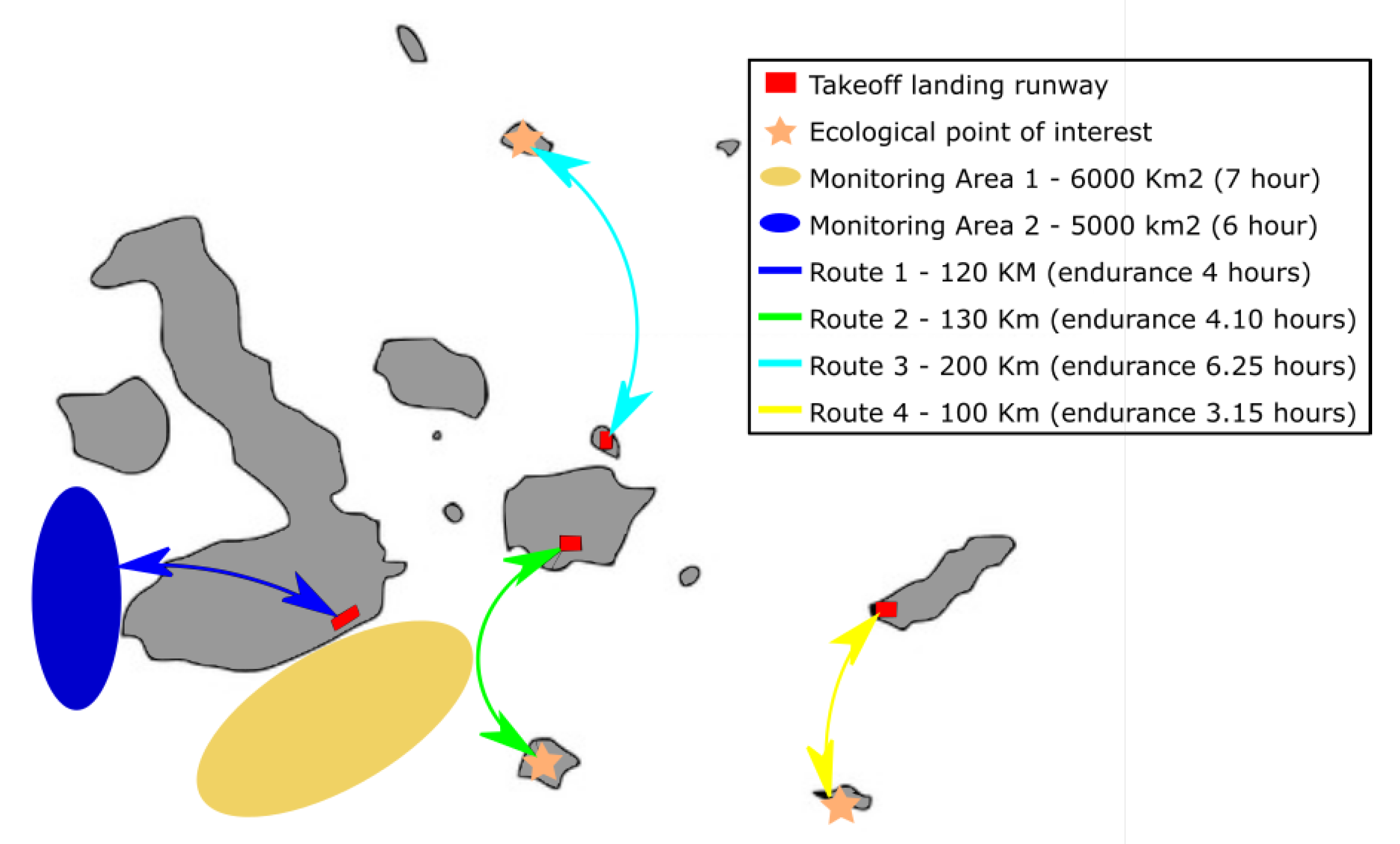
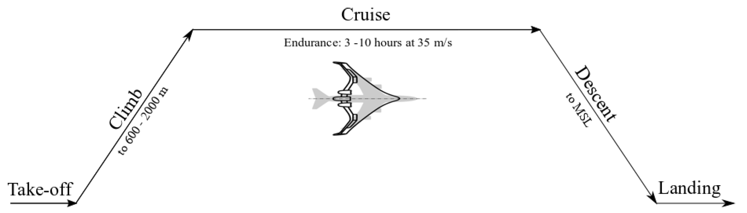
2.1. Design Requirements: Mission Analysis

One of the goals of the study is to determine the suitability of using hybrid propulsion systems to monitor endangered areas. Thereby, a mission on the Galapagos Islands was proposed due to the unique wildlife and flora on the islands. At present, the Galapagos Islands suffer from species invasions, modification of natural habitats, and illegal fishing, in addition to other problems related to tourism [21,22]. For these reasons, authorities have declared that 97% of the territory must be protected, which represents around 133,000 square kilometers. The aforementioned issues have led to the necessity of an eco-friendly monitoring system which can cover a significant area of the Galapagos Islands [23].
The monitoring areas and routes shown in Figure 2 are points of ecological interest, which are considered by this study based on problems in the Galapagos Islands. Based on the latter, the mission profiles need to perform between 3 and 10 h [24,25,26]. In addition, to avoid damaging endemic birds of the zone, the cruise altitude is set between 600 and 2000 m [24,26]. It must be mentioned that the study upper limit of altitude and cruise speed is set based on the resolution of the imagery and radar specifications selected for the mission. A further explanation of the payload components is presented in reference [18]. To summarize, the mission operating requirements are presented in Table 1.

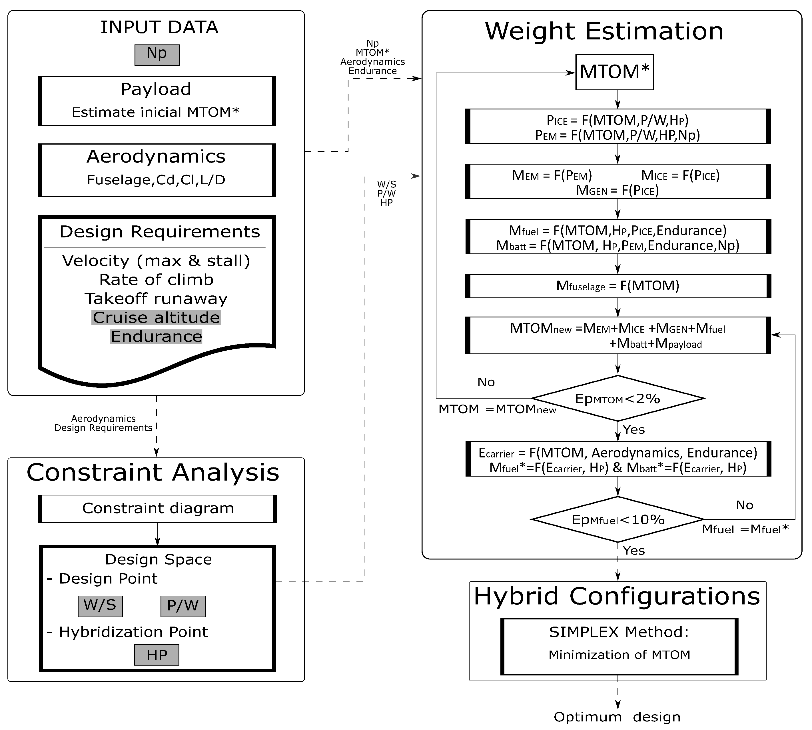
2.2. Framework of Analysis

Figure 3 presents the road map used for the methodology proposed. The methodology combines a conceptual design tool with a weight estimation tool. The first involves a variation of a constraint analysis adapted on hybrid systems to define the design space and hybrid points. The second tool focuses on sizing the different components of the propulsion system using semi-empirical correlations and a benchmarking analysis of commercial engines. Through these two tools, a preliminary propulsion system design is established to assess the performance of the hybrid cycle. As mentioned in a previous work [18], the methodology used the FH approach with some modifications. However, the introduction of hybrid point is not a new concept [8,11]; in the proposed method, the HP is coupled with the number of propellers to split the power require for each system (ICE or EM) and then uses bench marking analysis to calculate the ICE and battery mass, as will be discussed in Section 2.2.2. In addition, the weight estimation module performs a double check of the sized components by calculating the fuel mass not only with the energy required, but also with the power required and endurance in each flight phase and comparing them.
The study uses a blended wing body (BWB) airframe similar to the Boeing X48 model as a BWB design provides advantages in structural, aerodynamic, and operating efficiencies for the aircraft. The baseline airframe, Boeing X48, was sized for a typical 3000 m cruise mission with a maximum take-off mass of 227 Kg, a wingspan of 6.3 m, and wing area of 9.3 square-meters. A graphical representation of the airframe is shown in Figure 4.

2.2.1. Conceptual Design of the Hybrid-Electric UAV
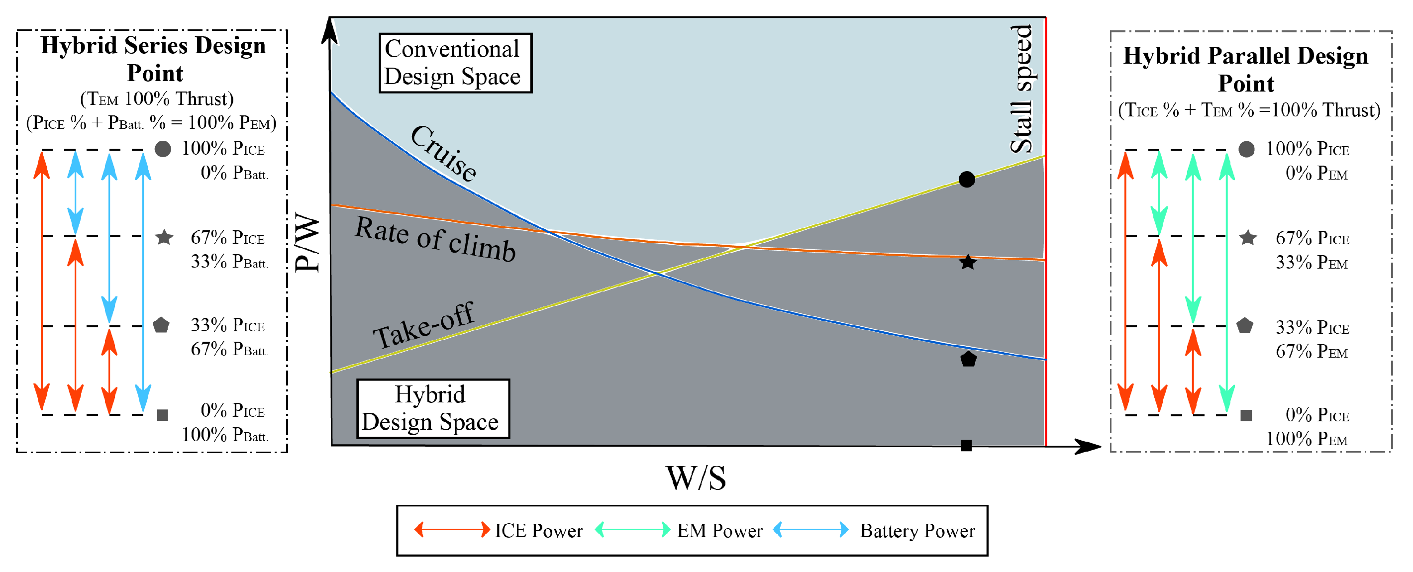
In this stage, preliminary hybrid configurations are obtained using the top level requirements and parametric models. First, a constraint analysis was used to define the design space. Then, the hybridization points were calculated to start the propulsion system sizing. The propulsion system sizing uses a weight analysis with semi-empirical correlations to estimate each element of the system. Subsequently, the most suitable configurations that fulfill the design requirements and initial mass estimation are presented.

Constraint Analysis

The design space was analyzed regarding the power-to-weight ratio (P/W) and wing-loading (W/S). A matching diagram was developed using the top design requirements set presented in Table 2, including stall speed (Vs), cruise speed (Vc), cruise altitude (Hc), rate of climb (ROC), take-off runaway (STO), and some aerodynamic parameters. The study only considered three flight stages for the constraint analysis, the take-off, rate of climb, and the cruise and the mission schema presented in Figure 5. The design constraints used are based on Sadraey [27], where the reader can find the derivations of these equations.

Degree of Hybridization

In this study, the degree of hybridization (Hybrid point) indicates the ratio of the installed conventional propulsion system (ICE power) and the installed maximum propulsion. For hybrid parallel propulsion systems, the maximum installed power is the addition of the electric and the conventional system. On the other hand, for the series hybrid propulsion systems, the EM generates all the power or thrust required by the UAV so the EM power installed is the maximum installed power. Regarding distributed propulsion in both configurations, the study only considers the use of one ICE. Equation (1) is used to obtain the degree of hybridization.
HP = P ICE m a x P m a x
As shown in Figure 6, HP indicates the hybridization point which represents how much P/W supplied by the ICE of the total P/W required. In the case of parallel configurations, the rest of the P/W to fulfill the requirements of each flight stage is supplied by EM. In the case of series configurations, the rest of the P/W to fulfill the energy EM requirements of each flight stage is supplied by the battery pack.

2.2.2. Preliminary Weight Analysis of the Hybrid-Electric UAV

This section presents the considerations used for sizing the different components of the propulsion systems. For this aim, each component is selected, and their technical features are set, with the aim of reducing costs and mass while maintaining a good performance. For all the cases of study, the components sized were the internal combustion engine, fuel tank, battery pack, and electric motor(s). In addition, for series configurations cases, a generator is added, and for parallel configuration cases with single propulsion, a mechanical coupler is added.

Electric motor and Generator

Regarding the efficiency and weight of Brushless out-runner DC electric motors, these were considered to the study. In addition, these electric motors offer a higher torque at low RPM speeds [28]. Hence, EM and generator were sized using semi-empirical models. A wide variety of models for sizing electric motors can be used in this step; the model is presented in Equation (2) [29] and its range of application is between 2 and 300 KW of power.
M EM = a + b · P EM c
where M EM is the EM mass (Kg); P EM is the output EM power required (KW); and a, b, and c stand for coefficients of the power-weight fitting curve with the values of −2.354, 1.609, and 0.6693, respectively.

Battery Package

The electric module controls the flight mission and supplies energy to the electric motor; for that reason, the battery pack has to fulfill both energy requirements [30,31]. Hence, a large number of batteries have been developed for their use in aeronautics, such as Li-Po, Li-ion, LiFePO4, NiCd, and NiMH. Nevertheless, the low energy density of batteries manufactured with current technology constraints the endurance of an aircraft [32]. In contrast, fuel energy density allows to set longer endurance missions by reducing the overall energy carrier UAV weight. In this context, hybrid propulsion systems are used to reduce the battery pack size while increasing the aircraft endurance [33].
However, the battery pack is still an important part of the hybrid propulsion system, as the fuel consumption reduces due to the energy it provides to the propulsion system. Thereby, the battery pack for each configuration was determined using the correlations of Li-Po batteries presented in ref. [34] (see Equation (3)), implementing a 27 series arrange which provides 100 V, and a cell capacity of 2600 mAh with an energy density of 175 Wh/kg.
M C e l l = A · C c e l l B
where M C e l l is the cell mass (g); C C e l l is the cell capacity (Ah) and A and B stand for coefficients for unitary cell weight with the values of 0.0446 and 0.9273, respectively.
M b a t t = # c e l l s · M c e l l
where M b a t is the battery mass and # c e l l s is number of cells.
# c e l l s = E b a t t E c e l l
where M b a t is the battery mass and # c e l l s is the number of cells.

Power Converter

Most of power in aircraft is supplied by internal converters, therefore this research used the power density to estimate the mass of the converter. The power converter employed in this work is a DC–DC converter as batteries and generators were considered to operate with DC power [35].
M p o w e r c o n v e r t e r = 0.17 kg KW E b a t t E c e l l
where M b a t is the battery mass and # c e l l s is the number of cells.

ICE Selection

A wide variety of ICE have been used in aviation over time due to their long endurance operation and high power or thrust generated per fuel mass consumption [29,36]. Nowadays, the most common ICE manufactured and employed in aircraft are piston-prop, turbo-shaft, turboprop, turbofan, turbojet, and ramjet [36,37]. Nevertheless, gas turbines are expensive and do not perform well at low cruise speeds. For these reasons, the study considered the piston-prop engines owing to its easy purchase, low purchase maintenance costs, and easy assembly.
  • ICE performance: In order to obtain more accurate results due to the ICE performance decrease with the increase in the operation altitude, the Gagg and Ferrar equation, which is used for engines driving a constant-speed propeller, was employed to determine the engine’s power fall-off as a function of density [38,39].
  • Benchmarking analysis: The study considered an Otto’s cycle ICE of two strokes. These types of ICE have high power density, low weight, low costs, compact dimensions, high efficiency, and great reliability, which are the key factors in designing and sizing propulsion systems [40]. In this context, the model used to size the propulsion system is based on a semi-empirical model presented in ref. [34] (see Equation (7)) and consists of an empirical correlation based on a database of 114 two stroke engines.
    M ICE = A · P ICE B
    where M ICE is the ICE mass (Kg), P ICE is the output ICE power required (W), and A and B stand for coefficients of ICE engines weight presented in Table 3.

Empty Weight Fraction

The empty weight fraction can be estimated statistically from historical trends. The empty weight can be calculated using the next equation and includes the mechanical transmission.
M e m p t y MTOM = a · MTOM c
where M e m p t y is the empty mass (Kg) and a and c stand for coefficients of empty weight fraction with the values of 0.96 and −0.06, respectively [41].

2.2.3. Mission Energy Consumption Schedule

The energy carrier can be determined by estimating the energy demand (aerodynamic drag, kinetic energy, and potential energy) from each flight phase. The energy carrier was estimated using Equation (9) and the time and velocity varies depending on the flight phase. For example, in the cruise stage, only aero-drag energy is considered, and the time is equal to the endurance. The study does not consider the energy demand of the taxi phase.
Δ E = MTOM · g · v L D · Δ t Δ E A e r o . D r a g + MTOM · Δ v 2 2 Δ E K i n e t i c + MTOM · g · R o C · Δ t Δ E P o t e n t i a l

Fuel Consumption

The fuel consumption is obtained using the energy carrier, hybrid point, and specific fuel consumption (SFC) for each flight phase and then compared with the fuel obtained by the power required, time, hybrid point, and SFC in each phase to check the results.
M f u e l = E · HP · SFC
M f u e l * = P ICE · Δ t · SFC

2.2.4. Propulsion Schemes

The study considered the use of one and three propellers for each hybrid configuration. For this aim, two distributed propulsion hybrid configurations (series and parallel) are proposed using the single propulsion hybrid configuration as baseline, see Figure 7a. Moreover, the study used homogeneous distributed propulsion (all propellers were the same size) for series hybrid systems, see Figure 7b. The architecture of series systems allows us to divide the thrust equally over small propellers because the ICE only operates as a generator. On the other hand, parallel systems use heterogeneous distributed propulsion (a central propeller of a different size to the lateral propellers, which are the same size), see Figure 7c, where the ICE drives the main propeller while the electric motors drive the secondary propellers.

3. Results and Discussion

In this section, the distributed propulsion hybrid configurations are studied using the single propulsion hybrid configuration as baseline. Furthermore, a comparison between series and parallel hybrid systems with homogeneous and heterogeneous distributed propulsion, respectively, is analyzed to determine the suitability of implementing hybrid systems in environmental monitoring missions. Each configuration presented is defined to fulfill a monitoring mission for applications at different altitudes (600 m and 2000 m).

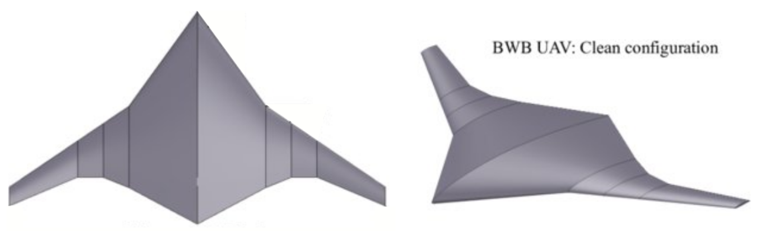
3.1. Baseline Reference Model

The methodology proposed in reference [8] is used to verify the model employed to size hybrid propulsion systems on this research. The FH Aachen method has been used for several studies [15,42] and sensitivity studies [12]. The mission specification and top-level design requirements for the validation are shown in Table 4.
Table 5 shows the comparison of the sized aircraft using the proposed and FH Aachen methods. The agreement between the two methods is good; nevertheless, some variations are possible as the sizing models of the different components are not the same. The higher variation is the observed in the internal combustion engine mass, as the proposed method considers the ICE performance decrease due to operation altitude. The difference in MTOM and fuel mass are less than 4% and 8%, respectively.
Hybridization of mid-scale aircraft is not a new concept; nevertheless, to date, only a few prototypes have been built using this innovative technology. This research employs the parallel hybrid HEPA Geamex Soul developed by Cambridge University [6,43] and the DA-36 E Star series hybrid aircraft design by Siemens and EADS [44,45] to compare the proposed sizing method with real hybrid aircraft in addition to previews validation. Table 6, the comparison of the proposed model to sized real aircraft, reveals a good agreement on the design point and MTOM between real data and data obtained with the model. Furthermore, the hybridization point presents the highest variation, which implies a greater variation of the propulsion system. However, is important to note that the aircraft used in this section employs a baseline air-frame which limits the propulsion system design as it is not possible to alter the air-frame, while the proposed model does not present this limitation.

3.2. Constraint Analysis

In Figure 8, the design space for each configuration is depicted for the proposed operation altitudes of 600 and 2000 m. In addition, the cruise velocity for each operating altitude is set for the case of minimum drag and corresponds to 32 and 35 m/s for 600 and 2000 m, respectively. The figure shows the effects of the operating conditions and constraints of V s , V c , R O C , and S T O on the design space. As expected, the analysis shows that the operation altitude increases the power required in rate of climb and cruise phases. In addition, the matching diagram is used to obtain the P/W, W/S, and degree of hybridization of each configuration tested. For the sake of clarity, one of the configurations designed in the diagram has been included.
Figure 9 presents the optimal design points of each configuration against the endurance. As expected, the results show that the wing and power loading increase with the duration of endurance missions, which implies a growth of the power and energy demand. Hence, the MTOM increases mainly by the augmentation of battery pack due to its low energy density and the fuel mass. Regarding the number of propellers, the analysis shows that in both parallel and series hybrid configurations with one propeller the design point constantly increases until it reaches the stall speed constraint. On the other hand, by using distributed propulsion with series hybrid configurations, the variation of the design points presents an early increment until it stabilizes on a point near the stall speed constraint. This behavior was found as the methodology used considers the implementation of the battery pack only for take-off and rate of climb flight phases. Thereby, the design point at bigger endurance stabilizes nearer to the stall speed constrain. Owing to fact that ICE can provide the power required during cruise, at higher endurance the UAV starts to work as fuel driven aircraft with an initial electric boost. The same phenomenon occurs in the case of the hybrid parallel configuration with three propellers, which decreases from the maximum and then stabilizes. Moreover, the reduction in hybrid point at higher endurance indicates that the propulsion system needs a bigger EM to the initial boost. The main difference between series and parallel systems with distributed propulsion is how the ICE power is used. As aforementioned, for series systems, the ICE only supplies energy for the electric system, which makes a full fuel driven propulsion system impossible for these configurations with the proposed methodology. As the resolution of the model used to size the EM is not accurate enough for small EMs, which distort the results of parallel hybrid systems with DP, no results before six and five hours for missions at 600 and 2000 m, respectively, will be presented for low endurance missions. In addition, Figure 9a,b exhibit the design points and endurance for the optimal hybrid configurations from the design constrain analysis (lower hybridization points reduces weight of the propulsion system).
Another crucial parameter of the design space to be analyzed is the degree of hybridization, because the size of each component of the propulsion system varies with this variable. Figure 9c,d present the results of hybridization of each configuration. The results show that the degree of hybridization decreases as the endurance demand increases due to the change of the design point. In the case of series hybrid systems, the degree of hybridization presents a similar trend for distributed and single propulsion with small differences, being the hybridization degree for three propellers lower at shorter endurance and higher at longer endurance missions, compared to single propulsion as the variation of the aforementioned design point. The small variation of degree of hybridization between single and distributed propulsion is observed for the reason that the aerodynamic model used in the method is a basic model. Furthermore, single propulsion and distributed series system present an optimal performance with a degree of hybridization of 24.27% at 9 h and 25.32% at 6 h for a mission at 600 m because the design points, W/S, and P/W, are about to reach their upper limits, where MTOM and fuel consumption rate are best. Regarding parallel hybrid systems, distributed propulsion systems present lower degrees of hybridization than single propulsion. As aforementioned, the difference in the trend of the degree of hybridization is due to the considerations of the methodology used of EM and ICE. For DP parallel, the optimal point was selected where the EM model starts to stabilize; as Figure 9c shows, the optimal degree of hybridization is 24.07% at 7.5 h and 600 m mission. Meanwhile, for parallel hybrid architecture with single propulsion, the optimum (27.07%) is reached at 10 hours for the mission at 600 m. In addition, the results show that parallel hybrid configurations have a higher degree of hybridization compared to series configurations at the same endurance, as the series hybrid design point reaches its upper limit sooner.

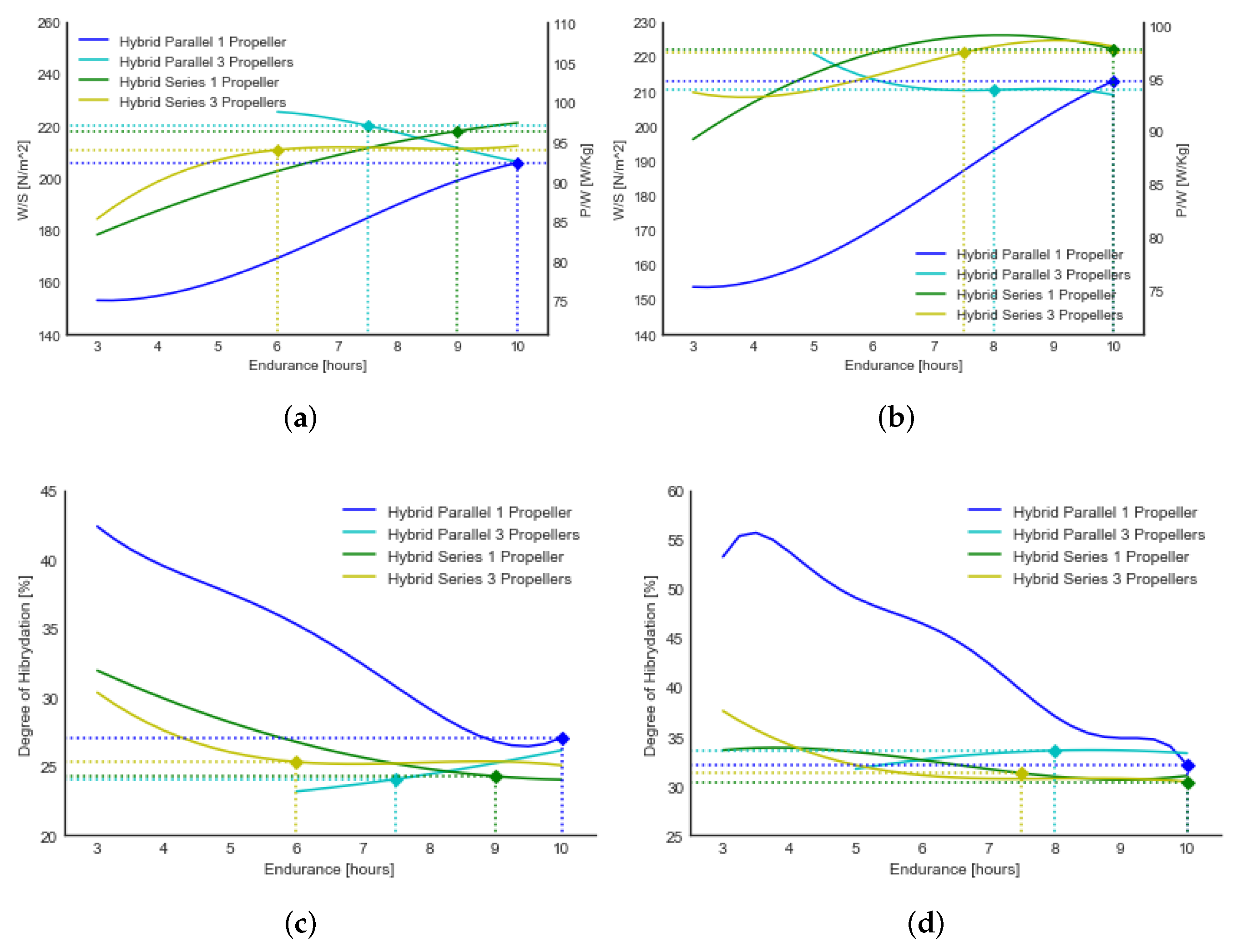
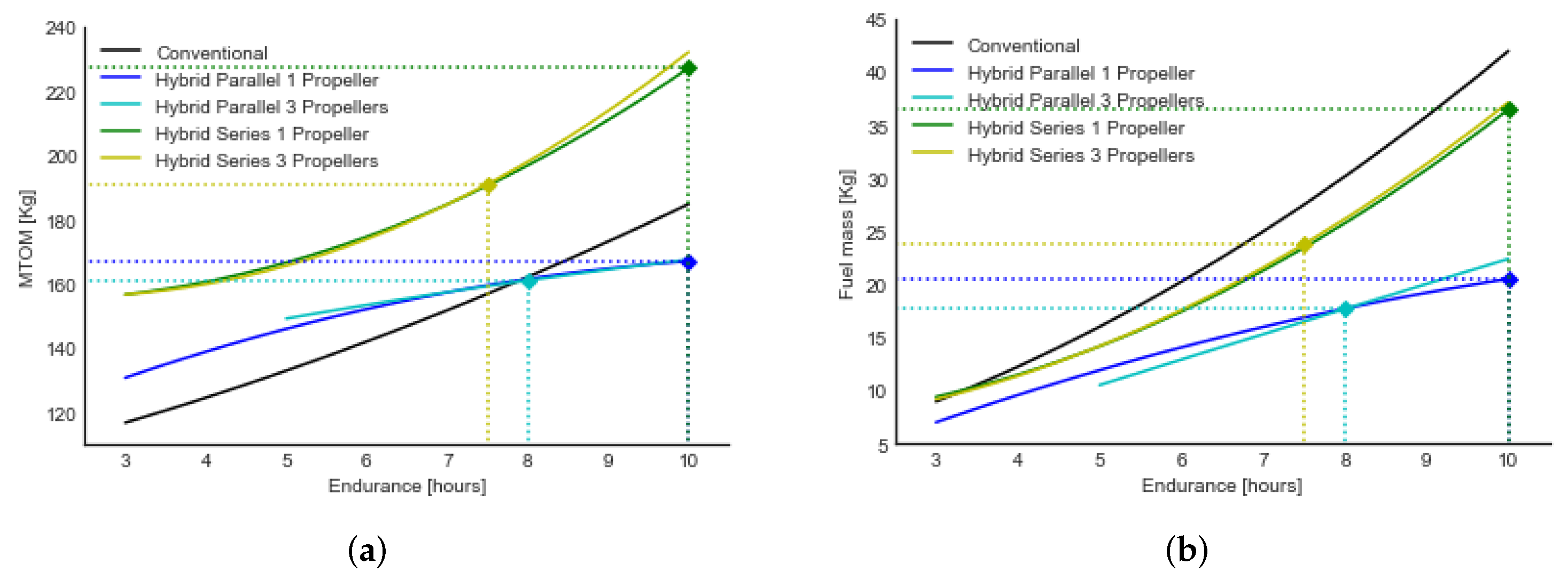
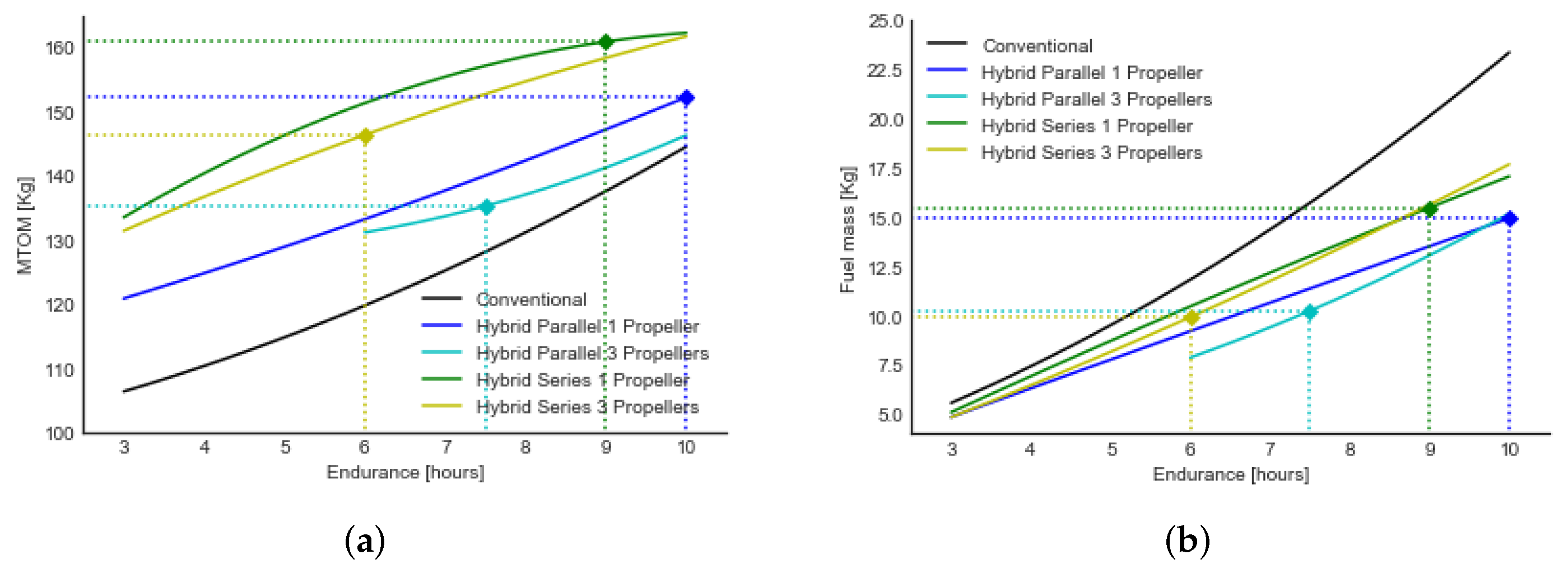
3.3. Hybrid Configurations Performance

This section presents the comparison between parallel, series hybrid propulsion system and conventional propulsion with one and three propellers. The results show that the MTOM is lower in the parallel hybrid configurations compared with the series configurations, as series configurations present higher power loading and need a generator which increases the propulsion system mass. Regarding the fuel consumption, series hybrid configurations have higher fuel consumption than parallel propulsion systems due to the greater need for ICE and lower energy efficiency, due to the transformation of the mechanical energy of the ICE into electrical energy. However, all the featured hybrid powertrains have better fuel performance than conventional ones because, in these configurations, the ICE always operates at its best thermal performance point.
In the case of the 600 m cruise mission (see Figure 10), all hybrid cases present a higher MTOM than the conventional one. For series hybrid configurations, distributed propulsion presents a lower MTOM and fuel consumption than single propulsion, as the degree of hybridization is lower at short endurance, which decreases the size of the ICE and fuel and presents a lower P/W at large endurance which reduces the mass of all propulsion systems. In this context, series hybrid DP presents an optimum configuration, with a fuel saving of 16.12% at six hours endurance, and with single propulsion presents 23.14% fuel saving at 9 h mission compared to conventional powertrains. Regarding parallel hybrid systems, the results show that distributed propulsion configurations perform better than single propulsion for endurance less than 10 h due to the lower degree of hybridization. Near the 10 hour mission, the fuel performance is almost the same because the power loading of both architectures is equal. In this context, the results exhibit that using distributed propulsion with parallel hybrid systems the optimum configuration is at 7.5 h mission with 34.88% fuel saving, and with single propulsion it is possible to reach a fuel saving of 36.03% at 10 h endurance, as the configurations presented before show the best MTOM-fuel consumption benefits.
Moreover, Figure 11 presents the results of the thermal performance for a mission at 2000 m. The analysis shows that the series configurations with one and three propellers present a similar MTOM and fuel consumption, because the power loading and degree of hybridization difference between each configuration is low, which implies the use of a similar ICE at a same endurance. In the case of series propulsion system, an optimal configuration regarding MTOM and fuel consumption is reached at 7.5 h for distributed propulsion system and 10 h for single propulsion with a fuel saving of 13.48% and 13.10% compared to conventional propulsion systems. Regarding parallel configurations, it is possible to see that the trend of MTOM using single and distributed is almost equal after missions of 6 h of endurance, as the point of design of distributed propulsion systems decreases and the degree of hybridization increases near the same value of single propulsion architectures. In addition, comparing the fuel consumption, the parallel distributed propulsion presents a slightly lower fuel requirement for missions before 8 h compared to parallel single propulsion, due to the stabilization of the power loading of distributed parallel configurations. Additionally, an optimum configuration of distributed and single propulsion considering the MTOM and fuel consumption rate are reached at 8 and 10 h, which represents a fuel saving of 41.37% and 51.11% respectively.
To summarize, Table 7 presents the results of the optimal configurations of each architecture. Results at 600 m cruise missions show that series system with one propeller performs better at 9 h with a MTOM 16.91% heavier and fuel saving of 23.14% comparing to conventional aircraft. Furthermore, in the case of series using three propellers, the overall performance is optimum at a 6 h mission which is 22.17% heavier and uses 16.52% less fuel. Regarding parallel architectures, using one propeller presents a better performance above 10 h mission and using three propellers above 7 h, presenting a fuel saving of 36.03% and 34.88% and a increase in MTOM of 5.33% and 5.57%, respectively, compared to fuel driven architectures.

4. Conclusions

In this study, a preliminary sizing tool for hybrid propulsion system is used to compare, in detail, four aircraft concepts featuring novel technologies such as distributed homogeneous and no homogeneous propulsion. The proposed methodology was evaluated comparing referenced FH Aachen methodology with a deviation of approximately 5% regarding power-loading and less than 6% for MTOM. The higher discrepancy was presented in the ICE sizing, as the proposed method considers the ICE performance decrease due to operation altitude.
The proposed method was used to test parallel and series propulsion systems, each with one or three propellers. The results obtained show that the degree of hybridization increases with the operating altitude as the proposed methodology adapted the ICE to its best performance point in cruise.
The results show that series hybrid powertrain is between 20% and 40% heavier than using a conventional powertrain but consumes less fuel for the proposed missions. It is possible to obtain a fuel reduction in between 13% and 24% for single and distributed propulsion.
Furthermore, the implementation of a parallel hybrid powertrain is about 8% heavier than a conventional power train. As the endurance increases, the difference in MTOM decreases. In terms of fuel consumption, parallel configurations have better thermal performance than conventional configurations for short missions. Depending on the mission is possible to achieve between 30% and 50% fuel savings using single propulsion and distributed propulsion. Due to the lack of baseline data from actual hybrid-electric aircraft, it was not possible to validate the results obtained with experimental data, respectively.
Overall, the study showed that hybrid series and parallel MALE UAVs using single and distributed propulsion can be a viable technology for monitoring environmentally protected areas, as they enable significant fuel savings. However, further study involving a more precise aerodynamic analysis is necessary before proceeding with the UAV design, as fuel consumption is directly affected by aircraft performance. In addition, it is essential to determine the best external aerodynamics characteristic for hybrid propulsion systems, such as the design of nacelle, propeller, and shape of wings (morphed wings) that best fit this innovative technology.

Author Contributions

Conceptualization, E.V., E.C. and M.P.; methodology, D.J. and E.V.; investigation, D.J., A.H. and E.C.; data curation, D.J. and A.H.; validation, D.J., E.C. and E.V.; formal analysis, D.J., E.V., M.P. and E.C.; writing—original draft preparation, D.J., A.H. and E.V.; writing—reviewand editing, E.C., M.P. and E.V. All authors have read and agreed to the published version of the manuscript.

Funding

Escuela Politécnica Nacional: Project PIMI 18-01.

Institutional Review Board Statement

Not applicable.

Informed Consent Statement

Not applicable.

Data Availability Statement

Not applicable.

Acknowledgments

The authors gratefully acknowledge the financial support provided by Escuela Politecnica Nacional for the development of the internal project: PIMI 18-01. In addition, the authors thank Cranfield University GCRF networking grant, the Waitt ROC grant 2020 and VLIR-UOS EC2020SIN278A101 project for their support.

Conflicts of Interest

The authors declare no conflict of interest.

Abbreviations

ARAspect Ratio
BWBBlended Wing Body
EMElectric Motor
H C Cruise altitude
HPHybrid point
ICEInternal Combustion Engine
M b a t t Batteries mass
M EM Electric motor mass
M f u s e l a g e Fuselage mass
M f u e l Fuel mass
M GEN Generator mass
M ICE Internal combustion engine mass
MTOMMaximum take-off mass
NpNumber of propellers
P EM Power electric motor
P ICE Power internal combustion engine
P/WPower to weight ratio
ROCRate of climb
SFCSpecific fuel consumption
STOTake-off runaway
S W Wing reference Area
UAVUnmanned Aerial Vehicle
V C Cruise Speed
V S Stall Speed
W/SWing loading

References

  1. Panagiotou, P.; Tsavlidis, I.; Yakinthos, K. Conceptual design of a hybrid solar MALE UAV. Aerosp. Sci. Technol. 2016, 53, 207–219. [Google Scholar] [CrossRef]
  2. Austin, R. Unmanned Aircraft Systems: UAVS Design, Development and Deployment; John Wiley & Sons Ltd.: Chichester, UK, 2011; Volume 54. [Google Scholar]
  3. Ashcraft, S.W.; Padron, A.S.; Pascioni, K.A.; Stout, G.W., Jr.; Huff, D.L. Review of Propulsion Technologies for N+ 3 Subsonic Vehicle Concepts; NASA Glenn Research Center: Cleveland, OH, USA, 2011.
  4. Riboldi, C.E.; Gualdoni, F.; Trainelli, L. Preliminary weight sizing of light pure-electric and hybrid-electric aircraft. Transp. Res. Procedia 2018, 29, 376–389. [Google Scholar] [CrossRef]
  5. Hiserote, R.; Harmon, F. Analysis of hybrid-electric propulsion system designs for small unmanned aircraft systems. In Proceedings of the 8th Annual International Energy Conversion Engineering Conference, Nashville, TN, USA, 25–28 July 2010; p. 6687. [Google Scholar]
  6. Friedrich, C.; Robertson, P.A. Hybrid-electric propulsion for aircraft. J. Aircr. 2015, 52, 176–189. [Google Scholar] [CrossRef]
  7. Cinar, G.; Mavris, D.N.; Emeneth, M.; Schneegans, A.; Riediger, C.; Fefermann, Y.; Isikveren, A. Sizing, integration and performance evaluation of hybrid electric propulsion subsystem architectures. In Proceedings of the 55th AIAA Aerospace Sciences Meeting, Grapevine, TX, USA, 9–13 January 2017; p. 1183. [Google Scholar]
  8. Finger, D.F.; Braun, C.; Bil, C. An initial sizing methodology for hybrid-electric light aircraft. In Proceedings of the 2018 Aviation Technology, Integration, and Operations Conference, Atlanta, GA, USA, 25–29 June 2018; p. 4229. [Google Scholar]
  9. Xie, Y.; Savvaris, A.; Tsourdos, A.; Laycock, J.; Farmer, A. Modelling and control of a hybrid electric propulsion system for unmanned aerial vehicles. In Proceedings of the 2018 IEEE Aerospace Conference, Big Sky, MT, USA, 3–10 March 2018; pp. 1–13. [Google Scholar]
  10. De Vries, R.; Brown, M.; Vos, R. Preliminary sizing method for hybrid-electric distributed-propulsion aircraft. J. Aircr. 2019, 56, 2172–2188. [Google Scholar] [CrossRef]
  11. Rohacs, J.; Rohacs, D. Conceptual design method adapted to electric/hybrid aircraft developments. Int. J. Sustain. Aviat. 2019, 5, 175–189. [Google Scholar] [CrossRef]
  12. Finger, D.F.; de Vries, R.; Vos, R.; Braun, C.; Bil, C. A comparison of hybrid-electric aircraft sizing methods. In Proceedings of the AIAA Scitech 2020 Forum, Orlando, FL, USA, 6–10 January 2020; p. 1006. [Google Scholar]
  13. Bravo, G.M.; Praliyev, N.; Veress, Á. Performance analysis of hybrid electric and distributed propulsion system applied on a light aircraft. Energy 2021, 214, 118823. [Google Scholar] [CrossRef]
  14. Zhao, H.; Burke, A. Modelling and Analysis of Plug-in Series-Parallel Hybrid Medium-Duty Vehicles; ITS UC: Davis, CA, USA, 2015. [Google Scholar]
  15. Finger, D.F.; Braurr, C.; Bil, C. Case studies in initial sizing for hybrid-electric general aviation aircraft. In Proceedings of the 2018 AIAA/IEEE Electric Aircraft Technologies Symposium (EATS), Cincinnati, OH, USA, 12–14 July 2018; pp. 1–22. [Google Scholar]
  16. Hung, J.; Gonzalez, L.F. On parallel hybrid-electric propulsion system for unmanned aerial vehicles. Prog. Aerosp. Sci. 2012, 51, 1–17. [Google Scholar] [CrossRef] [Green Version]
  17. Olsen, J.; Page, J.R. Hybrid powertrain for light aircraft. Int. J. Sustain. Aviat. 15 2014, 1, 85–102. [Google Scholar] [CrossRef]
  18. Valencia, E.A.; Jimenez, D.; Alulema, V.H.; Roumeliotis, I.; Montalvan, J.; Pozo, M.; Cando, E. Modeling of a series hybrid propulsion UAV used for monitoring in the Galapagos Islands. In Proceedings of the AIAA Propulsion and Energy 2020 Forum, virtual event, 24–28 August 2020; p. 3960. [Google Scholar]
  19. Friedrich, C.; Robertson, P.A. Design of hybrid-electric propulsion systems for light aircraft. In Proceedings of the 14th AIAA Aviation Technology, Integration, and Operations Conference, Atlanta, GA, USA, 16–20 June 2014; p. 3008. [Google Scholar]
  20. Kim, H.D. Distributed propulsion vehicles. In Proceedings of the 27th International Congress of the Aeronautical Sciences, Nice, France, 19–24 September 2010; pp. 2010–2011. [Google Scholar]
  21. Carr, L.A.; Stier, A.C.; Fietz, K.; Montero, I.; Gallagher, A.J.; Bruno, J.F. Illegal shark fishing in the Galapagos Marine Reserve. Mar. Policy 2013, 39, 317–321. [Google Scholar] [CrossRef]
  22. Schiller, L.; Alava, J.J.; Grove, J.; Reck, G.; Pauly, D. The demise of Darwin’s fishes: Evidence of fishing down and illegal shark finning in the Galapagos Islands. Aquat. Conserv. Mar. Freshw. Ecosyst. 2015, 25, 431–446. [Google Scholar] [CrossRef]
  23. Traveset, A.; Heleno, R.; Chamorro, S.; Vargas, P.; McMullen, C.K.; Castro-Urgal, R.; Nogales, M.; Herrera, H.W.; Olesen, J.M. Invaders of pollination networks in the Galápagos Islands: Emergence of novel communities. Proc. R. Soc. B Biol. Sci. 2013, 280, 20123040. [Google Scholar] [CrossRef] [PubMed] [Green Version]
  24. Weimerskirch, H.; Bishop, C.; Jeanniard-du Dot, T.; Prudor, A.; Sachs, G. Frigate birds track atmospheric conditions over months-long transoceanic flights. Science 2016, 353, 74–78. [Google Scholar] [CrossRef] [PubMed] [Green Version]
  25. Jackson, M.H. Galapagos, a Natural History; University of Calgary Press: Calgary, AB, USA, 1993. [Google Scholar]
  26. Harris, M.P.; Mackay, B.K. A Field Guide to the Birds of Galápagos; Collins: London, UK, 1974. [Google Scholar]
  27. Sadraey, M.H. Aircraft Design: A Systems Engineering Approach; John Wiley & Sons Ltd.: Chichester, UK, 2012. [Google Scholar]
  28. Fitzgerald, A.E.; Kingsley, C.; Umans, S.D.; James, B. Electric Machinery; McGraw-Hill: New York, NY, USA, 2003; Volume 5. [Google Scholar]
  29. Cirigliano, D.; Frisch, A.M.; Liu, F.; Sirignano, W.A. Diesel, spark-ignition, and turboprop engines for long-duration unmanned air flights. J. Propuls. Power 2018, 34, 878–892. [Google Scholar] [CrossRef]
  30. Fotouhi, A.; Auger, D.J.; Propp, K.; Longo, S.; Wild, M. A review on electric vehicle battery modelling: From Lithium-ion toward Lithium–Sulphur. Renew. Sustain. Energy Rev. 2016, 56, 1008–1021. [Google Scholar] [CrossRef] [Green Version]
  31. Kuhn, E.; Forgez, C.; Lagonotte, P.; Friedrich, G. Modelling Ni-mH battery using Cauer and Foster structures. J. Power Sources 2006, 158, 1490–1497. [Google Scholar] [CrossRef]
  32. Gao, X.P.; Yang, H.X. Multi-electron reaction materials for high energy density batteries. Energy Environ. Sci. 2010, 3, 174–189. [Google Scholar] [CrossRef]
  33. Lieh, J.; Spahr, E.; Behbahani, A.; Hoying, J. Design of hybrid propulsion systems for unmanned aerial vehicles. In Proceedings of the 47th AIAA/ASME/SAE/ASEE Joint Propulsion Conference & Exhibit, San Diego, CA, USA, 31 July–3 August 2011; p. 6146. [Google Scholar]
  34. Alulema, V.; Valencia, E.; Cando, E.; Hidalgo, V.; Rodriguez, D. Propulsion sizing correlations for electrical and fuel powered Unmanned Aerial Vehicles. Aerospace 2021, 8, 171. [Google Scholar] [CrossRef]
  35. Brombach, J.; Schröter, T.; Luecken, A.; Schulz, D. Optimizing the weight of an aircraft power supply system through a+/-270 VDC main voltage. Gen 2012, 360, 800. [Google Scholar]
  36. Hooper, P.R.; Al-Shemmeri, T.; Goodwin, M.J. An experimental and analytical investigation of a multi-fuel stepped piston engine. Appl. Therm. Eng. 2012, 48, 32–40. [Google Scholar] [CrossRef]
  37. Sadraey, M.H. Aircraft Performance: An Engineering Approach; CRC Press: Boca Raton, FL, USA, 2017. [Google Scholar]
  38. Miralles, J.; Giménez, A.; Domenech, L.; García, V. Efecto de la Relación de Compresión en el Rendimiento de Motores de Combustión Interna a diferentes Altitudes. Inf. Tecnol. 2015, 26, 63–74. [Google Scholar] [CrossRef] [Green Version]
  39. Gudmundsson, S. General Aviation Aircraft Design: Applied Methods and Procedures; Butterworth-Heinemann: Waltham, MA, USA, 2013. [Google Scholar]
  40. Cantore, G.; Mattarelli, E.; Rinaldini, C.A. A new design concept for 2-Stroke aircraft Diesel engines. Energy Procedia 2014, 45, 739–748. [Google Scholar] [CrossRef] [Green Version]
  41. Daniel, P.R. Aircraft Design: A Conceptual Approach; American Institute of Aeronautics and Astronautics Inc.: Reston, VA, USA, 2018; pp. 515–552. [Google Scholar]
  42. Ludowicy, J.; Rings, R.; Finger, D.; Braun, C. Sizing Studies of Light Aircraft with Serial Hybrid Propulsion Systems. Deutscher Luft-und Raumfahrtkongress DLRK 2018; DGLR: Friedrichshafen, Germany, 2018. [Google Scholar]
  43. Friedrich, C.; Robertson, P. Hybrid-electric propulsion for automotive and aviation applications. CEAS Aeronaut. J. 2015, 6, 279–290. [Google Scholar] [CrossRef] [Green Version]
  44. Wittmann, W. Flying with Siemens Integrated Drive System; IDT2013064084e; Siemens: Nuremberg, Germany, 2013. [Google Scholar]
  45. Martini, F. World’s First Serial Hybrid Electric Aircraft to Fly at Le Bourget; AXX20110666e; Siemens: Munich, Germany, 2011. [Google Scholar]
Figure 1. Hybrid-electric configurations. (a) Series; (b) Parallel 1; (c) Parallel 2.
Aerospace 09 00063 g001
Figure 2. Galapagos Islands missions profiles.
Aerospace 09 00063 g002
Figure 3. Proposed Methodology.
Aerospace 09 00063 g003
Figure 4. Blended wing body: baseline model.
Aerospace 09 00063 g004
Figure 5. Design Mission.
Aerospace 09 00063 g005
Figure 6. Conceptual Design Methodology: Hybrid Series Constrain Analysis.
Aerospace 09 00063 g006
Figure 7. Propulsion Analysis. (a) Single propulsion; (b) Homogeneous Distributed Propulsion; (c) Heterogeneous Distributed Propulsion.
Aerospace 09 00063 g007
Figure 8. Constraint Analysis Results.
Aerospace 09 00063 g008
Figure 9. Comparison of design point. (a) Design points at 600 m cruise mission; (b) Design points at 2000 m cruise mission; (c) Degree of hybridization 600 m; (d) Degree of hybridization 2000 m.
Aerospace 09 00063 g009
Figure 10. Comparison between series, parallel hybrid, and conventional propulsion configurations 600 m. (a) MTOM vs. Endurance; (b) Fuel Mass vs. Endurance.
Aerospace 09 00063 g010
Figure 11. Comparison between series, parallel hybrid, and conventional propulsion configurations 2000 m. (a) MTOM vs. Endurance; (b) Fuel Mass vs. Endurance.
Aerospace 09 00063 g011
Table 1. Mission operating requirements.
ParameterMin. ValueMax. Value
Cruise altitude (m)6002000
Take-off runaway (m)110150
Endurance (hours)310
Cruise speed (m/s)2040
Payload (Kg)3240
• Cameras (Kg)23
• Radar (Kg)1620
• Lidar (Kg)23
• Others (Kg) *1214
* The section others includes: Gimbals, antenna, sensors, and data processing and storage which are needed for long missions.
Table 2. General Data and Top Level Requirements.
RequirementsAerodynamics
Stall Speed (m/s)15Efficiency Factor, e0.8
Cruise Speed (m/s)35 C L m a x 1.63
Max. Cruise Altitude (m)2000CDo0.015
Rate of Climb (m/s)4.5Aspect Ratio, AR4.15
Take-off Runway (m)110
Table 3. Weight of ICE engines, regression coefficients.
ABR2n
Two stroke0.00031.05300.8959114
Table 4. Mission and performance requirements.
RequirementsAerodynamics
Stall Speed (m/s)25Efficiency Factor, e0.8
Cruise Speed (m/s)55 C L m a x 2
Max. Cruise Altitude (m)1500CDo0.027
Rate of Climb (m/s)4.5Aspect Ratio, AR8
Take-off Runway (m)200
Table 5. Design variable comparison.
400 Km Mission
P-HybridS-Hybrid
ParameterFH ModelU. ModelDiff. (%)FH ModelU. ModelDiff. (%)
W/S (N/m2)748728.082.7%748708.925.2%
P/W (W/kg)139.7134.463.8%139.7131.505.9%
MTOM (kg)677637.945.8%750734.512.1%
MICE (kg)36.937.481.6%47.356.0418.5%
MFuel (kg)25.327.237.6%32.333.744.5%
Sref (m2)8.888.593.3%9.8410.163.3%
1350 Km Mission
P-HybridS-Hybrid
ParameterFH ModelU. ModelDiff. (%)FH ModelU. ModelDiff. (%)
W/S (N/m2)750758.731.2%750763.331.8%
P/W (W/kg)140.2139.180.7%140.2139.890.2%
MTOM (kg)806811.520.7%940910.413.1%
MICE (kg)4446.445.5%59.264.909.6%
MFuel (kg)82.186.415.2%110.3118.127.1%
Sref (m2)10.5410.490.5%12.311.704.9%
Table 6. Real aircraft comparison.
P-HybridS-Hybrid
U ModelHEPA SoulDiff (%)U ModelDa36 e StarDiff (%)
WS (N/m2)216223.63.40%462.954762.74%
PW (W/kg)79.2285.16.91%90.2090.910.78%
HP (%)47.274018.18%47.1242.869.94%
MTOM (kg)236.702350.72%778.897701.15%
PICE (KW)8.98812.26%32.86309.53%
PEM (KW)10.021216.52%69.74700.37%
Sref (m2)10.7510.34.37%16.5015.854.11%
b (m)11.4411.22.17%16.65164.07%
Table 7. Results of best configurations.
600 M2000 M
One PropellerThree PropellersOne PropellerThree Propellers
ParameterUnitsSeriesParallelSeriesParallelSeriesParallelSeriesParallel
Endurancehours91067.510107.58
Power LoadingW/Kg96.4692.1494.0997.1597.8094.8097.4793.92
Wing LoadingN/m2218.13205.98210.92220.23222.19213.05221.20210.41
Hybridization%24.27%27.07%25.32%24.07%30.43%32.13%31.30%33.60%
MTOM increase%16.91%5.33%22.17%5.57%22.87%9.63%21.75%0.67%
Fuel saving%23.14%36.03%16.12%34.88%13.10%51.11%13.48%41.37%
Publisher’s Note: MDPI stays neutral with regard to jurisdictional claims in published maps and institutional affiliations.

