Abstract
To intercept a maneuvering target in a two-dimensional plane, the inverse optimal guidance law based on zero effort miss (ZEM) and disturbance observer (DO) is studied in this paper. Firstly, the relative kinematics equation is simplified to obtain the missile-target ZEM and its dynamics. In order to enhance the robustness of the inverse optimal guidance law, the integral of the ZEM is introduced as a new state to form an augmented system with the original system based on the idea of proportional integral (PI) control. Then, the target maneuver acceleration is assumed as the unknown external disturbance of the guidance augmented system, which is estimated by the DO. Based on the estimated value of DO and the backstepping method, the inverse optimal guidance law is designed to reduce the adverse effect of the disturbance on the guidance system. Finally, simulations are designed to verify the effectiveness of the inverse optimal guidance method based on DO.
1. Introduction
Missiles are modern weapons guided by guidance systems that actively fly and ultimately destroy the targets according to the control systems. Compared to the traditional weapons, missiles have guidance systems that can autonomously capture targets, measure relevant information, plan flight paths, and complete predetermined strike missions. Generating the missile’s flight path is the primary role of the missile guidance system. The missile guidance system comprises a detection equipment and a guidance command-forming device [1]. The detection equipment measures the relative position and motion information or the deviation between the flight trajectory and the predetermined trajectory of the missile. The command-forming device calculates and generates guidance commands according to the deviation and measured information to determine the trajectory required for the missile to attack the target successfully [2]. Obviously, missile guidance law plays an essential role in missile guidance and control.
There have been many research results on missile guidance laws so far. Since the 1950s, optimal guidance theory has been extensively studied with the development of aerospace technology. The main problem of optimal guidance research is to design the optimal guidance law, which minimizes the given performance index and satisfies specific constraints according to the system model and the guidance objective. A penalty term was added to the performance index in [3] to constrain the change in guidance command and to avoid the acceleration saturation. The concept of ZEM was first proposed by Newman [4], which was used to characterize the miss between the missile and the target during guidance without control. In [5], a weighted ZEM guidance law with direct applicability to various operational objectives was proposed. For the long-range interception problem, a new ZEM prediction method was derived in [6] by considering gravitational acceleration at different stages, using modern control theory and Newton’s binomial theorem. In [7], a data-driven online estimation algorithm based on ZEM and remaining flight time was proposed to estimate the ZEM effectively and accurately. In [8], a ZEM-based guidance was employed in the highly nonlinear orbital transfer and raising problems, indicating that the designed ZEM guidance was more suitable for dealing with uncertainties and perturbations. For Mars precision landing, a new two-phase ZEM feedback guidance strategy was proposed in [9], which directly accommodated a variety of constraints and requirements, such as retrorocket thrust magnitude limits, obstacles over the surface of Mars, and abnormal initial conditions.
In the context of optimal missile guidance, the performance function is generally taken as a weighted function of miss, guidance energy, and flight time. However, there is no analytical solution to the corresponding optimal guidance problem for general guidance systems. Namely, the optimal guidance problem can only be approximately solved by numerical methods. In order to avoid solving the Hamilton–Jacobi–Bellman (HJB) equation directly, the inverse optimal guidance method has been proposed. The so-called inverse optimal guidance determines the performance function reversely, which makes the specific form of guidance law optimal. The inversely determined performance function generally has practical physical meaning. In [10], an inverse optimal control method was studied for the spacecraft rotational motion. The technique solves an HJB equation and leads to the obtaining of a particular form for the stable control law and for the significant performance index. For the helicopter longitudinal state’s stabilization problem with external disturbances, an inverse optimal control law based on the nonlinear DO was proposed in [11], and the stability of the closed-loop system was proved, which avoided the difficulty of solving the HJB equation directly. By introducing inverse optimal control into the design of guidance law, the efficiency of solving guidance law can be improved.
The concept of ZEM was introduced in the field of guidance. The ZEM-based optimal guidance technology was widely used in guidance law design. An optimal quadratic performance index with an exponential time-varying gain was designed in [12]. The convergence speed of ZEM and the robustness of time-varying gain optimal guidance law were improved. In [13], an optimal interception angle guidance law using gravity for extra-atmospheric interception in the case of ballistic terminal processes was proposed. A finite-time optimal regulation problem was established by taking the instantaneous ZEM and cut-off angle error, as the system states. Inspired by the works above, it is promising to introduce inverse optimal control and ZEM into the missile guidance law design.
For the practical engineering application of missiles, it is not enough considering only the guidance under ideal conditions. Guidance is affected by various factors such as model uncertainties, target maneuvers, crosswinds, etc. These factors affect the guidance accuracy and the guidance efficiency to a certain extent. Therefore, researchers have developed disturbance estimate techniques based on feedforward compensation to estimate the disturbances that can not be measured directly. For a class of uncertain systems with unknown frequency sinusoidal disturbances, a disturbance suppression method based on frequency factor observer and full-dimensional state observer was proposed in [14]. A new finite time extended state observer was proposed in [15] for nonlinear systems affected by external disturbances, one has also proved that all error signals can converge to zero in finite time. A control scheme based on DO and backstepping control was proposed in [16] for strictly feedback nonlinear systems to suppress disturbances. Considering a nonlinear uncertain system affected by external disturbances, a controller based on adaptive fuzzy DO was designed in [17] to improve the robustness of the system. Therefore, it is necessary to consider the influence of disturbance in the design of the guidance law.
Some scholars have applied the disturbance estimate technology to the missile guidance field and proposed a series of effective guidance laws. Dwivedi [18] proposed a method to accurately estimate the states and ZEM of non-maneuvering or maneuvering targets, which can ensure fewer misses and lower guidance energy loss. Liu [19] designed a composite guidance law based on DO for the missile guidance system with input saturation. The improved saturation function was used to deal with saturation, while the DO was used to estimate unknown target acceleration and model uncertainty. For a strong nonlinear missile system with external disturbance, Yang [20] developed an anti-disturbance composite guidance controller based on DO in three channels of missile pitch, roll, and yaw, respectively. For the three-dimensional large maneuvering target interception problem, the unknown target acceleration was regarded as an external disturbance in [21], and a DO was designed to estimate it. Combined with the sliding mode guidance method, it can achieve accurate target interception. Since the DO technology is efficient, it is instrumental to reducing the adverse effect of target acceleration by designing the DO for the guidance method proposed in this paper.
Motivated by the disturbance estimate technique and inverse optimal guidance, a backstepping method with DO and inverse optimal guidance is designed in this article. The DO is designed to estimate the acceleration of the maneuvering target. The convergence of ZEM and its integral is confirmed by inverse optimal guidance and Lyapunov stability analysis.
The main contribution of this paper is to design a new robust inverse optimal guidance law based on disturbance observer and ZEM. The simulation experiment is designed to compare it with two guidance laws, and it is proved that the guidance law designed in this paper has advantages in guidance accuracy and guidance time. By changing the system parameters, changing the initial conditions, and adding feedback noise, the robustness of the guidance law designed in this paper is further demonstrated.
The following structure of this paper is divided into five sections. Section 2 introduces the two-dimensional guidance model, linearizes the model, and gives the guidance target. Section 3 treats an unknown target maneuver as an external disturbance and designs a DO for obtaining an accurate target maneuver estimate. In Section 4, the ZEM-based inverse optimal guidance law is derived in detail. Section 5 designs simulations to verify the effectiveness of the guidance method. Section 6 summarizes the full paper.
2. Problem Statement and Modeling
The relative kinematics model of the missile-target interception system is introduced in this section, which forms the foundation for designing inverse optimal ZEM guidance law. To simplify the analysis and derivation in the below, the following assumptions are given [22]:
Assumption 1.
The missile and the target are both assumed as ideal point-mass;
Assumption 2.
The guidance process takes place in a two-dimensional plane;
Assumption 3.
The flight speed of the missile and the target remains unchanged;
Assumption 4.
Both the target acceleration and the derivative of the target acceleration are bounded.
Figure 1 demonstrates the relative motion schematic diagram for the missile-target interception system in a two-dimensional plane [23]; M denotes the missile and T denotes the target, denotes the initial inertial frame, stands for the line-of-sight (LOS) angle, represents the missile’s flight path angle, represents the target’s flight path angle, r stands for the relative distance between the missile and the target, stands for the normal acceleration of the missile and stands for the normal acceleration of the target, represents the missile’s flight speed, while represents the target’s flight speed. According to the principle of relative kinematics, the missile-target interception system relative kinematics equation can be obtained as [24].
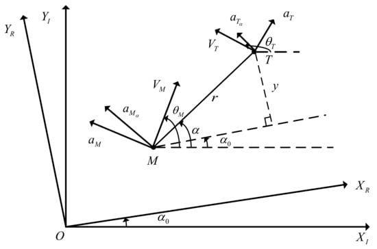
Figure 1.
Two-dimensional guidance geometry.
In terms of the principle of kinematics, the kinematic equation of the missile is written as [1]
where denotes the missile’s position coordinate in the initial inertial frame .
According to the principle of kinematics, the kinematic equation of the target is obtained as [1]
where represents the target’s position coordinate in the initial inertial frame .
To obtain the ZEM in real-time, the reference inertial frame is obtained by rotating the initial inertial frame by a constant angle counterclockwise. During the actual guidance process, the change in the LOS angle is small. Therefore, is generally selected as the initial value of LOS angle such that .
The relative kinematic equation can be linearized in the direction in the reference inertial frame as [22]
where y stands for the component of relative distance r in the direction, v denotes the component of closing velocity in the direction, and stand for the components of the normal acceleration of the missile and of the target in the direction perpendicular to the LOS, respectively, being defined as
Remark 1.
It can be demonstrated that (5) is unavailable when . Hence, the feasible region S is given as .
We define z as the ZEM of the linearized model (4). According to [5], the ZEM of system (4) can be expressed as
where stands for the remaining guidance time and represents the guidance end time. More generally, we call the time-to-go.
Since the speeds of the missile and of the target remain unchanged, the remaining guidance time can be approximately determined as [24]
Remark 2.
In the actual guidance process, if the relative distance r is less than a specific constant value (), then the guidance process can be considered to be over [1]. Therefore, the time-to-go has a lower bound, namely, there exists a positive constant such that .
Since ZEM is a predictor, ZEM guidance has the property of prediction. The ZEM of the guidance system is the difference between the predicted longitudinal distance and the actual longitudinal distance produced by the current longitudinal velocity during the current remaining time-to-go. The purpose of ZEM guidance is to make z approaches zero, namely, to make the prediction difference approaches zero, which ensures the effectiveness of the guidance. A ZEM-based feedback guidance command can be designed according to the property of ZEM. The convergence of ZEM can be guaranteed, thereby ensuring the accuracy and the effectiveness of the ZEM guidance.
Remark 3.
Regarding the effectiveness of ZEM guidance, the following analysis is given. Due to the small change in the LOS angle, the LOS angle in Figure 1 can be linearized as [22]
In the guidance phase, we hope to make z approach zero through the guidance method, namely, . Thus, in the guidance stage, the ZEM guidance is similar to the parallel approach guidance.
In the guidance process, it is hoped that ZEM should quickly converge to the neighborhood of zero within the time-to-go so that the relative distance r converges to zero, ensuring the effectiveness of ZEM guidance. Equation (11) indicates that the unknown acceleration of the target will affect the dynamics of ZEM, thereby affecting the convergence of ZEM.
To enhance the robustness of the ZEM-based inverse optimal guidance law, referring to the idea of PI controller, the integral of ZEM is introduced as a new state. We define the state variables of the augmented system as [25]
We define the disturbance , the composite guidance law , and we derive the state variables and of the augmented system. Then the dynamics of the augmented system can be written as
The idea of this article is to regard the target maneuver as an external disturbance. A disturbance observer is designed to estimate the unknown target acceleration. Then, the estimated values are feedforwarded into the guidance channel to suppress the adverse effects of the unknown target acceleration on the guidance system. On this basis, the integral of the ZEM is regarded as a new system state of augmented system. A ZEM-based inverse optimal robust guidance law based on the augmented system is designed. The guidance accuracy is guaranteed, and the system robustness is improved.
In order to design the composite ZEM-based inverse optimal guidance law, firstly, two lemmas are given.
Lemma 1
(See the work in [10]). Consider a nonlinear affine in the control system as
where contains the system states, contains the system inputs, is a smooth nonlinear vector-valued function with , and is a nonlinear matrix-valued function. Then, the specific form of state feedback control law is
where is optimal with respect to the following performance index function
where is a constant parameter to be designed, is a positive definite matrix, represents a positive definite radially unbounded Lyapunov function of the nonlinear affine system (14), while is given by
Lemma 2.
If there exists a continuous and positive definite Lyapunov function such that [26]
for a control system with bounded initial conditions with
where are class K functions, and and are positive constants, then the solution of state is uniformly bounded.
3. Design of the Disturbance Observer
For the guidance augmented system (13) with unknown target maneuvering, assuming that the states of the system can be measured, the disturbance observer is designed as [16]
where denotes the internal state of the disturbance observer, is a parameter to be designed, and is the observed value of d.
We define the estimated error of the disturbance d as
The derivative of d can be written as
Because , and are all bounded, the derivative of d is also bounded. Namely, there exists a constant such that .
Defining the Lyapunov function and taking the derivative of , we have
It can be concluded from (24) and Lemma 2 that the observed error is uniformly bounded.
We define the estimation error associated with the target’s acceleration as ; in terms of the definition of disturbance d, the following relationships hold
Since the time-to-go has a lower bound and the estimation error of the disturbance observer is uniformly bounded, the estimation error associated with the target’s acceleration is also uniformly bounded.
4. Design of the Inverse Optimal Guidance
In terms of Lemma 1, it is essential to know the Lyapunov function of the system (13) in order to design an inverse optimal guidance law based on disturbance observer and ZEM. Considering the particularity of the system (13), its Lyapunov function is constructed by using the backstepping guidance method given in [27].
Step 1. To design the inverse optimal guidance law based on DO and ZEM, we define
where and is a virtual control law that should be designed.
Taking the derivative of and invoking (13), we can obtain
The virtual control law is designed as
where is a parameter to be computed.
Selecting the Lyapunov function of the system (31) as , differentiating with respect to time, one yields
To ensure the stability of the error system, the composite guidance law is designed as
where denotes the inverse optimal guidance law that should be designed, while represents the feedforward guidance law.
Obviously, the feedforward guidance law term can be designed as
The composite guidance law is to be designed to make the error systems (37) and (31) boundedly stable; for this purpose, the candidate Lyapunov function V is chosen as
Taking the derivative of V with respect to time, can be written as
The specific form of the optimal guidance law (15) is designed according to Lemma 1. Considering that the composite guidance law is designed into two parts, the derivative of V can also be divided into three parts, which can be written as
Considering (37) and (39), the coefficient term of the inverse optimal guidance law can be expressed as
In terms of the specific form of (15), can be designed as
where is a design function.
The design, the analysis and the stability proof of the inverse optimal guidance law based on a disturbance observer and ZEM can be summarized as the following theorem.
Theorem 1.
Considering that the guidance system (13) under external disturbance satisfies Assumptions 1–4, the disturbance observer is designed as (20), the composite guidance law is designed as (34), the feedforward guidance law is designed as (36), and the Lyapunov function is choosen as (38). We choose , and the inverse optimal guidance law is designed as
where will be designed by minimizing the following performance functional
where
Considering (17), we have
5. Simulation
To verify the effectiveness of the inverse optimal guidance law designed in this paper on the missile and target interception system, we design simulations and give a specific analysis in this section. The simulation parameters are given in Table 1. Note: The symbol denotes the initial value of p. In all simulation scenarios, we limit the magnitude of the missile’s normal acceleration to no more than twice the magnitude of the target’s normal acceleration.

Table 1.
Simulation parameters.
In order to reflect the effectiveness of the inverse optimal guidance law mentioned in this article, a contrast analysis is performed with augmented proportional navigation (APN) [22] and parallel approaching guidance (PAG) [23].
5.1. Constant Maneuver
The target maneuver is taken as a constant maneuver, with the amplitude of 9g, where g is the gravity acceleration. In the guidance process, state , state , disturbance and its estimation, target’s acceleration and its estimation, normal accelerations of the missile and of the target, the relative distance, and trajectories of the missile and of the target are shown in Figure 2, Figure 3, Figure 4, Figure 5, Figure 6, Figure 7 and Figure 8.
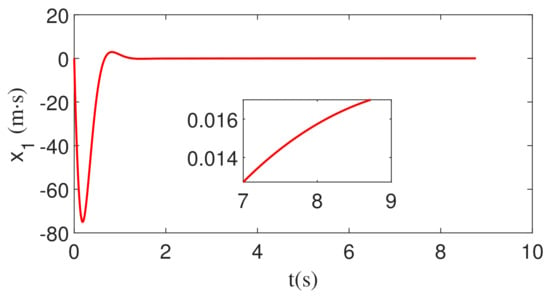
Figure 2.
The change of the integral of ZEM with constant maneuver.
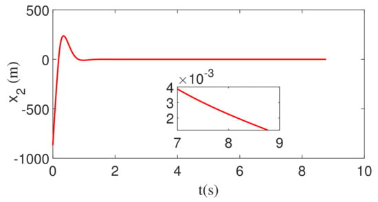
Figure 3.
The change in ZEM with constant maneuver.
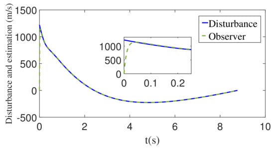
Figure 4.
The disturbance d and its estimation with constant maneuver.
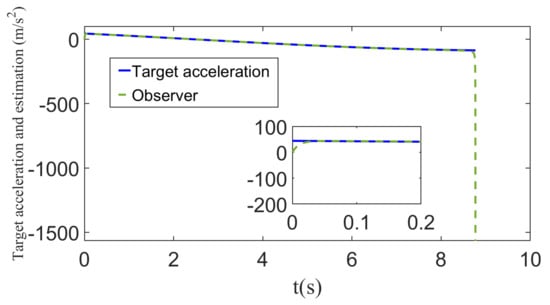
Figure 5.
The target’s acceleration and its estimation with constant maneuver.
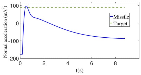
Figure 6.
The normal acceleration of the missile and the target with constant maneuver.
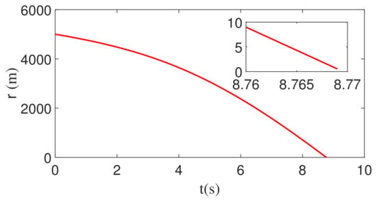
Figure 7.
Time evolution of the relative distance between the missile and the target with constant maneuver.
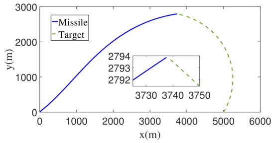
Figure 8.
The flight trajectories of the missile and the target with constant maneuver.
Figure 2 displays the change in the integral of ZEM during the interception process. It can be seen from Figure 2 that state can quickly converge to the neighborhood of 0, which meets the design requirements of the inverse optimal guidance law. Figure 3 is a schematic diagram of the change in the ZEM during the interception process. From Figure 3, we can remark that state quickly converges to the neighborhood of 0, which meets the design requirements of the inverse optimal guidance law.
Under the action of the disturbance observer, the disturbance and its estimation are shown in Figure 4. This figure demonstrates that the unknown disturbance can be estimated quickly and accurately.
Figure 5 demonstrates the maneuvering target acceleration and its estimation. It can be concluded from Figure 5 that the designed disturbance observer can achieve fast and effective tracking, but the tracking error suddenly increases just before the end of the guidance. However, unlike the precise estimation of the disturbance in Figure 4, the estimation of the target acceleration deviates rapidly from the actual value just before the end of the guidance. Considering the relationship between the disturbance estimation error and the target acceleration estimation error, we can see that at the moment before the end of the guidance, although the disturbance estimation error will quickly converge to the small neighborhood of zero, the target acceleration estimation error will grow rapidly due to the gain . Although the estimation of the target acceleration has a large deviation immediately before the end of the guidance, because the moment when the deviation occurs is close to the end of the guidance, and according to Figure 6, the normal acceleration of the missile does not change due to the sudden change in the estimated value of the target maneuvering acceleration. A sudden change occurs so that it does not adversely affect the guidance system.
Figure 7 presents the relative distance between the missile and the target, while Figure 8 demonstrates the trajectory during the guidance process. Figure 7 and Figure 8 prove that the missile achieves precise interception of the target. Comparing Figure 7 with Figure 2 and Figure 3, it can be found that at around 1.8 s, ZEM and its integral are close enough to 0. After 1.8 s, ZEM changes around 0, so the predicted value is always about 0, but due to the limitation of relative distance and relative speed, it takes a considerable time to achieve interception; however, ZEM and its integral are always about 0 to ensure the final successful intercept.
Under the action of inverse optimal guidance and disturbance, the guidance accuracy and the guidance time of different guidance methods are shown in Table 2. The guidance accuracy is defined as the minimum relative distance between the missile and the target during the guidance process, and the guidance time is defined as the time corresponding to the minimum relative distance between the missile and the target. It can be concluded from Table 2 that compared to APN and PAG, the inverse optimal guidance law designed in this paper can effectively improve the guidance accuracy under the premise that the guidance time is close.

Table 2.
Performances of different guidances with constant maneuver.
To verify the robustness and applicability of the guidance method proposed in this paper, we changed the parameters and initial conditions and carried out a series of simulations with the same constraints on the acceleration amplitude. The simulation results are shown in Table 3 and Table 4.

Table 3.
Performances of different parameters with constant maneuver.

Table 4.
Performances of different initial conditions with constant maneuver.
From Table 3 and Table 4, it can be seen that the guidance law designed in this paper is robust and widely applicable. Guidance time is not affected by system parameters, and changes in initial conditions can affect guidance time. All simulation results show that effective interception is achieved.
When the feedback command is corrupted by white noise with noise power 1, the corresponding changes in , , and r are shown in Figure 9, Figure 10 and Figure 11. As can be seen from Figure 9, Figure 10 and Figure 11, , , and r all converge. Therefore, the guidance law designed in this paper is still valid.
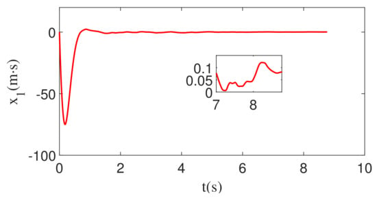
Figure 9.
The change of the integral of ZEM with white noise and constant maneuver.
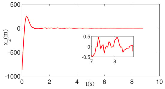
Figure 10.
The change in ZEM with white noise and constant maneuver.
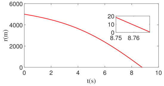
Figure 11.
Time evolution of the relative distance between the missile and the target with white noise and constant maneuver.
5.2. Square Wave Maneuver
The target maneuver is taken as a square wave maneuver with a magnitude of 9 g and a period of 4 s. In the guidance process, state , state , disturbance and its estimation, target’s acceleration and its estimation, normal accelerations of the missile and of the target, and the relative distance between the missile and the target, as well as the trajectories of the missile and the target, are depicted in Figure 12, Figure 13, Figure 14, Figure 15, Figure 16, Figure 17 and Figure 18.
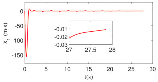
Figure 12.
The change of the integral of ZEM with square wave maneuver.
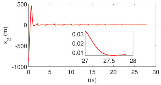
Figure 13.
The change in ZEM with square wave maneuver.
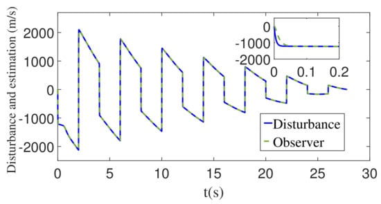
Figure 14.
The disturbance d and its estimation with square wave maneuver.
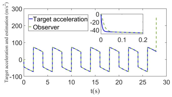
Figure 15.
The target’s acceleration and its estimation with square wave maneuver.
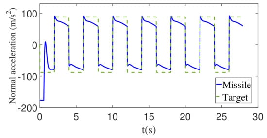
Figure 16.
The normal acceleration of the missile and the target with square wave maneuver.
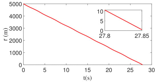
Figure 17.
Time evolution of the relative distance between the missile and the target with square wave maneuver.
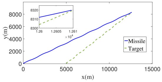
Figure 18.
The flight trajectories of the missile and the target with square wave maneuver.
It can be seen from Figure 12 and Figure 13 that the sign of the target acceleration changes, while the estimated values of the disturbance also change suddenly. The change in disturbance estimate leads to the change in guidance command . Finally, the ZEM and its integral deviate from 0 suddenly. However, after the deviation, it will quickly converge to 0. At the end of guidance, the zero effort miss and its integral converge to the neighborhood of 0, which indicates that the inverse optimal guidance law designed in this paper is still valid.
With the use of disturbance observer, the disturbance and its estimated value is shown in Figure 14. Figure 15 presents the target’s acceleration and its estimated value. It can be seen from Figure 14 and Figure 15 that the estimation accuracy of the disturbance observer is good enough. As the time-to-go decreases, the estimation error of the target’s acceleration increases and, at the same time, the estimated value of the target’s acceleration deviates from the actual value.
From Figure 16, it can be seen that the normal acceleration of the interceptor does not suddenly change due to the sudden change in the target maneuvering acceleration, so it will not cause adverse effects on the guidance system.
As can be seen from Figure 17 and Figure 18, the interceptor achieves accurate interception of the target.
Table 5 shows the guidance accuracy and the guidance time of the guidance method proposed in this paper and APN and PAG. It can be concluded from Table 5 that compared to APN and PAG, the inverse optimal guidance law designed in this paper has advantages over APN and PAG in terms of guidance accuracy. By analyzing the two maneuvering forms, it can be found that the guidance law designed in this paper has better robustness.

Table 5.
Performances of different guidances with square wave maneuver.
To verify the robustness and applicability of the guidance method proposed in this paper, we changed the parameters and initial conditions and carried out a series of simulations with the same constraints on the acceleration amplitude. The simulation results are shown in Table 6 and Table 7.

Table 6.
Performances of different parameters with square wave maneuver.

Table 7.
Performances of different initial conditions with square wave maneuver.
From Table 6 and Table 7, it can be seen that the guidance law designed in this paper is robust and widely applicable. Guidance time is not affected by system parameters, and changes in initial conditions can affect guidance time. All simulation results show that effective interception is achieved.
When the feedback command is corrupted by white noise with noise power 1, the corresponding changes in , , and r are shown in Figure 19, Figure 20 and Figure 21. As can be seen from Figure 19, Figure 20 and Figure 21, , , and r all converge. Therefore, the guidance law designed in this paper is still valid.
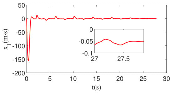
Figure 19.
The change of the integral of ZEM with white noise and square wave maneuver.
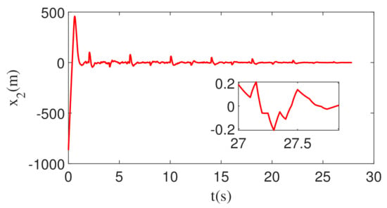
Figure 20.
The change in ZEM with white noise and square wave maneuver.
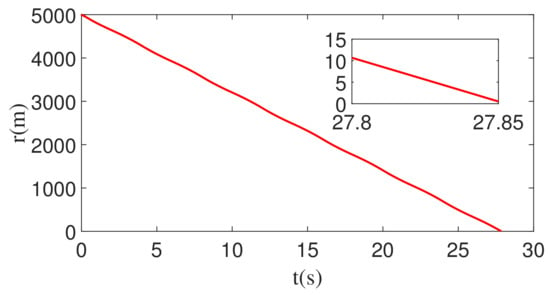
Figure 21.
Time evolution of the relative distance between the missile and the target with white noise and square wave maneuver.
6. Conclusions
Aiming at the problem of maneuvering target interception, an inverse optimal guidance law based on a disturbance observer and ZEM is proposed in this paper in two-dimensional form. Firstly, the model is linearized, and the integral of ZEM is introduced to obtain the augmented system. Then a disturbance observer is designed to estimate the acceleration of the maneuvering target, and it is compensated by the feedforward technique. The Lyapunov function is constructed based on the backstepping method, an inverse optimal guidance law being designed. Finally, the simulation experiment shows that compared with APN and PAG, the guidance method designed in this paper improves the guidance accuracy significantly. For constant-value maneuvers, the guidance accuracy is improved by 85% and 80% compared to APN and PAG, respectively. For square wave maneuvers, the guidance accuracy is improved by 78% and 75% compared to APN and PAG, respectively.
Author Contributions
All authors contributed to this study. B.M. contributed to the methodology, validation and writing—original draft preparation. M.C. contributed to the conceptualization, investigation and project administration. Y.S. contributed to the formal investigation and resources. M.L. contributed to the formal analysis and data curation. All authors have read and agreed to the published version of the manuscript.
Funding
This work was supported in part by the Key R & D projects (Social Development) in Jiangsu Province of China (BE2020704); Aeronautical Science Foundation of China (20200007052001).
Institutional Review Board Statement
Not applicable.
Informed Consent Statement
Not applicable.
Data Availability Statement
The data presented in this study are available on request from the corresponding author.
Conflicts of Interest
The authors declare no conflict of interest.
References
- Zarchan, P. Tactical and Strategic Missile Guidance; American Institute of Aeronautics and Astronautics: Reston, VA, USA, 2012. [Google Scholar]
- Zhou, K.; Doyle, J.C. Essentials of Robust Control; Prentice Hall: Upper Saddle River, NJ, USA, 1998; Volume 104. [Google Scholar]
- Weiss, M.; Shima, T. Optimal linear-quadratic missile guidance laws with penalty on command variability. J. Guid. Control Dyn. 2015, 38, 226–237. [Google Scholar] [CrossRef]
- Newman, B. Strategic intercept midcourse guidance using modified zero effort miss steering. J. Guid. Control Dyn. 2012, 19, 107–112. [Google Scholar] [CrossRef]
- Lee, C.-H.; Shin, H.-S.; Lee, J.-I.; Tahk, M.-J. Zero-effort-miss shaping guidance laws. IEEE Trans. Aerosp. Electron. Syst. 2017, 54, 693–705. [Google Scholar] [CrossRef]
- Zheng, L.-W.; Jing, W.-X.; Zhang, J.-Y. Zero Effort Miss Formulation for Longer Range Targeting. In Proceedings of the 2007 Chinese Control Conference, Zhangjiajie, China, 26–31 July 2007; pp. 865–869. [Google Scholar]
- Li, H.; Li, H.; Cai, Y. Efficient and accurate online estimation algorithm for zero-effort-miss and time-to-go based on data driven method. Chin. J. Aeronaut. 2019, 32, 2311–2323. [Google Scholar] [CrossRef]
- Guo, Y.; Hawkins, M.; Wie, B. Applications of generalized zero-effort-miss/zero-effort-velocity feedback guidance algorithm. J. Guid. Control Dyn. 2013, 36, 810–820. [Google Scholar] [CrossRef]
- Wang, P.; Guo, Y.; Ma, G.; Wie, B. Two-phase zero-effort-miss/zero-effort-velocity guidance for mars landing. J. Guid. Control Dyn. 2021, 44, 75–87. [Google Scholar] [CrossRef]
- Krstic, M.; Tsiotras, P. Inverse optimal stabilization of a rigid spacecraft. IEEE Trans. Autom. Control 1999, 44, 1042–1049. [Google Scholar] [CrossRef]
- Ma, H.; Chen, M.; Wu, Q. Inverse optimal control for unmanned aerial helicopters with disturbances. Optim. Control Appl. Methods 2019, 40, 152–171. [Google Scholar] [CrossRef]
- Rusnak, I.; Weiss, H.; Hexner, G. Optimal guidance laws with prescribed degree of stability. Aerosp. Sci. Technol. 2020, 99, 105780. [Google Scholar] [CrossRef]
- He, S.; Lee, C.-H. Optimal impact angle guidance for exoatmospheric interception utilizing gravitational effect. IEEE Trans. Aerosp. Electron. Syst. 2018, 55, 1382–1392. [Google Scholar] [CrossRef]
- Wen, X.; Zhang, J.; Yao, X. Estimation and rejection of sinusoidal disturbance with unknown frequency using cascade disturbance observer. Trans. Inst. Meas. Control 2021, 43, 2647–2657. [Google Scholar]
- Chen, S.; Ma, C. A novel finite-time extended state observer for a class of nonlinear system with external disturbance. Int. J. Innov. Comput. Inf. Control 2020, 16, 1811–1820. [Google Scholar]
- Chen, W.-H.; Yang, J.; Guo, L.; Li, S. Disturbance-observer-based control and related methods—An overview. IEEE Trans. Ind. Electron. 2015, 63, 1083–1095. [Google Scholar] [CrossRef]
- Ren, C.E. Adaptive fuzzy disturbance observer-based control for nonlinear uncertain systems with general exogenous disturbances. Int. J. Fuzzy Syst. 2021, 23, 1453–1461. [Google Scholar] [CrossRef]
- Dwivedi, P.; Bhale, P.; Bhattacharyya, A.; Padhi, R. Generalized estimation and predictive guidance for evasive targets. IEEE Trans. Aerosp. Electron. Syst. 2016, 52, 2111–2122. [Google Scholar] [CrossRef]
- Liu, W.; Wei, Y.; Duan, G.; Hou, M. Integrated guidance and control with input saturation and disturbance observer. J. Control. Decis. 2018, 5, 277–299. [Google Scholar] [CrossRef]
- Yang, J.; Wu, C.; Li, S. Distributed composite autopilot design for bank-to-turn missiles with optimized tracking based on disturbance observers. Trans. Inst. Meas. Control 2017, 39, 1123–1138. [Google Scholar] [CrossRef]
- Zhang, Z.; Man, C.; Li, S.; Jin, S. Finite-time guidance laws for three-dimensional missile-target interception. Proc. Inst. Mech. Eng. Part G J. Aerosp. Eng. 2016, 230, 392–403. [Google Scholar] [CrossRef]
- He, S.; Lee, C.-H.; Shin, H.-S.; Tsourdos, A. Optimal Guidance and Its Applications in Missiles and UAVs; Springer: Berlin/Heidelberg, Germany, 2020. [Google Scholar]
- Shen, Y.; Chen, M.; Zheng, Z.; Guo, H. Event-triggered-backstepping-based parallel approaching guidance method for maneuvering target interception. Guid. Navig. Control 2022, 2, 2250005. [Google Scholar] [CrossRef]
- Morgan, R.W. A New Paradigm in Optimal Missile Guidance; The University of Arizona: Tucson, Arizona, 2007. [Google Scholar]
- He, S.; Lee, C.-H. Optimal proportional-integral guidance with reduced sensitivity to target maneuvers. IEEE Trans. Aerosp. Electron. Syst. 2018, 54, 2568–2579. [Google Scholar] [CrossRef]
- Chen, M.; Shi, P.; Lim, C.-C. Adaptive neural fault-tolerant control of a 3-dof model helicopter system. IEEE Trans. Syst. Man Cybern. Syst. 2015, 46, 260–270. [Google Scholar] [CrossRef]
- Khalil, H.K. Nonlinear Control; Pearson: New York, NY, USA, 2015; Volume 406. [Google Scholar]
Publisher’s Note: MDPI stays neutral with regard to jurisdictional claims in published maps and institutional affiliations. |
© 2022 by the authors. Licensee MDPI, Basel, Switzerland. This article is an open access article distributed under the terms and conditions of the Creative Commons Attribution (CC BY) license (https://creativecommons.org/licenses/by/4.0/).