1. Introduction
The need to monitor the health of the blades of jet engines and stationary turbines results from the well-known problems with blade damage [
1] caused by ingested foreign objects or material fatigue. Blade Health Monitoring (BHM) systems have good commercial prospects, especially in power generation turbines, which are increasingly operated in the off-design mode due to fluctuating market demand for energy. There are also some successful examples of on-board BHM systems in aviation, including the TS-11 trainer [
2] and F-35 fighter [
3], with magnetic sensors installed in the engine compressing section.
The digital transformation of aviation requires new robust sensors for engine development, ground maintenance, and in-flight health management and prediction. Magnetic sensors are better suited for monitoring systems than optical [
4] or capacitive sensors [
5,
6] because they do not require cleaning, and their signals can be processed using commonly available electronic systems. However, only sensors with high durability and reliability are acceptable.
In compressors and steam turbines, blade tip timing (BTT) systems are widely used and mature [
7,
8], while, in gas turbines, there are still significant technical challenges. This is due to the low durability and high cost of the suitable probes. The leading engine OEMs spend hundred thousand dollars on a set of sensors needed for a single turbine test.
A turbine disk differs significantly from a fan in terms of blade vibration measurement. It is not only in higher operating temperature and dissimilar geometry of the tip but also in the high stiffness of the blades and its different way of supporting the rotor. The deflections of the turbine blades are several dozen times smaller than the fan blades and require measurement systems with a class of higher accuracy and spatial resolution [
9]. In addition, the structural resonances of the casing, the axial movement of the shaft, and vibrations of the turbine disk can hinder the blade vibration measurements.
BTT and tip clearance (TC) sensors have a lot in common, and some types offer both measurements [
10]. However, sensors can be optimized either for clearance or vibration measurement. Due to the demand for higher turbine efficiency, the industry shows more interest in high-temperature TC sensors. Capacity probes are mainly used for this purpose, but several measurement solutions based on active eddy-current principle have been proposed, e.g., References [
11,
12,
13]. Some interesting sensor designs in low temperature co-fired ceramics (LTCC) technology have also been presented [
14,
15,
16].
Permanent magnet inductive sensors known as passive eddy current sensors [
17,
18] do not have a high-frequency generator and detector. There is, thus, higher bandwidth and no problem with cross-talk and the carrier frequency related to the operation of the generator in active eddy-current sensors [
19,
20]. The disadvantage of passive sensors is the dependence of the signal on the speed, but this is much less relevant in BTT, especially in constant-speed power generation machines. Tip clearance measurement is also possible but requires dynamic calibration. Another problem is the decrease in magnetization of permanent magnets with increasing temperature. At the Curie temperature, ferromagnetic materials become paramagnetic, i.e., they completely lose their magnetic properties and are no longer a source of a magnetic field. To avoid this, the permanent magnet can be replaced in the sensor with a DC-powered electromagnet [
21].
Standard inductive sensors measure blade vibrations and rotational speed in machines, such as compressors or steam turbines, where the sensor operating temperature does not exceed 125 °C. Their high temperature versions designed for turbochargers are specified at 230 °C [
22,
23]. However, different sensor materials and manufacturing technologies are required for high pressure compressors and gas turbines. The main difficulty in the design of high-temperature sensors is developing low-temperature sensor production technologies, which, at the same time, guarantee the strength of the structure at an operating temperature of 1000 °C or higher. In particular, it is advisable to use materials and cements that do not need to fire the assembled sensor since this would deprive the magnets of their magnetic properties.
Some high temperature BTT sensors (optical and capacitive) are rated for gas temperatures as high as 1200–1400 °C, but they are designed for short-term use and therefore cannot be used in BHM systems. Moreover, very few other sensors are constantly used in the engine hot section due to the high cost and the lack of materials and technologies to ensure durability. The exceptions include various types of thermometers, such as optical fibers [
24,
25], Pt100 sensors, and thermocouples, which are usually duplicated. Piezoelectric transducers, such as pressure [
26,
27] and vibration transducers [
28], have a similar problem with the Curie temperature as in inductive sensors, but there is a group of materials that does work above 600 °C [
29,
30].
Microwave sensors [
9,
31,
32] can be made of materials that can be used up to 1400 °C. Unfortunately, changes in distances in the turbine caused by thermal expansion shift the sensor’s operating point, which can be compensated for by using complex electronics. Capacitive and optical BTT/TC sensors are more mature than microwave ones, but their electronics are similarly fragile and complex, thus not being ready for in-flight or field operation.
The article presents selected design solutions and the results of rig testing of an inductive sensor with a permanent magnet, which can operate in gas turbines at a temperature up to 900 °C. A series of measurements was made to verify the suitability of the sensor for operation in a gas turbine. In order to check the sensor’s performance at elevated temperature, the head of the sensor was heated with a blowtorch from 25 °C to 1100 °C, comparing its signal with the response of a cold sensor aimed at the same test wheel.
2. Materials and Methods
2.1. Working Principle
The inductive tip-timing sensor is designed to measure the arrival time of blades (TOA). Like an electric generator, it uses electromagnetic induction to produce output signal as blades pass. The sensor consists of a probe and a specialized conditioning system [
33], which can work near the turbine at a temperature as high as 150 °C if it is made from high temperature electronic components [
34]. The design of the probe and conditioning system must be adapted to the blade material, operating temperature, and the length of the signal cable. Higher flexibility was achieved here, inter alia, by using programmable gain amplifiers (PGA).
The field of the sensor is shaped in such a way that it reaches the blade tip. This make the blade an integral part of the electromagnetic circuit (
Figure 1). The diagram illustrates the electrodynamic interaction between the induced currents in the passing blade
and the sensor winding
.
and
are the equivalent blade resistance and leakage reactance, and
and
are the sensor resistance and reactance. The conditioning system (
Figure 2) includes a current-voltage converter (preamplifier), which produces the voltage output signal proportional to the sensor current
.
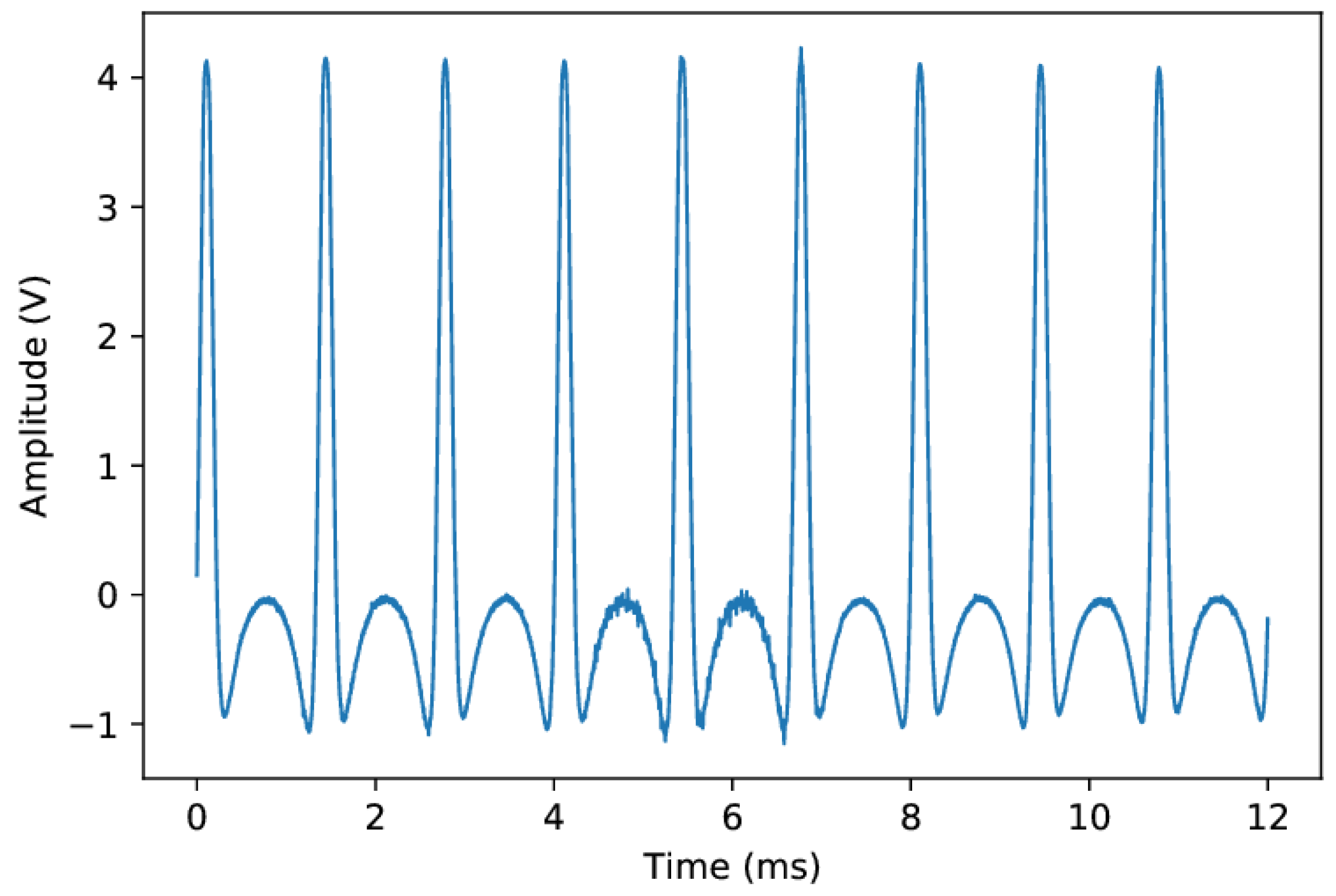
The quality of the generated signal is related to the waveform parameters, such as pulse amplitude, rise time, and signal noise ratio [
35]. The voltage reaches its maximum when the maximum energy of interaction between the blade and the sensor occurs [
21]. Obtaining pulses of the appropriate quality requires the optimization of the magnetic circuit of the sensor so that the moment of force which it acts on the blade is the greatest. This is especially true if the blade is not ferromagnetic.
The range of the sensor should correspond to the variation of tip clearance during machine operation. It must not be too large, especially in turbine where the blades are numerous and relatively densely spaced around the circumference. Then, the sensor interacts with two or three blades at the same time, which reduces the signal quality and resolution of the position measurement.
An earlier version of the sensor is presented in Reference [
18]. The probe design has recently been modified to improve durability, hot gas resistance, and output characteristics. The solution is based on the patented high-temperature magnetic measurement technology [
36] based on the use of a pair of permanent magnets and a winding with a low number of turns. The use of two magnets prevents the decrease in the magnetic properties of the sensor under the effect of exhaust gases. A low-turn winding [
37] and related low resistance reduce the impact of temperature on coil impedance and sensor performance. In the presented sensor, the winding has tree turns and a diameter of 7 mm. Its resistance is 100
, and its inductance is 2 µH.
The inductive sensor (
Figure 1) can detect the rotating blades made of conductive ferromagnetic or non-magnetic materials due to the wide range of gains available in the conditioning system. It can be installed in a threaded hole and fixed with an M16x1 nut. Alternatively, a bracket with a 19-mm hole and two M16x1 nuts (
Figure 3) can be used.
2.2. Sensor Design
The probe consists of a steel body, a magnetic circuit and a heat-resistant ceramic insulator. The two-piece body is the main structural element of the sensor, designed to operate in the turbine zone under thermal stress and high vibration levels. The steel body, in order to guarantee the sensor’s durability, should have proper walls of appropriate thickness, and the threads used should ensure fastening. Inside, there is an insulator, and inside the insulator-fixed elements of the magnetic circuit, i.e., two magnets and a winding.
The insulator is made of ceramics (AlO 99.9% purity), fired in 1600 °C, which can operate in high pressure and temperature existing in gas turbine. Above 300 °C, ceramics becomes a semiconductor whose wave impedance is a function of the concentration of ions in the exhaust gas. Due to the high purity, the wave impedance of the ceramics is then about 120 (not 1 as for the contaminated one). The input impedance of the amplifier and the sensor winding is matched to the wave impedance of the hot insulator.
The ceramic insulator protrudes about 10 mm from the steel body. In this temperature range, there are no other materials than ceramics that could act as an insulator. Unfortunately, if it is hit when cold, it can break easily. Due to its fragility, it should be covered as much as possible by the steel body.
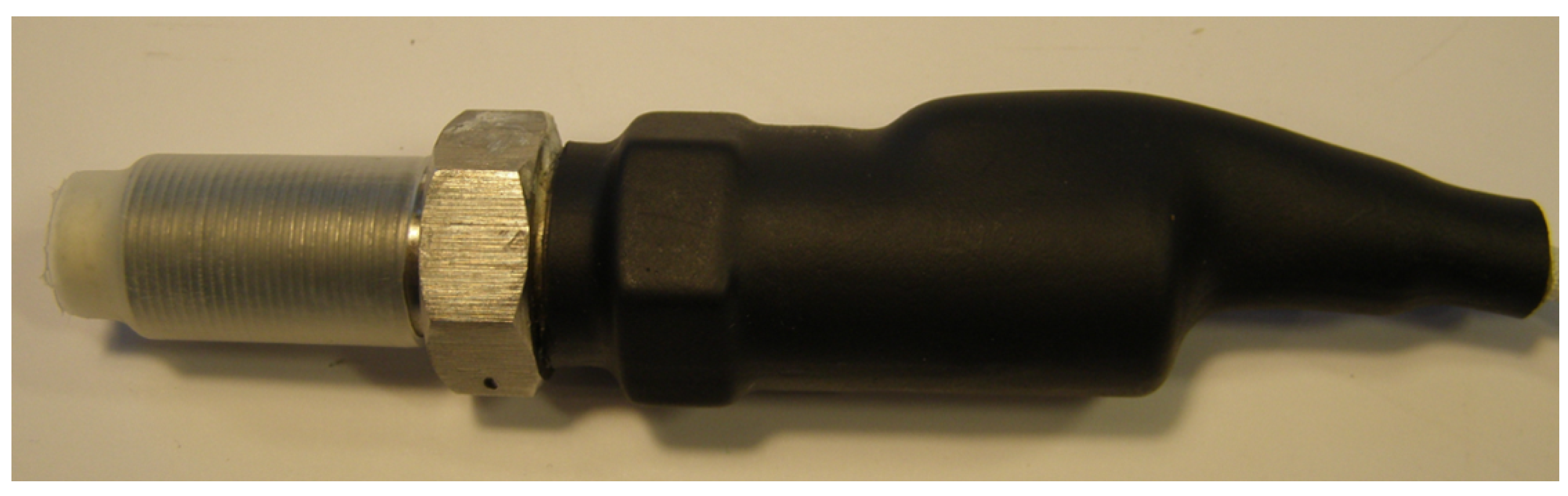
The assembled sensor (
Figure 4) cannot be repaired or disassembled without destroying it. The elements of the electromagnetic circuit inside the sensor cannot move. The correctness of the assembly or any damage can be checked using Computed Tomography (CT). You can also measure the winding resistance and the magnetic field of the magnets with a magnetometer.
The signal cables have glass-fiber insulation with an operating temperature of 800 °C. The cables can be extended with a standard twisted pair (Ethernet cable) if needed, but this reduces the signal-to-noise ratio. The maximum possible length (typically 12 m) depends on the application: the greater the gain, the shorter the cable should be. The operation of the sensor requires a microprocessor-controlled conditioning system [
34], which amplifies the signal and generates a digital TTL signal.
2.3. Permanent Magnets
Strong permanent magnets (PM) are made from alloys of rare-earth elements [
38,
39]. Among the available types of magnets, ferrite and neodymium magnets do not work at temperatures above 200 °C (
Table 1). They lose a lot of their magnetic field, even at a moderate temperature as high as 125 °C [
40]. All magnets demagnetize when heated to the Curie temperature or when a strong electromagnetic field from an AC electromagnet is applied [
41].
The presented sensor uses two cooperating magnets [
36]: measuring AlNiCo and supporting samarium (SmCo)—
Figure 5. The magnets are positioned on the sensor axis along which the temperature gradient occurs. The AlNiCo magnet works at a higher temperature but is supported by the field of the stronger samarium magnet. This solution makes it difficult to demagnetize the AlNiCo magnet even though it is operated over the maximum temperature it is rated for, i.e., 520 °C but below its Curie point. Moreover, the elevated temperature is a factor that strengthens its field. This phenomenon is also used in the manufacturing of permanent magnets to improve their performance by applying strong magnetic fields and elevated temperature in the process known as magnetic thermal annealing or artificial magnetic aging [
42,
43].
The turbine heats up considerably when the engine is shut down, when airflow ceases and the structure is not cooled. Such states in sensors with a single magnet causes their irreversible destruction. In the presented two-magnet sensor, moderate overheating stabilizes and strengthens the measurement magnet. The signal parameters are maintained if the temperature of the external part of the sensor does not exceed 400 °C.
2.4. Sensor Installation
During operation in a gas turbine, the probe comes into contact with gas at a temperature of up to 1100 ºC. Therefore, it should be mounted in such a way that makes heat dissipation possible so that the temperature of the external part of the sensor does not exceed 150–200 ºC during normal operation. The cooling medium may be bleed air or bypass air in a turbofan.
The sensor is installed manually in the turbine casing. It is mounted by screwing the sensor into the socket prepared in the engine nozzle to the appropriate distance from the blade. After positioning the sensor, it is fixed with a nut and connected to the configured amplifier.
Installing the sensor is the riskiest moment for its health and durability, especially for the cables and the insulator. Personnel handling sensors should be properly trained and should use the proper tools. The threads should be made so that it is not necessary to use high torques for fastening. The cables should be carefully fastened in conduits so that they are not exposed to abrasion and erosion. Fitting sensors requires removing the outer casing of the engine and usually costs much more than sensors.
2.5. Sensor Durability
Operators are interested in achieving the durability of the sensors at least several thousand flight hours, which is the typical time between overhaul (TBO) of engines, but it is difficult to simulate and prove in laboratory conditions. This order of durability was achieved in steam turbines where the operating temperature is moderate (about 100 °C), but the main problem is a humid environment and corrosion [
44]. In case of mechanical damage to the insulator, the sensor loses its tightness, and the winding and magnets corrode. In a damaged sensor, the response of the electromagnetic circuit to the blade transition decreases and gradually disappears, which is manifested by a lower signal-to-noise ratio of the output signal.
During the operation of a gas turbine, there are noticeable changes in the stand-off distance between the blades and the sensor due to rotor vibrations and thermal expansion. This is why the ceramic insulator should be flush-mounted and must not protrude into the abrasive layer. If the stand-off clearance is too small, the sensor may be rubbed and damaged [
11,
18].
Further work is required to predict sensor health and detect symptoms of signal deterioration. Fernandez et al. [
45] tested performance of PMs subjected to cyclic magnetization and demagnetization in temperature up to 135 °C. They found that magnets’ cycle life decreases with operating temperature. Here, the known methods for assessing the waveform quality are used, such as monitoring and statistical analysis of pulse amplitude, signal-to-noise ratio, rise time, and the number of missing and surplus blades.
2.6. Rig Testing
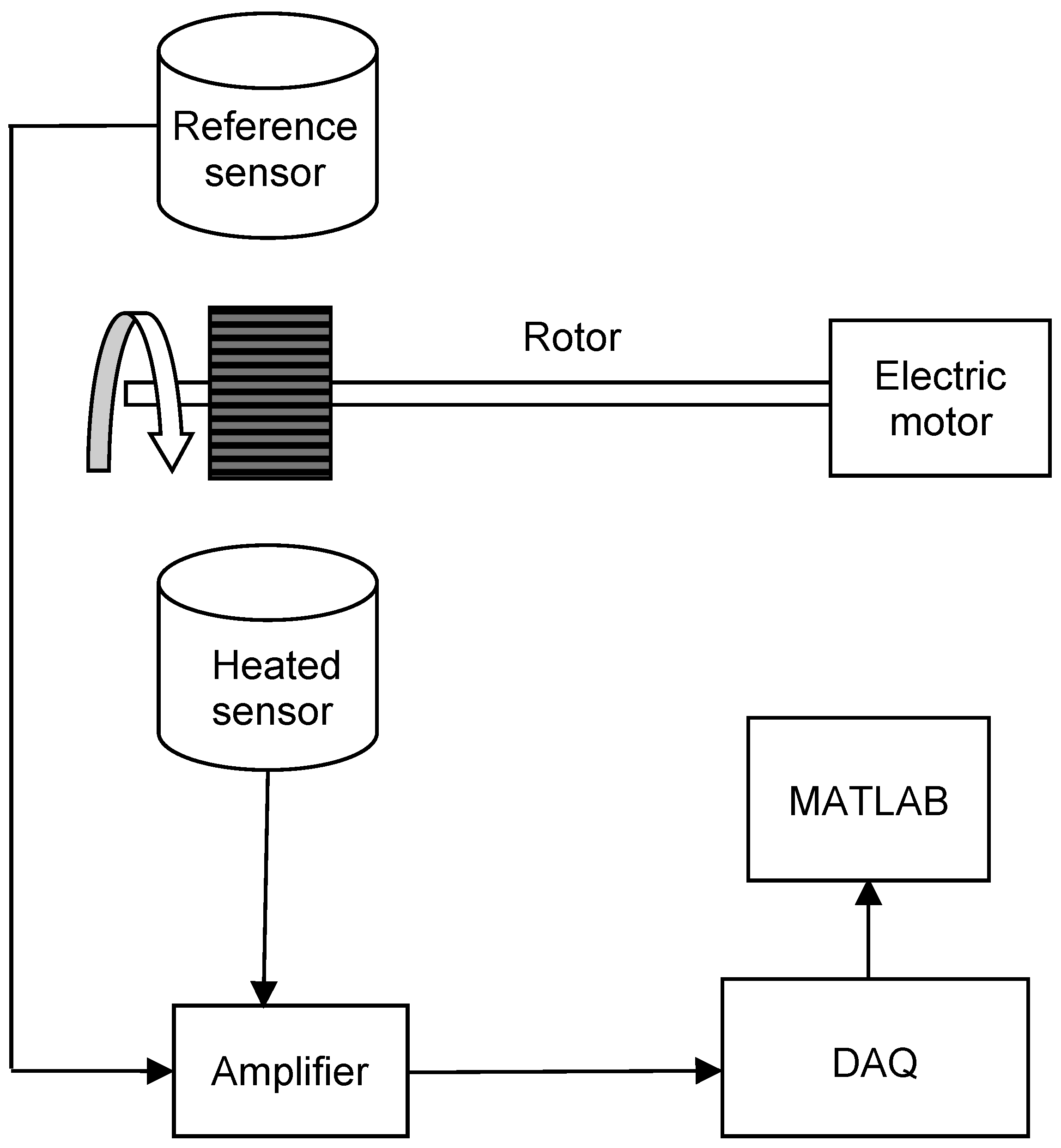
A commercial rotor rig (Bently Nevada RK-4 Rotor Kit) was adapted to test BTT / TC sensors. A test wheel with 9 steel blades and a diameter of 120 mm was mounted on the shaft. The motor control unit was used to set the desired speed up to 10,000 rpm. The NI PXI-1065 computer equipped with PXIe-6358 module and software developed in LabView was the data acquisition system (DAQ). The block diagram of the measurement system is shown in
Figure 6.
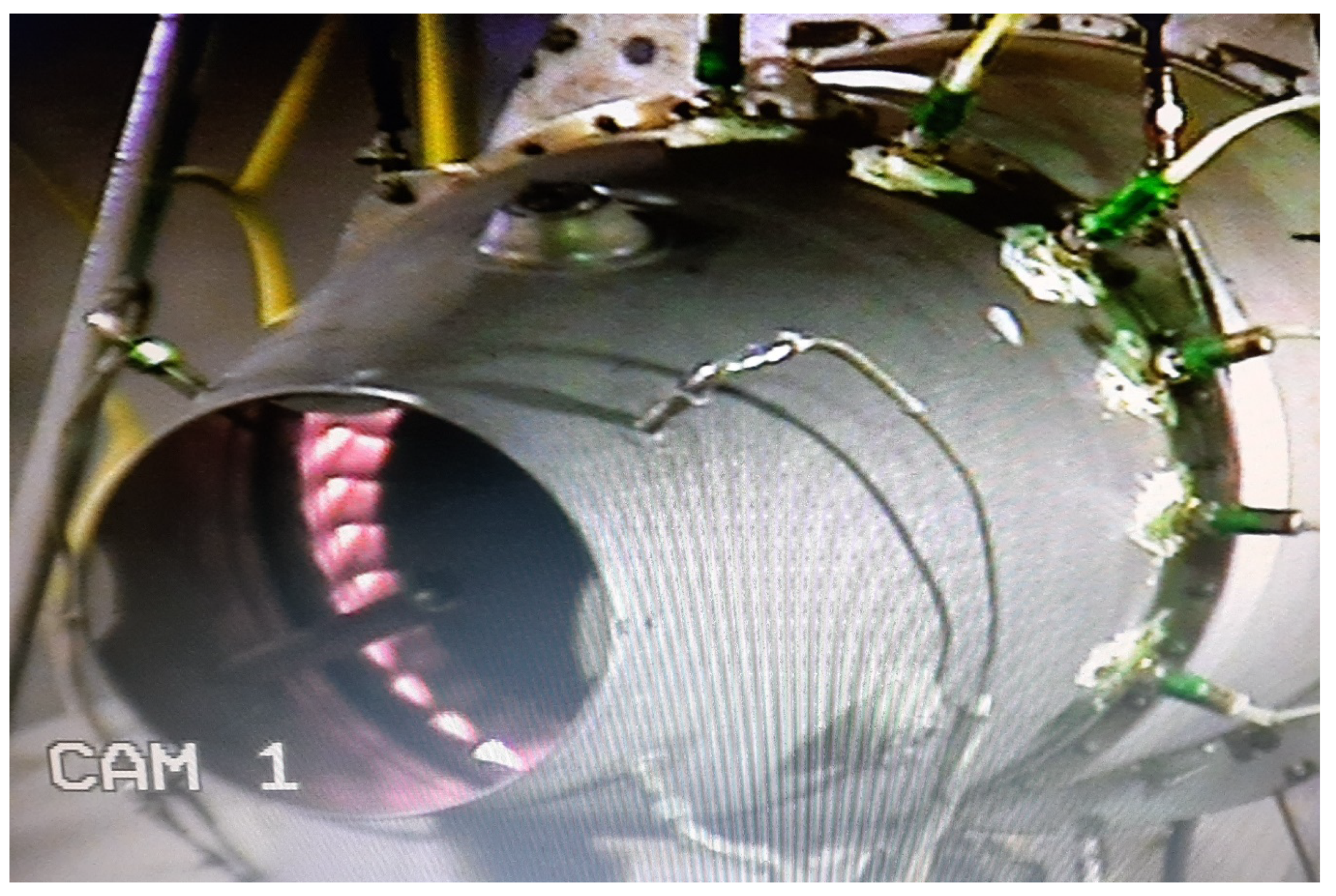
Two sensors were mounted around a test wheel.
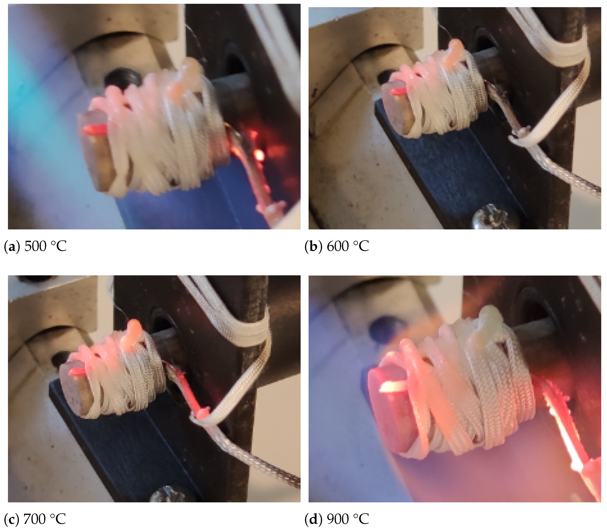
Figure 7 shows the tested sensor heated with a blowtorch on the right and the reference sensor in the bottom left corner. The temperature of the probe was measured with a thermocouple, which was attached to the ceramic insulator by means of glass silk thread, resistant to temperature up to 1060 °C. The test consisted of heating the sensor for 3 min until the selected temperature was stable and measuring the sensor signal at a constant speed of 7000 rpm for 30 s. This procedure was repeated a few times for temperature raised from 50 to 1100 °C. The bladed wheel was moved away from the sensors during heating, but it was moved back for spinning.
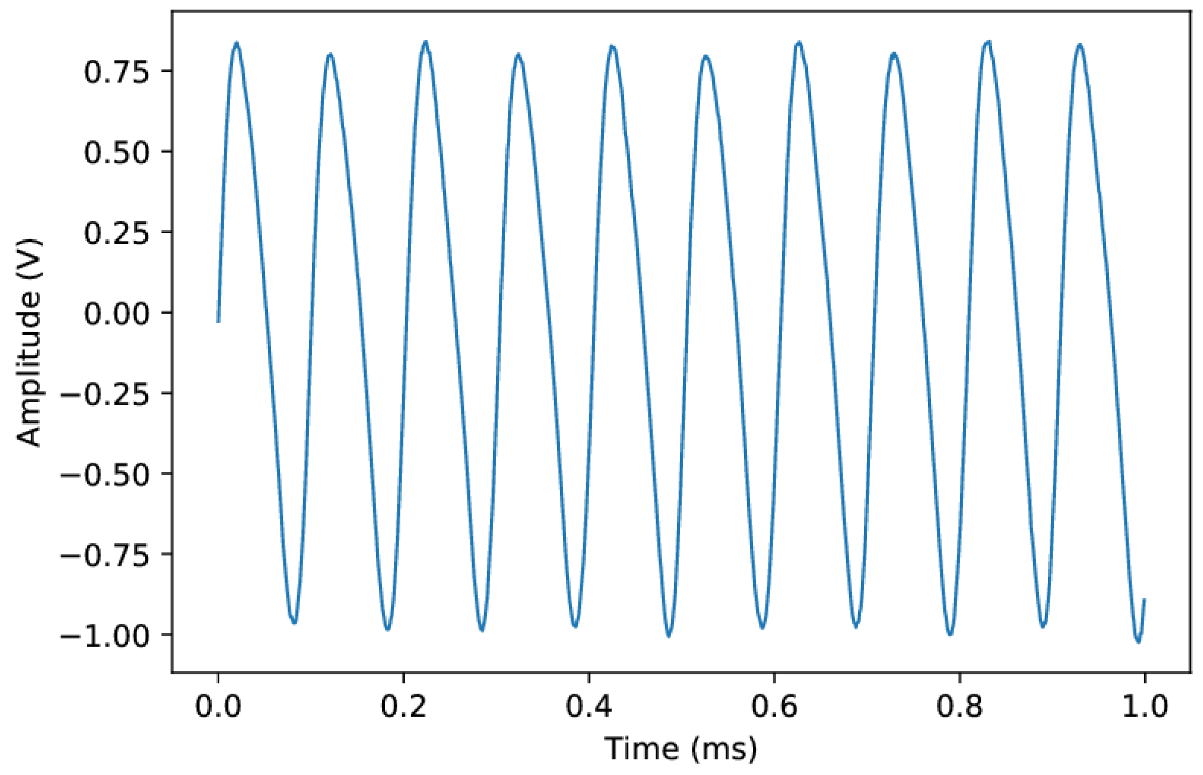
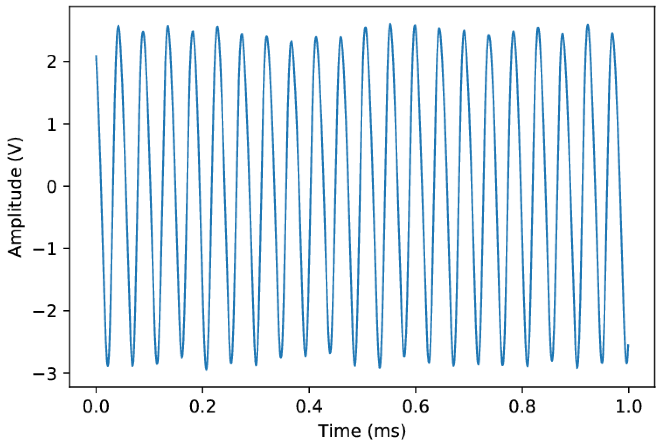
A series of measurements were made with gradually increased temperature (
Figure 8). The signals from the sensors were fed into the multi-stage adjustable amplifier of the conditioning system. The amplified signals were sampled with frequency of 500 kHz. For each temperature point, 20 s of data was recorded in the pcm format and processed in MATLAB.
2.7. Signal Processing
For each temperature, the Hilbert transform
was calculated for sensor output
, for the data frame of 20 s. It was used to get the signal envelope
as the modulus of the analytic signal:
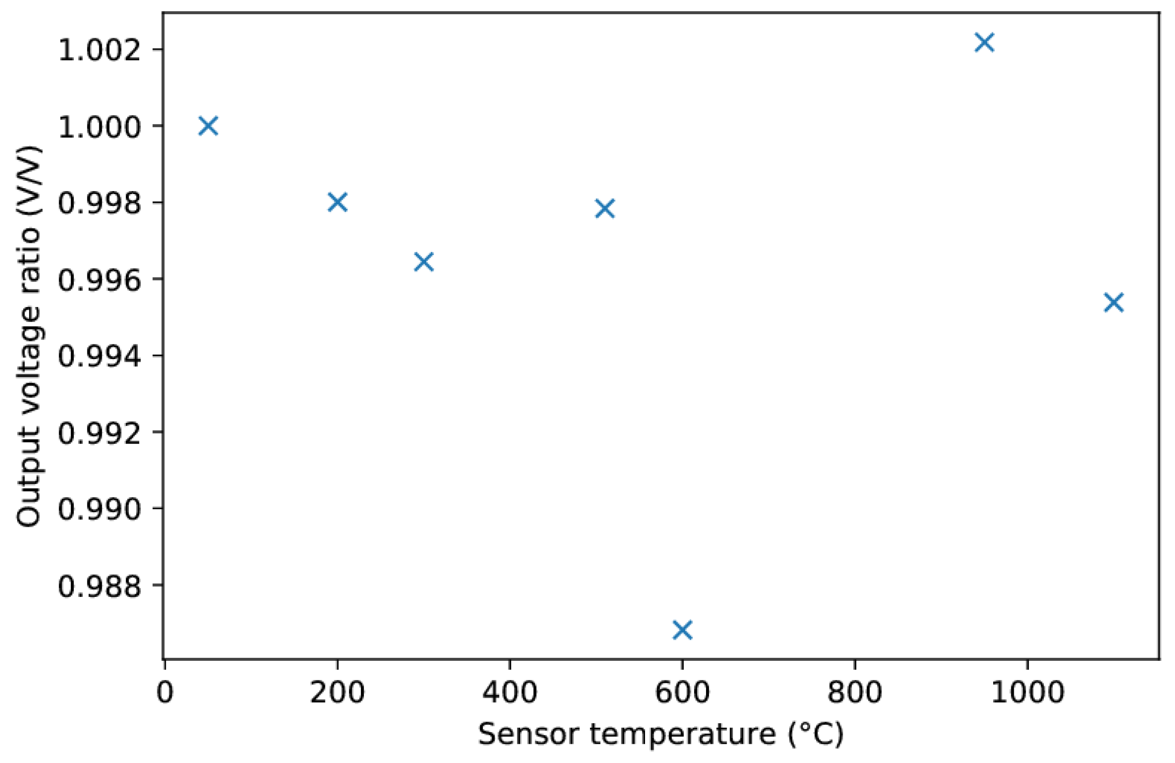
The average envelope voltage of the hot sensor was then related to the cold sensor’s one.
4. Discussion
Presented rig and engine tests confirmed that hot gases had negligible influence on the sensor output signal. Moreover, these preliminary engine tests verified the correct operation of a set of sensors installed in the turbine casing. This provides a solid basis for blade vibration analysis and further studies of turbine dynamics. Our prior measurements in this turbine were performed with a single microwave sensor [
9] or, later, with a previous version of the inductive sensor [
18]. There were considerable difficulties in identifying the observed vibration responses due to the inability to conduct multi-sensor analysis.
The presented sensor has significant improvements in relation to its previous version. Firstly, an insulator with much better parameters and a lower production spread was used. It was possible, thanks to the improvement of the production technology, inter alia, to reduce shrinkage after firing. Low porosity and high purity and hardness of the ceramics were achieved. These factors directly affect the durability and performance of the sensor.
Based on operating experience with earlier versions, the geometry of the sensor and its manufacturing process were fine-tuned. In particular, the magnetic circuit of the sensor was enhanced by more efficiently matching its impedance with the input impedance of the amplifier. The implemented method of assembling the circuit and guiding the winding increased the reliability of the sensor. Thanks to the maturation of sensor’s manufacturing technology, an acceptable repeatability of its parameters was achieved, which made it possible to build a multi-probe BTT system. However, sensor optimization has natural limitations related to the turbine environment, such as limited space and problems with heat dissipation.
The presented rig experiment lacked a screen simulating the turbine casing as in Reference [
11]. As a result, the sensor received more heat than in the engine, which is even better for checking its robustness. However, the measurement of temperature at only one point was a significant simplification, especially in view of the temperature gradient along the sensor needed for its correct operation. This is due to the fact that, in a standard engine, only the average exhaust gas temperature (EGT) is available. More thermocouples should be used in the next test, or even a thermal imaging camera. It is also planned to carry out a numerical thermal analysis of the sensor. To prove the durability of the sensor, a burner rig should be built, able to perform automatic heat cycles, in which the temperature changes according to the mission profile of the aircraft engine.
Although a complete thermal analysis of the sensor has not been done, it was confirmed that both magnets were not overheated in the presented tests. Firstly, the maximum turbine inlet temperature, i.e., 800 °C, known from engine specifications, EGT measurement, and performance calculations, is lower than the Curie point of the AlNiCo magnet. Secondly, a similar sensor was tested with an infrared camera at this engine at the take-off speed, showing 175 °C at the cold end and 265 °C at the hot end of the sensor. These numbers are in the operating temperature range of the used SmCo magnet. In addition, no indication of deterioration of the output signal was observed in the presented tests.
Tests run on a legacy turbojet may seem not quite representative for operation of a stationary gas turbine or a commercial turbofan engine. Earlier experience with the military turbofan shows that, in bypass engines, it is more difficult to install and service the sensor, but there are better conditions for the natural cooling of the sensor. The use of a turbojet in the engine design is beneficial from the point of view of the cost of testing and the labor consumption of sensor assembly. However, the presented preliminary tests are insufficient to validate the reliability and durability of the sensor. Although the earlier version of the inductive sensor operated in a gas turbine for about 30 h, and at least 3 years in a steam turbine, it was possible to perform only a short engine test with this sensor design.
As for the data collected during the engine tests, we intend to carry out further analysis based on objective criteria, both in terms of waveform quality and blade vibration. In particular, the waveform parameters of the tested sensors in the different operating points will be compared. An uncertainty analysis will be carried out, which will lead to the selection of the optimal sampling rate and triggering method and determination of the arrival times for all sensors. This will enable the blade vibration analysis to be performed using circumferential least squares [
7,
46].
It is expected that the acquisition system will be properly set up to generate online TOA values in planned engine tests. This will enable the characterization of turbine blade vibrations and the application of external excitation to observe responses that are normally not measurable. It is planned to equip the engine with a sensor once per revolution and an accelerometer, which will facilitate the interpretation of tip timing data.
Due to the physical limitations of the technology related to Curie temperature, the presented magnetic sensors with permanent magnets cannot replace capacitive or optical sensors used in the development of modern high pressure turbines. However, inductive sensors can be suitable and cost-competitive in applications where gas temperature is moderate and where there is no access to a sensor for maintenance. Moreover, active cooling can significantly extend the scope of their application. The flexibility of using this type of sensor in the engine and its signal-to-noise ratio was considerably enhanced by introducing a smart conditioning unit [
34], able to monitor and control the output signal level.
5. Conclusions
The paper presents the design and validation of a high-temperature magnetic sensor for blade health monitoring. It discusses the selection of components and technologies to build a robust and durable sensor, as well as challenges related to its installation in a turbine and efforts to ensure trouble-free operation. Its highlights include: using twin magnet design to extend sensor operating temperature and testing more than one sensor in parallel on the hot rig and in the axial turbine of the aircraft engine.
The permanent-magnet sensor was tested at a temperature of up to 1100 ºC to evaluate its waveform quality and confirm the possibility of using it in the BHM systems of gas turbine blades. It was found that the signal level changes by only a percent as a result of heating. In real-engine applications, sensor performance will depend on how the sensor is installed and the available capability for heat dissipation. The proposed design of the inductive sensor is suitable for blade health monitoring of the last stages of compressors and gas turbines operating below 1000 °C, even without a dedicated cooling system.
The presented design solutions overcome most problems related to the operation of inductive sensors in elevated temperature. They can be also implemented in other types of magnetic sensors used to measure speed or distance in the hot section of the gas turbine. The increased temperature capability of sensors and their electronics offers more flexibility in the design of the engine health management and control systems, which can, thus, be made in a distributed architecture. Robust magnetic sensors which need less wires, power, and cooling are more likely to be widely implemented in future aircraft engines.


