1. Introduction
Hall thrusters are the most widely adopted electric propulsion technology for space applications. Their success is largely due to their high thrust efficiency and thrust-to-power ratio, coupled with an overall robust design. During Hall thruster operation, a stream of electrons is generated by an external hollow cathode while neutral gas, typically xenon, is injected in the thruster annular ceramic channel through an anode. A magnetic circuit generates a predominantly radial magnetic field in proximity to the exit section of the discharge channel. The intensity of the magnetic field is tailored to ensure the magnetization of the electron population while leaving the ions unaffected. Part of the electrons generated at the cathode move towards the anode due to the potential difference imposed externally between the two. In the region where the magnetic field is high, the crossed electric and magnetic fields force the electrons to perform an
motion in the azimuthal direction. When the propellant neutral atoms reach the region of high azimuthal electron current, they are ionized by electron impact. The electrons generated by the ionization events join those coming from the cathode and drift towards the anode through successive collisions. The ions are instead accelerated by the applied electric field and exit the thruster at high speeds, generating thrust. Finally, a second population of electrons is emitted by the cathode to neutralize the outbound ion beam and preserve the charge balance of the system. More details on the physical processes involved in the plasma dynamics in Hall thrusters can be found, for instance, in [
1,
2].
Several oscillatory modes exist inside the plasma in the channel and in the near-plume of Hall thrusters. The characteristics and nature of these oscillations strongly depend on the thruster geometry, magnetic field topology and operating condition [
3,
4,
5]. One of the most prominent unsteady modes of Hall thrusters is recognized as a low-frequency (10–30 kHz) oscillation of the plasma properties in the longitudinal direction, which produces periodic rises in the thruster’s discharge current. This so-called breathing mode was first described in the 1970s [
6] and, since then, has been reported almost ubiquitously in Hall thrusters.
An intuitive understanding of the breathing mode can be traced back to the periodic replenishment of the channel by the injected propellant, followed by a rapid ionization and subsequent acceleration of the generated plasma. The ejected plasma generates a surge in the discharge current and simultaneously depletes the channel of the propellant particles before the cycle starts again with the injection of new neutral atoms through the anode. This intuitive description falls short of capturing the nature of breathing mode in its entirety, and the core physical origin of the instability is still a subject of debate and further investigations. This is partially due to the complex interaction of the longitudinal modes with other oscillations that generate anomalous diffusion of the electrons through the magnetic field [
1] and partially because of the difficulties in gathering high-frequency experimental data on the plasma properties inside Hall thrusters.
From a numerical perspective, longitudinal oscillations in Hall thrusters have been investigated since the advent of plasma simulations in the field [
7,
8]. Numerical simulations are carried out mainly using two different modeling approaches, i.e., the fluid and kinetic descriptions. Moreover, the kinetic approach can be in a direct kinetic (DK) or particle-in-cell (PIC) formulation. Several advantages can be obtained with hybrid models that combine different approaches for different species within the same computational framework. Although complex methodologies are available and currently used to carry out 2D (see, for instance, [
9,
10,
11,
12,
13,
14,
15,
16,
17,
18]) or even 3D simulations (see, for instance, [
19,
20]) of Hall thruster discharges (see also [
21,
22] for recent reviews of the literature), 1D models are still very appealing for studying the fundamental mechanisms in the dynamics of the plasma discharge. Indeed, despite the unavoidable lower accuracy and prediction capabilities in comparison with more complex models, they are easier to handle and definitely cheaper from a computational viewpoint. Moreover, due to their simplicity, it is possible to apply ad-hoc tuning against reference data, for instance, when they are available from experiments or from more complex simulations, so as to reproduce at least a set of operating points in a fairly accurate way, thus partially compensating the inaccuracy related to the simplification of the physical model employed. In the literature, several 1D models, comprising both hybrid kinetic-fluid models [
23,
24,
25] and fully-fluid models [
26,
27,
28,
29,
30,
31,
32], have been successfully employed to simulate the global characteristics of plasma discharges in Hall thrusters. Among the two modeling approaches, fully-fluid models are easier to tune against reference data, as they are entirely formulated in terms of deterministic spatio-temporal plasma characteristics. In hybrid approaches, in any case, tuning can be carried out on the fluid part of the model, as proposed, for instance, in [
33]. Moreover, fully-fluid models are particularly suitable to be used for stability analyses, as they can be linearized in a rather straightforward way. As a result, most of the stability analyses documented in the literature, performed to further investigate the nature of the breathing mode, are carried out starting from simplified dynamical systems, as in [
34], or with fully-fluid models (see, for instance, [
35,
36]).
From the experimental perspective, gathering data on the plasma parameters in the channel and near-plume of Hall thrusters poses significant technological challenges. This is mainly due to the harsh environment that invasive probes need to withstand, limiting the maximum residence time in the high plasma density regions of the domain. This is especially true when high-frequency data need to be collected in order to reconstruct oscillatory modes, since long time series are necessary. Additionally, invasive probes can significantly disturb the plasma flow and invalidate the measurements. Therefore, significant care must be taken in the design of the probe and of the test setup. For what concerns non-invasive probes, such as optical sensors, the annular geometry of Hall thrusters and the intrinsically complex test setup hinder their applicability. Sensors installed on rapidly moving arms to probe the plasma in Hall thrusters have been used since the late 1990s [
37]. Since then, similar concepts have been proposed, including single and triple Langmuir probes, as well as emissive probes, in order to gather a time-averaged picture of the plasma properties in the thruster near-plume [
38,
39,
40,
41,
42,
43]. The plasma perturbations occurring upon probe insertion complicate the interpretation of experimental data, particularly within the channel and in the vicinity of the magnetic peak, where the electron azimuthal current is the highest. The factors influencing the onset and the impact of these perturbations were studied by several authors, seeking to improve the reliability of the measured data and the quality of the information they provide. Haas et al. [
37] identified material ablation of the probe as an important source of perturbation and suggested to minimize the probe residence time in the hotter plasma regions to reduce probe perturbations. Nevertheless, perturbations remain up to a certain degree and, as discussed by Jorns et al. in Reference [
42], a sharp transition of global plasma parameters and a downstream shift in plasma properties are observed upon probe insertion in the channel. Optical methods, such as Laser Induced Fluorescence (LIF) [
44,
45,
46,
47,
48,
49] and Thompson scattering [
50], provide non-intrusive alternatives to fast moving ionic probes for the exploration of the steady and unsteady behavior of the near-plume plasma of Hall thrusters. In spite of being capable of providing useful information, these diagnostic systems can present signal-to-noise interpretation issues and, in most cases, require complex and expensive setups, limiting their extensive use. Lobbia et al. made noteworthy contributions to the use of invasive diagnostics to study the evolution of low-frequency oscillations in Hall thrusters [
51,
52,
53,
54], positioning a single Langmuir probe (with a noise compensating null probe) in multiple fixed locations of the thruster plume and rapidly biasing it to obtain distributions of plasma properties on a 2D grid. Since single probes require time to undergo several bias cycles, measurements were limited to the far plume, where the probe could withstand the plasma conditions indefinitely.
The present paper proposes an investigation of the breathing mode in a 5 kW-class Hall thruster, SITAEL’s HT5k DM2, based on the synergic combination of a 1D fully-fluid model and experimental data. The latter comprises two different datasets: (a) the signal of the thruster discharge current acquired with an oscilloscope; (b) the measurement of the local plasma properties in the channel and near-plume carried out with a fast moving triple Langmuir probe and processed with a dedicated diagnostic method [
55]. The numerical model uses standard modeling methodologies and contains physically meaningful free parameters associated with those modeling aspects that are mostly affected by uncertainty. Within this context, the main contribution of the paper is to assess the potential of the considered 1D model when the free parameters are calibrated against easily measurable experimental quantities. To this purpose, the model has been calibrated using only the first of the two datasets, the current measurement, which does not require a complex experimental setup and is easy to acquire. Results show that calibration is indeed possible, leading to an accurate recovery of the time evolution of the discharge current. Successively, thanks to the second dataset, i.e., the measurement carried out with the triple Langmuir probe, it has been possible to assess the level of accuracy reached by the model in the prediction of the values and oscillations of the plasma properties in the thruster near-plume when calibration is carried out solely on the current signal. Results show that the model provides a good estimation of the plasma properties, which, conversely, are difficult to measure. As a result, the proposed calibrated model can also be interpreted as an extrapolator of partial experimental data in Hall thrusters. Thus, more than a predictive tool, it can be used as a complementary tool, together with experiments, to estimate quantities that cannot be measured and to orient more detailed measurements in the experiments. Finally, in the manuscript we provide an example of how the augmented data resulting from the joint use of experiments and calibrated model can be used to explore the variability of the plasma properties within typical cycles associated with the breathing mode.
Concerning the outline of the paper,
Section 2 describes the numerical formulation adopted to model the plasma flow in Hall thrusters, discussing the main assumptions and presenting the core equations of the model.
Section 3 details the characteristics of the test item and summarizes the experimental setup and data processing technique, described at length in [
55]. The comparison between the results of the calibrated plasma simulations and the experimental results is then presented in
Section 4. Finally,
Section 5 summarizes the conclusions of the present research.
2. Numerical Description of the Plasma Dynamics
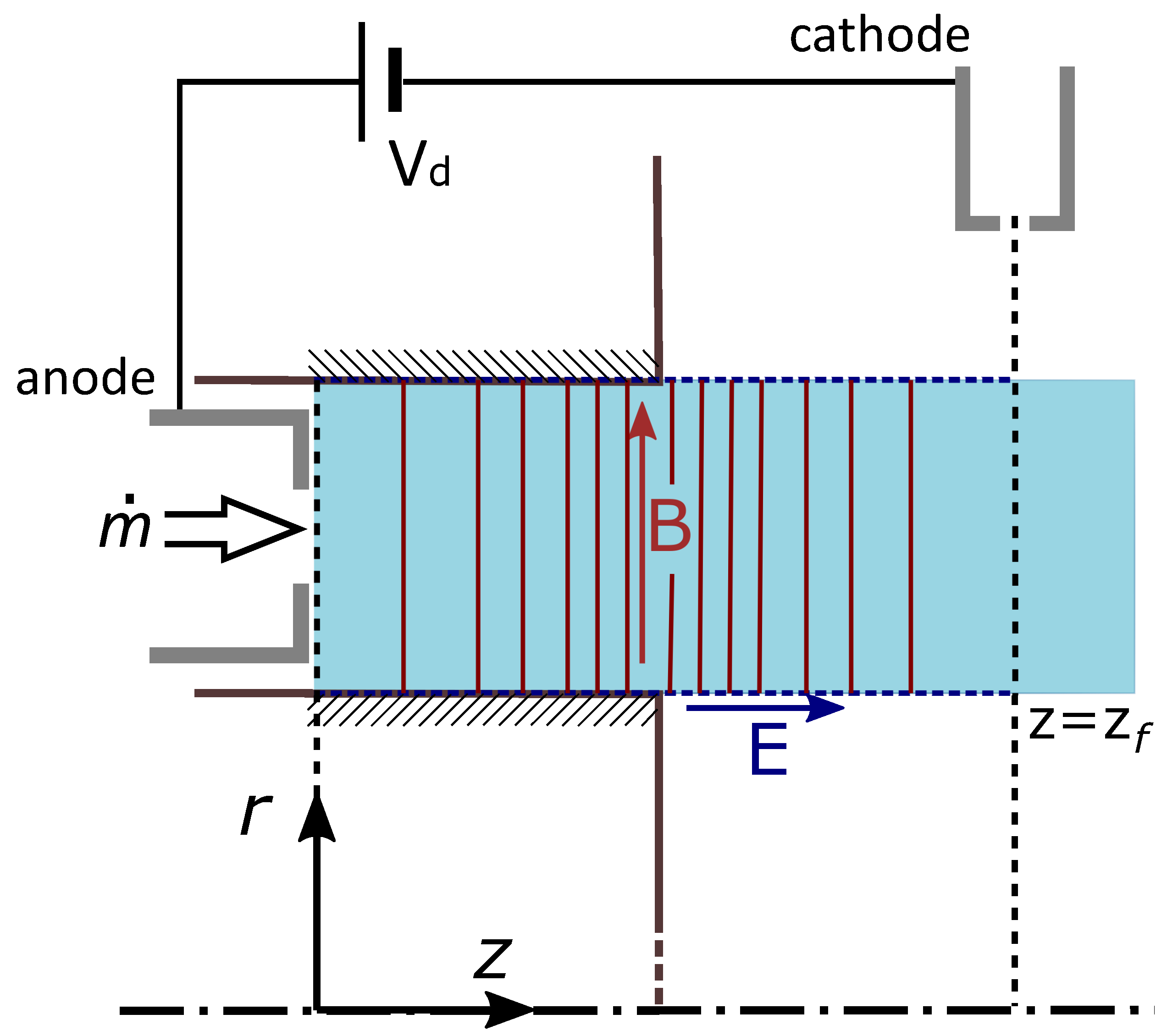
A fully-fluid unsteady 1D model is proposed here to describe the dynamics of the plasma discharge in the thruster. The plasma is assumed to be quasi-neutral and mainly composed of singly-charged ions. Three species are thus included in the model, namely electrons, singly-charged ions and neutrals. A drift-diffusion approximation is used to treat the electron flux. Ions are supposed isothermal and unmagnetized, and neutrals are assumed to have constant axial velocity (
) in the domain. Furthermore, the magnetic field is assumed to be purely radial. With reference to
Figure 1, the model is aimed at providing time-varying, averaged plasma properties over
z-sections inside the channel and in the near-plume, from the anode surface (
) up to a virtual line (
) where cathode boundary conditions are imposed. Part of the plume is included in the spatial computational domain of the model in order to provide some information also outside of the channel.
In the following, we concisely introduce the model equations dividing the discussion for each species included in the model. Since we are dealing with a 1D model, it is implicit that all the equations and quantities involved are averaged over z-sections.
2.1. Neutrals
Neutral atoms are assumed to have constant axial velocity
and constant temperature. Thus, only the continuity equation is included in the model as a classical linear transport/reaction equation with
constant and assigned among the problem input data:
where
and
are the number density of neutrals and electrons, respectively. As will be detailed later, plasma is assumed to be quasi-neutral, so that
where
is the ion number density. The term
in Equation (
1) is the ionization-rate coefficient of the neutral propellant atoms due to electron impact, and the product
is the corresponding ionization frequency. The ionization-rate coefficient
is a function of the electron internal energy
. More specifically, we use a tabulated version of
using collision cross section data from the
lxcat database [
56] and processed with the
Bolsig+ solver [
57] in order to obtain rates for a Maxwellian electron energy distribution function as a function of
.
In Equation (
1), the term
represents the neutral particles flowing in the domain from the lateral walls due to ion recombination. The model used to describe the plasma interaction with the channel walls and the expression for
is presented in detail in
Appendix A. Note that this term, as well as the other wall sink terms introduced in the electron momentum and energy equations (see
Section 2.3), is modulated through a wall interaction coefficient,
, that accounts for the uncertainties in the description of the plasma–wall interaction and is one of the calibration parameters that are used to fit the experimental reference data, as detailed later in
Section 2.5.
2.2. Ions
Ions are assumed to be isothermal with constant temperature
, which is assigned among the problem data. For this reason, only two scalar equations are included for the ion dynamics in the present 1D model, i.e., the continuity equation and momentum balance in the
z-direction. Indicating with
the ion velocity in the axial direction, the continuity equation writes as:
Note that the decrease in ion density outside the thruster channel due to the plume expansion (see, for instance, [
29]) is not taken into account here as it is not considered important in the dynamics of the low-frequency breathing mode, which is the main objective of the present analysis.
For the momentum balance in the
z-direction, we assume unmagnetized, collisionless ions, and the resulting equation writes as follows:
where
is the ion pressure,
is the ion mass and
is the electric potential (so that
is the component of the electric field in the
z-direction). We further specify that the ion pressure is related to the ion temperature, assuming an isotropic Maxwellian distribution for the random thermal ion velocity, thus leading to the ideal gas law:
where
is the Boltzmann constant. Note that in the momentum balance (
3) we have neglected momentum transfer due to charge exchange collisions, which are sometimes included in similar models in the literature (see, for instance, [
29]).
While the formulation presented above allows for a finite, albeit constant, ion temperature, the energy of the ion fluid is largely dominated by the kinetic component, and thermal effects are not considered to have a significant impact on the dynamics of breathing mode oscillations. Therefore, in the simulation results presented in
Section 4, the ions are assumed to be cold by setting
.
2.3. Electrons
The continuity equation for the electrons is identical to that of ions as a consequence of the quasi-neutral assumption, which implies the point-wise and instantaneous equality
:
where
is the electron velocity component in the axial direction. Since the characteristic length and time scales of the phenomena under investigation are much larger than the Debye length and of the inverse of the plasma frequency, and considering that the wall sheaths are excluded from the domain, the quasi-neutral assumption is well justified.
By subtracting the two conservation equations for ions and electrons, namely Equations (
2) and (
5), and multiplying by the electron charge
e, the current conservation equation is obtained:
Equation (
6) essentially states that the current density, defined as
is a funcion of the sole time, i.e.,
.
As concerns the momentum balance of the electrons, we use the drift-diffusion approximation, which implies that electrons are assumed to be at steady state within the characteristic evolutive time of ions, i.e., inertia terms are negligible in the momentum balance for electrons. This last assumption is consequent to the small ratio between electron and ion masses, i.e.,
, which implies a low-Mach number approximation for electrons, i.e., electrons move at a much lower velocity with respect to their thermal speed, and this is shown in detail in the asymptotic analysis proposed in [
58]. Finally, electrons are supposed to be magnetized, and the magnetic field is assumed to be purely radial, i.e.,
.
As a result, the momentum balance in the axial (
z) and azimuthal (
) directions becomes:
where
is the electron velocity component in the azimuthal direction and the coefficient
is the momentum transfer collision frequency. In the proposed model,
is given as the sum of several concomitant contributions. In particular:
where
is the electron–wall collision frequency, and
is a generic collision frequency taking into account all the collisions that electrons undergo with neutral atoms, including elastic, ionization and excitation collisions, whose values result from the product of the neutral density and the relevant reaction rate
, which were obtained using
Bolsig+ [
57] and cross section data extracted from the
lxcat database [
56]. The wall collision frequency
, which accounts for the electron momentum loss to the channel lateral walls, follows from the plasma–wall interaction model detailed in
Appendix A, and it is modulated with the wall interaction coefficient
, as previously discussed.
The anomalous collision frequency
is finally modeled to be proportional to the local cyclotron frequency of the electrons
using the classical expression:
where
is a free non-dimensional parameter among those included in the calibration (see
Section 2.5).
The momentum balance in the azimuthal direction, Equation (9), can be solved in terms of
and the result substituted in the axial balance (
8) so as to obtain a single equation in
:
The cross-field mobility
in the previous equation is defined as:
where
is the unmagnetized mobility and
is the Hall parameter. If we further assume that electron velocities follow an isotropic Maxwellian distribution of temperature
, the electron pressure
can be related to
as follows:
Thus, Equation (
12) becomes:
Unlike ions, the electron temperature is not constant and is among the unknowns of the problem. Thus, it is necessary to include the energy equation for electrons in the model. In particular, following Reference [
29], we consider here the internal energy equation for the electrons, obtained by subtracting the kinetic energy equation from the equation for the total electron energy. As a result, the contribution of the electron potential
disappears in the internal energy balance. Using the relation between internal energy and electron temperature for a Maxwellian distribution (
), the conservation of internal energy writes as follows:
In this equation, the term D is a diffusion term, the term H represents the conductive heat flow,
represents ionization and excitation losses, and
(which is also modulated with the wall interaction coefficient
) models the energy losses at the walls and is discussed in detail in
Appendix A. More specifically, the collisional energy loss
is expressed in terms of the collisional energy loss coefficient
K, which is a function of the electron energy. In the same way as the ionization rate,
values were extracted from the Biagi database [
56] and were calculated as a function of the electron temperature for a Maxwellian energy distribution using
Bolsig+ [
57].
2.4. Model Formulation and Numerical Discretization
The 1D model is based on the equations introduced in the previous sections, which are further manipulated as detailed here. The first manipulation carried out concerns the ion axial momentum Equation (
3). In particular, following the literature [
28], the electric potential in the equation is eliminated by means of Equation (
15), which gives:
This simplification enhances the numerical stability in the solution of the hyperbolic (inviscid) part of the ion equations, as amply demonstrated in the literature. The main reason is that the correct acoustic speed to consider in the hyperbolic part of the ion equations is the one of Equation (
17), i.e., the one related to the following equivalent sound speed
for ions:
A second manipulation of the equations consists in combining the expression for the current density, Equation (
7), and the electron momentum Equation (
12) and integrating over the entire domain to compute the discharge current density:
where we assumed
and where
is the potential difference between the first point of the investigated quasi-neutral domain (
) and the cathode (
). Specifically, if
is the total discharge voltage applied between anode and cathode,
takes into account the potential drop (
) that occurs in front of the anode sheath:
where
is the electron current density at the anode,
is the ion current density at the anode, and
is the current density associated with the electron thermal flux, assuming a Maxwellian distribution function at the anode sheath edge. The expression for the sheath potential drop of Equation (
21) follows a classical description of a charged electrode immersed in a plasma and is limited to zero since the sheath found in front of the anodes of Hall thrusters is considered to be electron repelling [
29].
Once
J is known (and thus the total discharge current
I by multiplication with the channel cross section area), the electron velocity can be deduced by charge conservation:
Finally, the electric potential can be computed, if needed, directly by using the electron momentum Equation (
15), as usual when working with the quasi-neutral plasma approximation.
The final system of equations is strongly coupled and non-linear. However, when semi-discretized in time following a line-method approach, i.e., thinking about a discrete-in-time advancement of the model, the following fractional step method is proposed to advance the equations from a generic time level to . Provided that all plasma quantities are known at time , sub-problems are identified and solved in consecutive order:
The first three subproblems above are governed by PDEs, and appropriate boundary conditions must be thus supplied, while boundary conditions on the potential are already included in the integral equation at point 4, as discussed above.
Subproblem 1 is a scalar transport equation with constant convection velocity
. Consequently, only one boundary condition on
is required, which is the neutral density specified at the anode, i.e., at
. This boundary condition is easily recovered by knowing the thruster channel cross section area (
A) and the total injected mass flow rate (
) at the operating point under investigation; considering also the ion recombination at the anode, the condition reads as:
Subproblem 2 is a hyperbolic system of two equations, thus a variable number of boundary conditions is needed at each of the two boundaries of the domain depending on the local characteristic velocities. In the simulations carried out here, the solutions are always supersonic at the outlet boundary (i.e., ), so that no boundary conditions are required on that point. Conversely, at the anode, the local characteristic velocities are such that there can be characteristic lines entering the domain. In particular, in order for the electron-repelling sheath to form at the anode, it is imposed that the ions must enter at the anode sheath edge with a velocity higher than or equal to the sound speed .
Subproblem 3 is an elliptic 1D problem, which thus requires two boundary conditions on , one per domain boundary. At the anode, the electron energy flux is specified through a classical analysis of an electron-repelling sheath in front of a biased electrode, and is set equal to , where the values of the plasma parameters at the sheath edge are approximated with those at the center of the first cell adjacent to the anode. At the cathode boundary, instead, a constant temperature of 2 eV is imposed.
Concerning the numerical solution of the model’s PDEs listed above, all of them are discretized in space using a finite-volume formulation. In particular, the neutral dynamics (point 1) are solved by a first-order upwind discretization. Ion dynamics (point 2), which is governed by a hyperbolic system of two equations/unknowns with a flux function satisfying the homogeneity property (see [
59]), is solved by the Steger–Warming [
60] flux vector splitting method. The same splitting method is used to impose characteristics-based boundary conditions on the system. The electron energy equation (point 3) is solved by a second-order finite-volume formulation with a central evaluation of gradients at the cell interfaces. Finally, the integral equation for the evaluation of current density (point 4) is carried out consistently with the finite-volume formulations adopted for the PDEs. Regarding time discretization, since the splitting of the whole coupled problem into the five consecutive subproblems described above is a first-order splitting in time, all subproblems are advanced in time by a first order Euler implicit/explicit scheme. The implicit scheme is used for the electron energy equation, while the remaining equations are advanced in time explicitly.
A six-core/12-thread i7-8750H CPU PC with 16 Gb of RAM and a solid state drive was used for the computation. Adopting the numerical scheme described above, the simulation time needed to compute 1 ms of the plasma dynamic was about 1310 s. Note that the code is not optimized, and there are ample margins of improvement in this respect.
2.5. Model Calibration
The model described in previous sections includes a number of calibration coefficients. These account for the unknowns in the physical description and allow to accommodate the simplifications introduced in the model. In detail, the three elements that are considered as calibration coefficients are: (i) the neutral velocity, , (ii) the wall interaction coefficient, , and (iii) the anomalous diffusion coefficient, , that can, in general, be a function of axial location, i.e., .
The uncertainties on the value of the neutral velocity
come from the absence of a detailed simulation of the flow injection and of the anode thermal behavior coupled with the assumption of a constant velocity across the domain. For what concerns the wall interaction coefficient
, a physical closure is avoided and the coefficient is retained in the model to account for the unresolved radial gradients in the plasma profiles and to counteract the uncertainties in the plasma–wall semiempirical descriptions (see
Appendix A). Moreover, the coefficient allows to decrease the plasma–wall interaction, simulating partial shielding of the channel walls from the plasma due to the local inclination of the magnetic field, e.g., eroded and end-of-life conditions, such as the case under investigation in the present study. Finally,
represents the impact on the electron mobility of plasma turbulence and azimuthal oscillatory modes [
1]. Following experimental and numerical investigations found in the literature [
28,
29,
32,
61],
was assumed to have two different values, inside and outside of the channel, with the outside anomalous coefficient significantly higher (by a factor of 100) than the inside one and with a smooth transition of variable steepness between the two.
The three parameters were progressively varied in order to allow the simulation results to match as closely as possible the experimental reference data. The overall discharge current signal was taken as the reference calibration quantity for the model. More in detail, while varying the calibration coefficients, when an oscillatory limit-cycle solution was found, the main parameters that were monitored and compared with experiments were: (i) the average, minimum and maximum value of the discharge current during the breathing mode cycle, (ii) the root mean square value of the oscillatory component of the discharge current signal and (iii) the dominant frequency component in the power spectral density of the discharge current signal.
4. Results and Discussion
The detailed analysis of the experimental measurements is beyond the scope of this discussion; the reader is invited to read the work of Giannetti et al. [
55] for additional details on the probe data. In the following, we focus on the simulation results obtained after model calibration, and on the comparison with the reference experimental data, highlighting the main physical phenomena that the model is capable of reproducing, as well as the main shortcomings.
In order to simulate the HT5k DM2 (M1) operation, the thruster salient features were imported into the model. These included the core geometrical properties of the channel, as well as the radial magnetic field profile along the channel centerline. Moreover, the xenon operating condition detailed in
Table 1 was imported as input data for what concerns the injected mass flow rate and the applied discharge voltage. Finally, the simulation spatial domain was set to extend from the anode surface up to a full channel’s length downstream of the exit section, i.e.,
, where cathode boundary conditions were applied. With the domain and all required inputs fixed, the model calibration procedure detailed in
Section 2.5 was followed to find the best combination of the three parameters
and
.
The best fit of the discharge current experimental data was found for
m/s,
, and
equal to 0.075 inside the channel and equal to 7.5 in the plume (keeping a ratio of 100 between the two).
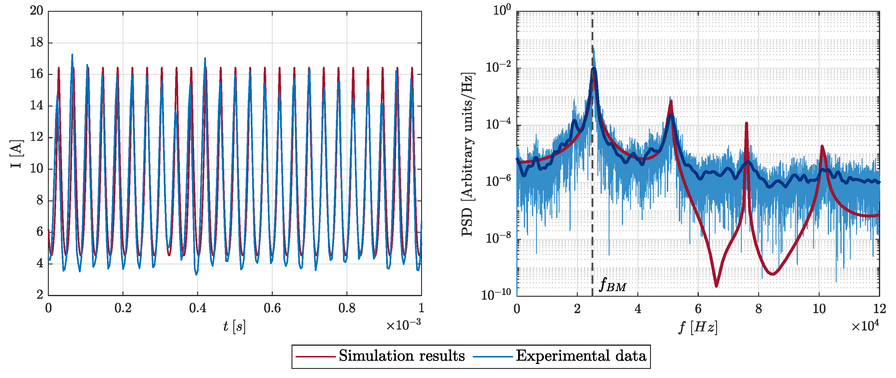
Figure 5 depicts a direct comparison between the discharge current measured by the oscilloscope during thruster testing and the discharge current predicted by the simulation of the operating point under investigation. Moreover,
Table 2 reports the quantitative comparison of the main parameters of the current signal that were monitored during calibration in order to obtain the best match between the simulations and the experiment.
The superposition of all main characteristics of the current signal is remarkable, with all control parameters exhibiting a relatively small difference between simulations and the reference experiment. This is strong evidence that the proposed numerical model incorporates all the necessary physics to correctly reproduce the core mechanism of breathing mode oscillations.
The neutral speed is typically linked to the anode temperature since the flow is considered sonic at injection. Following the accommodation coefficients discussed in [
43], typical anode temperatures found in Hall thrusters translate to typical neutral injection speeds in the 100 to 300 m/s range. Therefore, the value of
required to match the experimental results is relatively high. During the calibration process, it was found that the value of the neutral velocity has a direct impact on the dominant frequency of the discharge current oscillations when present. This is coherent with an intuitive understanding of breathing mode as an ionization instability: if the neutral speed increases, the time needed by the neutral flow to reach the high temperature region decreases and, thus, the plasma surges become more frequent. Since the experimental data presented a relatively high dominant frequency (see
Table 2), a correspondingly high neutral speed was needed. Relaxing the assumption of constant neutral velocity over the domain, and thus solving the neutrals momentum equation, could result in calibrated injection speeds more in line with expectations.
For what concerns the wall interaction correction factor
, a significant reduction of the particle flow to the walls, when compared to that predicted by classical models, was needed to correctly reproduce the experimental results, and especially to match the total oscillation amplitude. This trend was expected, in part, since the radial gradients of the plasma properties are not resolved in the current model, and the plasma density is bound to decrease towards the walls due to the ion acceleration in the pre-sheath region. Moreover, a significant uncertainty exists in the representativeness of fluid sheath models, such as the one described in
Appendix A, which, according to multiple studies, tend to overestimate the wall losses [
70,
71]. A further justification lies in the specific configuration of the thruster model under investigation. As described in
Section 3.1, the M1 version of the HT5k DM2 thruster was designed to mimic end-of-life conditions of the Hall thruster, with a chamfer at the end of the ceramic channel that diminishes the local incidence angle of the magnetic field lines on the channel walls. As demonstrated in the literature [
38,
72,
73], this can effectively produce a shielding effect of the channel walls from the plasma. It is not possible to reproduce this feature in a 1D model in which magnetic field lines are assumed to be radial and orthogonal to the channel walls, but this is reflected in the reduction of the wall interaction coefficient
.
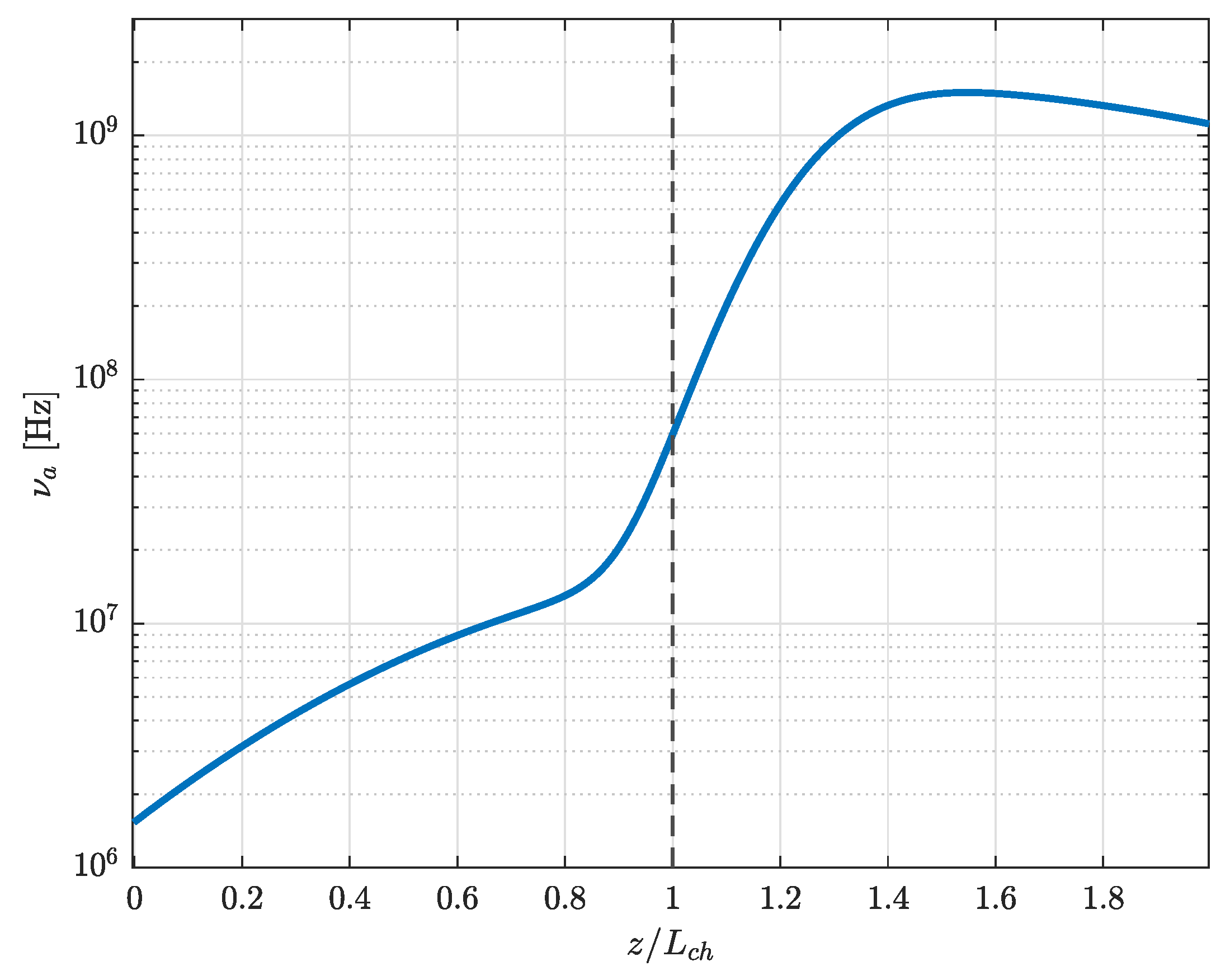
Finally, it was found that the anomalous collisionality parameter
has a strong impact on the dynamic behavior of the solution. Particularly, slight variation in the anomalous diffusion parameter, especially inside the channel, implied significant differences in both the average current value and the amplitude of the oscillations. A similar trend was also observed by Hara et al. in [
29]. Interestingly, also the steepness of the transition in the anomalous diffusion coefficient profile from the inside value to the outside one was found to have a significant influence on the oscillation dynamics. The resulting profile of the anomalous collision frequency is presented in
Figure 6.
It is worth noting how this profile recovers values of the anomalous collisionality close to the ones obtained by other authors and calibrated on experimental data [
29,
46,
61].
With the model now calibrated on the experimental profile of the discharge current, it is possible to investigate the dynamics of all intensive plasma properties predicted by the simulations in the channel and near-plume.
Figure 7 and
Figure 8 depict the evolution of all unknowns of the system over the entire
plane for a simulated time of 0.2 ms.
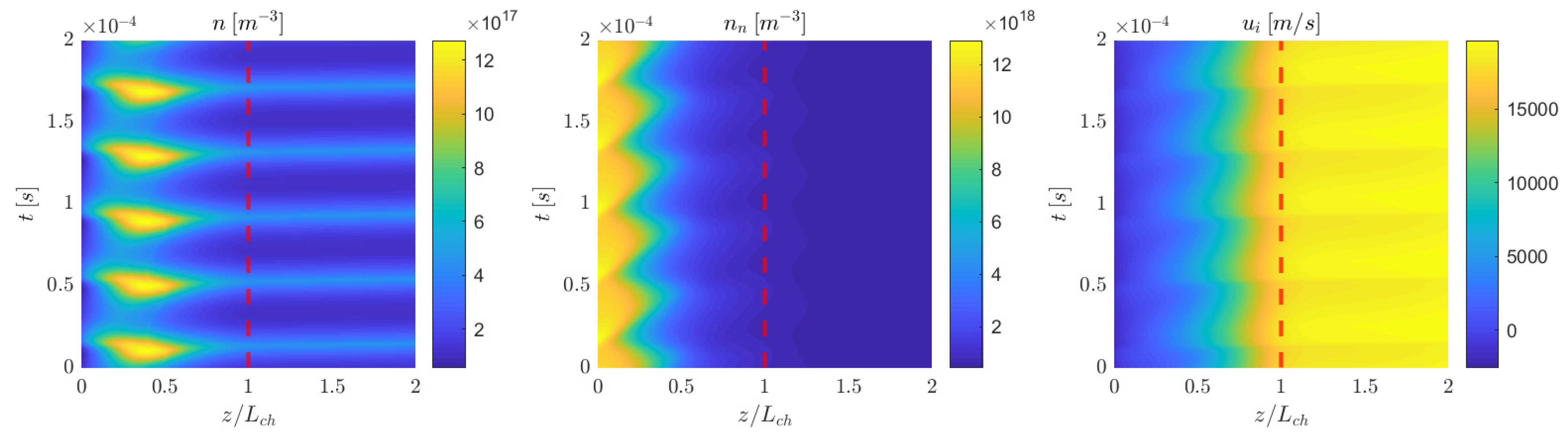
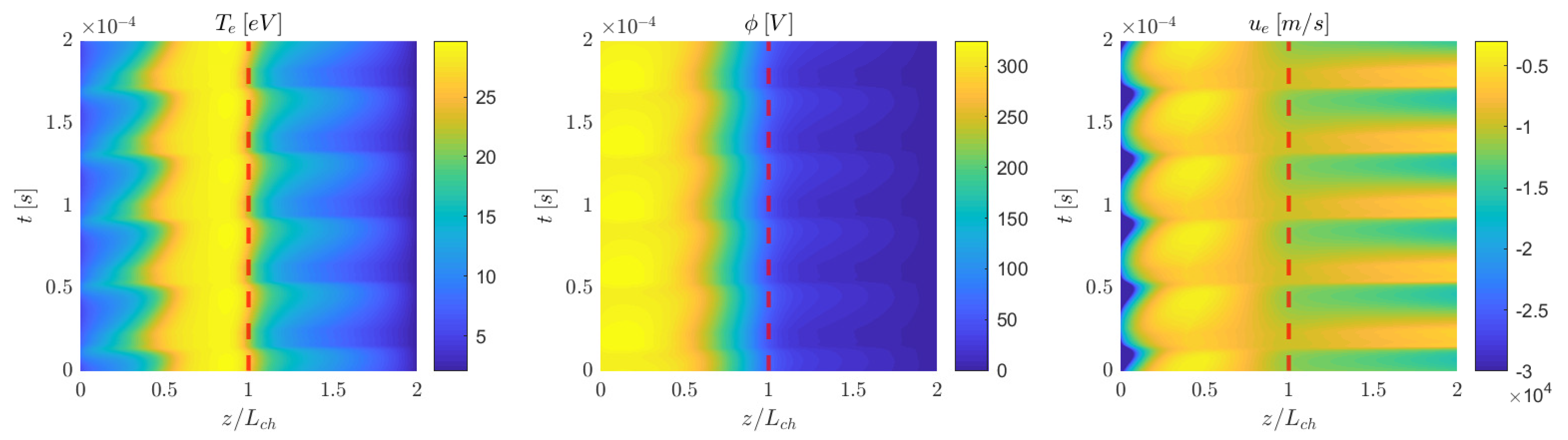
Figure 7 details the dynamics of the heavy species (ions and neutrals), while
Figure 8 reports the behavior of the properties related to the electron equations.
The results give a striking picture of the effects of breathing mode oscillations on the plasma. Neutral atoms are generated at the anode boundary through the mass flow injection of propellant. They move through the channel (see diagonal lines in
Figure 7 (middle)) until they reach a region with a sufficiently high electron temperature and density to achieve effective ionization. At this point, a surge of plasma density occurs in the channel, indicated by the periodic density peaks of
Figure 7 (left). This dynamic exchange between neutrals and plasma is very clear in the near anode region, where the plasma density and neutral density oscillations are almost in phase opposition. The newly generated high-density plasma is then moved by the electric field both downstream, exiting the thruster at high speed, and upstream towards the anode, where a weak reversed electric field is established to counteract the local electron pressure and ensure the anode sheath boundary conditions are respected. This ion backflow recombines at the anode, increasing the local neutral density and further fueling the breathing mode feedback mechanism, before the cycle starts again. Observing that the oscillations are found for all properties over the whole plasma domain with the same characteristic frequency validates the interpretation of breathing mode as a global self-sustained instability. The same picture was deduced from the experimental results of [
55] where a wavelet analysis of the measurements was performed over the probed region.
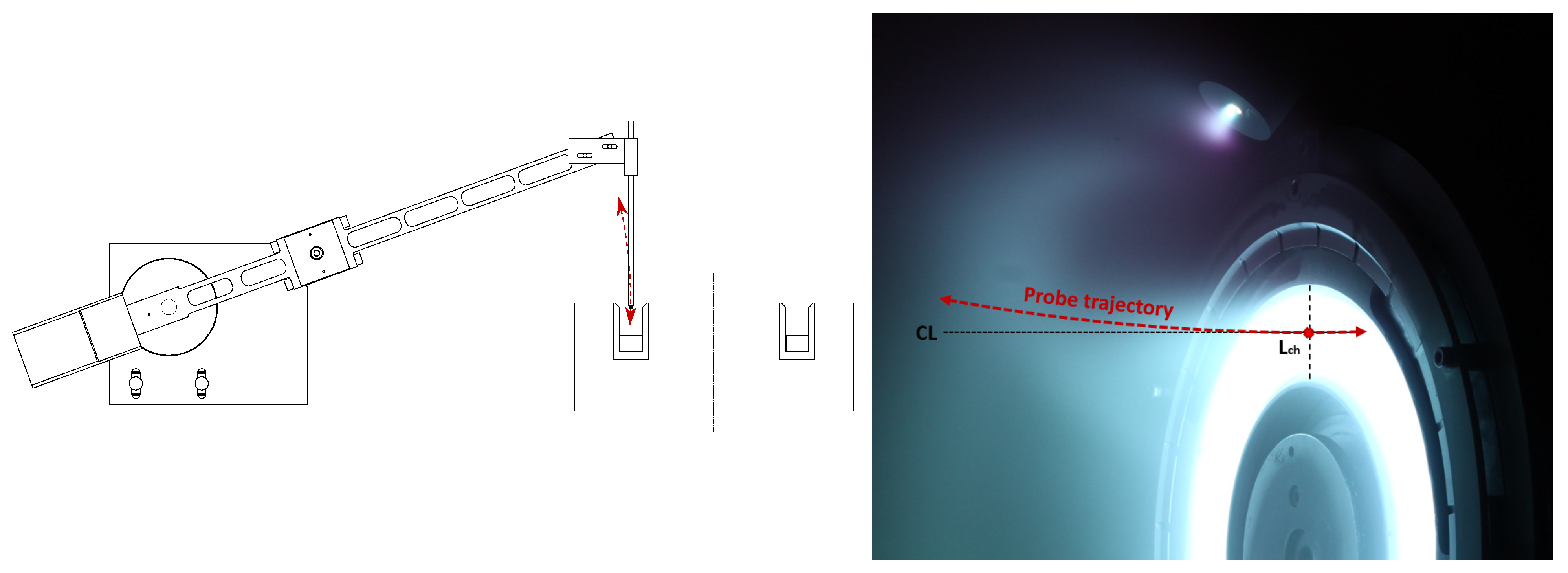
The measurements performed and the data processing technique presented in [
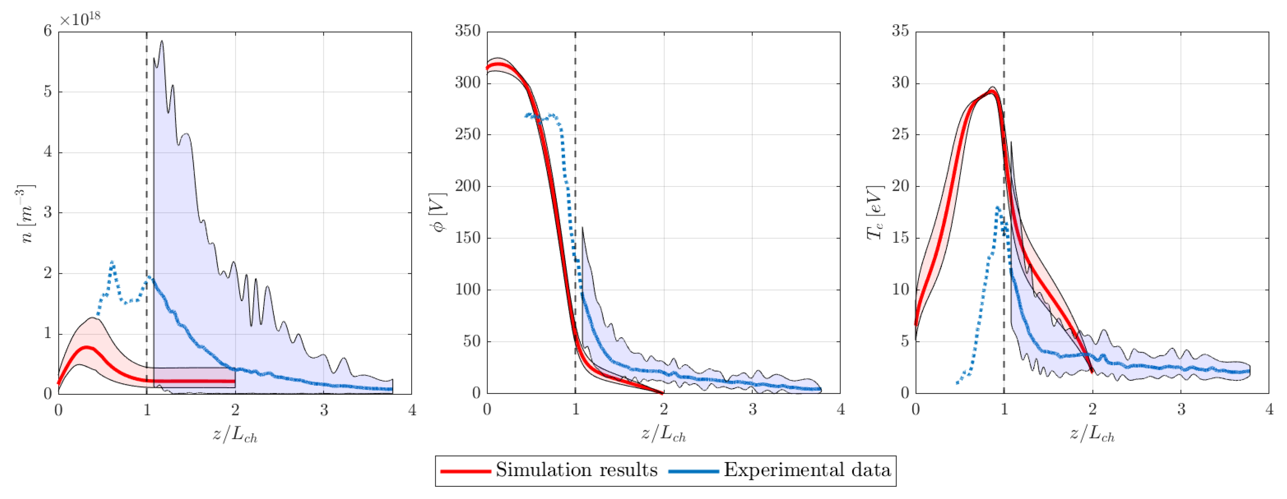
55] allowed the reconstruction of local oscillations of plasma density, potential and electron temperature in a region spanning from 15 mm upstream of the thruster exit plane up to 70 mm downstream. Although the domain investigated with the simulations was limited to just one channel length downstream of the channel exit section, it is interesting to compare the local measurements of the plasma properties with the results of the simulation in order to understand the degree of accuracy achieved by the adopted formulation in the reconstruction of the local plasma behavior after calibration on the sole discharge current signal. This comparison is presented in
Figure 9, where the experimental oscillations are reported only for the region where the probe was not perturbing the plasma flow (
mm). It should be noted that the plasma potential measurements refer to the voltage difference between plasma and ground, while the simulations are relative to the cathode plasma potential, therefore, the comparison is only quantitatively valid neglecting the cathode reference potential.
The order of magnitude of all relevant properties and the general trend of the profiles and oscillations over the probed domain is successfully reconstructed by the simulations: the plasma density average value and oscillation amplitude is higher closer to the anode and decreases moving away from the thruster exit plane, the potential drop is mostly concentrated in the high magnetic field region of the thruster, close to the channel exit. Consequently, the highest value of the electron temperature is found in the same region. The numerical model also manages to simulate the oscillation of the acceleration region during the breathing cycle, with the fraction of potential drop happening outside of the channel varying during the oscillation period.
Two major differences are found between the measurements and the simulation results. First, the plasma density average value and oscillation amplitude seem to be underestimated by the code in the near-plume region. The numerical results predict the peak of plasma density inside the channel, further upstream with respect to the measurements. Second, the predicted temperature profile, and especially the peak value, is higher than the measurements, even though the peak is in a region where the measurements may be in part affected by the perturbations induced by the probe. The adopted formulation appears to overestimate the electron temperature and to move the acceleration region more inside the channel with respect to the empirical evidence. For what concerns the density profile, the neutral back ingestion from the chamber and from the cathode during testing could supply additional slow particles in the near-plume region. In general, the discrepancies observed between numerical results, and experimental data are also tied to the core assumptions of the simplified model. First, the code presents values averaged over z-sections of the channel, while the measurements refer to the local values on the channel centerline. Moreover, the plume expansion is not modeled in detail in the simulations, leading to potential local inaccuracies in the representation of the plasma dynamics downstream of the channel exit. Considering the strong sensitivity of the local plasma parameters to the calibration coefficients, both discrepancies are also linked with the specific profile of the anomalous collisionality that we have selected and with the value of and needed to match the current profile, but are also a consequence (at least partially) of the application of a 1D axial formulation to an end-of-life configuration, as previously discussed.
It is worth mentioning that, in general, the plasma turbulence effect on electron transport is a function of the local plasma properties (see, for example, Reference [
74]) that vary during the breathing mode cycle. Therefore,
could also be a function of time, i.e.,
. While we have decided to fix the axial profile of the anomalous collisionality to limit the degrees of freedom in the model calibration, experimental investigations in the literature [
46] have highlighted how
varies significantly during the breathing mode cycle.
The adoption of a time-varying profile for the anomalous diffusion coefficient could allow for a closer representation of the experimental results within the boundaries of the presented formulation and will be the subject of future investigations.
5. Conclusions
In this paper, we have presented a synergic experimental/numerical investigation of the breathing mode in a 5 kW-class Hall thruster. In particular, we have shown the potential of using an informed 1D fully-fluid model of the plasma flow as a complementary tool with respect to the experiments. On the basis of available measurements, the current signal in particular, the model is aimed at estimating evolving plasma properties that are difficult to measure. Thanks to the availability of a detailed experimental database, which has been collected using a diagnostic technique based on the use of a fast-diving triple Langmuir probe, we have provided here an assessment of the prediction capabilities of the calibrated model.
More specifically, the model was set up to simulate one operating point of the HT5k and calibrated to reproduce the measured discharge current profile. Three calibration parameters implemented in the numerical description allowed to properly tune the model to the experimental observations: (i) the neutral injection velocity, (ii) the wall interaction coefficient and (iii) the anomalous diffusion profile. Following calibration, the discharge current profile predicted by the simulation closely matched the experimental results, exhibiting relatively small differences on all control metrics. This promising result confirms the capabilities of the adopted numerical description to reproduce the core mechanism of breathing mode oscillations.
The time evolution of the main plasma properties predicted by the calibrated simulations over the entire domain was presented and discussed, highlighting the dynamics of the longitudinal oscillation and its underlying global and self-sustained nature.
Finally, the measurements obtained for the plasma density, potential and electron temperature oscillations in the near-plume were compared to the numerical results. The model successfully managed to recreate the order of magnitude and overall trend of the properties’ profiles. Nevertheless, the simulations underestimated the values of density, overestimated the electron temperature, and predicted the acceleration region to be further upstream with respect to the experimental results.
Overall, the adopted approach of informing a reduced-order numerical description of the plasma dynamics with high-frequency measurements of the discharge current has demonstrated to be a promising path to gather additional insight on the dynamics of oscillatory modes in Hall thrusters. The possibility of comparing the simulation results with measurements of the local plasma properties represents a unique framework for the identification of the main physical processes that are needed to model the discharge of Hall thrusters. Future investigations will explore the application of the described approach to other thruster configurations and operating conditions, focusing on the adoption of a time varying profile of the anomalous diffusion and on the inclusion of the effects of the magnetic field topology in the model. Since experimental measurements of the discharge current are often easily available from the functional characterization of a Hall thruster, the proposed combined numerical-experimental approach may represent an important step toward the understanding of the characteristic physical processes of Hall thruster discharges.


 ,
, 


