
Innovative Mechanical Design Strategy for Actualizing 80 kg-Class X-Band Active SAR Small Satellite of S-STEP

 ,
, 
Abstract
1. Introduction
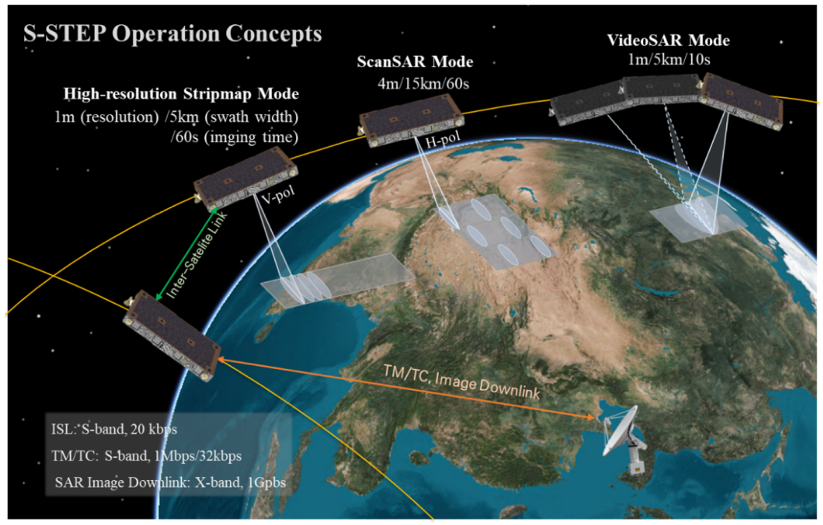
2. S-STEP System Overview
3. Innovative Mechanical Design for S-STEP
3.1. Development Philosophy
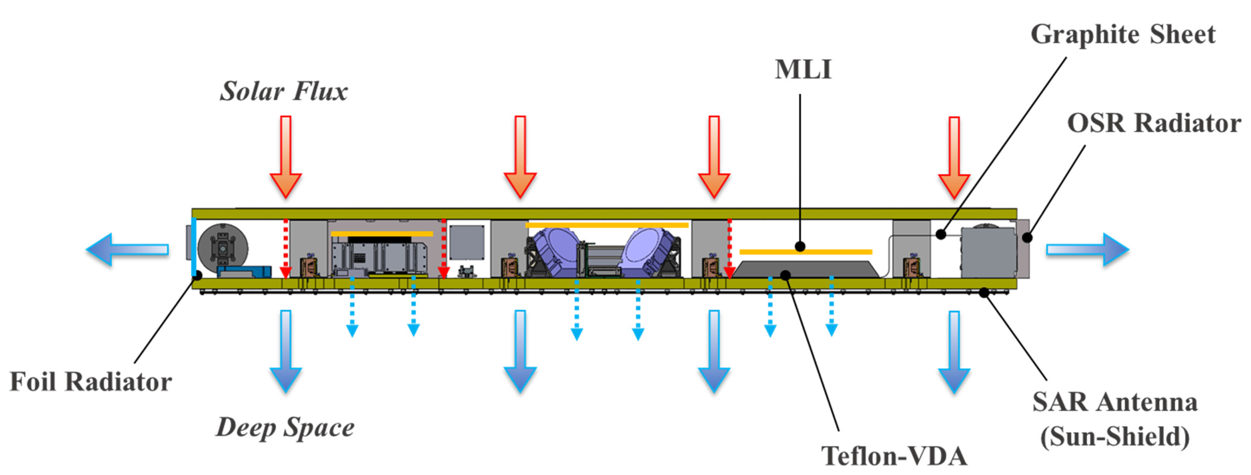
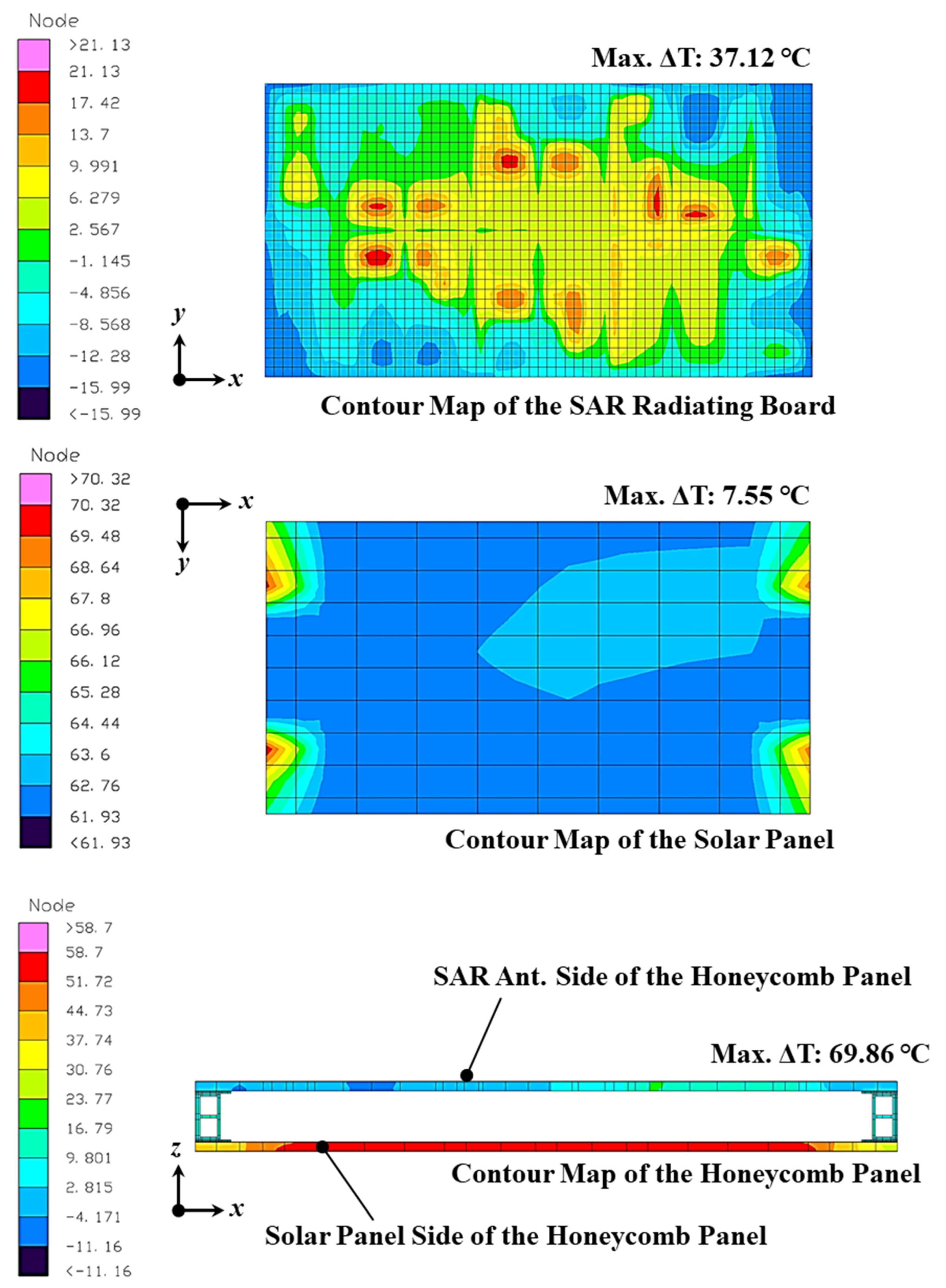
3.2. Thermo-Mechanical Design
4. Structural Analysis for S-STEP
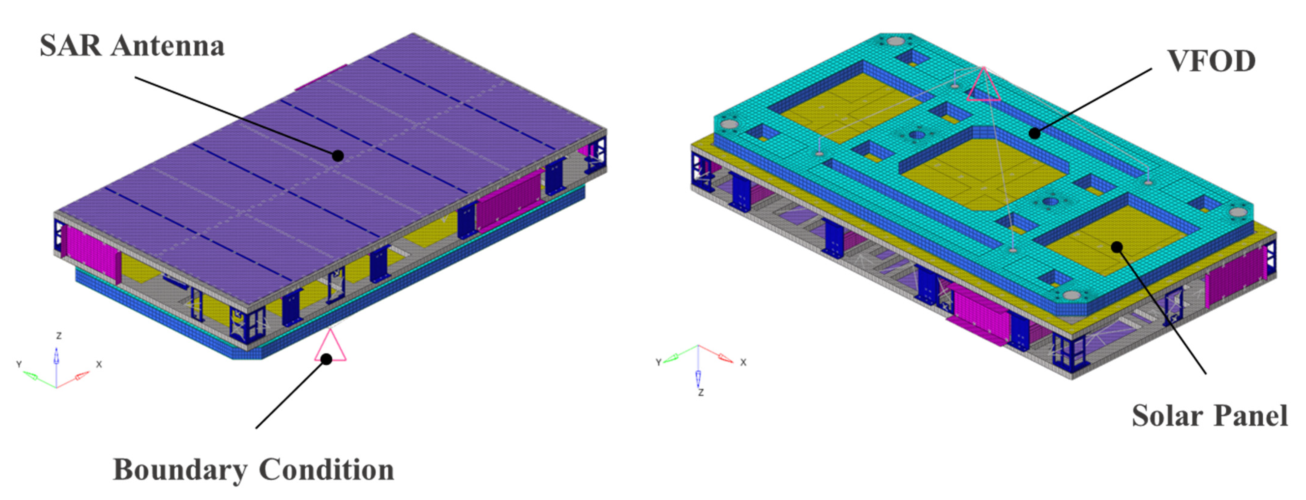
4.1. Structural Analysis Overview
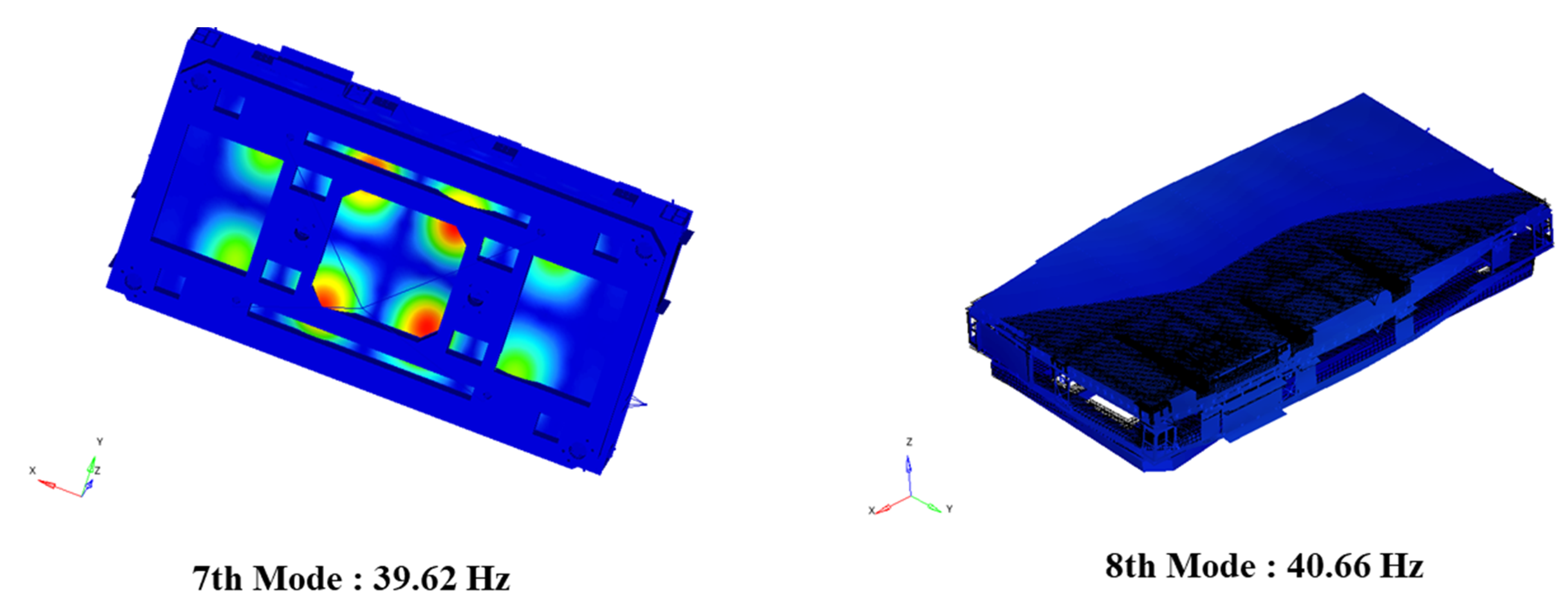
4.2. Structural Analysis Result
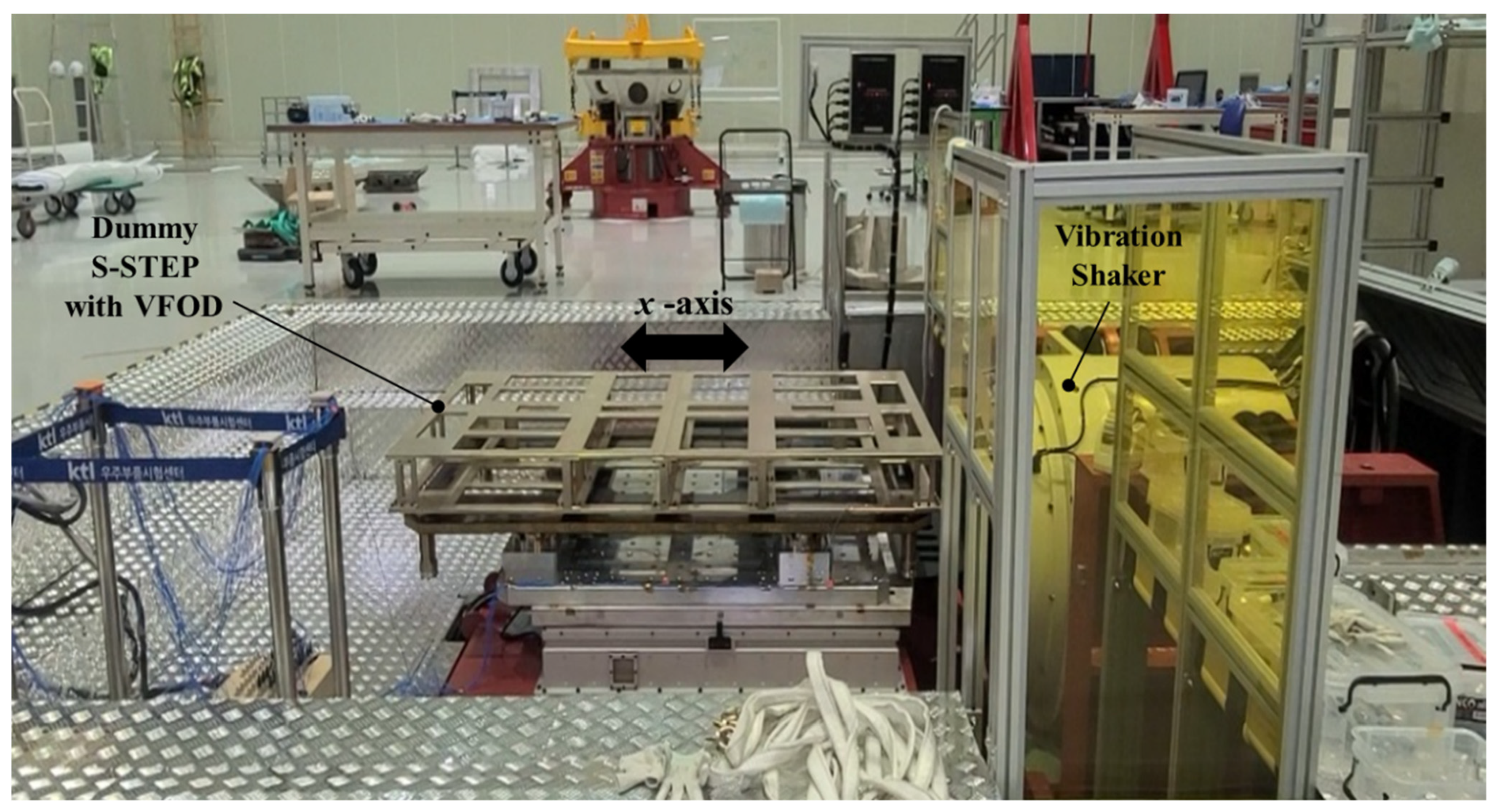
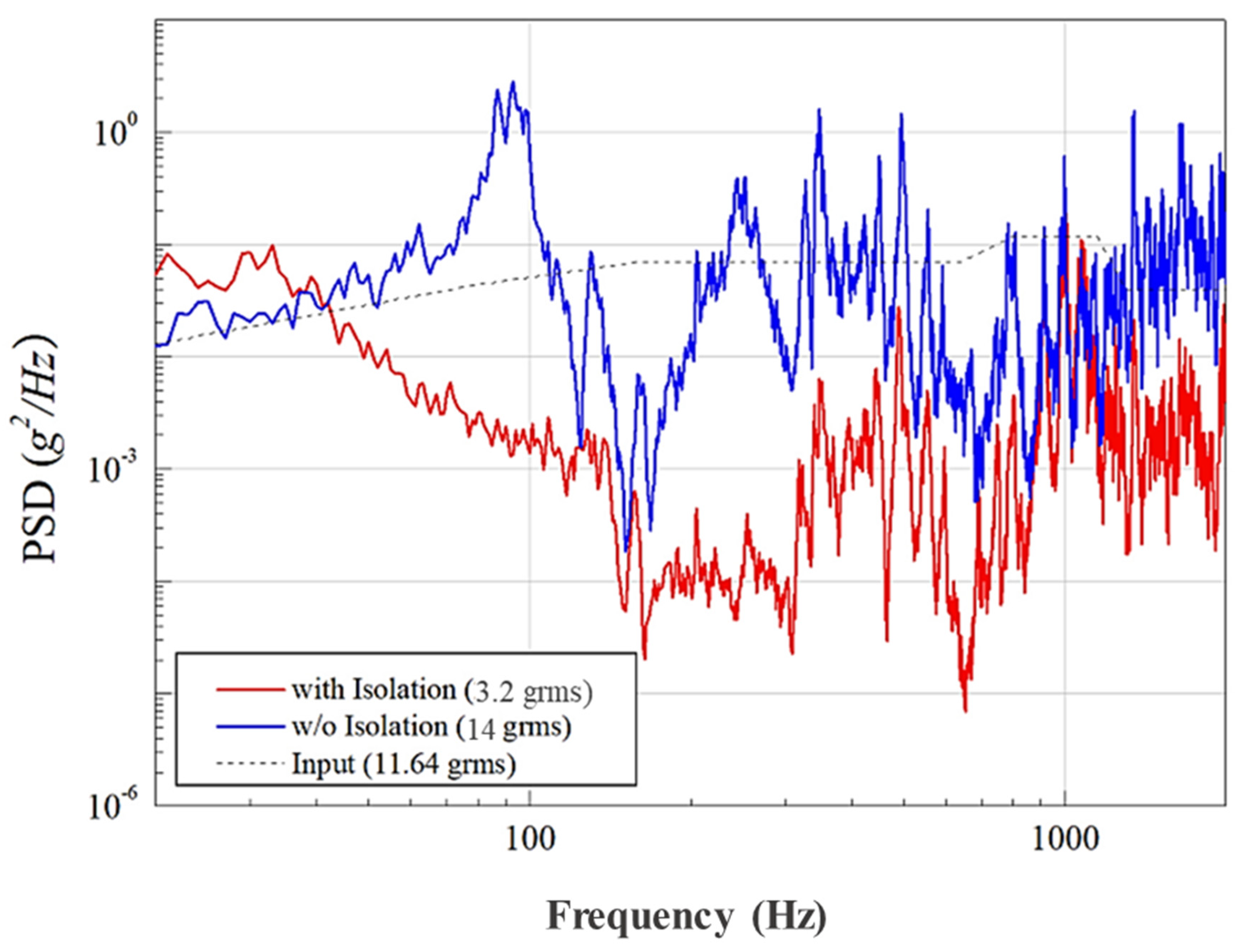
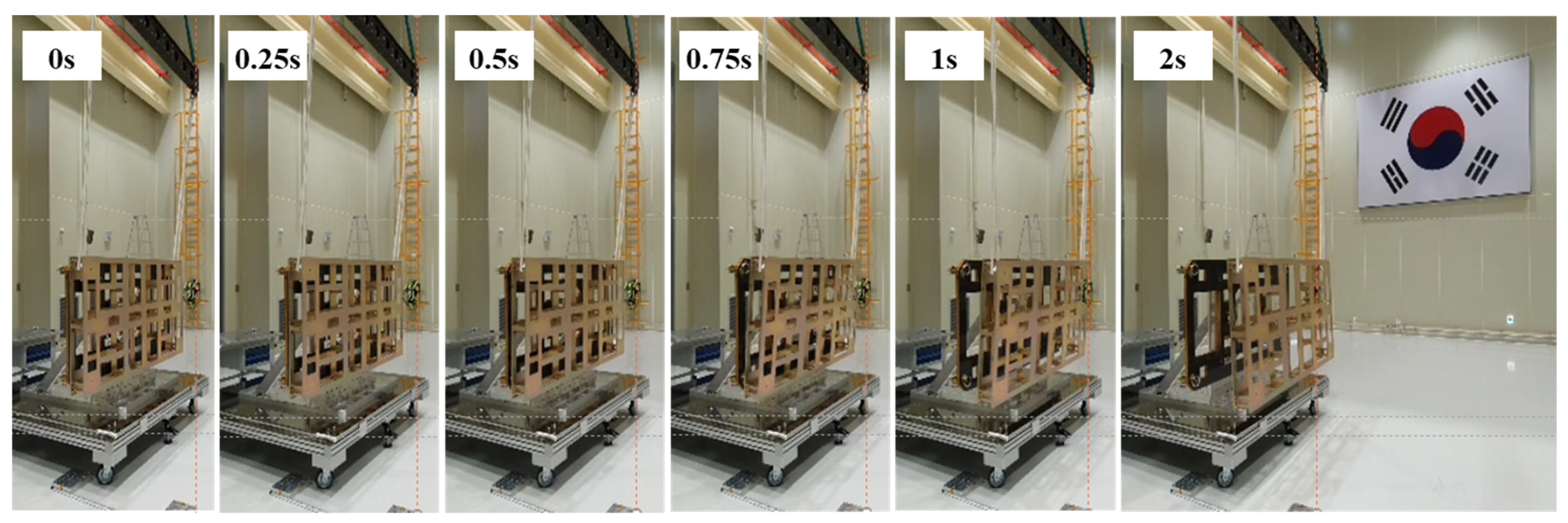
5. Development Test for Key Strategy
5.1. Development Test Overview
5.2. Development Test Result
6. Conclusions
Author Contributions
Funding
Data Availability Statement
Conflicts of Interest
References
- Howard, E.M. Faster, Better, Cheaper: Low-Cost Innovation in the U.S. Space Program; The Johns Hopkins University Press: Baltimore, MD, USA, 2003. [Google Scholar]
- Sweeting, M.N. Modern Small Satellites-Changing the Economics of Space. Proc. IEEE 2018, 106, 343–361. [Google Scholar] [CrossRef]
- Ince, F. Nano and micro satellites as the pillar of the “new space” paradigm. J. Aeronaut. Space Technol. 2020, 13, 207–221. [Google Scholar]
- Kuze, A.; Suto, H.; Nakajima, M.; Hamazaki, T. Thermal and near infrared sensor for carbon observation Fourier-transform spectrometer on the Greenhouse Gases Observing Satellite for greenhouse gases monitoring. Appl. Opt. 2009, 48, 6716–6733. [Google Scholar] [CrossRef] [PubMed]
- Available online: https://www.gminsights.com (accessed on 7 March 2021).
- Available online: https://www.synspective.com (accessed on 7 March 2021).
- Farquharson, G.; Woods, W.; Stringham, C.; Sankarambadi, N.; Riggi, L. The Capella Synthetic Aperture Radar Constellation. In Proceedings of the IGARSS 2018–2018 IEEE International Geoscience and Remote Sensing Symposium, Valencia, Spain, 22–27 July 2018; pp. 1873–1876. [Google Scholar]
- Available online: https://www.i-qps.net (accessed on 7 March 2021).
- Ignatenko, V.; Laurila, P.; Radius, A.; Lamentowski, L.; Antropov, O.; Muff, D. ICEYE Microsatellite SAR Constellation Status Update: Evaluation of First Commercial Imaging Modes. In Proceedings of the IGARSS 2020–2020 IEEE International Geoscience and Remote Sensing Symposium, Waikoloa, HI, USA, 26 September–2 October 2020; pp. 3581–3584. [Google Scholar]
- Covello, F.; Battazza, F.; Coletta, A.; Lopinto, E.; Fiorentino, C.; Pietranera, L.; Valentini, G.; Zoffolia, S. COSMO-SkyMed an existing opportunity for observing the Earth. J. Geodyn. 2010, 49, 171–180. [Google Scholar] [CrossRef]
- Morena, L.C.; James, K.V.; Beck, J. An introduction to the RADARSAT-2 mission. Can. J. Remote. Sens. 2004, 30, 221–234. [Google Scholar] [CrossRef]
- Torres, R.; Snoeij, P.; Geudtner, D.; Bibby, D.; Davidson, M.; Attema, E.; Potin, P.; Rommen, B.; Floury, N.; Brown, M.; et al. GMES Sentinel-1 mission. Remote Sens. Environ. 2012, 120, 9–24. [Google Scholar] [CrossRef]
- Zhou, F.; Yang, J.; Jia, L.; Yang, X.; Xing, M. Ultra-High Resolution Imaging Method for Distributed Small Satellite Spotlight MIMO-SAR Based on Sub-Aperture Image Fusion. Sensors 2021, 21, 1609. [Google Scholar] [CrossRef] [PubMed]
- Sun, D.; Dou, W.; You, L.; Yan, X.; Shen, R. A Broadband Proximity-Coupled Stacked Microstrip Antenna With Cavity-Backed Configuration. IEEE Antennas Wirel. Propag. Lett. 2011, 10, 1055–1058. [Google Scholar] [CrossRef]
- Wijker, J.J. Spacecraft Structures; Springer Science and Business Media: New York, NY, USA, 2008. [Google Scholar]
- European Space Community. Space Engineering: Spacecraft Mechanical Loads Analysis Handbook; ECSS Secretariat ESA-ESTEC: Noordwijk, The Netherlands, 2013; ECSS-HB-32-26A. [Google Scholar]
- Jun, Z.; Hongxing, H.; Zhiyi, Z. An evaluation of the whole-spacecraft passive vibration isolation system. Proc. Inst. Mech. Eng. Part G J. Aerosp. Eng. 2007, 221, 67–72. [Google Scholar] [CrossRef]
- Johnson, C.D.; Wilke, P.S.; Pendleton, S.C. SoftRide vibration and shock isolation systems that protect spacecraft from launch dynamic environments. In Proceedings of the 38th Aerospace Mechanisms Symposium, Williamsburg, Virginia, 17–19 May 2006. [Google Scholar]
- Available online: https://www.csaengineering.com (accessed on 20 March 2021).
- Available online: https://www.spacex.com (accessed on 20 March 2021).
- Ping, L.; David, N.; Shelly, S.; Kenneth, H.; John, S. Pitch-over maneuver and guidance for rocket-back boosters. AIAA Guidance. In Proceedings of the Navigation and Control Conference, Portland, OR, USA, 8–11 August 2011. [Google Scholar]
- Available online: https://www.arianespace.com (accessed on 20 March 2021).
- Available online: https://www.kosmotras.ru (accessed on 20 March 2021).
- Available online: https://www.jaxa.jp (accessed on 20 March 2021).
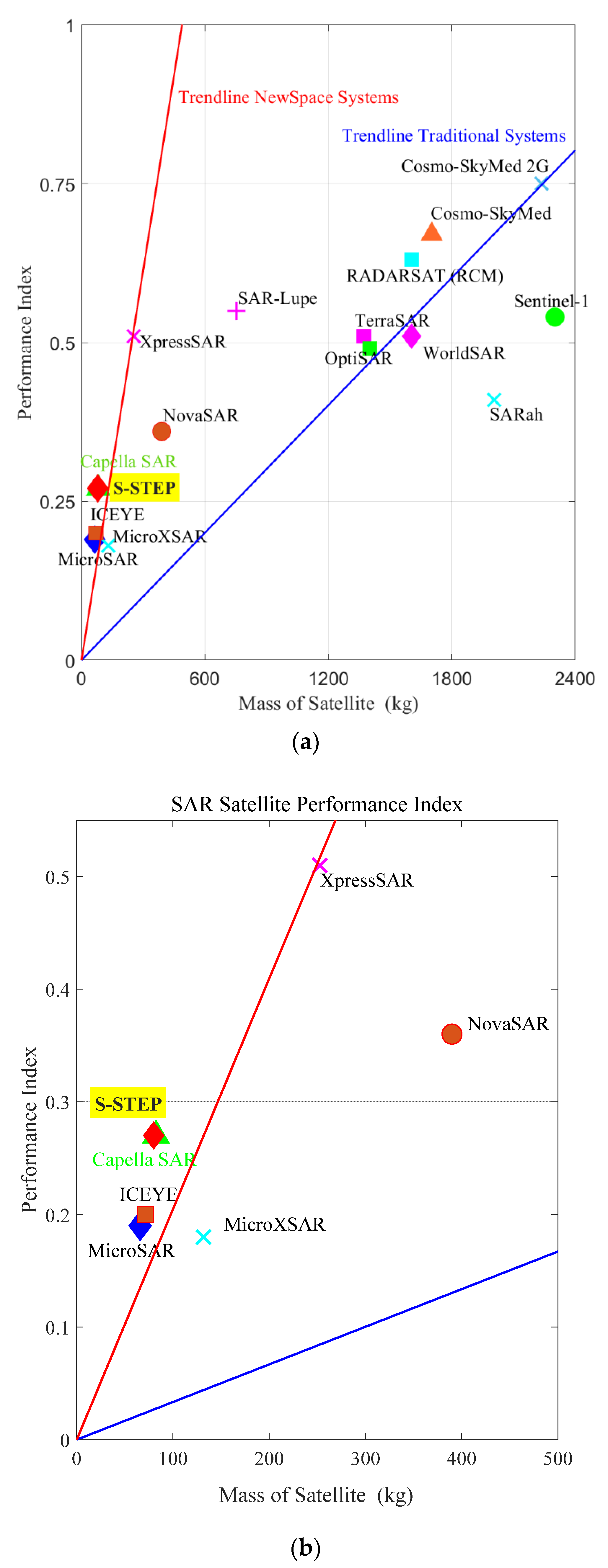
- Filippazzo, G.; Dinand, S. The potential impact of small satellite radar constellations on traditional space systems. In Proceedings of the 5th Federated and Fractionated Satellite Systems Workshop, Toulouse, France, 2–3 November 2017. [Google Scholar]
- Park, T.-Y.; Oh, H.-U. New PCB strain-based structural design methodology for reliable and rapid evaluation of spaceborne electronics under random vibration. Int. J. Fatigue 2021, 146, 106147. [Google Scholar] [CrossRef]
- Steinberg, D.S. Vibration Analysis for Electronic Equipment, 3rd ed.; Wiley-interscience: Hoboken, NJ, USA, 2000. [Google Scholar]
- Kwon, S.-C.; Jo, M.-S.; Ko, D.-H.; Oh, H.-U. Viscoelastic multilayered blade-type passive vibration isolation system for a spaceborne cryogenic cooler. Cryogs 2020, 105, 102982. [Google Scholar] [CrossRef]
- Available online: https://www.ebad.com (accessed on 25 March 2021).
- Available online: http://www.everlubeproducts.com (accessed on 25 March 2021).
- Available online: https://www.orbcomm.com (accessed on 25 March 2021).
- Park, D.; Miyata, K.; Nagano, H. Thermal design and validation of radiation detector for the ChubuSat-2 micro-satellite with high-thermal-conductive graphite sheets. Acta Astronaut. 2017, 136, 387–394. [Google Scholar] [CrossRef]
- Shukla, K.N. Heat Pipe for Aerospace Applications—An Overview. J. Electron. Cool. Therm. Control. 2015, 5, 1–14. [Google Scholar] [CrossRef]
- Miles, J.W. On structural fatigue under random loading. J. Aeronaut. Sci. 1954, 21, 753–762. [Google Scholar] [CrossRef]
- Park, T.-Y.; Kim, S.-Y.; Yi, D.-W.; Jung, H.-Y.; Lee, J.-E.; Yun, J.-H.; Oh, H.-U. Thermal Design and Analysis of Unfurlable CFRP Skin-Based Parabolic Reflector for Spaceborne SAR Antenna. Int. J. Aeronaut. Space Sci. 2021, 22, 433–444. [Google Scholar] [CrossRef]
- Kwon, S.-C.; Jo, M.-S.; Oh, H.-U. Experimental Validation of Fly-Wheel Passive Launch and On-Orbit Vibration Isolation System by Using a Superelastic SMA Mesh Washer Isolator. Int. J. Aerosp. Eng. 2017, 2017, 1–16. [Google Scholar] [CrossRef]
- Capece, P. Active SAR Antennas: Design, Development, and Current Programs. Int. J. Antennas Propag. 2009, 2009, 1–11. [Google Scholar] [CrossRef]
- Available online: http://www.nasa.gov (accessed on 25 March 2021).


| Specification | Value | |
|---|---|---|
| Mission Lifetime | 3 years | |
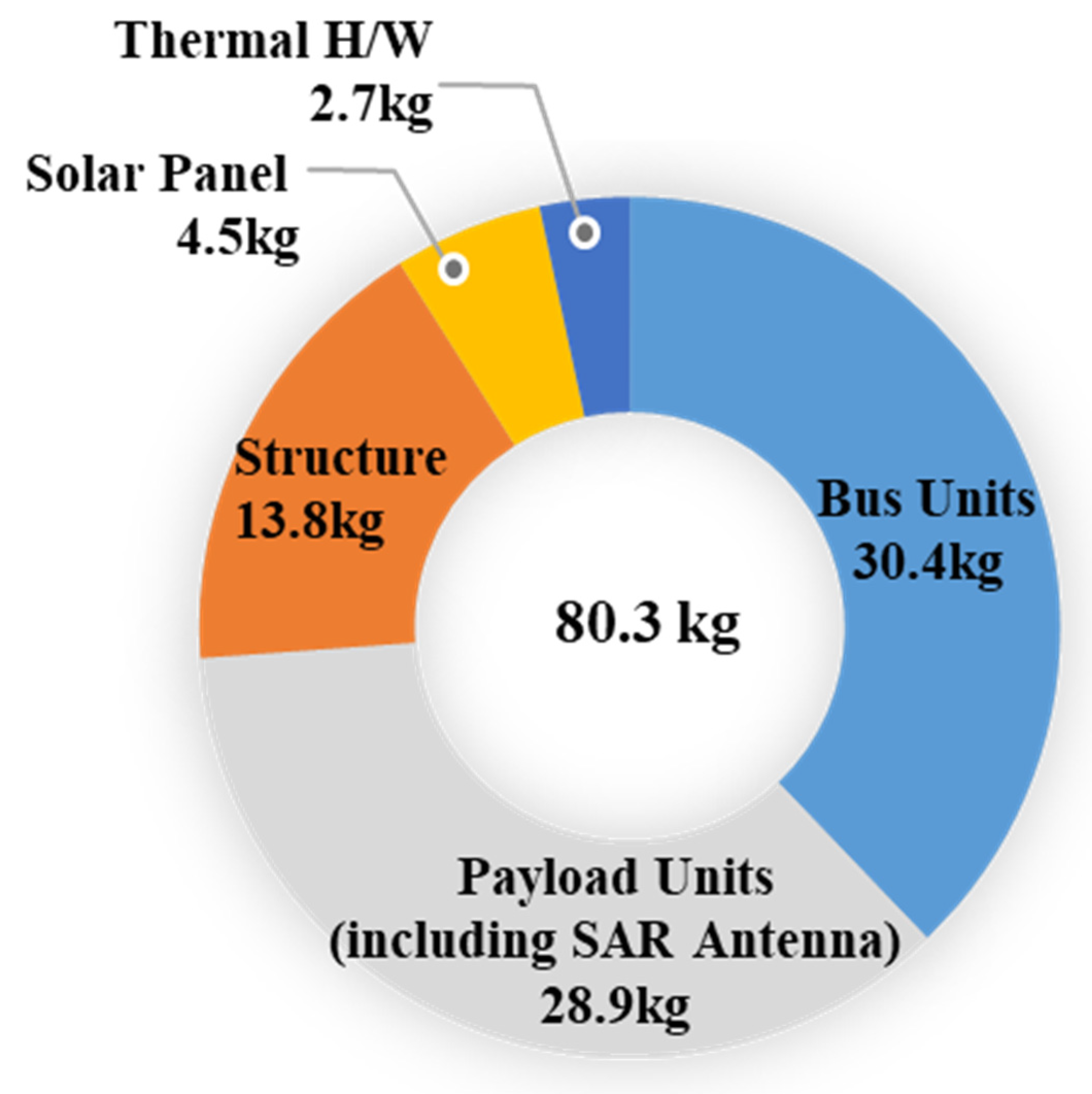
| Mass | 80.3 kg | |
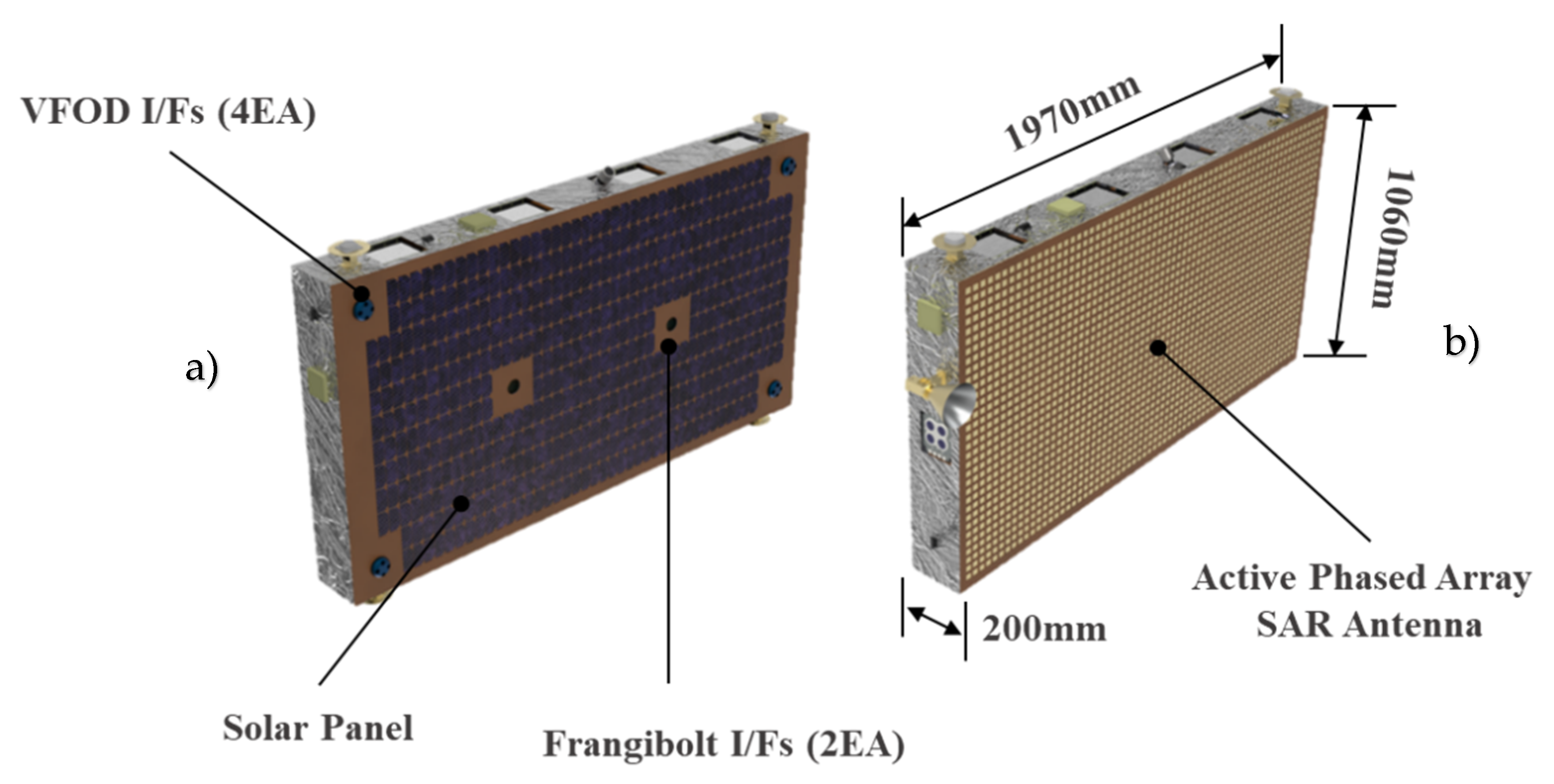
| Satellite Size | 1970 mm × 1060 mm × 200 mm | |
| Power | Generation | 340 W (BoL) |
| Save | 648 Wh | |
| Inter-Satellite Link | RF (S-band) | |
| TMTC/Image Downlink | S-band/X-band | |
| Pointing Accuracy | 0.085° (3σ) | |
| Resolution (≅25°) | 1 m (Stripmap), 4 m (ScanSAR) 1 m (VideoSAR) | |
| Swath (elevation × azimuth) | 5 km × 420 km (Stripmap), 15 km × 420 km (ScanSAR) 5 km × 5 km (VideoSAR) | |
| Image Acquisition Time (one pass) | 60 s (Stripmap), 10 s (VideoSAR) | |
| Frequency Band | Resolution | Swath Width | Acquisition Time | Peak Power | Mass |
|---|---|---|---|---|---|
| X-band | 1 m | 5 km | 60 s | 2560 W | 80 kg |
Publisher’s Note: MDPI stays neutral with regard to jurisdictional claims in published maps and institutional affiliations. |
© 2021 by the authors. Licensee MDPI, Basel, Switzerland. This article is an open access article distributed under the terms and conditions of the Creative Commons Attribution (CC BY) license (https://creativecommons.org/licenses/by/4.0/).
Share and Cite
Kwon, S.-C.; Son, J.-H.; Song, S.-C.; Park, J.-H.; Koo, K.-R.; Oh, H.-U. Innovative Mechanical Design Strategy for Actualizing 80 kg-Class X-Band Active SAR Small Satellite of S-STEP. Aerospace 2021, 8, 149. https://doi.org/10.3390/aerospace8060149
Kwon S-C, Son J-H, Song S-C, Park J-H, Koo K-R, Oh H-U. Innovative Mechanical Design Strategy for Actualizing 80 kg-Class X-Band Active SAR Small Satellite of S-STEP. Aerospace. 2021; 8(6):149. https://doi.org/10.3390/aerospace8060149
Chicago/Turabian StyleKwon, Seong-Cheol, Ji-Hae Son, Sung-Chan Song, Jin-Han Park, Kyung-Rae Koo, and Hyun-Ung Oh. 2021. "Innovative Mechanical Design Strategy for Actualizing 80 kg-Class X-Band Active SAR Small Satellite of S-STEP" Aerospace 8, no. 6: 149. https://doi.org/10.3390/aerospace8060149
APA StyleKwon, S.-C., Son, J.-H., Song, S.-C., Park, J.-H., Koo, K.-R., & Oh, H.-U. (2021). Innovative Mechanical Design Strategy for Actualizing 80 kg-Class X-Band Active SAR Small Satellite of S-STEP. Aerospace, 8(6), 149. https://doi.org/10.3390/aerospace8060149