1. Introduction
In the last few years, an increasing interest has arisen in the utilization of the LO
X/CH
4 propellant combination for space propulsion applications as testified by the efforts spent by several academic and research institutions, international agencies and private companies. The utilization of the LO
X/CH
4 combination for space propulsion applications provides many advantages, as indicated by several authors [
1,
2,
3]:
high specific impulse;
thrust-to-weight ratio performances;
good cooling capability;
engine reusability and throttlability;
fewer storage, handling and insulation concerns;
reduced pollution impact on ground, atmosphere and space;
compatibility with ISRU (in situ resource utilization) purposes for lunar/Martian missions.
These capabilities result in a large number of applications and missions enabled by methane-based propulsion systems, from in-space systems (landing or descent vehicles, service modules, etc.) to space launchers (main stages or upper stages). In fact, oxygen/methane couple represents a potential candidate to substitute hypergolic and solid propellants in the future. Thus, its versatility makes methane a good candidate for several applications, from in-space propulsion systems (service modules, landing or descent vehicles, and ascent stages) to accessing to space (first stages of launchers or upper stages) [
3]. Some important programs have recently been launched in Europe like the LYRA project (ASI/Italian Space Agency-Avio) [
4], which provided the first impulse to the development of future generation of VEGA upper stage engines, currently on-going due to AVIO efforts [
5]; Prometheus engine (100-t-thrust) project, led by CNES (Centre National d’Etudes Spatiales)/Airbus-Safran Launcher (France), is inserted in ESA FLPP Neo Program (European Space Agency Future Launchers Preparatory Programme) and is devoted to developing the future launcher family after Ariane 6 [
6]. In the Russian Federation, several projects, like Energomash, KBKhM (KB KhimMash/Volga staged combustion derived engine with up to 10 t of thrust), KBKhA (KB KhimAvtomatika) and Starsem (Soyuz), are historically active with this kind of issue and involved in several studies [
7]. Japan has reached high levels of readiness [
8] through the consolidated cooperation between JAXA (Japan Aerospace Exploration Agency) and IHI. In the United States, a lot of players are involved in several projects, oriented to different applications. It is worth remembering the SpaceX Raptor Project [
9], Blue-Origin (240-t-thrust BE-4 engine, based on staged combustion cycle) [
10] and NASA, developing a 20-kN pressure-fed engine, intended for the Morpheus lunar lander (Armadillo Aerospace, Mesquite, TX, USA) [
11].
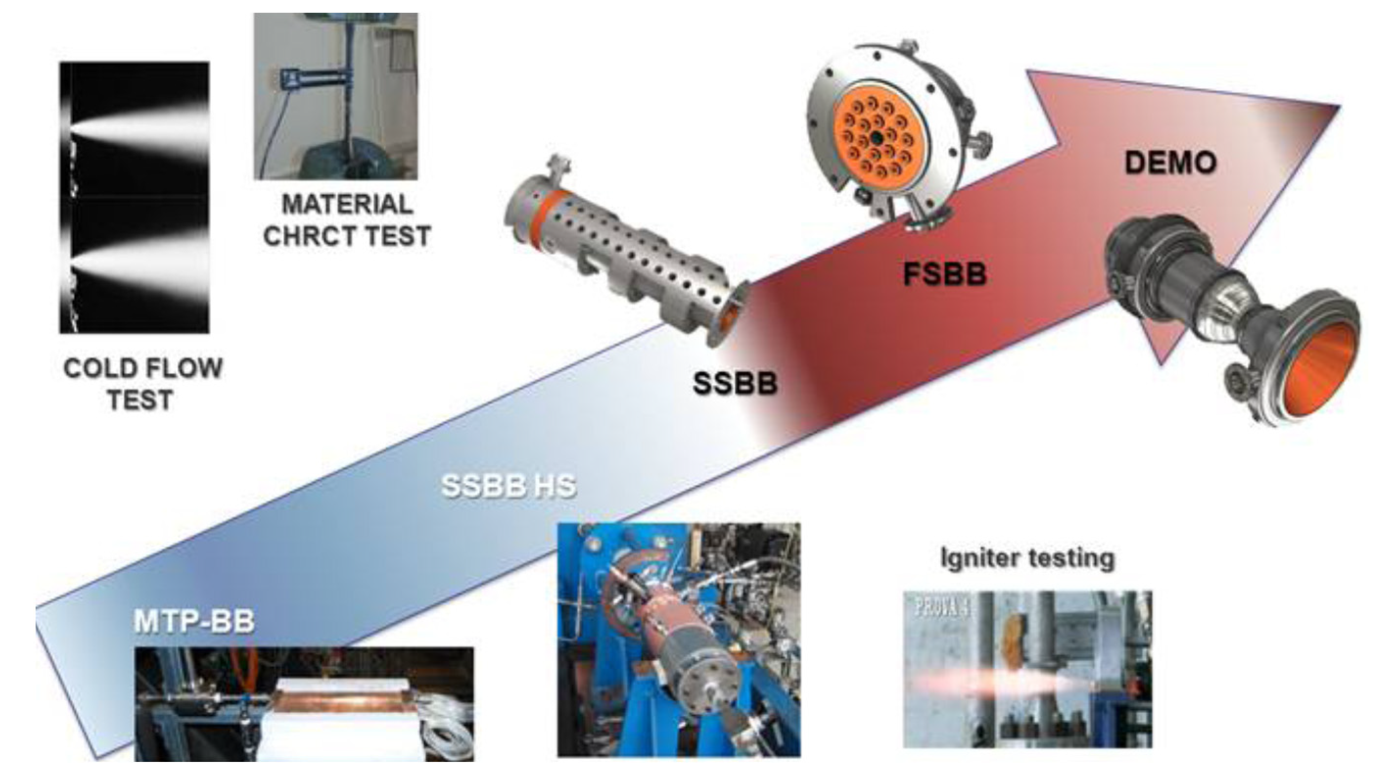
Besides the aforementioned initiatives, in Italy there is a strong interest in chemical space propulsion issues and in the liquid oxygen/liquid methane combination. In fact, the Italian Ministry of University and Research is funding a specific program devoted to the consolidation of current technologies, methodologies and manufacturing capabilities as well as the development of future propulsion systems. The program is named HYPROB (HYdrocarbon PROpulsion test Bench) and has been assigned to the Italian Aerospace Research Centre (CIRA) [
12]. Among the different goals, the most significant objective is the design, realization and testing of a LO
X/LCH
4 demonstrator (DEMO), capable of 30 kN of thrust. An incremental approach strategy has been adopted to enlarge the comprehension of critical physical aspects through the design, manufacturing and testing of specific test articles. Basic activities like the design and experiments on injectors or material characterizations have been accomplished. However, central issues were represented by the experimental campaigns on igniters and subscale mono-injector engines (to investigate the comprehension of supercritical combustion, heat release, injection and mixing phenomena, etc.) as well the experimental studies on methane transcritical behaviour as depicted by
Figure 1 [
13].
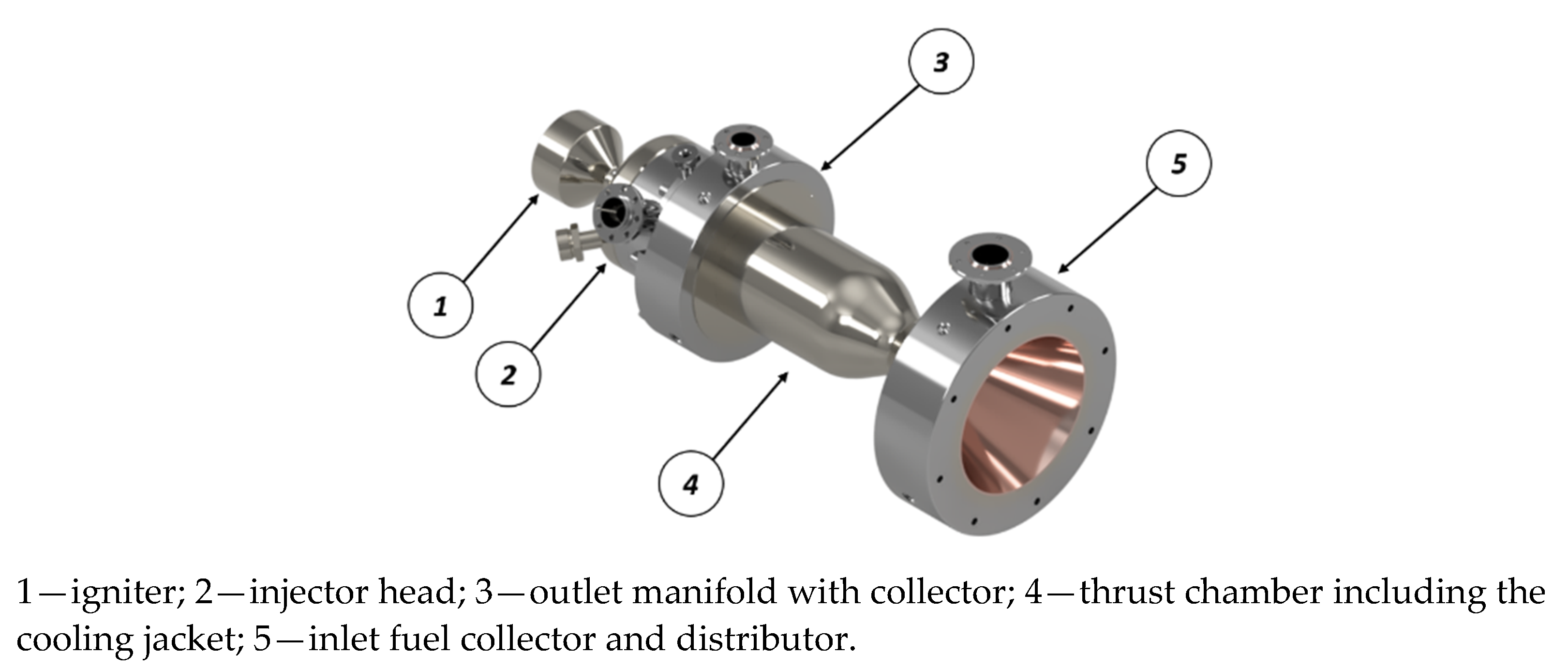
The final object is represented by a 30-kN-class-thrust demonstrator. The baseline thrust chamber assembly concept is depicted in
Figure 2: it includes an igniter, an injector head with 18 injectors and a regenerative cooling jacket with 96 axial channels and inlet/outlet manifolds. In
Table 1 the main parameters are detailed.
Based on a counter-flow architecture, methane enters the channels in the nozzle region in liquid phase, is heated by the combustion gases along the chamber and, then, injected into the combustion chamber as a supercritical gas through the injection head. The cooling jacket represents the most critical component: it is composed of an inner liner, made of high thermal conductive materials (generally copper alloys), and by a close-out structure, made up of robust alloys, like Inconel or nickel, and consists 96 axial channels, surrounding the combustion chamber. The design activities have been internally conducted by means of in-house codes, as reported by [
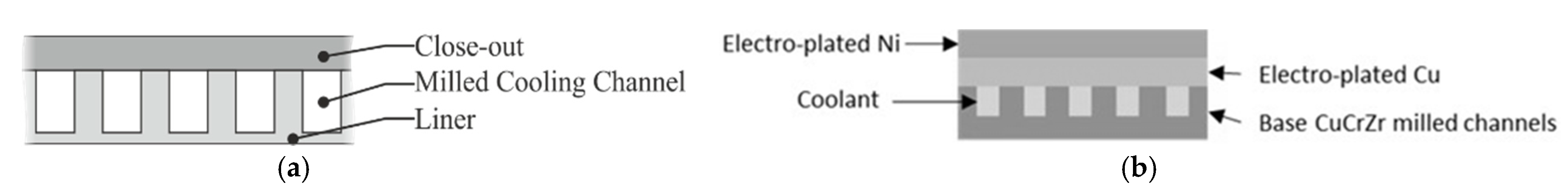
14], and supported by CFD analyses (to characterize the thermal and fluid-dynamic behaviour of the cooling jacket) and thermo-structural verifications. In the process of developing the final DEMO version, a firing test campaign is needed in water-cooled mode to characterize the cooling jacket behaviour and to accomplish qualification of the innovative manufacturing method (i.e., electroplating) selected to join the copper liner with the nickel close-out. In fact, CIRA, after accomplishing a specific technological activity, decided to substitute the planned use of a conventional process, based on brazing of non-homogeneous components, with galvanic deposition of copper and nickel layers for the realization of the cooling jacket. In fact, large difficulties were encountered in the repeatability of the brazing process for chambers with tens of cooling channels working in tough conditions: they have to withstand pressure values up to 16.0 MPa, are required to keep methane liquid as long as possible and huge thermal loads (fluxes up to tens of MW/m
2); walls should be as thin as possible for efficient thermal exchange and weight reduction purposes, as depicted in
Figure 3a. According to the new process, grooves in the liner part are milled and then overlaid with copper and nickel [
15]: in this way, channels are generated by a combination of two special galvanic depositions of pure copper and nickel, as depicted by
Figure 3b.
The advantages are summarized in: (a) brazing and welding free process since copper and alloys could be applied without thermal stresses and deterioration of base materials and (b) high reliability because the process repeatability can be controlled, improving mechanical resistance, thermal and electrical conductivity of the deposited copper. Thus, the use of this advanced process has been motivated by the possibility of avoiding any deterioration of base materials, and by a high level of repeatability and reliability [
16]. However, this choice led to a plan to optimize activity on the cooling system arrangement to adapt the brazed configuration to the electroplated one. At this point, the DEMO-0A manufacturing phase has been completed and the product has been accepted by means of leak and proof test (
Figure 4). The next step will be the integration with the injector head, already validated in a previous firing campaign, and the igniter in order to start the final test activity.
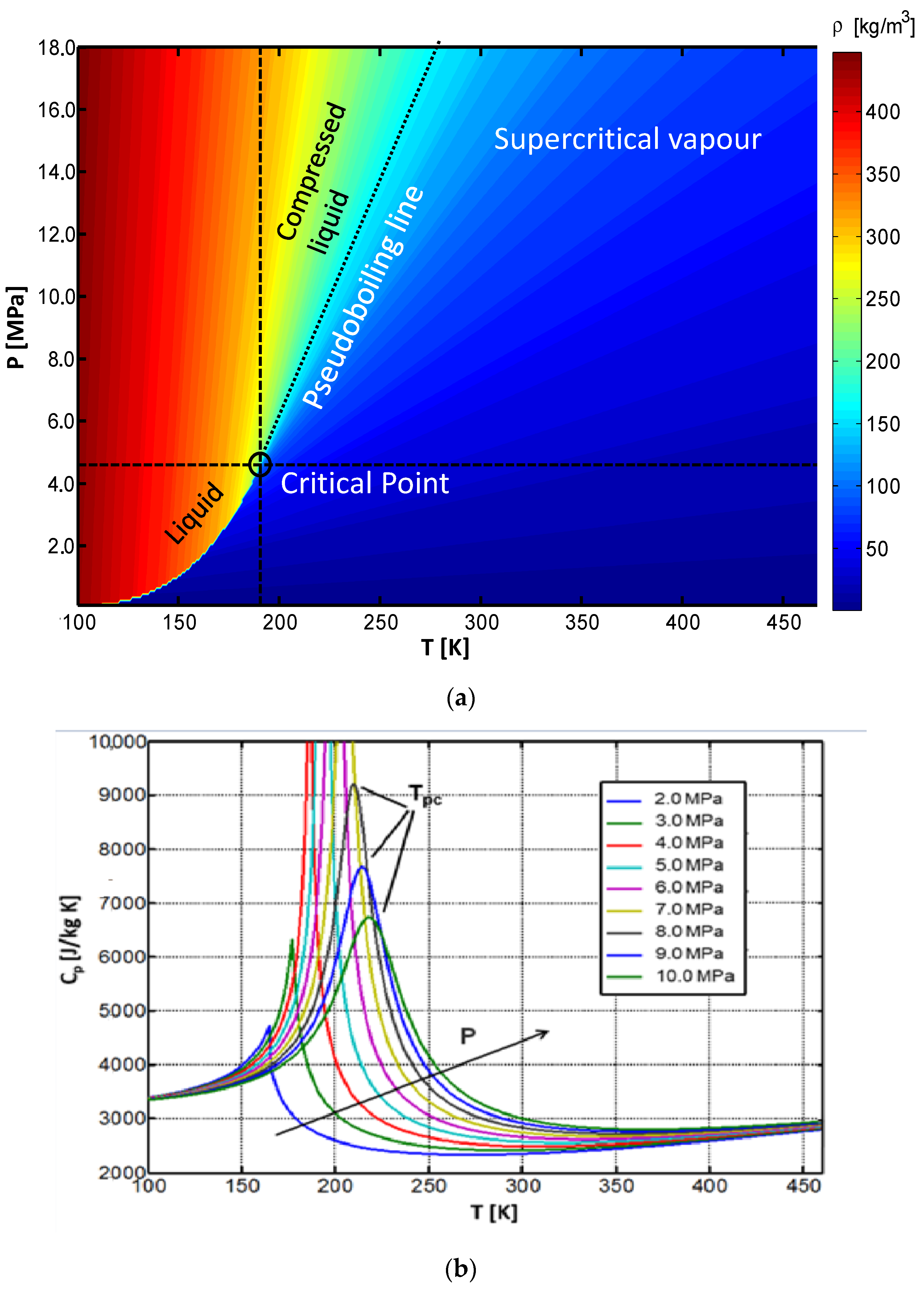
Concerning the description of the cooling jacket thermal behaviour, in a regeneratively cooled LRE, the coolant is represented by the propellant. Moreover, in the case of cryogenic fluids like methane or hydrogen, the propellant behaviour in terms of phase and working conditions evolves rapidly in the cooling jacket. Thus, fluid is injected into the cooling system in liquid state (characterized by values of pressure and temperature higher and lower than critical values, respectively) and generally undergoes a “pseudo-phase change” from liquid-like state to a vapour-like one, as carried out by [
18,
19]. Thermo-physical properties change quickly around the near critical zone (T
cr = 190.56 K and P
cr = 4.59 MPa for methane), as reported in
Figure 5a, but gradually if subcritical phase change phenomena are compared [
20,
21,
22]. As aforementioned, methane thermo-physical properties inside the LRE channels may change rapidly and a heat transfer deterioration phenomenon may be observed from to the axial coordinate where the specific heat at constant pressure exhibits the peak (pseudo-critical conditions, T
pc > T
cr) [
23,
24,
25]. Pseudo-critical temperature increases as pressure increases while the specific heat peak value reduces, up to vanishing at very high values of pressure, as depicted by
Figure 5b. Designers generally pay a lot of attention to properly conceiving the cooling passages to avoid the aforementioned critical phenomenon. In fact, due to the thermal stratification and disadvantageous physical conditions, low convective heat transfer coefficient values can be detected because a thin layer (behaving as a vapour and having low thermal conductivity) may divide the heated wall from the core, composed of liquid-like layers. In the view of developing robust design solutions for cooling jackets, risks, linked to the heat transfer deterioration on-set, can be reduced either by increasing the coolant pressure or by increasing the surface roughness [
24].
Given this background, the coolant flow analysis and the deep comprehension of fluid transcritical behaviour represent central points in the design activity of LO
X/LCH
4 rocket engines: the prediction of surface temperature and heat flux from the combustion gases to the engine wall is directly dependent on heat transfer capabilities of the coolant [
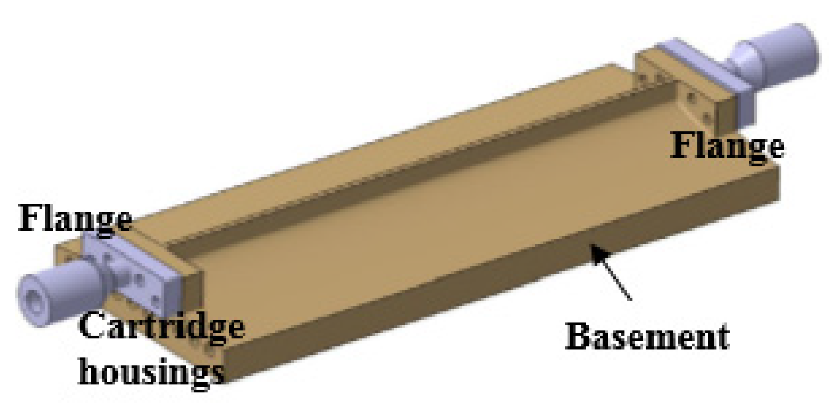
25]. Moreover, classical semi-empirical correlations for the evaluation of heat transfer coefficients do not work in the deteriorated mode and relatively high values of roughness, which may occur since the typical dimension of channels (in the order of some mm) also represent challenging conditions from a numerical point of view. Thus, an accurate investigation about configurations of rocket-engine-like cooling channels was needed before designing the DEMO jacket. For this reason, a specific test article, named MTP-BB (Methane Thermal Properties Breadboard) and shown by
Figure 6, has been designed by CIRA and tested at different conditions [
26]. The breadboard, made of a copper alloy, was provided with a single rectangular channel on the top, connected to the facility supplies through mechanical flanges, where temperature and pressure sensors were accommodated. Liquid methane was injected in the rectangular passage (mass flow rate ranging from 0.01 to 0.06 kg/s, T
in ranging from 120 to 140 K and P
in in the range 6.0–16.0 MPa) and gradually heated by means of the electrical cartridges, placed on the bottom part, to reach transcritical conditions before exiting. Several internal thermocouples were placed inside the body to collect temperature data at different axial positions and at a distance from the channel bottom up to 4 mm.
The collected experimental data were useful to conduct a rebuilding activity in order to set the thermal numerical models and support the design of the DEMO cooling jacket. In fact, the channel located on the top of the MTP breadboard has similar dimensions with respect to the DEMO cooling jacket; as well as, input heat flux (imposed from the basement), inlet conditions and mass flow rates are in the typical range of DEMO operating conditions. Details on the experimental rebuilding and validation activity are reported in [
26].
In this paper, both methane-cooled and water-cooled modes of the DEMO cooling system have been analysed through a 3-D CFD model regarding a single channel. The validation of the numerical procedure has been accomplished indirectly through the experimental results obtained in the MTP breadboard campaign for methane while waiting for future firing tests. However, the present investigation allows describing of the transcritical behaviour in an LRE typical cooling jacket, on one hand, and to compare the response of such systems, manufactured by means of different technological process, on the other one. In fact, comparisons between the brazed configuration of the demonstrator and the electroplated one, named DEMO-0A, are carried out to underline the achieved improvements under the thermal point of view. CFD results were adopted as input for the thermo-structural simulations, needed to evaluate the lifecycle of the thrust chamber assembly.
2. Materials and Methods
The final demonstrator architecture provides a regeneratively cooled ground engine, which implements a typical counter-flow architecture. The cooling jacket is characterized by several narrow axial channels, defined in the bottom part by a copper alloy liner, covered with electrodeposited layers of pure copper and pure nickel, or by a brazed nickel part, which represent the close-out part.
An in-house design tool, based on typical correlations, was developed to design the cooling jacket in terms of channel dimension, liner and rib thickness [
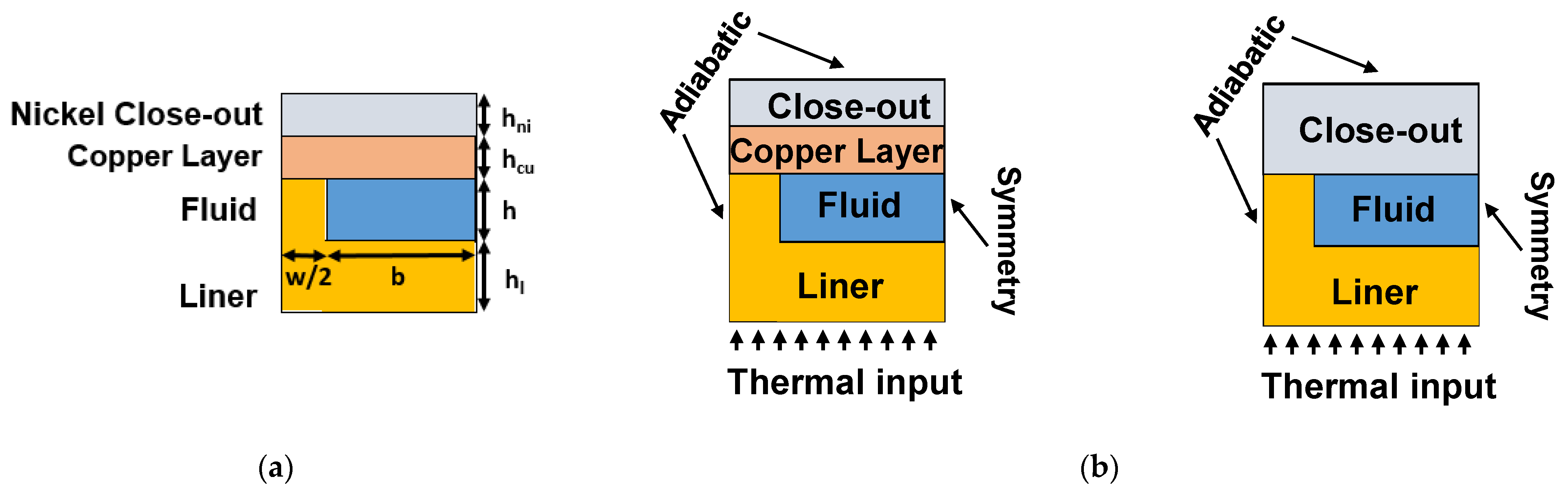
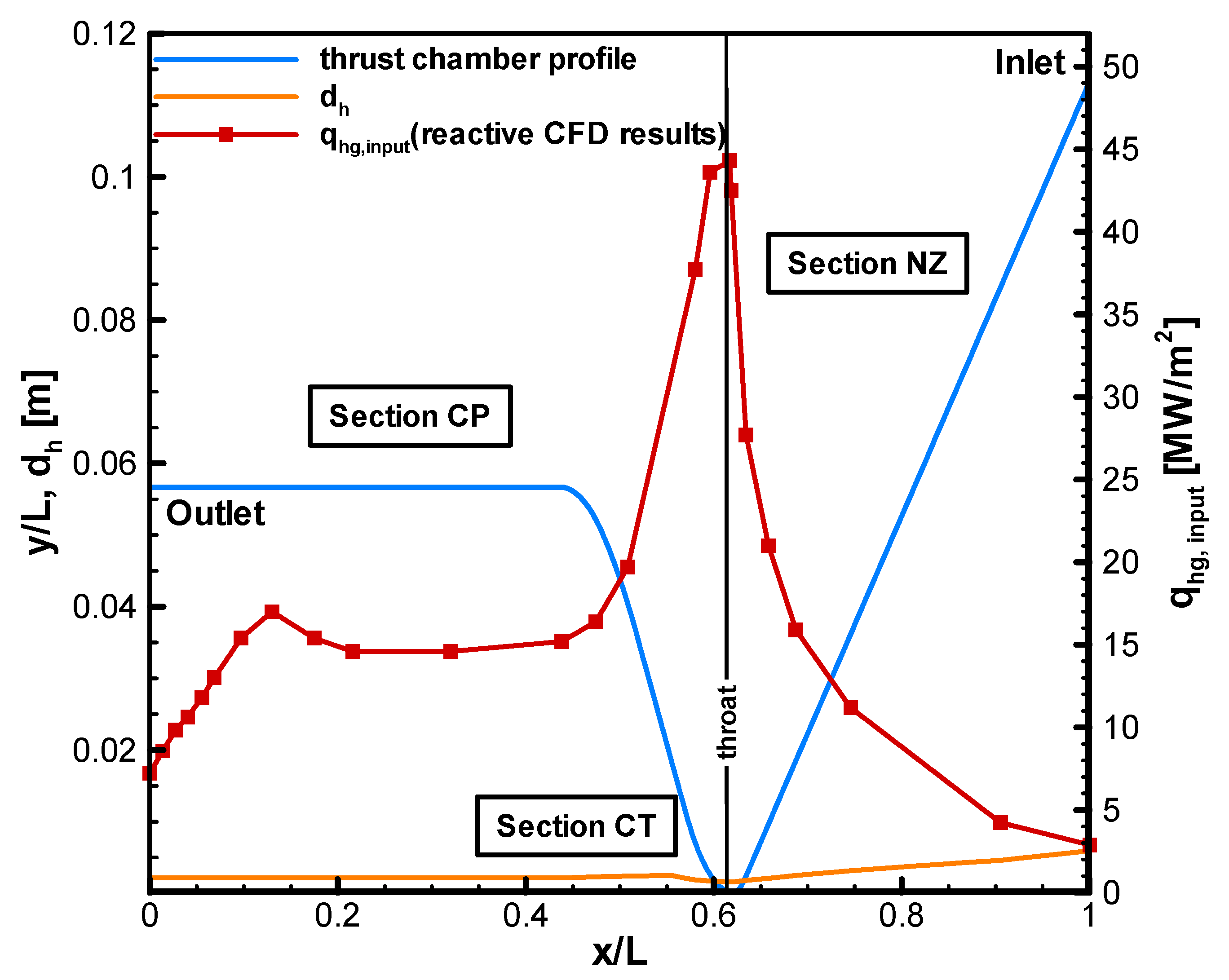
14]. The adopted strategy considers a constant number of channels and a constant value for the rib width (w) while a variable value of the rib height (h) has been considered, according to
Figure 7a. In this way, an optimization of the cooling performances was achieved, taking into account some significant sections, such as the nozzle (NZ), throat (CT) and cylindrical part (CP), highlighted in
Figure 8. Furthermore,
Figure 8 depicts the dimensionless profile of the thrust chamber, the variations of cooling channel hydraulic diameter (d
h) along the axial axis and the applied heat flux profile (defined as “nominal” in the “Results and Discussion” section), representing the design profile. It has been calculated through reactive simulations inside the combustion chamber [
15].
Considering L, the overall thrust chamber length, as the reference length, the geometric parameters are equal to:
channel height (h/L), ranging from 0.0018 to 0.0061;
channel width (b/L), ranging from 0.0019 to 0.0107;
rib width (w/L) = 0.0032;
liner thickness (h1/L) = 0.0020;
copper layer height (hcu/L) = 0.0023;
nickel layer height (hni/L) = 0.0034.
In the case of the DEMO brazed version, the copper layer and nickel close-out are substituted by a unique Inconel part, joined with the liner rib through the brazing process.
The numerical investigations on a single DEMO cooling channel, extracted from the complete model, were performed by means of ANSYS Fluent v17 (Canonsburg, Pennsylvania, USA) [
27]. The solution of the governing equations, such as continuity, momentum and energy in three-dimensional form were accomplished in a steady state regime and considering an NIST (National Institute of Standard and Technology) real gas model and turbulent flow with thermo-physical properties, calculated through REFPROP v7.0 database [
28]. Conduction effects have been contemplated. Rough channel walls have been taken into account while
k-ω sst turbulence model was assumed [
27,
29]. A pressure-based method was selected to solve the energy and momentum equations and a second-order upwind scheme was chosen together with PISO (Pressure-Implicit with Splitting of Operators) coupling to couple pressure and velocity, respectively. Concerning the convergence criteria, residuals of velocity components and energy values were considered equal to 10
−6 and 10
−9, respectively. Initialization was performed at inlet section conditions, P
in = 16.0 MPa and T
in = 110 K for methane-cooled mode (overall mass flow rate is equal to 1.92 kg/s). For the water-cooled mode (overall mass flow rate is equal to 4.5 kg/s and 5.0 kg/s) P
in = 16.0 and 12.0 MPa (to take into account different test conditions offered by the test facility) and T
in = 293 K, respectively, were adopted. A NIST real gas model was applied and the single-species flow form was selected to eventually handle both liquid and vapour phases in supercritical pressure conditions [
27,
28], in the case of methane. In fact, if methane is considered, it is fundamental to the transcritical operating conditions of the working fluid since both the simulation initialization and the convergence history can be influenced.
According to
Figure 7a,b, the considered solid materials were: (a) a copper alloy (CuCrZr) for the liner, chosen because of its high thermal conductivity and good mechanical properties, for both modes; and (b) Inconel or pure nickel, due their mechanical performances, for the close-out part in the case of brazed and electroplated versions, respectively. For DEMO-0A, a copper layer was deposited between the liner and the external close-out. The thermo-physical properties of all the materials were assumed to be dependent on temperature and they were calculated through a characterization campaign [
14].
Simulations contemplate a half channel to limit the computational efforts; in fact, a symmetry condition is adopted (due to the geometrical, thermal and fluid-dynamic symmetry); top wall was considered adiabatic (for a conservative approach) as well as the left one to take into account half rib. The thermal load was applied on the liner bottom surface by means of specific user-defined functions (udf). Moreover, the following boundary conditions have been assigned:
inlet section: uniform velocity (at a fixed mass flow) and uniform temperature profile;
outlet section: pressure outlet in order to define the static pressure at flow outlets;
channel walls: velocity components equal to zero.
The nominal heat flux profile, adopted for the design, is depicted in
Figure 8 and was obtained through reactive CFD simulations of the combustion chamber side, considering the thrust walls at a temperature of 300 K [
15]. However, this approach is conservative but useful to adopt suitable margins in the cooling jacket design; then, a weak thermal coupling was taken into account for further analyses, as suggested by [
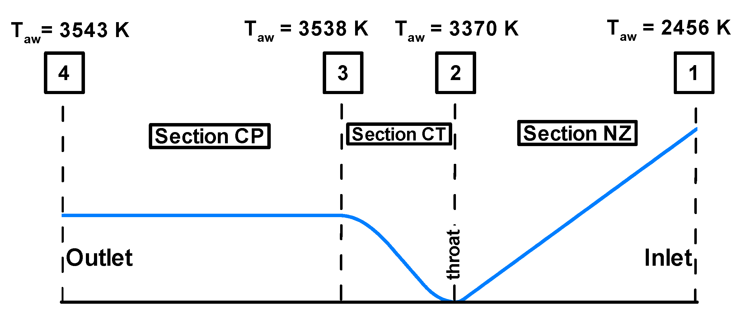
18]. In this case, the thermal load was applied by means of a hot gas side convective heat transfer coefficient, calculated by scaling the “design” heat flux (obtained at a constant value of T
wg equal to 300 K) and considering the average hot gas temperature inside the chamber (T
aw), according to Equation (1). T
aw values, given in
Figure 9, are evaluated through RPA code [
30] for four significant sections, corresponding to inlet (1), throat (2), convergent/cylindrical part interface (3) and outlet (4). Then, at a fixed position, T
aw is calculated by means of a linear interpolation between the values of adjacent sections.
With regards to the adopted mesh, a structured grid, composed of about 2.7 million nodes, was chosen and a sketch is reported in
Figure 10. A mesh sensitivity analysis, described by
Table 2, was conducted on the model considering the nominal conditions (nominal input heat flux, T
in = 110 K, P
in = 16.0 MPa and
m = 0.01 kg/s for single half channel). Three structured mesh distributions (“coarse”, “fine” and “finest”), generated by following the mesh suggestions given by Ansys Fluent user’s guide in the case of rough channel walls [
27], were considered: they have about 1.3, 2.7 and 5.6 million nodes, respectively. Finally, the second grid case was chosen to perform the investigations, presented in the present paper, because it ensured a good compromise between the machine computational time and the accuracy requirements.
The numerical approach and settings were validated through results obtained in the rebuilding activity of the test campaign conducted on the aforementioned MTP breadboard, described in
Figure 6, with regard to the transcritical behaviour of methane [
15,
26]. In fact, the test article was provided with a channel, having dimensions representative of ones adopted in the DEMO and this is also true for the operating conditions.
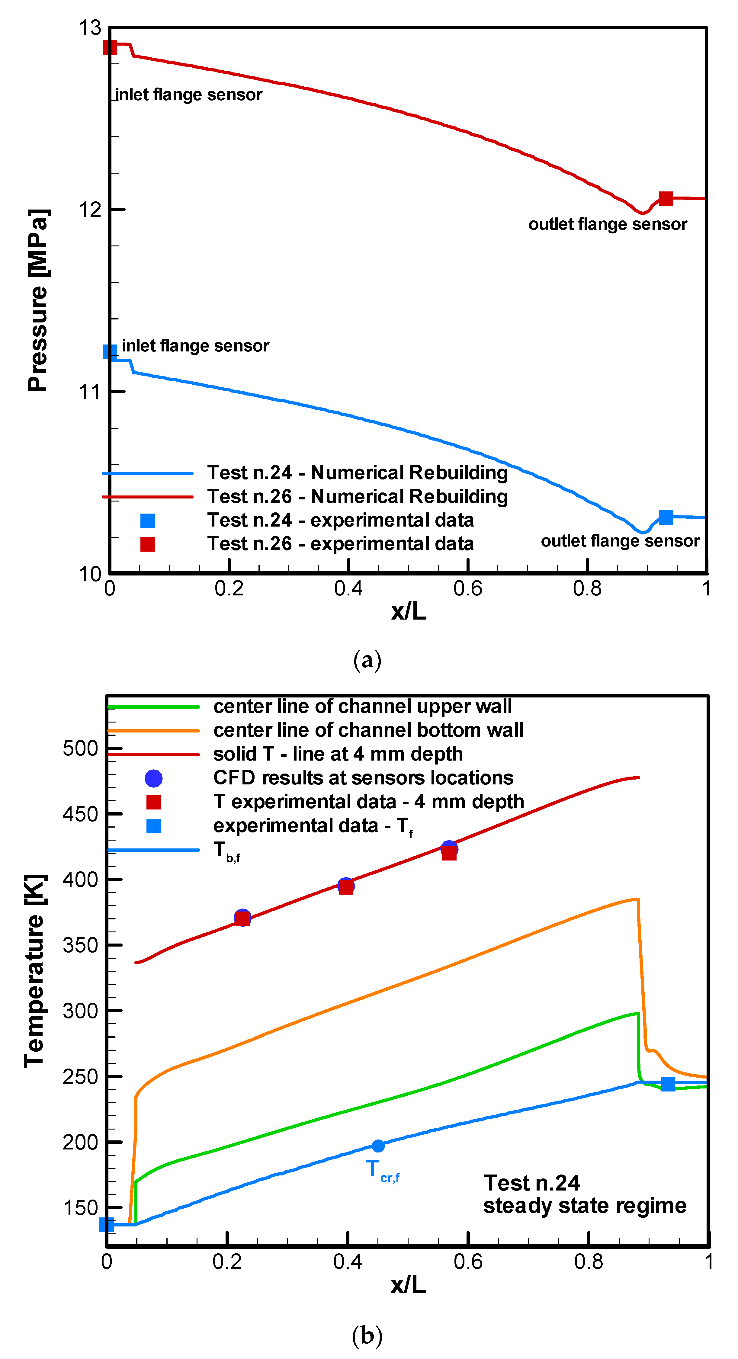
Figure 11 reports the comparisons between the experimental data (when stationary thermal regime was reached) and the numerical results for two relevant test cases: test #24 and test #26, characterized by mass flow rates equal to 20.87 g/s and 20.57 g/s, T
in = 137.1 K and 140.8 K, and P
in = 11.21 MPa and 12.89 MPa, respectively. Numerical results fitted the experimental data very well, as depicted by
Figure 11a,b with regards to pressure and fluid bulk temperature axial profiles, which are compared with test data. Moreover, very low discrepancies are observed in terms of solid temperature results if the numerical temperature profile at a distance of 4 mm from the channel base is compared with the related experimental data for test #24, as reported in
Figure 11b. Further details on CFD simulations, modelling, solving strategies and both numerical and experimental results are given in [
26].
3. Results and Discussion
In the present paper, results for numerical simulations ran at nominal conditions (Tin, f = 110 K, Pin = 16.0 MPa and overall m = 1.92 kg/s) for methane mode for both the DEMO configurations, characterized by the electrodeposition and brazing process, are presented. Moreover, since the validation of the electrodeposition process will be accomplished by means of a specific test campaign considering water as refrigerant evolving in the demonstrator cooling system, the following initial conditions are also taken into account: Tin, f = 293 K, Pin = 16.0 and 12.0 MPa and overall m = 5.0 and 4.5 kg/s. These conditions were set according to the capabilities expressed by the test bench.
The test matrix is reported by
Table 3.
Results are presented in terms of axial profiles for the liner and channel wall temperature, fluid bulk temperature, convective heat transfer coefficient and pressure drops as well as fluid significant properties. Moreover, some temperature and fluid properties’ field plots, including some slices of significant interest, are presented.
Figure 12 and
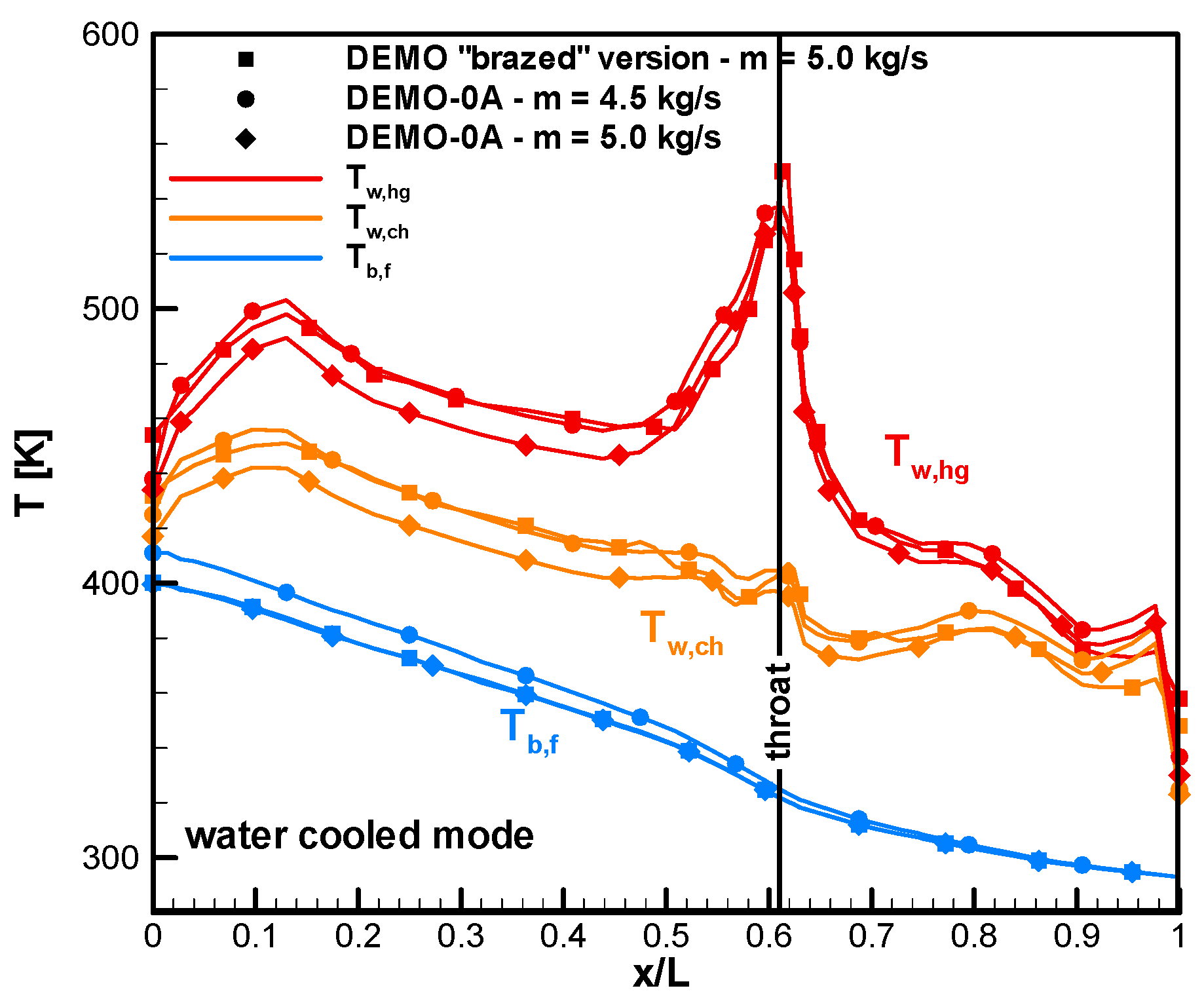
Figure 13 depict the axial profiles of hot gas walls, channel bottom walls and fluid bulk temperature for water-cooled and methane-cooled modes, respectively. Both figures point out that DEMO-0A, the optimized electroplated configuration of DEMO, presents a general reduction in terms of thermal stresses with respect to the brazed version. This is mainly due to the insertion of the copper layer to overlay the liner part and the possibility of changing the close-out material from Inconel to pure nickel. For the water-cooled mode, temperature peaks in the throat region and in the cylindrical section of the chamber resulted in reductions of about 30–40 K for a fixed mass flow rate (i.e., 5.0 kg/s), as depicted by
Figure 12. A little decrease in terms of mass flow rate (4.5 kg/s, i.e., −10%) causes DEMO-0A profiles to overlap with ones obtained for the brazed version at mass flow rate equal to 5.0 kg/s. Moreover, fluid bulk temperature increases from about 400 to 420 K as mass flow rate decreases; water constantly remains in liquid phase, because of high pressure conditions as confirmed by the fluid bulk profiles and maximum values of channel walls.
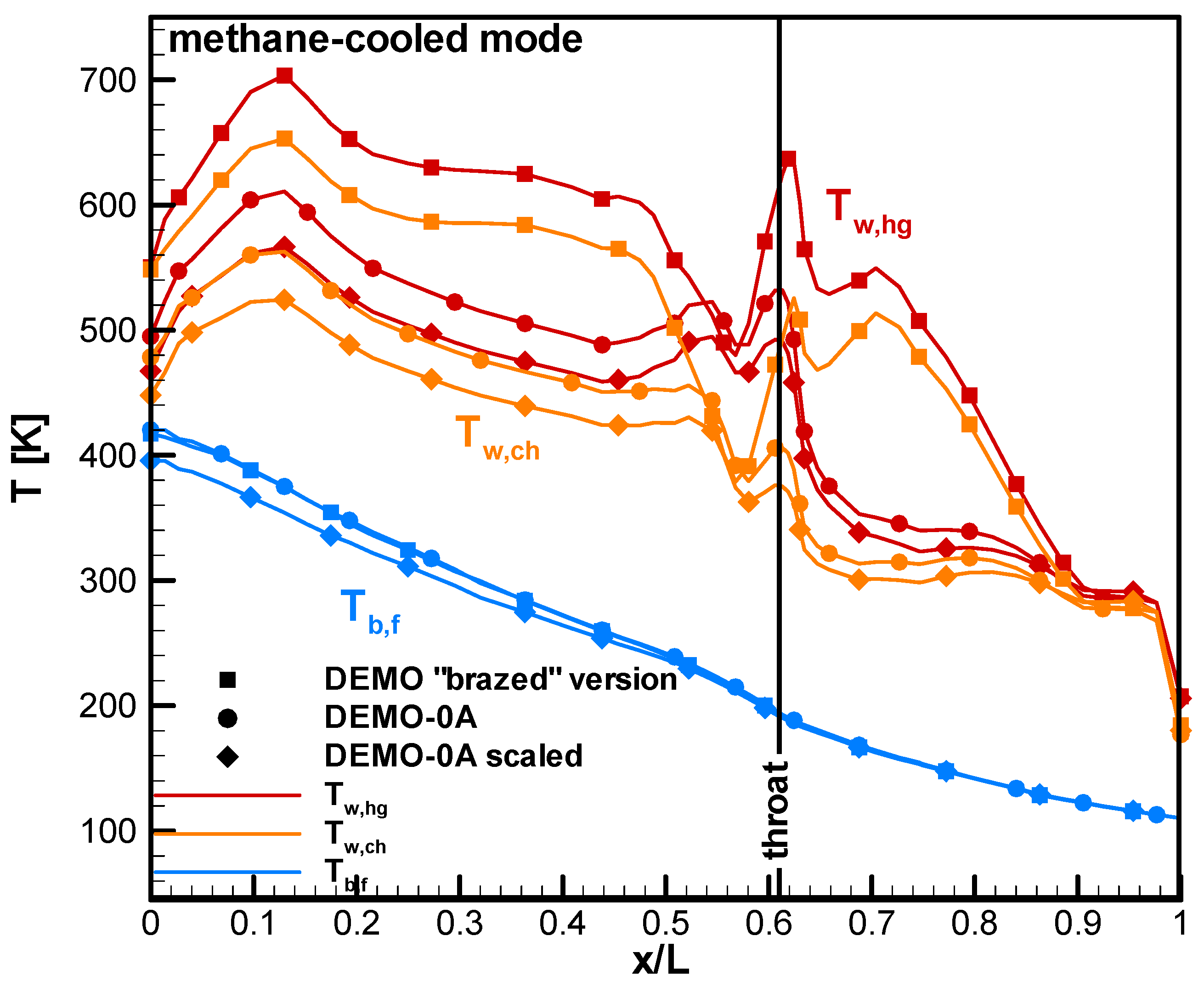
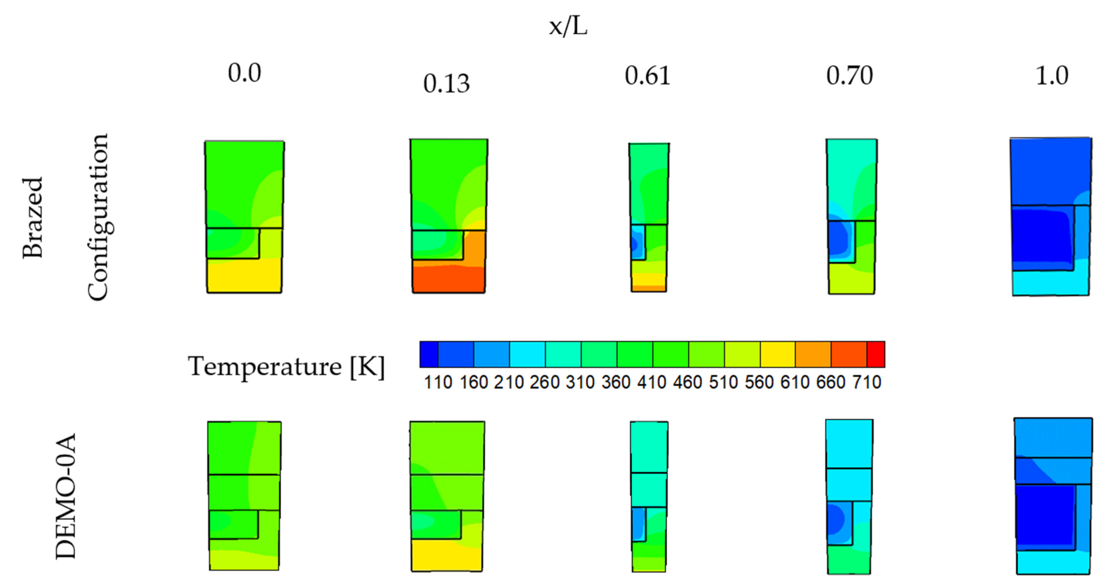
If methane is considered as refrigerant, the thermal behaviour of the DEMO-0A and the “brazed” versions of the DEMO detach significantly from each other, as depicted by
Figure 13. Temperature peak in the throat section (x/L = 0.61), where the highest heat flux is imposed, reduces from about 640 to 540 K while the absolute maximum, observed at about x/L = 0.13 (in correspondence with the re-attachment zone of hot gases on the combustion chamber wall) decreases by about 90 K in DEMO-0A. Moreover, it is worthy to emphasise that in that zone, methane flows as a supercritical gas. A third relative maximum, observed in the brazed configuration and located in the divergent zone, tends to disappear in DEMO-0A, due to a reduced local thermal stratification of the fluid. In fact, all the channel walls are made of copper alloys or pure copper, including the upper wall, and this determines a more homogeneous heat distribution inside the material and, consequently, in the fluid. Moreover, from that region fluid begins to locally change its conditions from a “liquid-like” to a “vapour-like” one, as depicted by the fluid bulk temperature profile: the working fluid, after entering in liquid conditions, reaches critical temperature (about 190 K) near the throat region. From this section, methane tends to behave like a highly compressible fluid near the hot walls of the channel, and like a liquid near the cold ones, especially in the upper part of the channel. However, moving towards the outlet section, a larger fluid fraction behaves like a vapour. In the cylindrical part, methane is completely composed of a supercritical gas since the temperature is very high and the pressure is much higher than the critical value (4.6 MPa). If the “scaled” thermal load (considering a weak coupling approach) is applied, the liner results in being less thermally stressed as expected and, in fact, a reduction of about 40 K is evaluated in terms of temperature peaks, located at x/L = 0.61 and x/L = 0.13.
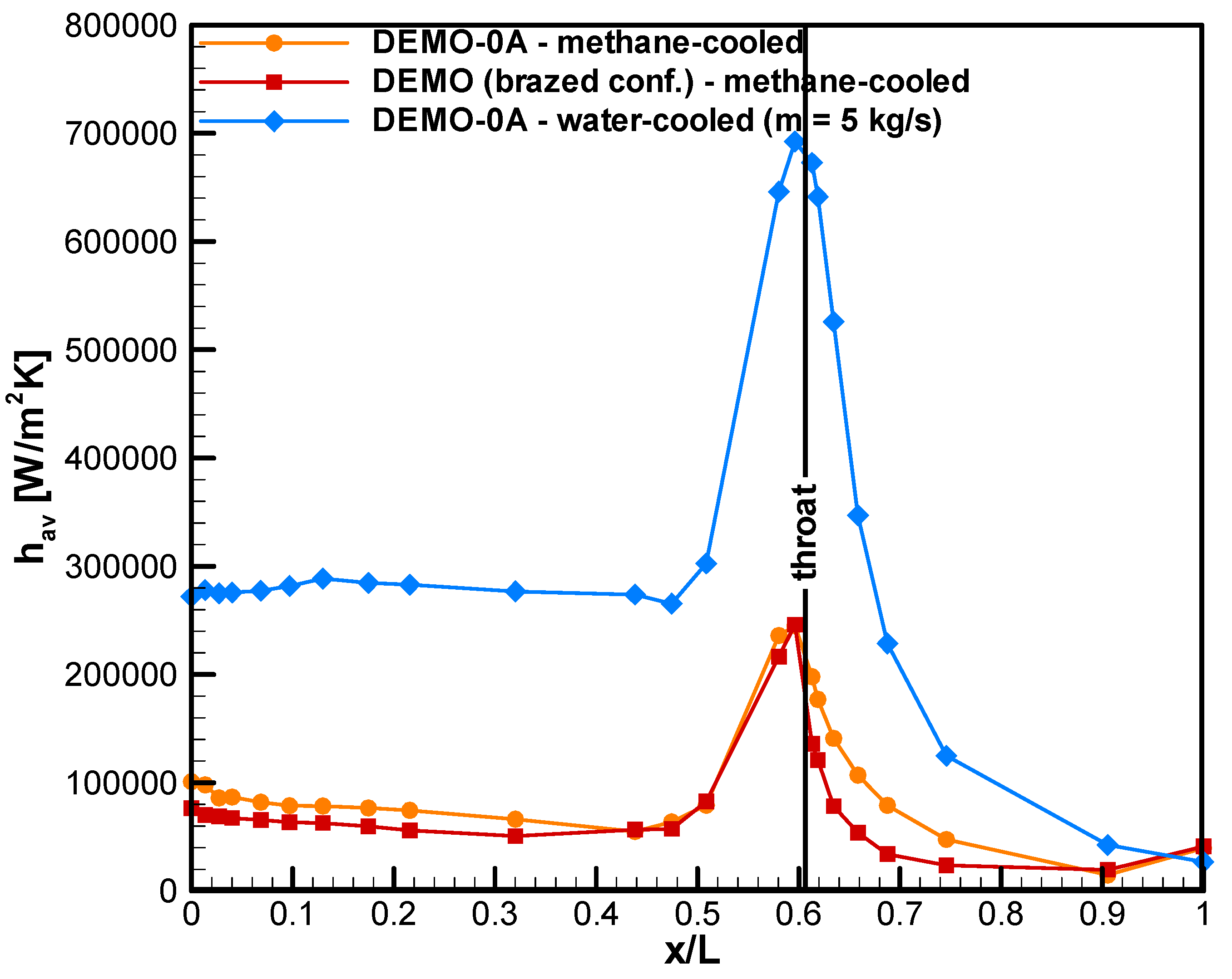
Figure 14 depicts the axial profiles for average convective heat transfer both for DEMO-0A and DEMO in the brazed configuration. It is shown that values are generally higher in the case of DEMO-0A if methane is considered as refrigerant and it is particularly evident in the divergent part and in the cylindrical part of the cooling system. Although, in the divergent zone, the fluid is in large part in liquid form, especially near the inlet section where the heat transfer coefficient values are lower than the ones obtained in the cylindrical part, where methane behaves like a supercritical vapour. This is mainly due to the high velocity attained by the fluid in the last sections of the cooling jacket, while in most of the divergent part velocity remains low because of fluid state and the channel cross section dimension. Maximum values are attained in the throat region, where the minimum dimensions of passages are designed, and there are very little differences between the versions. Moreover, a profile for the water-cooled DEMO-0A mode is plotted in order to compare data, underlining that the convective heat transfer values are larger in the case of water because of its basic thermo-physical properties.
Regarding static pressure profiles, plotted for the DEMO-0A version in
Figure 15, it is clear that pressure drops in the nozzle are very low because methane behaves like a liquid. The highest increase is localized in the convergent part and the cylindrical one, as pointed out in
Figure 15, because density is very low and velocity tends to increase towards the outlet section. As a result, large pressure drops are evaluated although methane mass flow rate is about 2.5 times lower than water in the water-cooled mode. In fact, in the water-cooled mode, the refrigerant remains in liquid form throughout the system.
Figure 16 depicts the temperature field for DEMO-0A, including channel walls and some slices, pointing out that maximum temperature values are attained in correspondence with throat region and re-attachment point while
Figure 17 gives a comparison with DEMO brazed configuration considering some significant cross sections. It is evident that the liner part is hotter if the brazed version of DEMO is compared with DEMO-0A in all of the considered cross sections. Furthermore, for both versions, it is shown that the thermal stratification of fluid is significant: near the bottom of the channel and near the rib walls the refrigerant is very hot while moving up towards the upper part of the channel, the temperature tends to decrease as it is possible to observe the sections until the throat region). Moreover, after entering the jacket as a compressed liquid, the fluid is heated by the hot gases and from the throat region exhibits temperature values higher than the critical one on average. In this region and in the first part of convergence, it is possible to observe a gas-like fluid moving near the bottom walls of the channels while a liquid-like one is present in the upper parts.
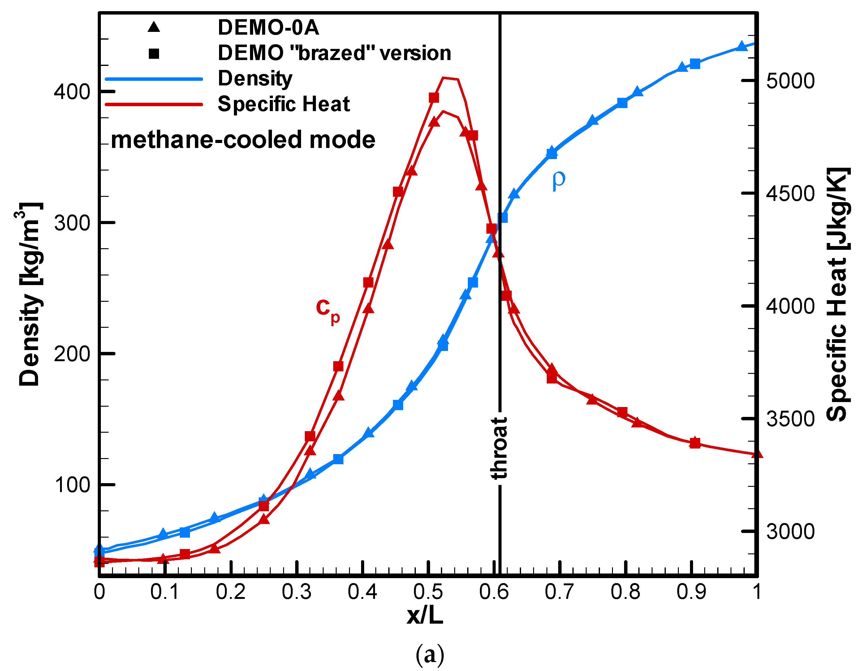
After the convergence zone, the fluid appears to be in supercritical gas state. This is also confirmed by the density axial profiles, strictly linked to temperature ones, and by the specific heat distribution, given in
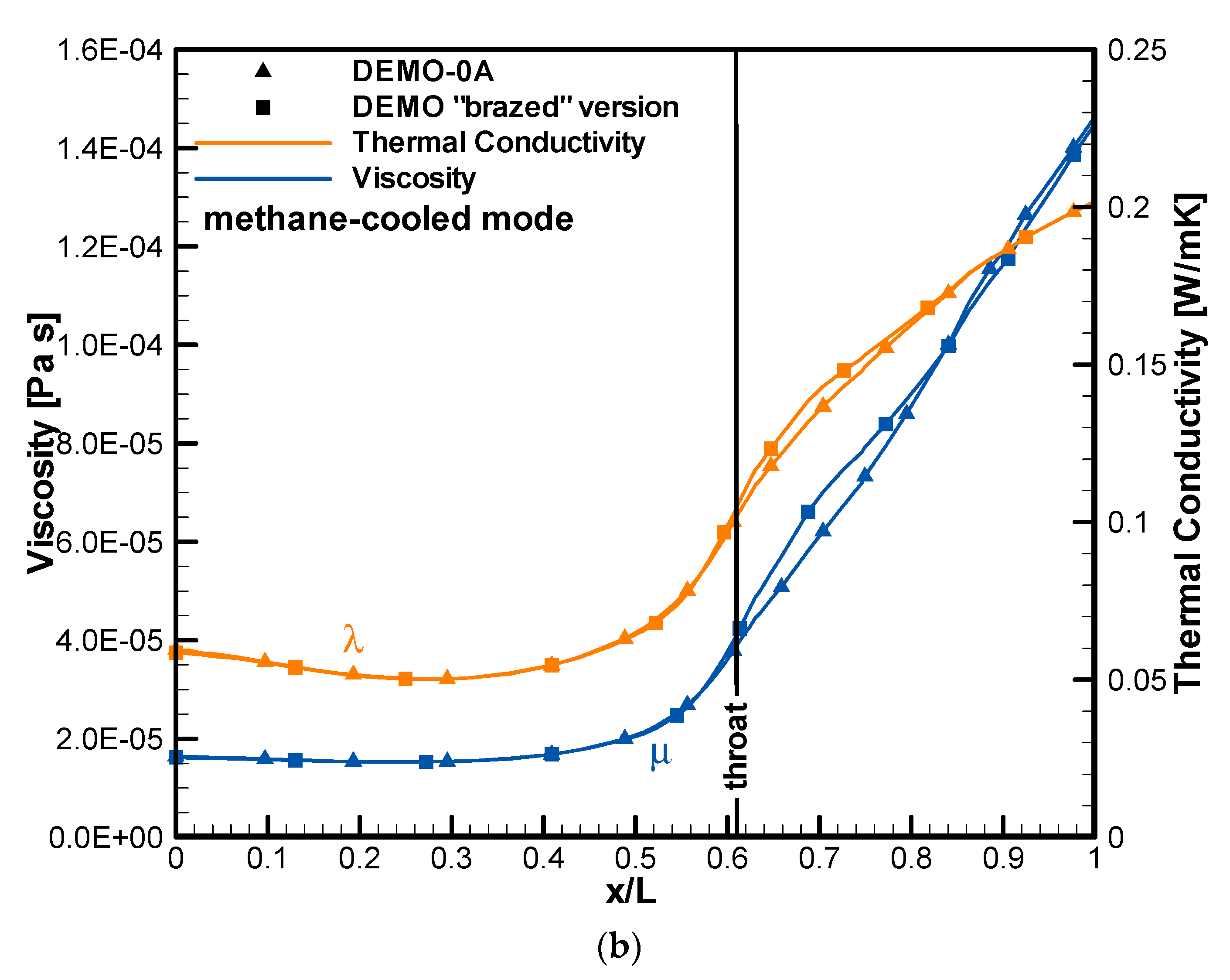
Figure 18a: from the throat region, the fluid core is characterized by low values of density and high values of specific heat. In particular, this is evident in the convergence section where a large part of the fluid exhibits the highest values of specific heat while relatively low values of thermal conductivity can be detected. The pseudo-critical condition is observed at about x/L = 0.50 and in that region low thermal conductivity values are observed as depicted by
Figure 18b. However, a deterioration mode, characterized by a sort of a thermal barrier between the fluid near to the hot wall and the cold upper part of the channel [
22], is not significant for both the demonstrator versions. In fact, aforementioned profiles of the liner temperature do not exhibit this phenomenon and this is due to the channel dimensions (optimized by means of the design codes), relatively high value of the wall roughness and fluid pressure, sufficiently far from the critical value [
23].
4. Conclusions
In this paper, the thermal and fluid-dynamic analyses, supporting the design of the cooling system of the 30-kN thrust class HYPROB LOX/LCH4 demonstrator, were discussed. In particular, the final demonstrator cooling jacket configuration, based on electroplating manufacturing process was analysed by means of 3-D CFD simulations and compared with the behaviour of the original brazed configuration. An NIST real gas model was adopted to describe the behaviour of evolving fluids and, in particular, of the transcritical conditions experimented by methane flowing in the cooling system. The selected arrangement was discussed by means of results, given in terms of temperature, fluid bulk temperature and pressure profiles. Simulations supported the optimization of the design of the cooling jacket, realized through electrodeposition: in fact, the most thermally stressed zones, such as the throat region and the re-attachment point zone, were identified.
The adoption of the electrodeposition process, instead of the brazing one, led to significant thermal benefits all over the cooling jacket. In fact, in the case of nominal operating conditions and if methane cooled versions are considered, a decrease of about 100 K is observed both in the throat region (x/L = 0.61) and at the end of the cylindrical part of the chamber (x/L = 0.13), as shown by
Figure 13. In fact, convective heat transfer values are generally higher in the case of DEMO-0A and the differences with the brazed configuration are significant in the divergent part (t times higher at maximum) and in the cylindrical part of the cooling system (1.2 times on average), as can be observed in
Figure 14. Moreover, a different behaviour is observed in the divergent zone, where a thermal relaxation of the liner is reported, since at x/L = 0.70, a difference of about 180 K is evaluated comparing DEMO-0A results with the brazed configuration ones. This is due to the reduced thermal stratification of fluid in the case of the electroplated demonstrator, as also evident from the temperature field given for the cross-section at x/L = 0.70 in
Figure 17. In addition, the water-cooled mode was considered since the first firing campaign will be conducted considering water as refrigerant to accomplish the acceptance tests of DEMO-0A and to validate the adopted technological process. In the water-cooled mode, temperature peaks in the throat region and in the cylindrical section of the chamber decreases by about 30–40 K for a fixed mass flow rate in the electroplated version of demonstrator, as reported in
Figure 12.
Results about the most significant thermo-physical properties have been presented to describe the transcritical behaviour of methane inside the cooling jacket. Furthermore, temperature fields in
Figure 17 have been discussed to underline the thermal stratification occurring inside the channel and the thermal response of the liner. Methane, injected as a compressed liquid, tends to be in those conditions until half divergent, then the fluid layers near the bottom part of the channel tends to behave like a vapour. In the throat region the fluid bulk temperature reaches critical values (about 190 K on average) and all the thermo-physical properties dramatically change in the near-critical conditions as depicted by
Figure 18 while the pseudo-critical conditions are attained in the convergent part (at x/L = 0.50). No peaks or temperature irregularities are observed in that zone; thus, no evident thermal deterioration phenomena are significant since pressure is two times the critical values. In the cylindrical part of the chamber, the fluid is fully composed of a supercritical vapour.
The present activity was propaedeutic to perform thermo-structural simulations, necessary to estimate the lifecycle of the thrust chamber assembly, whose manufacturing has been recently completed and is ready to withstand the firing test campaign. The adoption of the electroplating process, instead of the brazing one, to join the liner and the close-out has provided evident benefits in terms of the thermal response of the demonstrator (besides the other advantages linked to the process repeatability and the absence of heat treatments). It is expected that the objective of 5 firing tests with a duration of 30 s (considering a safety margin of 4) will be fulfilled. After completing the test activity, experimental results will be extracted to run further simulations and accomplish a wide numerical rebuilding activity.


