Article

Numerical and Experimental Investigation of Oil-Guiding Splash Lubrication in Light Helicopter’s Reducers

1
College of Mechanical and Electrical Engineering, Central South University, Changsha 410083, China
2
Hunan Aviation Powerplant Research Institute, AECC, Zhuzhou 412002, China
*
Author to whom correspondence should be addressed.
Aerospace 2021, 8(11), 345; https://doi.org/10.3390/aerospace8110345
Submission received: 18 October 2021 / Revised: 9 November 2021 / Accepted: 12 November 2021 / Published: 15 November 2021

Abstract

:
Limited by the space and weight of the reducer, it is difficult to use traditional oil-jet lubrication and splash lubrication for a light helicopter, so an oil-guiding splash lubrication method is adopted as a research object in this paper. Firstly, the lubrication performance of the oil-guiding cylinder in the main reducer under different rotating speeds, oil levels, and flight attitudes is investigated based on the computational fluid dynamics (CFD) method. Then, a specific test rig is developed, and lubrication tests are carried out to verify the feasibility and correctness of the simulation. These results show that oil level, rotating speed, and flight attitude have a great influence on splash lubrication performance.

1. Introduction

Lubricating oil plays a crucial role in reducing the friction between gears and bearings, as well as carrying away heat to maintain transmission performance. Generally speaking, there are two conventional types of lubrication, namely jet and splash lubrication. The former is commonly used in the main gearbox of heavy-lift helicopters with a rotational speed of up to 20,000 r/min, while the latter is adopted in the intermediate or tail gearbox at a speed of around 4000 r/min. Limited by the space and weight of the main reducer, they are no longer applicable for light helicopters whose output rotational speed of the main reducer is less than 700 r/min. Therefore, to reduce the space and complexity of the lubrication system, an oil-guiding splash lubrication method is introduced to guide the oil to the gears and bearings, as illustrated in Figure 1.
In terms of lubrication and cooling performance, flow field characteristics surrounding gears and no-load power losses (i.e., churning losses and windage losses) remain attractive areas for many scholars to study and research. On this research hotspot, experiments, theoretical investigations, and CFD investigations are the three main methods of determining the lubrication performance inside gearing systems. Recently, CFD methods have been regarded as reliable and effective tools for predicting flow field information [1,2,3,4,5]. Moshammer et al. [6] pioneered the use of CFD methods concerning the flow field inside a gearbox and validated their simulations by leveraging advanced photography and graphic technology to monitor the oil flow in a gearbox housing. Adopting CFD method, Concil and colleagues [7,8,9] studied the free surface and no-load power losses of gears partly immersed in an oil bath and compared these well with real operating conditions. Once again, CFD proved to be a powerful tool for engineers in design ideas and principles. Liu et al. [10,11,12] not only used the traditional finite volume method (FVM) (based on the Eulerian approach) but also exploited the smoothed particle hydrodynamics (SPH) method (based on the Lagrangian approach) to explore the oil churning behavior of a dip-lubricated gear pair. Their results indicated that comparisons of the oil distribution obtained by the SPH method with high-speed camera recordings inside the FZG efficiency gear test rig show good agreement, whereas they lack satisfactory precision in the estimation of churning losses. Hu et al. [13,14,15] investigated the churning losses of an intermediate spiral bevel gear housing of a helicopter around the same time by leveraging the FVM method and quantitatively analyzed the impacts of the tilt angle and the oil-guiding device. Given the rotational speed, lubricant properties, gear parameters, and immersion depth, Changenet and colleagues [16,17,18,19] proposed and experimentally validated a series of formulas capable of accurately predicting churning losses, ranging from one pinion to a pinion–gear pair. On the basis of experiments, Dai et al. [20] raised an analytical model to estimate the churning losses of spiral bevel gears, particularly considering the influence of oil density and viscosity from low to moderate speeds. Recently, Lu et al. [21] found that the churning losses of spiral bevel gears under splash lubrication account for around 1.93% of the input power and determined a good range of rotational speed and oil immersion depth of the intermediate gearbox.
Alternatively, oil-jet lubrication is relatively common in the main gearbox of a helicopter. Slightly different from that in the topic of splash lubrication, the CFD approach has become mainstream in complex gas–oil mixtures surrounding rotating gears under jet lubrication. It is divided into two categories: oil distribution in the meshing zone and interaction between the oil-jet flow and the spinning gear, namely oil-jet losses. In the first sector, Wang et al. [22,23,24] distinguished the lubrication performance of high-speed spur gears between out-of-mesh lubrication and into mesh lubrication using CFD simulations and presented that the high-speed air flow driven by the spinning gear can seriously interfere with the oil-jet flow. Furthermore, Dai et al. [25,26,27,28] derived mathematical impingement depths for various types of gears to search for an optimal oil nozzle layout, selecting the oil volume fraction and total oil–air pressure as the target. The change trends of the depths are opposed to the experimental findings of the temperature tests, while the trends of the oil volume fraction and total oil–air pressure show good agreement with the experiments. In the second sector, Fondelli et al. [29,30,31] employed the sliding-mesh method and the VOF method to focus on the oil-jet gear interaction and the resisting moment of a rotating gear under jet lubrication. They further analyzed the effect of the oil-jet inclination angle on the moment. Recently, focusing on the oil-guiding cylinder in a lubricating system, Yin et al. [32] compared three types of oil-guiding cylinders to determine the paraboloid oil-free surface in the cylinder and calculated the pressure and velocity distributions via the CFD method. Wang et al. [33] monitored the wear failure status in the particles of lubricating oil to judge the bearing condition in turboshaft engines under oil injection lubrication conditions. In the propulsion of ultralight aircraft, Wróblewski [34,35] concluded that the use of oils with low viscosity under high engine working temperature conditions is strictly governed by the rotational speeds of the shaft.
Previous research mainly paid attention to the no-load power losses or flow field characteristics of gearing systems under conventional splash lubrication or oil-jet lubrication. In reality, the internal space of the main reducer in a light helicopter is not enough to hold an oil feeding system to realize the process of jet lubrication, while conventional splash lubrication needs the gear partly immersed into the oil sump in contradiction with the structure of the gearbox, as shown in Figure 1. Therefore, this paper introduces an oil-guiding splash lubrication system to drive the lubricant to reach the gears and bearings. Firstly, a numerical model of the special gearing system is developed to investigate the influence of different rotating speeds, oil levels, and flight attitudes using the CFD method. Secondly, a specific test rig is established for the oil-guiding splash lubrication tests to verify the accuracy and feasibility of the numerical method, which provides the theoretical foundation for the design practice of the main reducer in a light helicopter.

2. CFD Methodology

In analyzing the flow characteristics in the lubrication system with the aid of the CFD method, the governing equation, the turbulence model, CFD modeling, and grid technology are the most important and fundamental.

2.1. Governing Equation

Navier–Stokes equations can be expressed in vector form. For an incompressible fluid, namely when the density is constant, the vector equation is as follows:
ρ D u D t = p + μ 2 u + F
where ρ, μ are the fluid density and viscosity, respectively; p connotes the hydrostatic pressure in the fluid element; ∇ is the Nabla operator; and ∇2 denotes the Laplace operator.
In this paper, the k-epsilon turbulence model is adopted to study the fluid flow. The mathematical equations of the k-epsilon turbulence model include the k-equation (turbulent kinetic energy equation) and the epsilon equation (turbulent kinetic energy dissipation rate equation). The expression of the transfer equation of turbulent kinetic energy is
k T t + 1 V F { u A x k T x + v A y k T y + w A z k T z } = P T + G T + D i f f k T ε T
where VF is the flowable volume fraction; Ax Ay Az represent the flow contact area fraction in the x, y, and z directions, respectively; PT is the turbulent energy generation term; GT is the buoyancy term; DiffkT denotes the turbulent energy dispersion term; and εT connotes the turbulent energy dissipation term.
The expression of the transfer equation of the dissipation rate of turbulent kinetic energy is
ε T t + 1 V F { u x A x ε T x + v A y ε T y + w A z ε T z } = C D I S 1 ε T k T ( P T + C D I S 3 G T ) + D i f f ε C D I S 2 ε T 2 k T
where Diffε denotes the diffusion term of the dissipation rate of turbulent kinetic energy. CDIS1, CDIS2, and CDIS3 are dimensionless user tunable parameters. For the k-epsilon model, in our case, the default values for CDIS1, CDIS2, and CDIS3 are used.

2.2. CFD Modeling

In order to assure the CFD investigation, the actual three-dimensional structure of the oil-guiding splash lubrication system should be appropriately simplified and modeled.

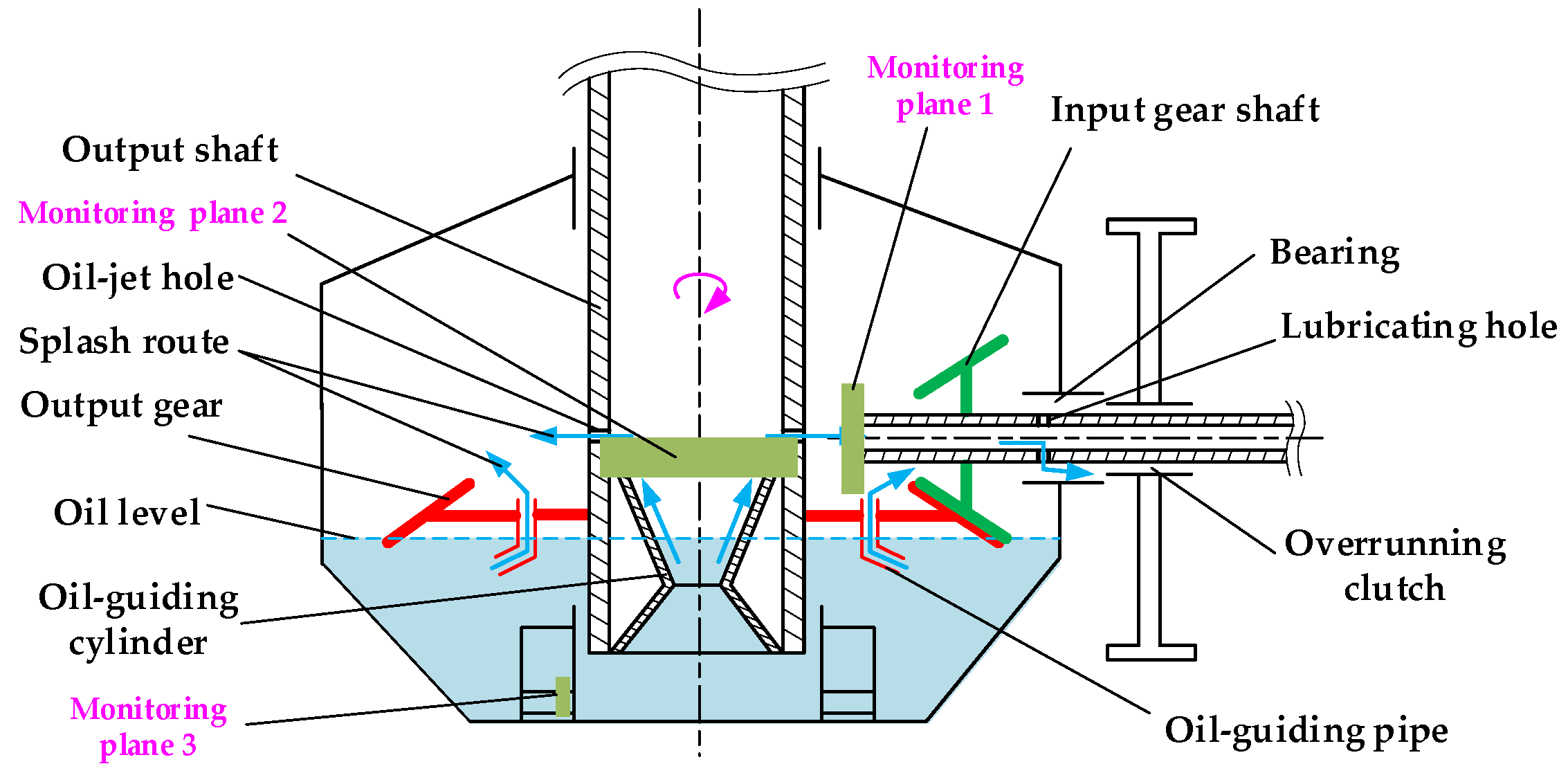
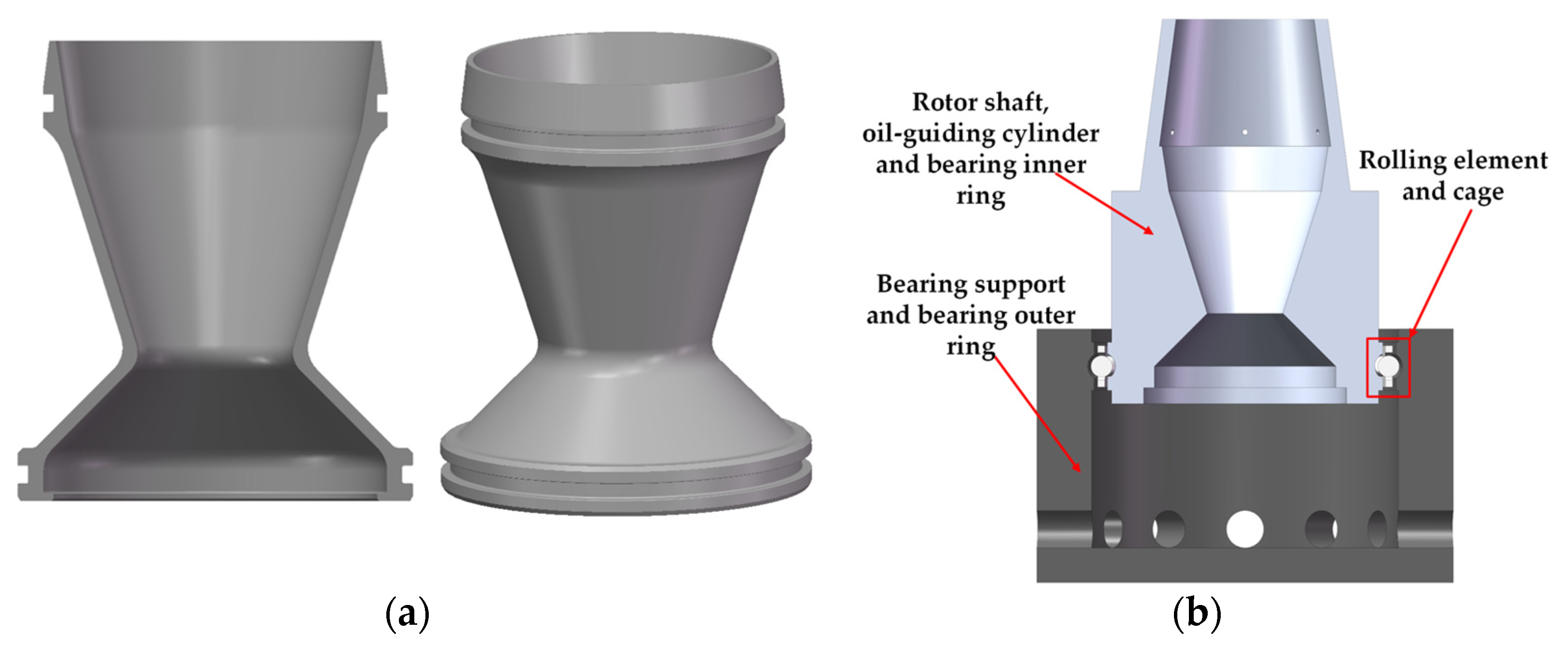
2.2.1. Oil-Guiding Cylinder and Oil-Guiding Splash Lubrication System

As shown in Figure 1, the oil-guiding cylinder in the main reducer of a light helicopter is a double-tapered structure. The upper inverted taper angle is 35°, while the lower taper angle is 90°. The distance from the bottom of the oil-guiding cylinder to the bottom of the oil pool is 15 mm. The three-dimensional model is established in Figure 2a.
To simplify the simulation setup, improve the mesh quality, and reduce the computational load, the oil-guiding cylinder, rotor shaft, and bearing inner ring in Figure 1 are simplified and modeled as a part, the bearing support and bearing outer ring is modeled as a part, and the rolling element and cage are regarded as a part. The simplified geometric model is shown in Figure 2b.

2.2.2. Flow Monitoring Plane

To monitor the flow rate passing through the hollow shaft and determine the performance of the oil-guiding cylinder, three flow monitoring planes are defined with the parameters listed in Table 1 below.

2.3. CFD Grid Technology

The fractional area/volume obstacle method is very effective for incorporating geometric effects into the governing equations. Like all discrete methods, it is still severely limited by the resolution of the computational grid. In this paper, the calculation domain of fluid for the oil-guiding cylinder is divided into uniform hexahedral mesh types, and the oil bath of 200 mm in length, 200 mm in width, and 105 mm in height is established to avoid the interference caused by insufficient oil supply. The number of total cells is set to 4,000,000, as shown in Figure 3. The number of total cells in the fluid domain under this mesh generation scheme is 4,012,910, and the mesh quality is good.
As for the CFD model of the oil-guiding splash lubrication system, the calculation domain of fluid is also divided into uniform hexahedral mesh types, and the oil bath of 200 mm in length, 200 mm in width, and 170 mm in height is developed. The calculation domain Block 1 from −40 mm to 130 mm is regarded as an overall grid zone. The oil-jet hole domain Block 2 of 80 mm in length, 80 mm in width, and 116.5–121 mm in height is locally refined. The size of cells is 1 mm. The number of total cells and local refined cells is set to 8,000,000 and 500,000, respectively. After this mesh generation scheme, the actual number of total cells in the fluid domain is 8,483,447, and the number of Blocks 1 and 2 is 7,969,259 and 514,188, respectively. The maximum adjacent cell size ratio in three directions in cartesian coordinates is 1, and the mesh quality is good. The boundary type of mesh Block 1 is symmetrical. The implicit pressure solver and viscous stress solver are selected, the second-order algorithm is selected for momentum advection, and the momentum and continuity equations chosen in this paper are solved. The restart data interval is 0.1 s, and the fraction interval is 0.1. The maximum elapsed time interval is 10 s.
To improve the precision and reliability of the CFD investigation results, a grid dependency test is performed. The aforementioned mesh generation scheme is exploited for the oil-guiding splash lubrication system, and the total cells C is set to 3,000,000, 5,000,000, 8,000,000, and 10,000,000. The fluid resisting moment of the rotor shaft, bearing component, and the flow rate through flow Monitoring Plane 2 are taken as the standard of the grid independence test, and Figure 4 depicts the numerical results against the grid number. As shown in Figure 4, the number of total cells appears to have a small effect on the resisting moment of the rotor shaft. As the number is 5,000,000, the resisting moments of bearing components are close to that of 8,000,000 and 10,000,000. As for the flow rate (scatter in Figure 4c) and its 10-point moving average value (line in Figure 4c) passing through Monitoring Plane 2, the flow rates are small, and the errors are large when the number of cells is 3,000,000 or 5,000,000, while the flow rates are very close with the maximum error less than 1.5 mL/s when the number of cells is 8,000,000 or 10,000,000. Balancing the computational accuracy and computational load, the number of total cells in all simulations is set to 8 million in this paper. Aeroshell turbine engine oil 555, a synthetic ester lubricant, is used in this paper. Its density is 0.875 g/cm3, and its viscosity is 0.0233 kg/(m·s) at 40 °C.

3. Numerical Results

In this paper, the influences of typical working conditions, including rotational speed, flight inclination, and oil level on the lubrication performance are mainly discussed.

3.1. Rotational Speed

To analyze the effect of rotational speed on the oil supply of the oil-guiding cylinder, the rotational speed n of the rotor shaft is set to 400 r/min, 530 r/min, and 660 r/min. The fluid resisting moment of the rotor shaft and the oil-guiding cylinder is obtained as in Figure 5. It can be seen from the curve that the rotational speed has a strong impact on the fluid resisting moment. The higher the speed, the larger the fluid resisting moment.
Meanwhile, Figure 6 depicts the change trends of the flow rate (scatter in Figure 6) and its 10-point moving average value (line in Figure 6) passing through flow Monitoring Plane 2 under three different rotational speeds. From the figure, it can be seen that it is extremely difficult for the lubricating oil to reach the top of the oil-guiding cylinder at 400 r/min, and the flow rate is close to zero. Compared with the rotational speed of 530 r/min, the oil reaches the top sooner than that of 660 r/min, and the peak of the flow rate is approximately 20 mL/s at about 0.6 s, while the peak value at 530 r/min just surpasses 1 mL/s at 0.7 s. After 1.5 s, the variation tendency of the flow rate at 660 r/min is much closer to that at 530 r/min, and the average flow rate at 660 r/min is still higher than that at 530 r/min.
For the variation law of the flow rate in the interlocking pore near the bottom of the oil bath, it can be obtained by monitoring the flow rate variation through Plane 3 with time, as is shown in Figure 7. Clearly, the higher the rotational speed, the more intense the flow fluctuation in the interlocking pore, and at the same time, the higher the average value of the flow rate after 1.5 s is.
In addition, the flow rate (scatter in Figure 8) and its integration (oil volume) (line in Figure 8) passing through flow Monitoring Plane 1 under three different rotational speeds against time are shown in Figure 8. The two means the lubricating oil flows through Plane 1 and reaches the input gear, bearings, and spline. The oil volume at 530 r/min and 660 r/min shows a similar trend and slopes, except for time dilation, whereas at 400 r/min, the amount of oil reaching the top of the oil-guiding cylinder is very low, resulting in very little oil passing through Monitoring Plane 1, and the total oil volume is close to zero in this case.
The total oil volume flowing through each monitoring plane obtained by numerical analysis under different speeds is listed in Table 2. The higher the rotational speed, the more the oil volume through the monitoring plane. As for Monitoring Plane 1, the amount of oil at 400 r/min is very small. For Monitoring Plane 2, the total amount of oil reaching the top of the oil-guiding cylinder at 660 r/min is significantly increased compared with that of 530 r/min. For Monitoring Plane 3, the increase in speed is beneficial to the increase in the total amount of oil passing through the interlocking pore. From the above analysis, it can be seen that there is a critical speed between 400 r/min and 530 r/min for oil supply to the oil-guiding cylinder, beyond which the oil can climb to the top of the cylinder in large quantities; otherwise, the lubricating oil will not reach it.

3.2. Flight Inclination

To describe the helicopter flight attitude, Figure 9 defines the positive direction of the flight pitch and roll angles by the right-hand rule. In this case, the main reducer of a helicopter is positioned as shown in Figure 9, with the positive direction of the input shaft pointing from the tail to the nose.
A numerical model with a pitch angle of α = ±15° and roll angle of θ = ±15° is established, and the flow rate and its corresponding integration (oil volume) through Monitoring Plane 1 are obtained as Figure 10. Clearly, the flow rate at the pitch angle of 15° is significantly higher than that at pitch angle −15°, and the flow rate at a roll angle of 15° is also significantly higher than that at a roll angle of −15°. In other words, the total oil volume through the target area is more for a larger pitch angle or roll angle.
Figure 11 shows the flow field distribution characteristic of the oil-guiding cylinder at the pitch angle of 15° and at the moment of 1.5 s. There is no obvious difference between the free liquid surface on both sides of the oil-jet hole, and the shape and thickness of the oil layer formed by the oil climbing along the inside wall of the oil-guiding cylinder are symmetrical about the axis of the rotor shaft. It is suggested that the difference in flow rate caused by the pitch angle and the roll angle is probably caused by gravity and rotation direction. When the oil-throwing direction is inclined to the direction of gravity, the splashed oil volume is greater. Meanwhile, as the rotor shaft rotates with an oil-jet hole moving from high to low, the splashed oil volume is more than that of moving from low to high.
The total amount of oil passing through Monitoring Plane 1 at different flight attitude angles is obtained as shown in Table 3. When the oil-guiding splash lubrication system is tilted to the spin-in side, the amount of oil splashed to the hollow cavity of the input shaft is outstanding larger than that of the non-spin-in side, namely, when the main shaft is rotated counterclockwise and the airframe is tilted to the positive direction of the pitch angle and the positive direction of the roll angle, the effective splashed oil amount is greater. Compared with the flight attitude of α = 0°, θ = 0°, the oil feed volume in the target area at α = 15°, θ = 0° and α = 0°, θ = 15° is closer to that in the level posture. In these three operating conditions, the oil-guiding cylinder is capable of providing sufficient oil for splash lubrication and reaching the saturation value of oil volume under this oil-jet hole structure.

3.3. Oil Level

To discuss the effect of oil level on the oil supply performance of the oil-guiding cylinder, the oil level height D is set to 50 mm, 55 mm, and 60 mm. The time curves of the fluid resisting moment of the rotor shaft and oil-guiding cylinder are as shown in Figure 12. The change trends of the fluid resisting moment with time are basically the same for different oil levels, but the contact area of the cylinder with lubricating oil also depends on oil level heights, resulting in a slight difference of fluid resisting moment, and to be more detailed, the higher the oil level, the larger the fluid resisting moment.
The flow rate (scatter in Figure 13) and its 10-point moving average value (line in Figure 13) passing through flow Monitoring Plane 2 are given in Figure 13. At an oil level of 55 mm and 60 mm, the oil reaches the top of the oil-guiding cylinder at about 0.3 s, and then the flow continues to rise to reach a peak and slowly decreases to be stable. Although the peak of the average flow rate varies greatly, the average flow rate is basically the same when the flow reaches relative stability at about 1.5 s, while for the oil level of 50 mm, the moment that the oil reaches the top, and the peak appears inclines to delay for the oil level of 50 mm. Additionally, the flow rate is clearly lower than that of 55 mm and 60 mm.
As for the fluid field characteristics of the interlocking pore near the bottom, it can be obtained by Monitoring Plane 3 with time, as shown in Figure 14. The flow rate tends to be stable after a fleeting fluctuation. A higher oil level brings a greater fluctuation before 1.5 s, as well as a greater flow rate after 1.5 s. Furthermore, the flow rate and its corresponding time integral (oil volume) flowing through Monitoring Plane 1 are shown in Figure 15. The curves of oil volume at oil levels 55 mm and 60 mm have similar trends and slopes, whereas at 50 mm, the oil volume grows more slowly, and the total oil volume is significantly lower than other high oil levels.
The total oil volume through the flow monitoring plane is further analyzed as listed in Table 4. When the oil level rises, the oil volume of Monitoring Plane 2 changes significantly, while the oil volume of Monitoring Plane 3 is almost unchanged. This means that the oil level has an important effect on the amount of oil passing through the top plane of the oil-guiding cylinder. However, once the oil level drops from 55 mm to 50 mm, the total amount of oil passing through Monitoring Plane 1 decreases from 0.81 mL to 0.23 mL, and the amount of splashed oil reduces. Meanwhile, as the oil level is 55 mm and 60 mm, the amount of oil flowing to the target area is relatively close. In terms of the oil supply at the top of the oil-guiding cylinder, the oil volume increases with the oil level, but the splashed oil volume does not increase significantly. This is due to the oil volume passing through the hole close to the saturation state at this point.

4. Experimental Validation

To verify the reliability and effectiveness of the aforementioned CFD method, the test of oil-guiding splash lubrication under different operating conditions, including speed and oil level is carried out, and the reliability and effectiveness of CFD method are compared and verified by capturing the flow field distribution and monitoring the oil volume.

4.1. Test Rig

The oil-guiding splash lubrication test system consists of a drive motor, a drive system, a testing device, and a testing and controlling system. The drive motor drives the input hollow shaft of the test bevel gearbox through a coupling. The shaft is radially positioned with the bevel gear choosing interference fit, and a removable oil guide tube is installed on the driven gear spoke. The oil-guiding cylinder is positioned inside the hollow shaft by a snap ring, and three oil-jet holes are opened at the top of the hollow shaft and throughout the oil-guiding cylinder. The oil-collecting pipe is installed on the gearbox cover to collect the lubricant oil supplied by the oil-guiding cylinder to flow through the oil-jet hole. The lubricant is collected and measured through the measuring cup below the oil-collecting pipe. The photos of the lubrication test bench have been showed in detail in the open literatures [32].

4.2. Experimental Results

Balancing the experimental conditions and purposes, this paper mainly carried out tests under different rotational speeds and oil levels.

4.2.1. Rotational Speed

Considering the structural demands and operating conditions of the light helicopter, combining the analysis of numerical results that the flow rate is moderate at the oil level height H of 55 mm, lubrication tests were performed with the oil level height H of 55 mm, rotational speed n of 400 r/min, 530 r/min, and 660 r/min, and running time for each test of 5 min. The initial baseline testing was done without an oil-guiding cylinder inside the hollow shaft under each rotational speed or oil level. All measured experimental and numerical flow data are compared in Table 5. It is indicated that after increasing the speed, the splash of oil was more intense, the oil-collecting pipe collected a large amount of splash of oil not through an oil-jet hole, and the increase in speed contributed to increasing the splash of oil to the target area. At low speed, the increase in the experimental oil volume with the speed is larger than the corresponding simulation. This is due to the discrepancy between the simplified numerical model and the actual gearing system. Nevertheless, with the rotational speed of 400 r/min, 530 r/min, and 660 r/min, the error between the experimental net oil-collecting volume (i.e., target oil volume in Table 5) and the numerical oil volume is 20.0%, 13.6%, and 9.2%. Experiments show a good agreement with numerical results. It also verified the proposed CFD method is valid and effective.

4.2.2. Oil Level

The rotational speed of 530 r/min is maintained, and there is an oil level height H change of 45 mm, 55 mm, and 65 mm. The running time of each test is still 5 min. All measured experimental and numerical flow data are compared in Table 6. Three oil level heights corresponded to the low, medium, and high oil levels, and the collection of oil volume at high oil levels was larger, reaching 17.3 mL. There was no obvious splash of oil in the oil-jet hole at low oil level, while the splash of oil was intense at a high oil level, but most of the oil that splashed into the oil-collecting pipe came from the churning behavior of the shaft and gear. Both numerical and experimental data show that the amount of oil in the target area increases with the oil level. The rotating gear churns the oil very violently, so a higher oil level height contributes to more oil splashed from the gear surface into the oil-collecting tube, along with a larger amount of disturbed oil volume, namely, the amount of oil in the baseline testing increases with the increase in oil level. Nevertheless, with the oil level of 45 mm, 55 mm, and 65 mm, the error between the experimental net oil-collecting volume (i.e., target oil volume in Table 6) and the numerical oil volume is 10.0%, 13.6%, and 12.6%. Again, the experiments show good matching with the numerical results. It also verified the proposed CFD method is valid and effective. The results show that the increase in oil level or the increase in speed increases the amount of splashing oil.

5. Conclusions

In this paper, a new type of lubrication system in the main reducer of a light helicopter is investigated. The effect of the oil-guiding cylinder on the lubrication performance of this special lubrication system under different operating conditions was analyzed. Meanwhile, lubrication tests were carried out by setting up a specific test rig for oil-guiding splash lubrication under different rotational speeds and oil levels. The difference between experimental oil volume and numerical results is less than 20.0% and no more than 14% for most of them. The main conclusions can be drawn as follows:
  • The increase in rotational speed makes the flow rate of baseline testing rise, and the amount of oil splashed to the oil-collecting pipe is greatly increased, resulting in a larger increase in oil volume. There is a critical speed between 400 r/min and 530 r/min, beyond which the oil can climb to the top of the oil-guiding cylinder in large quantities; if not, the continuous oil supply cannot be realized.
  • The amount of oil passing through the target area increases with the oil level. The higher the oil level height, the more oil is splashed into the oil-collecting tube from the gear surface. From the oil supply at the top of the oil-guiding cylinder, the oil supply increases when the oil level rises, but the amount of oil is not significantly elevated. At this point, the amount of oil flowing through the oil-jet hole has reached saturation point. Balancing the resisting moment and the flow rate, the oil level height H = 55 mm is the best choice.
  • The difference in flow rate caused by the pitch angle and the roll angle is mainly due to gravity and rotation direction. When the direction of oil throwing is inclined to the gravity direction, the splash of oil volume is higher. When the rotor shaft is rotating, the splash of oil volume is higher as the oil-jet hole moves from high to low than that of moving from low to high.

Author Contributions

Conceptualization, M.Y. and D.Y.; methodology, X.C.; software, L.X.; validation, L.X.; formal analysis, L.X.; investigation, X.C.; resources, Y.D.; data curation, X.C.; writing—original draft preparation, X.C.; writing—review and editing, X.Z.; visualization, X.Z.; supervision, Y.D.; project administration, Y.D.; funding acquisition, Y.D. All authors have read and agreed to the published version of the manuscript.

Funding

This research was funded by the National Defense Preliminary Research Project of China, Grant Number KY-1044-2020-0657.

Acknowledgments

We would like to express our thanks to the editors of Aerospace and the anonymous reviewers for their work in processing this article.

Conflicts of Interest

The authors declare no conflict of interest.

References

  1. Seetharaman, S.; Kahraman, A.; Moorhead, M.D.; Petry-Johnson, T.T. Oil Churning Power Losses of a Gear Pair: Experiments and Model Validation. J. Tribol. 2009, 131, 022202. [Google Scholar] [CrossRef]
  2. Neurouth, A.; Changenet, C.; Ville, F.; Octrue, M.; Tinguy, E. Experimental Investigations to Use Splash Lubrication for High-Speed Gears. J. Tribol. 2017, 139, 061104. [Google Scholar] [CrossRef]
  3. Casseau, V.; Espinoza, D.E.R.; Scanlon, T.J.; Brown, R.E. A Two-Temperature Open-Source CFD Model for Hypersonic Reacting Flows, Part Two: Multi-Dimensional Analysis. Aerospace 2016, 3, 45. [Google Scholar] [CrossRef] [Green Version]
  4. Youssefi, M.R.; Knight, D. Assessment of CFD Capability for Hypersonic Shock Wave Laminar Boundary Layer Interactions. Aerospace 2017, 4, 25. [Google Scholar] [CrossRef]
  5. Samad, A.; Villeneuve, E.; Morency, F.; Volat, C. A Numerical and Experimental Investigation of the Convective Heat Transfer on a Small Helicopter Rotor Test Setup. Aerospace 2021, 8, 53. [Google Scholar] [CrossRef]
  6. Moshammer, T.; Mayr, F.; Kargl, K.; Honeger, C. Simulation of Oil Flow in Gear Box Housing. SAE Tech. Pap. Ser. 2006, 1, 1574. [Google Scholar] [CrossRef]
  7. Concli, F.; Torre, A.D.; Gorla, C.; Montenegro, G. A New Integrated Approach for the Prediction of the Load Independent Power Losses of Gears: Development of a Mesh-Handling Algorithm to Reduce the CFD Simulation Time. Adv. Tribol. 2016, 2016, 2957151. [Google Scholar] [CrossRef]
  8. Concli, F.; Gorla, C. Numerical modeling of the power losses in geared transmissions: Windage, churning and cavitation simulations with a new integrated approach that drastically reduces the computational effort. Tribol. Int. 2016, 103, 58–68. [Google Scholar] [CrossRef]
  9. Concli, F.; Gorla, C. Numerical modeling of the churning power losses in planetary gearboxes: An innovative partitioning-based meshing methodology for the application of a computational effort reduction strategy to complex gearbox configurations. Lubr. Sci. 2017, 29, 455–474. [Google Scholar] [CrossRef]
  10. Liu, H.; Jurkschat, T.; Lohner, T.; Stahl, K. Determination of oil distribution and churning power loss of gearboxes by finite volume CFD method. Tribol. Int. 2017, 109, 346–354. [Google Scholar] [CrossRef]
  11. Liu, H.; Arfaoui, G.; Stanić, M.; Montigny, L.; Jurkschat, T.; Lohner, T.; Stahl, K. Numerical modelling of oil distribution and churning gear power losses of gearboxes by smoothed particle hydrodynamics. Proc. Inst. Mech. Eng. Part J. J. Eng. Tribol. 2018, 233, 74–86. [Google Scholar] [CrossRef]
  12. Liu, H.; Jurkschat, T.; Lohner, T.; Stahl, K. Detailed Investigations on the Oil Flow in Dip-Lubricated Gearboxes by the Finite Volume CFD Method. Lubricants 2018, 6, 47. [Google Scholar] [CrossRef] [Green Version]
  13. Hu, X.; Jiang, Y.; Luo, C.; Feng, L.; Dai, Y. Churning power losses of a gearbox with spiral bevel geared transmission. Tribol. Int. 2019, 129, 398–406. [Google Scholar] [CrossRef]
  14. Jiang, Y.; Hu, X.; Hong, S.; Li, P.; Wu, M. Influences of an oil guide device on splash lubrication performance in a spiral bevel gearbox. Tribol. Int. 2019, 136, 155–164. [Google Scholar] [CrossRef]
  15. Hu, X.; Wang, A.; Li, P.; Wang, J. Influence of dynamic attitudes on oil supply for bearings and churning power losses in a splash lubricated spiral bevel gearbox. Tribol. Int. 2021, 159, 106951. [Google Scholar] [CrossRef]
  16. Changenet, C.; Velex, P. A Model for the Prediction of Churning Losses in Geared Transmissions—Preliminary Results. J. Mech. Des. 2006, 129, 128–133. [Google Scholar] [CrossRef]
  17. Changenet, C.; Velex, P. Housing Influence on Churning Losses in Geared Transmissions. J. Mech. Des. 2008, 130, 062603. [Google Scholar] [CrossRef]
  18. Changenet, C.; Leprince, G.; Ville, F.; Velex, P. A Note on Flow Regimes and Churning Loss Modeling. J. Mech. Des. 2011, 133, 121009. [Google Scholar] [CrossRef]
  19. Quiban, R.; Changenet, C.; Marchesse, Y.; Ville, F.; Belmonte, J. Churning losses of spiral bevel gears at high rotational speed. Proc. Inst. Mech. Eng. Part J. J. Eng. Tribol. 2019, 234, 172–182. [Google Scholar] [CrossRef]
  20. Dai, Y.; Ma, F.; Zhu, X.; Ouyang, B. Development of an analytical model to estimate the churning power losses of a spiral bevel gear. Tribol. Int. 2020, 151, 106536. [Google Scholar] [CrossRef]
  21. Lu, F.; Wang, M.; Bao, H.; Huang, W.; Zhu, R. Churning power loss of the intermediate gearbox in a helicopter under splash lubrication. Proc. Inst. Mech. Eng. Part J. J. Eng. Tribol. 2021. [Google Scholar] [CrossRef]
  22. Wang, Y.; Niu, W.; Wei, S.; Song, G. Influence of spin flow on lubricating oil jet—Design method of oil spray parameters to high speed spur gears. Tribol. Int. 2015, 92, 290–300. [Google Scholar] [CrossRef]
  23. Wang, Y.; Song, G.; Niu, W.; Chen, Y. Influence of oil injection methods on the lubrication process of high speed spur gears. Tribol. Int. 2018, 121, 180–189. [Google Scholar] [CrossRef]
  24. Wang, Y.; Song, G.; Niu, W.; Chen, Y. Optimized design of spray parameters of oil jet lubricated spur gears. Tribol. Int. 2018, 120, 149–158. [Google Scholar] [CrossRef]
  25. Dai, Y.; Wu, W.; Zhou, H.B.; Zhang, J.; Ma, F.Y. Numerical Simulation and Optimization of Oil Jet Lubrication for Rotorcraft Meshing Gears. Int. J. Simul. Model. 2018, 17, 318–326. [Google Scholar] [CrossRef]
  26. Dai, Y.; Jia, J.; Ouyang, B.; Bian, J. Determination of an Optimal Oil Jet Nozzle Layout for Helical Gear Lubrication: Mathematical Modeling, Numerical Simulation, and Experimental Validation. Complexity 2020, 2020, 2187027. [Google Scholar] [CrossRef]
  27. Dai, Y.; Ma, F.; Zhu, X.; Su, Q.; Hu, X. Evaluation and optimization of the oil jet lubrication performance for orthogonal face gear drive: Modelling, simulation and experimental validation. Energies 2019, 12, 1935. [Google Scholar] [CrossRef] [Green Version]
  28. Zhu, X.; Dai, Y.; Ma, F.; Ouyang, B. Mathematical modeling and numerical simulation for determining an optimized oil jet layout for spiral bevel gear lubrication. Proc. Inst. Mech. Eng. Part J. J. Eng. Tribol. 2021, 235, 611–628. [Google Scholar] [CrossRef]
  29. Fondelli, T.; Andreini, A.; Da Soghe, R.; Facchini, B.; Cipolla, L. Numerical Simulation of Oil Jet Lubrication for High Speed Gears. Int. J. Aerosp. Eng. 2015, 2015, 752457. [Google Scholar] [CrossRef]
  30. Fondelli, T.; Andreini, A.; Da Soghe, R.; Facchini, B.; Cipolla, L. Volume of fluid (VOF) analysis of oil-jet lubrication for high-speed spur gears using an adaptive meshing approach. In Proceedings of the ASME Turbo Expo 2015: Turbine Technical Conference and Exposition, Montreal, QC, Canada, 15–19 June 2015. [Google Scholar] [CrossRef]
  31. Massini, D.; Fondelli, T.; Facchini, B.; Tarchi, L.; Leonardi, F. High Speed Visualizations of oil Jet Lubrication for Aero-engine Gearboxes. Energy Procedia 2016, 101, 1248–1255. [Google Scholar] [CrossRef]
  32. Yin, M.; Xu, L.J.; Dai, Y.; Yang, D.; Zhu, X. Flow Characteristics of Oil-Guiding Splash Lubrication: Simulation and Experiment Studies. Int. J. Simul. Model. 2021, 20, 363–374. [Google Scholar] [CrossRef]
  33. Wang, T.; Guo, Y.; Wang, G.; Wang, X. Detection and analysis of metal scrap in lubricating oil based on wear fault of spindle bearing of turboshaft engine. Vibroeng. Procedia 2021, 38, 32–37. [Google Scholar] [CrossRef]
  34. Wróblewski, P. Analysis of Torque Waveforms in Two-Cylinder Engines for Ultralight Aircraft Propulsion Operating on 0W-8 and 0W-16 Oils at High Thermal Loads Using the Diamond-Like Carbon Composite Coating. SAE Int. J. Engines 2021, 15, 2022. [Google Scholar] [CrossRef]
  35. Wróblewski, P.; Koszalka, G. An Experimental Study on Frictional Losses of Coated Piston Rings with Symmetric and Asymmetric Geometry. SAE Int. J. Engines 2021, 14, 853–866. [Google Scholar] [CrossRef]
Figure 1. Schematic diagram of a helicopter main reducer oil-guiding splash lubrication system.
Aerospace 08 00345 g001
Figure 2. Three-dimensional modeling: (a) oil guide; (b) splash lubrication system.
Aerospace 08 00345 g002
Figure 3. Grid of the case.
Aerospace 08 00345 g003
Figure 4. Resisting moment and flow rate–time curves against total cells: (a) resisting moment of rotor shaft; (b) resisting moment of bearing components; (c) flow rate and its 10-point moving average value (Monitoring Plane 2).
Aerospace 08 00345 g004aAerospace 08 00345 g004b
Figure 5. Fluid resisting moment–time curve.
Aerospace 08 00345 g005
Figure 6. Oil flow rate–time curve (Monitoring Plane 2).
Aerospace 08 00345 g006
Figure 7. Oil flow rate–time curve (Monitoring Plane 3).
Aerospace 08 00345 g007
Figure 8. Oil flow rate–oil volume–time curve (Monitoring Plane 1).
Aerospace 08 00345 g008
Figure 9. Definition of flight pitch and roll angles.
Aerospace 08 00345 g009
Figure 10. Flow rate–oil volume–time curves (Monitoring Plane 1).
Aerospace 08 00345 g010
Figure 11. Cross-section of flow field distribution (α = 15°, t = 1.5 s).
Aerospace 08 00345 g011
Figure 12. Change rules of fluid resisting moment versus time.
Aerospace 08 00345 g012
Figure 13. Change rules of flow rate moment versus time (Monitoring Plane 2).
Aerospace 08 00345 g013
Figure 14. Change rules of flow rate moment versus time (Monitoring Plane 3).
Aerospace 08 00345 g014
Figure 15. Change rules of flow rate and oil volume versus time (Monitoring Plane 1).
Aerospace 08 00345 g015
Table 1. Parameters of monitoring plane.
Monitoring Planesx-Direction (mm)y-Direction (mm)z-Direction (mm)
1x = 70yL = −15, yH = 15zL = 105, zH = 135
2xL = −33, xH = 33yL = −33, yH = 33z = 113
3x = −70yL = −8, yH = 8zL = −38, zH = −22
Table 2. Total oil volume through the monitoring planes versus rotational speed.
Rotating Speed (r/min)Oil Volume of Monitoring Plane 1 (mL)Oil Volume of Monitoring Plane 2 (mL)Oil Volume of Monitoring Plane 3 (mL)
4000.0430.1124.40
5300.8219.6628.24
6601.0428.9733.10
Table 3. Total oil quantity at different flight attitudes (Monitoring Surface 1).
ParametersTotal Oil Volume (mL)Direction of Tilt
α = 15°, θ = 0°0.80041Spin-in side
α = −15°, θ = 0°0.48555Spin-out side
α = 0°, θ = 0°0.81169Level
α = 0°, θ = 15°0.85675Spin-in side
α = 0°, θ = −15°0.54695Spin-out side
Table 4. Total oil volume versus oil level.
Oil Level (mm)Oil Volume of Monitoring Plane 1 (mL)Oil Volume of Monitoring Plane 2 (mL)Oil Volume of Monitoring Plane 3 (mL)
500.2313.1227.68
550.8119.6628.24
600.7122.9129.19
Table 5. Experimental and numerical flow data versus rotating speed.
Rotating Speed n
(r/min)
RunningTime (min)Experimental Oil Volume (mL)Baseline
Testing Oil
Volume (mL)
Target Oil Volume (mL)Numerical Oil Volume (mL)Error
40050.50.40.10.1220.0%
53054.41.92.52.1613.6%
660510.27.72.52.279.2%
Table 6. Experimental and numerical flow data versus oil level.
Oil Level H
(mm)
Running Time (min)Experimental Oil Volume (mL)Baseline Testing Oil Volume (mL)Target Oil Volume (mL)Numerical Oil Volume (mL)Error
4550.70.60.10.0910.0%
5554.41.92.52.1613.6%
65517.314.23.13.4912.6%
Publisher’s Note: MDPI stays neutral with regard to jurisdictional claims in published maps and institutional affiliations.

