UWE-4: First Electric Propulsion on a 1U CubeSat—In-Orbit Experiments and Characterization


Abstract
1. Introduction
2. UWE-4
2.1. Satellite Design
2.2. NanoFEEP Propulsion System
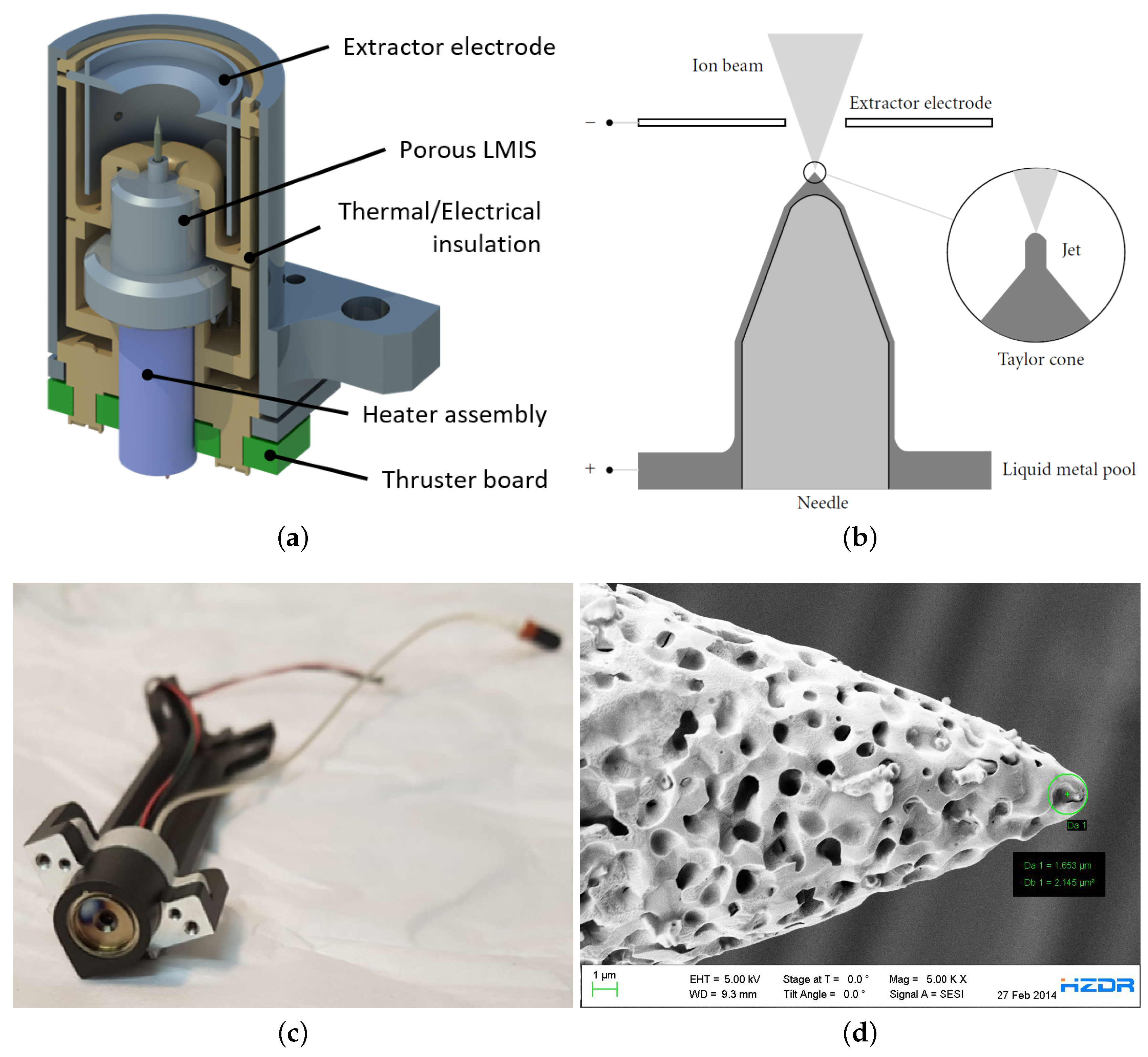
2.2.1. NanoFEEP Thruster
2.2.2. Neutralizer
2.2.3. Power Processing Unit
2.2.4. Precautions Due to the Propulsion System
- Both PPUs are facing each other with the same side as shown in Figure 2, which houses the power conversion stage, since the power conversion may create electromagnetic interference effects in the satellite. This way the internal ground layer in the printed circuit board shields the electronics of the rest of the satellite.
- The power conversion stages are potted for improved isolation.
- The thrusters and the neutralizers are connected to the PPU with dedicated HV cables and are not put on the bus with all the other signals and power lines of the satellite, in order to secure the satellite bus from the HV. The heaters are also connected with a dedicated harness.
- The antennas of the radio communication subsystem are partially in the plumes of thrusters A and D. This could lead to charging of the antennas, since transceivers are usually equipped with direct current blocking capacitors at the output. However, during the planning phase of UWE-4, the authors decided to stay with this design in favor of a well-tested and flight-proven communication system. To mitigate charging effects of the antennas, an antenna bleeder resistor of 50 k is installed between antenna and ground potential. This enables the antennas to slowly discharge any static charge, but does not affect the 50 impedance. An experimental test of the transmission capability of the transceivers after exposition as well as a measurement of the received signal strength indication of the transceivers during exposition to the thrusters’ plasma plume proved the design prior to launch. Neither the communication system nor any other part of the satellite indicates any harmful effects due to the exposition to the thrusters’ plasma plume.
- The plumes of thrusters A and D can also partially hit the lids of the antenna deployment system. Thus, the design of the lids was adjusted. On one side they need to be conducting for the ion charge hitting the lid to be compensated, on the other side they need to be insulating to the antennas (refer to the top left corner of Figure 4c). Thus, they are produced of aluminum with an additional distance piece to the antenna made of Teflon.
- Moreover, several software components were implemented in order to detect possible upcoming failures of the power conversion stages, the thrusters or the neutralizers that could lead to spacecraft charging or to damage at any component.
3. Analysis Methodology
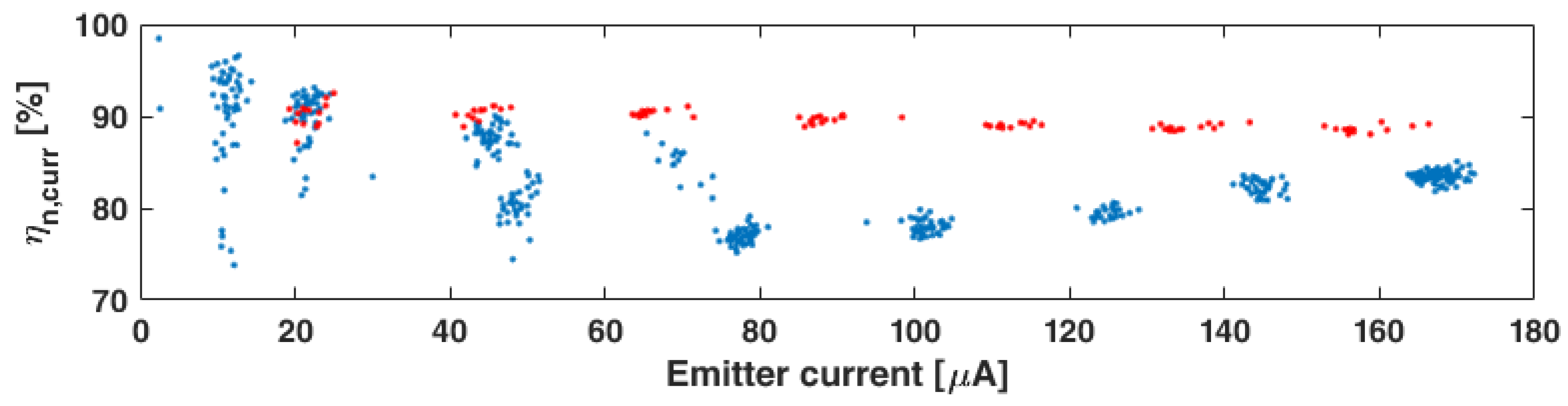
3.1. Thruster and Neutralizer Performance
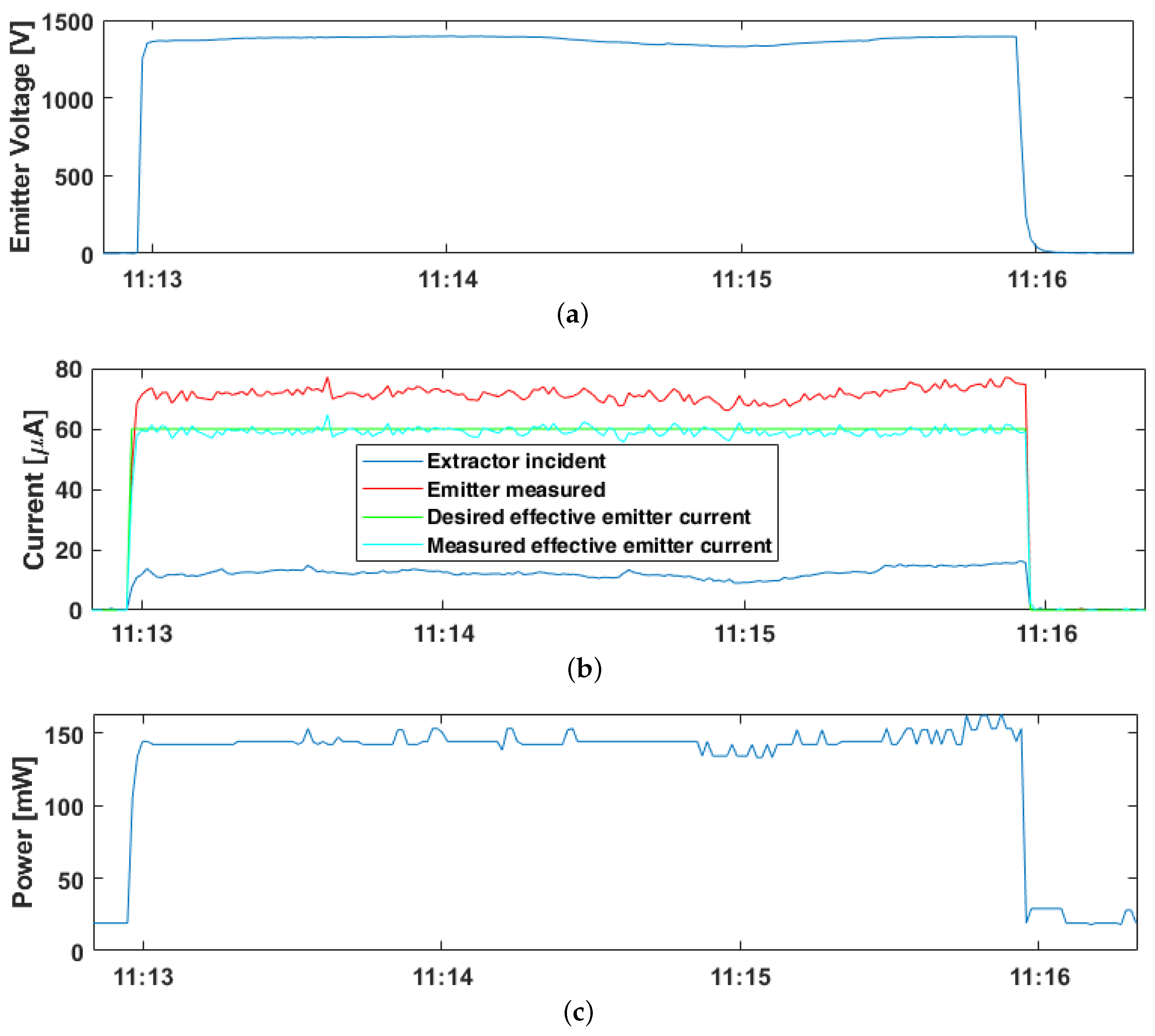
- : The HV supplied between emitter of the thruster head or the silicon chip of the neutralizer and the respective extractor.
- : The desired current to be ejected by the thruster head or the neutralizer.
- : The electrical current supplied to the needle of the emitter or the silicon chip of the neutralizer respectively. This current is being emitted, but might be intercepted by the extractor before actually leaving the spacecraft.
- : The electrical current intercepted by the extractor of the thruster or the neutralizer and thus returning to the spacecraft.
3.2. Thrust Estimation
4. Results
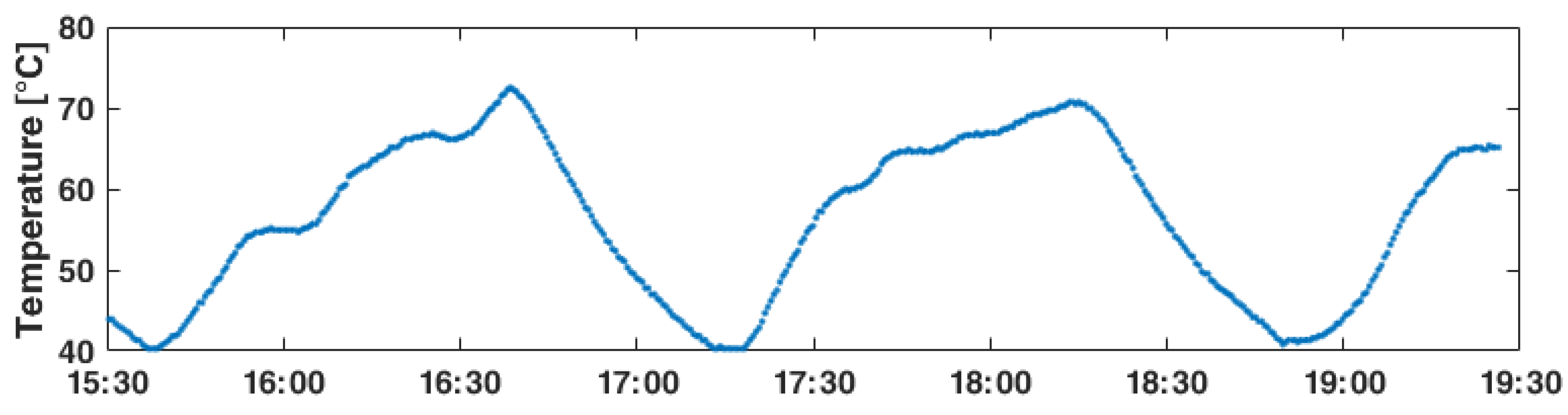
4.1. Heater
4.2. Neutralizer
4.3. Thruster
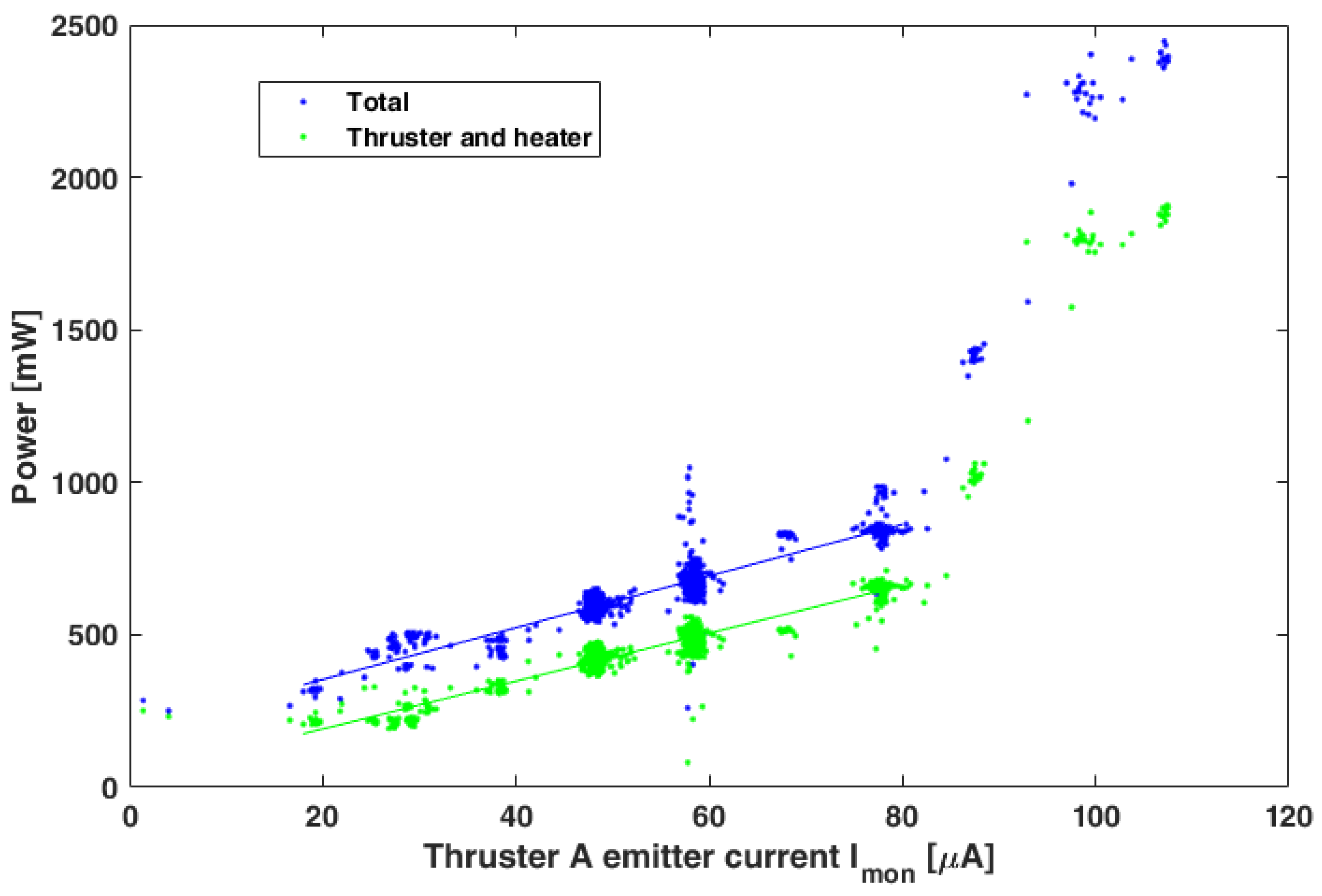
4.3.1. Thruster A
4.3.2. Thruster B
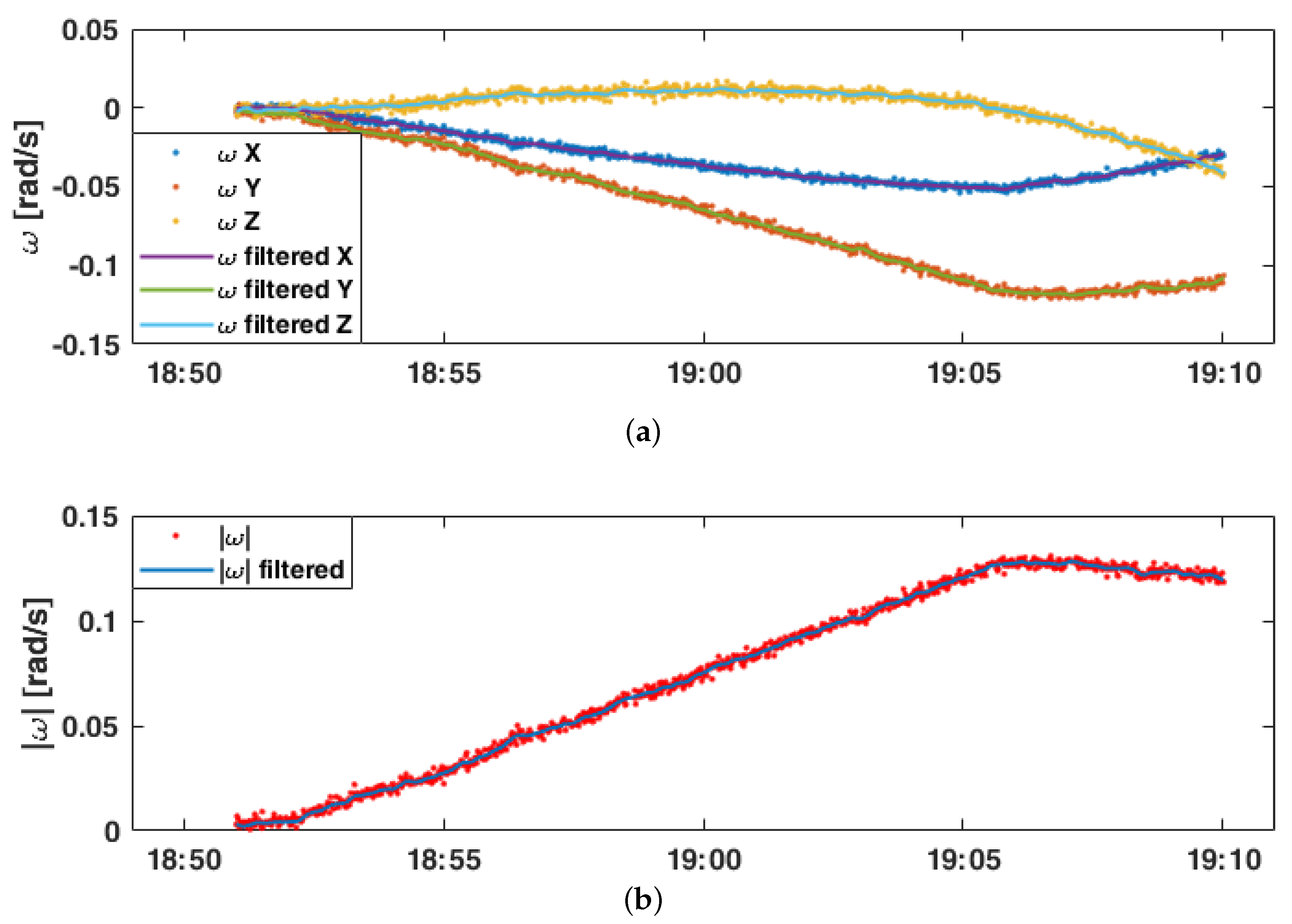
4.4. Thrust Estimation of Both Thrusters
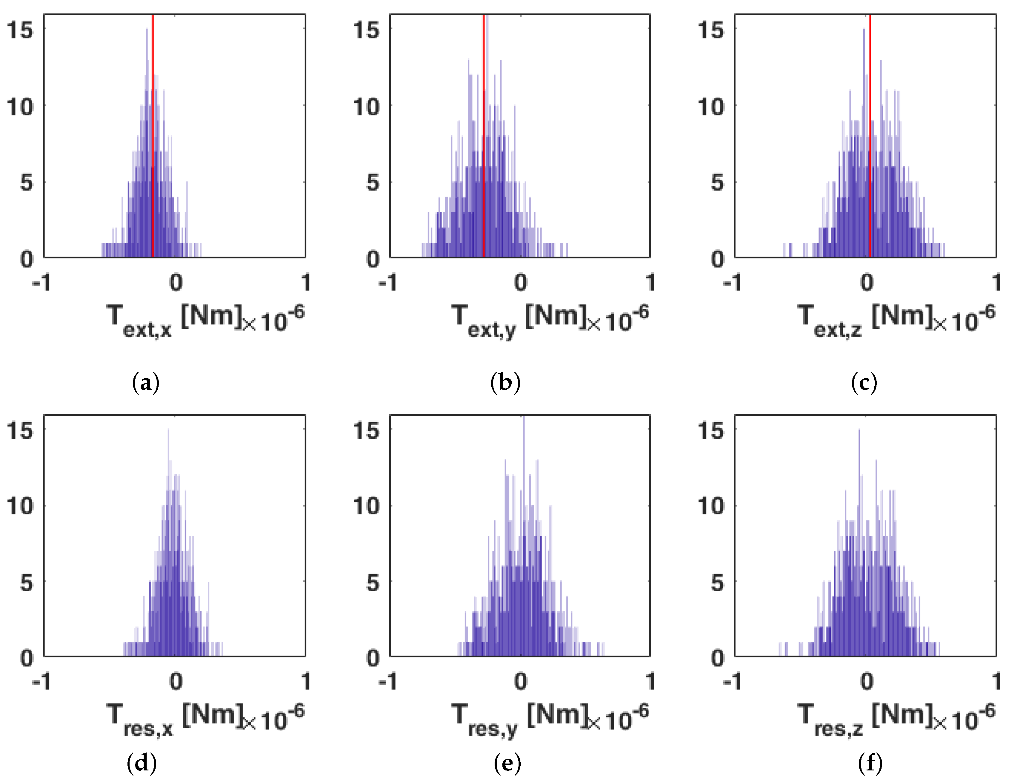
- The analysis is based on the measurement of the created torque. However, the thrust vector is not perpendicular to the position vector of the thruster heads. Thus, only a small fraction of the thrust effectively contributes to the torque and as shown in Figure 15 and Equation (15), the uncertainty of torque estimation is of the same magnitude as the result itself.
- Experiments of longer duration and with stronger thrusts could potentially decrease the effects of noise. However, the precession term in the Euler equation would become more dominant, which would make the optimization less accurate.
5. Conclusions
Author Contributions
Funding
Acknowledgments
Conflicts of Interest
Abbreviations
| AOCS | Attitude and Orbit Control System |
| CAD | Computer-Aided Design |
| CNT | Carbon Nanotube |
| CoG | Center of Gravity |
| FEEP | Field-emission electric propulsion |
| HV | High voltage |
| PPU | Power Processing Unit |
| UNISEC | University Space Engineering Consortium |
| UWE | University Wuerzburg Experimental satellite |
References
- Schilling, K. Design of pico-satellites for education in systems engineering. IEEE Aerosp. Electron. Syst. Mag. 2006, 21, 9–14. [Google Scholar] [CrossRef]
- Schilling, K. Perspectives for miniaturized, distributed, networked cooperating systems for space exploration. Robot. Auton. Syst. 2017, 90, 118–124. [Google Scholar] [CrossRef]
- Schmidt, M.; Ravandoor, K.; Kurz, O.; Busch, S.; Schilling, K. Attitude Determination for the Pico-Satellite UWE-2. In Proceedings of the 17th IFAC World Congress, Seoul, Korea, 6–11 July 2008. [Google Scholar]
- Busch, S.; Bangert, P.; Dombrovski, S.; Schilling, K. UWE-3, in-orbit performance and lessons learned of a modular and flexible satellite bus for future pico-satellite formations. Acta Astronaut. 2015, 117, 73–89. [Google Scholar] [CrossRef]
- Gibbon, D.; Underwood, C.; Sweeting, M.; Amri, R. Cost effective propulsion systems for small satellites using butane propellant. Acta Astronaut. 2002, 51, 145–152. [Google Scholar] [CrossRef]
- Sarda, K. Canadian Advanced Nanospace Experiment 2 Orbit Operations: Two Years of Pushing the Nanosatellite Performance Envelope. In Proceedings of the 38th COSPAR Scientific Assembly, Bremen, Germany, 18–25 July 2010; Volume 38, p. 2. [Google Scholar]
- Bock, D.; Kramer, A.; Bangert, P.; Schilling, K.; Tajmar, M. NanoFEEP on UWE platform—Formation Flying of CubeSats using Miniaturized Field Emission Electric Propulsion Thrusters. In Proceedings of the Joint Conference of 30th International Symposium on Space Technology and Science, 34th International Electric Propulsion Conference and 6th Nano-satellite Symposium, Hyogo-Kobe, Japan, 4–10 July 2015. [Google Scholar]
- Bock, D.; Kramer, A.; Bangert, P.; Schilling, K.; Tajmar, M. NanoFEEP—Highly Miniaturized FEEP Propulsion System for Attitude and Orbit Control of CubeSats. In Proceedings of the 5th Space Propulsion Conference, Rome, Italy, 2–6 May 2016. [Google Scholar]
- Bangert, P.; Dombrovski, S.; Kramer, A.; Schilling, K. UWE-4: Advances in the Attitude and Orbit Control of a Pico-Satellite. In Proceedings of the 4S Symposium, Valletta, Malta, 30 May–3 June 2016. [Google Scholar]
- Dombrovski, S.; Bangert, P. Introduction of a new Sandbox Interpreter Approach for Advanced Satellite Operations and Safe On-Board Code Execution. In Proceedings of the 66th International Astronautical Congress, Jerusalem, Israel, 12–16 October 2015. [Google Scholar]
- California Polytechnic State University. CubeSat Design Specification Rev. 13, The CubeSat Program. Available online: https://static1.squarespace.com/static/5418c831e4b0fa4ecac1bacd/t/56e9b62337013b6c063a655a/1458157095454/cds_rev13_final2.pdf (accessed on 24 June 2020).
- Kramer, A.; Bangert, P.; Paries, F.; Schilling, K. Preparations for Orbit control on the Pico-Satellite UWE-4. In Proceedings of the 11th IAA Symposium on Small Satellites for Earth Observation, Berlin, Germany, 24–28 April 2017. [Google Scholar]
- Tajmar, M.; Scharlemann, C. Development of Electric and Chemical Microthrusters. Int. J. Aerosp. Eng. 2011, 2011. [Google Scholar] [CrossRef]
- Bock, D.; Bethge, M.; Tajmar, M. Highly miniaturized FEEP thrusters for CubeSat applications. In Proceedings of the 4th Space Propulsion Conference, Cologne, Germany, 19–22 May 2014. [Google Scholar]
- Haynes, W.M. (Ed.) Handbook of Chemistry and Physics, 95th ed.; CRC Press: Boca Raton, FL, USA, 2014. [Google Scholar]
- Sutton, G. Rocket Propulsion Elements: An Introduction to the Engineering of Rockets; Wiley-Interscience Publication: Hoboken, NJ, USA, 1986. [Google Scholar]
- Malina, F.J. Characteristics of the rocket motor unit based on the theory of perfect gases. J. Frankl. Inst. 1940, 230, 433–454. [Google Scholar] [CrossRef]
- Bock, D.; Spethmann, A.; Trottenberg, T.; Kersten, H.; Tajmar, M. In-plume thrust measurement of NanoFEEP thruster with a force measuring probe using laser interferometry. In Proceedings of the 35th International Electric Propulsion Conference, Atlanta, GA, USA, 8–12 October 2017. [Google Scholar]
- Tribble, A. The Space Environment—Implications for Spacecraft Design; Princeton University Press: Princeton, NJ, USA, 2003. [Google Scholar]
- Bock, D.; Tajmar, M. Highly miniaturized FEEP propulsion system (NanoFEEP) for attitude and orbit control of CubeSats. Acta Astronaut. 2018, 144, 422–428. [Google Scholar] [CrossRef]
- Tajmar, M.; Stämm, S. MEMS-Based Gas-Field-Ion-Source for Micro Thruster and Gas Sensor Application. In Proceedings of the 4th Space Propulsion Conference, Cologne, Germany, 19–22 May 2014. [Google Scholar]
- UNISEC Europe. CubeSat Subsystem Interface Definition. Available online: http://unisec-europe.eu/standards/bus/ (accessed on 24 June 2020).
- Bangert, P. Magnetic Attitude Control of Miniature Satellites and Its Extension towards Orbit Control Using an Electric Propulsion System. Ph.D. Thesis, Julius-Maximilians-University, Wuerzburg, Germany, 2018. [Google Scholar]
- Pavel Holoborodko. Smooth Noise-Robust Differentiators. Available online: http://www.holoborodko.com/pavel/numerical-methods/numerical-derivative/smooth-low-noise-differentiators/ (accessed on 15 June 2020).
- Lagarias, J.; Reeds, J.; Wright, M.; Wright, P. Convergence Properties of the Nelder–Mead Simplex Method in Low Dimensions. SIAM J. Optim. 1998, 9, 112–147. [Google Scholar] [CrossRef]


| Time Range | Active Components | Total Power Consumption [mW] |
|---|---|---|
| 09:58:50–09:58:55 | Heater A & B | |
| 09:58:56–09:58:59 | Heater A | |
| 09:59:00–09:59:30 | Heater A | 412–459 |
| Thruster A | ||
| Neutralizer A | ||
| 09:59:31–09:59:39 | Heater A |
| Angle | Thruster A | Thruster B |
|---|---|---|
© 2020 by the authors. Licensee MDPI, Basel, Switzerland. This article is an open access article distributed under the terms and conditions of the Creative Commons Attribution (CC BY) license (http://creativecommons.org/licenses/by/4.0/).
Share and Cite
Kramer, A.; Bangert, P.; Schilling, K. UWE-4: First Electric Propulsion on a 1U CubeSat—In-Orbit Experiments and Characterization. Aerospace 2020, 7, 98. https://doi.org/10.3390/aerospace7070098
Kramer A, Bangert P, Schilling K. UWE-4: First Electric Propulsion on a 1U CubeSat—In-Orbit Experiments and Characterization. Aerospace. 2020; 7(7):98. https://doi.org/10.3390/aerospace7070098
Chicago/Turabian StyleKramer, Alexander, Philip Bangert, and Klaus Schilling. 2020. "UWE-4: First Electric Propulsion on a 1U CubeSat—In-Orbit Experiments and Characterization" Aerospace 7, no. 7: 98. https://doi.org/10.3390/aerospace7070098
APA StyleKramer, A., Bangert, P., & Schilling, K. (2020). UWE-4: First Electric Propulsion on a 1U CubeSat—In-Orbit Experiments and Characterization. Aerospace, 7(7), 98. https://doi.org/10.3390/aerospace7070098