Abstract
An inductive pulsed plasma thruster (IPPT) operates by pulsing high current through an inductor, typically a coil of some type, producing an electromagnetic field that drives current in a plasma, accelerating it to high speed. The IPPT is electrodeless, with no direct electrical connection between the externally applied pulsed high-current circuit and the current conducted in the plasma. Several different configurations were proposed and tested, including those that produce a plasma consisting of an accelerating current sheet and those that use closed magnetic flux lines to help confine the plasma during acceleration. Specific impulses up to 7000 s and thrust efficiencies over 50% have been measured. The present state-of-the-art for IPPTs is reviewed, focusing on the operation, modeling techniques, and major subsystems found in various configurations. Following that review is documentation of IPPT technology advancement paths that were proposed or considered.
1. Introduction
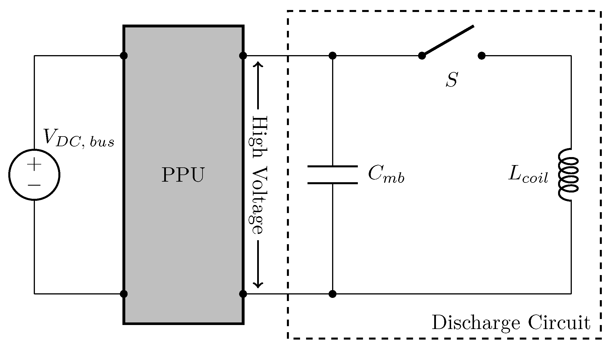
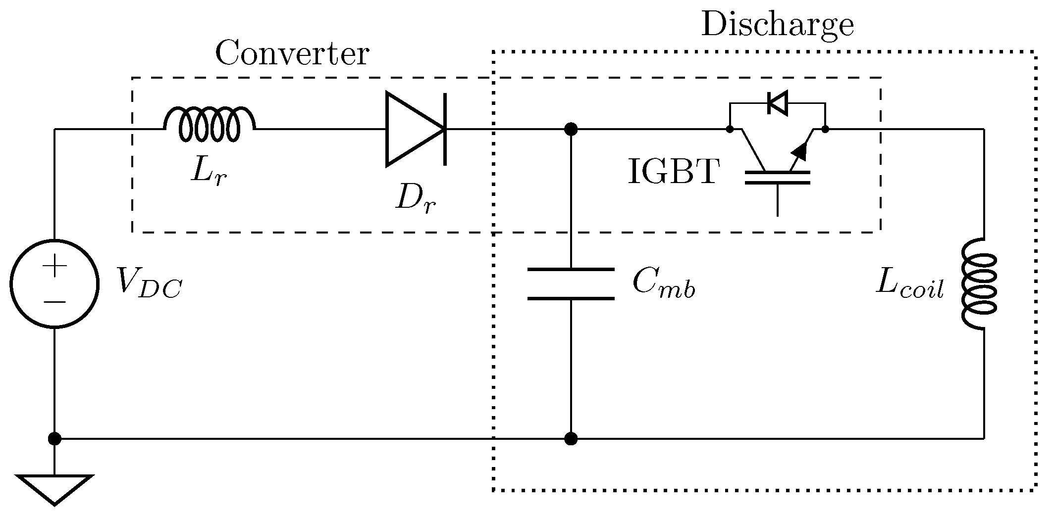
An inductive pulsed plasma thruster (IPPT) is a spacecraft propulsion system that uses short, high current electrical pulses flowing through an inductive coil or set of coils to drive currents in a plasma and expel it at high speed. While there are multiple implementations that can operate in the manner described, they all share some common features. The electrical energy is typically stored at high voltage in capacitors before being discharged rapidly through the inductive coil. Switches for the pulsed circuit are required to hold off voltages of multiple kV during the capacitor charging phase and then often conduct 10 s of kA of current when discharging. The switches must allow for a very high current rise rate during pulses that last on the order of 1–10 s. Coupling between the coils and the propellant is all accomplished inductively, making these devices electrodeless. This electrodeless nature eliminates electrode erosion caused by high-rate charge transfer across the material-vacuum interface found in thrusters with electrodes, where the propellant is in contact with electrodes and completes the electrical circuit. As such, IPPTs are capable of operation on propellants that could be corrosive to electrodes in other plasma thrusters.
While the thruster types described in this paper have unique aspects to their operation, at a high level IPPTs operate through a combination of Ampère’s and Faraday’s laws, given respectively as:
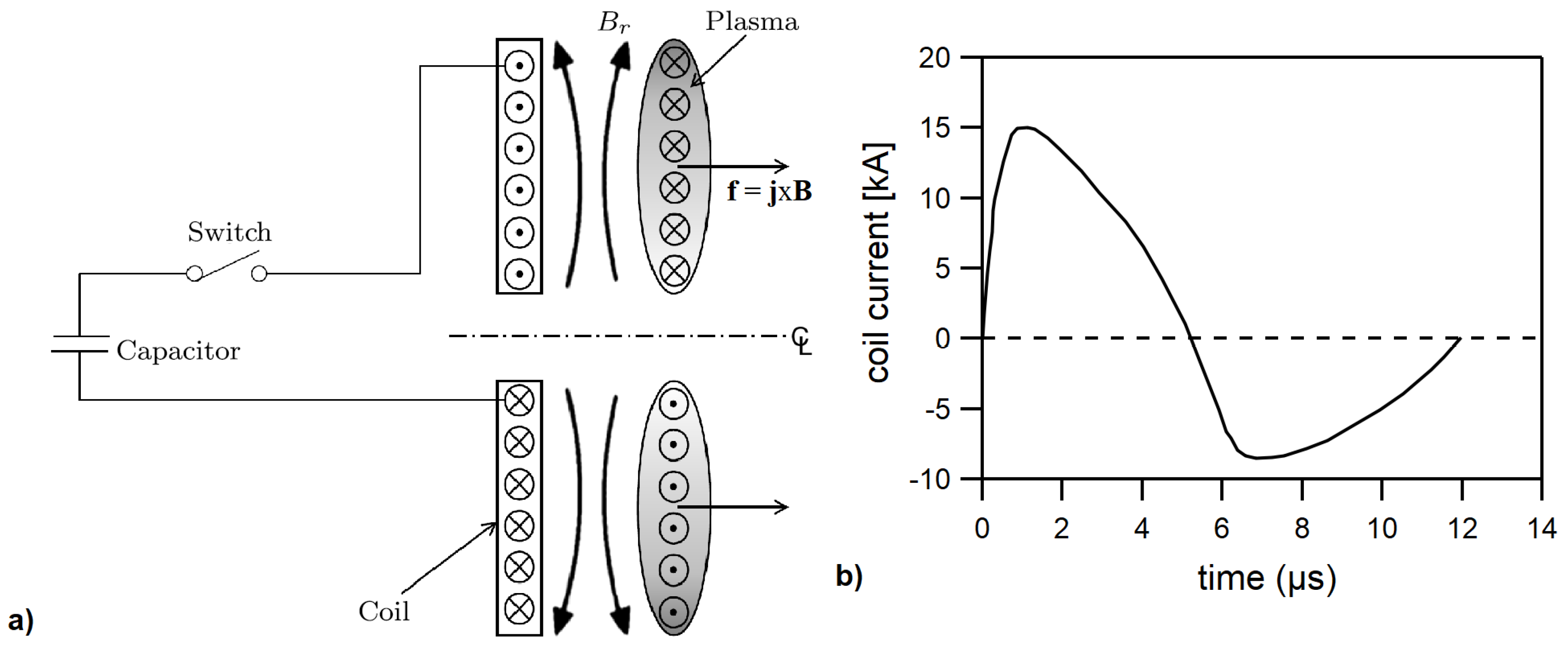
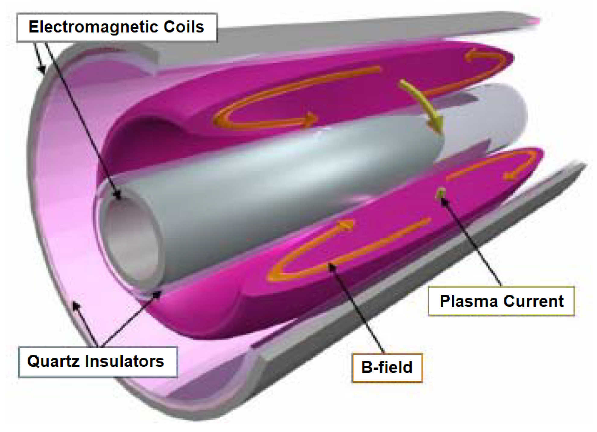
In these equations the electric and magnetic field vectors are and , the current density vector is , and the permeability of free space is . Using the schematic of Figure 1a for illustrative purposes, current flowing azimuthally in the coil produces a radial magnetic field through the relationship in Ampère’s law. A fast time-variation in the current produces an equally rapidly varying magnetic field that, through Faraday’s law, induces a strong azimuthal electric field. The direction of the electric field is opposite to the current in the coil, giving rise to a counter-rotating azimuthal plasma current. The currents in the coil and plasma electromagnetically repel each other, axially accelerating the current-carrying plasma to yield thrust.
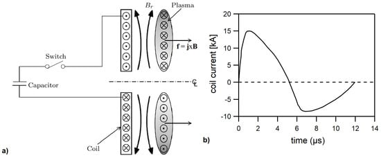
Figure 1.
(a) Schematic showing the basic operation of a planar IPPT, where the Lorentz body force in the axial direction arises from the interaction between the azimuthal plasma current density and the radial magnetic field . (b) Sample discharge current from the PIT MK Va for one of the nine parallel coils (from [9]).
IPPTs must overcome inherent difficulties related to both ionization and acceleration to achieve high efficiencies [1]. Since the primary (external) circuit is completed without the presence of an induced (secondary circuit) plasma current, a delay between current initiation in the primary circuit and ionization of the gas will result in increased resistive energy dissipation in the primary circuit. In addition, once the secondary plasma current exists, electrodynamic coupling between the two current loops is a function of the mutual inductance between the two circuits, which decreases quickly as the separation between the plasma and the external circuit increases. Efficient operation can only be achieved if a significant fraction of energy transfer to the secondary circuit can be accomplished rapidly, before the plasma is too distant to effectively couple with the primary circuit. Finally, in addition to transferring energy to the plasma quickly, an efficient pulse circuit must be capable of performing significant electromagnetic work on the propellant. The inductance of the circuit increases as a function of time, and this increase is representative of the amount of electromagnetic work the circuit is capable of performing. For efficient acceleration the ratio of the coil inductance , which is the amount by which the circuit inductance increases during the pulse, to the initial (also called stray or parasitic) inductance , which is fixed and performs no electromagnetic work on the propellant, must be much larger than unity [2].
For the purposes of classification, we subdivide IPPTs into two general categories. Inherent in these categories is the nature of the magnetic flux surfaces in the thruster. One category consists of thrusters in which a current sheet is formed and accelerated in the direction perpendicular to the electromagnetic coil. These thrusters are characterized by open magnetic flux surfaces in the gap between the coil and the plasma current loops, with the flux surfaces exiting the gap at the extents of the coil and current sheet. The main thruster of this type in the literature is the Pulsed Inductive Thruster (PIT) [3], though theta-pinch and conical theta-pinch devices can also be operated in this mode [4]. The other category is comprised of thrusters in which closed magnetic flux surfaces are embedded within and aid in confinement of the plasma. Plasmas in this configuration are generally known as compact toroids, with those under development for spacecraft propulsion known as field-reversed configuration (FRC) thrusters [5] or plasmoid thrusters [6].
It is a goal of the present paper to provide a review of the state-of-the-art for all IPPT research and development. There is a comprehensive review of the open magnetic flux surface planar thrusters [7] and a review of FRC plasma devices as they relate to fusion [8], but to the authors’ knowledge there has never before been a single publication that presented a technological review of all open and closed magnetic flux surface IPPT types. We discuss the major thruster variants, describing their modes of operation and presenting any available experimental measurements that aid in quantifying propulsive performance. The modeling techniques that have been applied to IPPTs are also reviewed, with emphasis placed on the insights that have been gained by these efforts. Finally, we discuss the major subsystems needed to operate an IPPT, describing the current state-of-the-art and present limitations of these subsystems and their constituent components.
The other purpose of this paper is to describe possible paths to advance IPPTs beyond the current state-of-the-art. Included in this description is a listing of the present gaps in technological capabilities or basic understanding of physical processes in these thrusters or their constituent subsystems. Following the same structure as the review of the present state-of-the-art, we provide a discussion of various potential means to improve different thruster variant designs by enhancements to current modeling capabilities and through advancement in the capabilities of specific subsystems and components.
2. Review of Inductive Pulsed Plasma Thrusters
We proceed with a description of the different IPPT variants and their inherent properties and operating characteristics. The results of key test campaigns are summarized and, when available, the measured performance for each thruster variant is presented. The specific impulse (thrust per unit weight flow of propellant) in any pulsed thruster is:
where is the average exhaust velocity of all the propellant injected into the thruster for a pulse, is Earth’s gravitational acceleration constant, is the impulse bit or impulse per pulse of the thruster, and is the mass bit or injected propellant mass per pulse. Likewise, the thrust efficiency in a pulsed thruster is the ratio of directed kinetic energy in the expelled plasma jet to the initial stored electrical energy , and is given as:
2.1. Open Magnetic Flux Thrusters
Open magnetic flux IPPTs have an inductive coil configured such that when a capacitor bank is discharged by closing a switch, an azimuthal current is driven in the coil. If there is an ionized gas over the face of the coil, the time-varying current in the coil will induce a counter-rotating azimuthal current sheet in the plasma that mirrors the geometry of the driving coil, as illustrated in Figure 1a for a planar thruster variant. The coil and plasma currents produce a concentrated axisymmetric magnetic field in the r-z plane that is sandwiched between the two current rings. The plasma is accelerated to high exhaust velocities in the direction perpendicular to the coil face by the Lorentz body force arising from the interactions of the plasma current and magnetic field. Any gas that is encountered by the accelerating current sheet may be entrained in the sheet. The representative discharge current waveform in Figure 1b shows the relative timescale and magnitude of the current in an IPPT.
2.1.1. Planar Thrusters
The IPPT variant that has seen the most sustained development work as a propulsion system is the planar thruster known as the Pulsed Inductive Thruster (PIT), researched by Dailey and Lovberg [3]. This thruster type has been the subject of many past experimental studies and was discussed in detail in a comprehensive review by Polzin [7]. What follows is a summary of the major experimental results described in that review, as these results represent the current state-of-the-art for planar IPPTs.
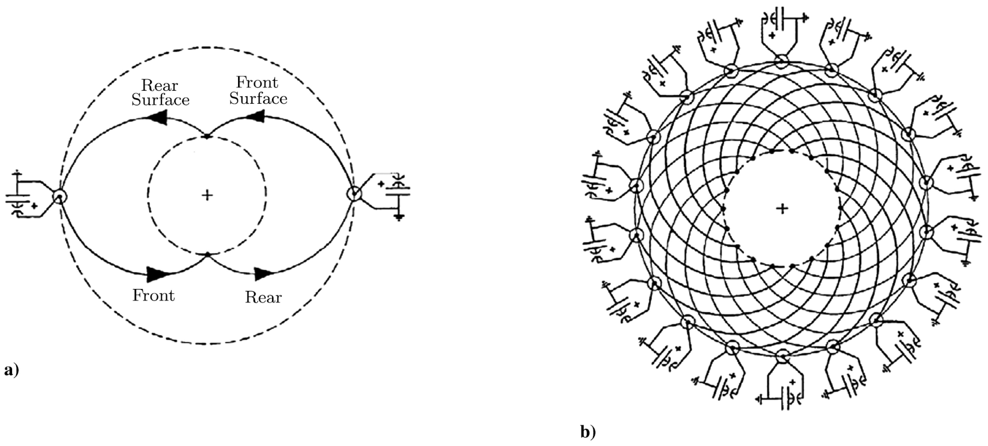
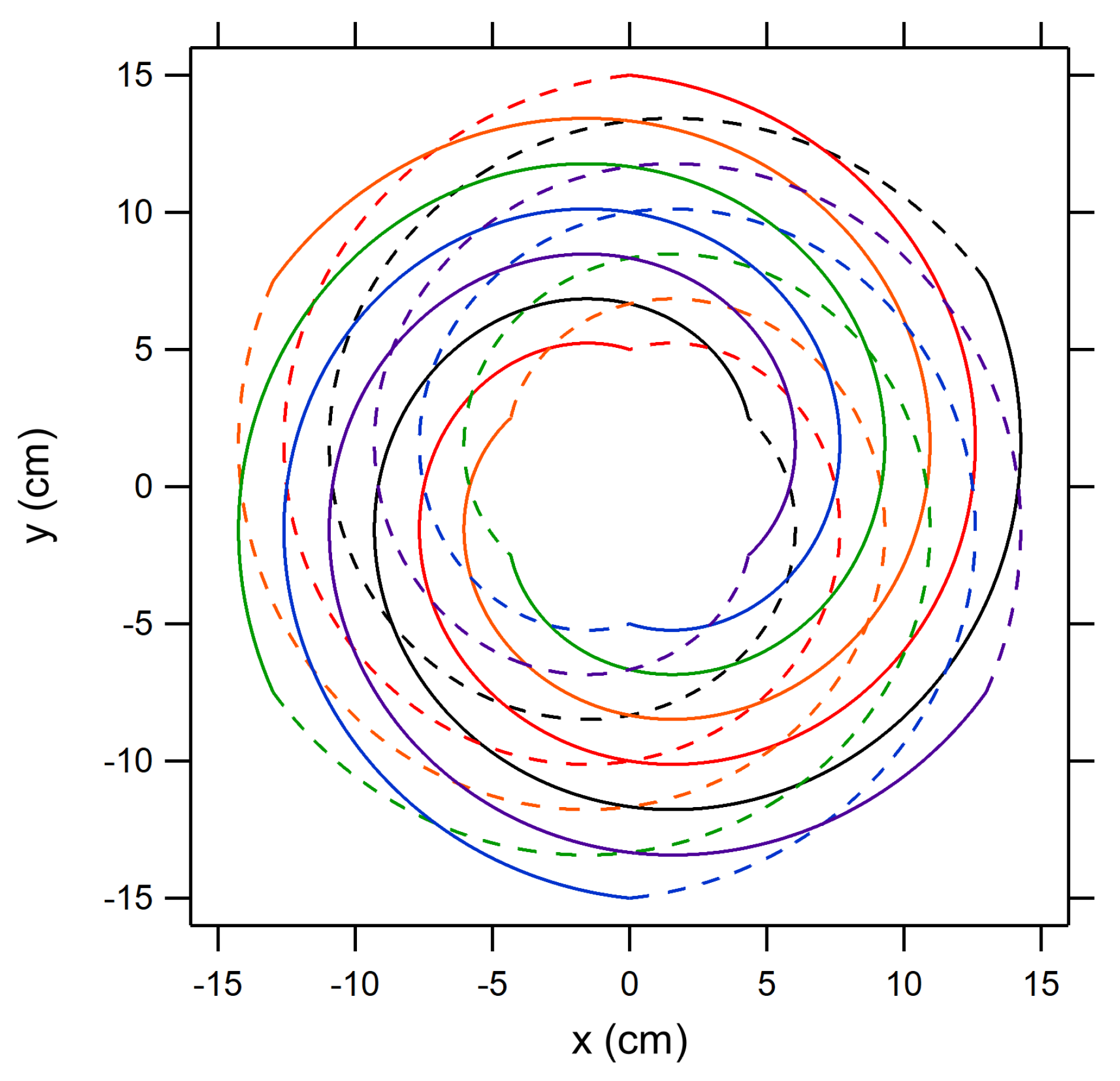
Significant work on the PIT was aimed at minimizing the delay time between the initiation of the external current pulse and the breakdown of the gas over the face of the coil. This was accomplished by increasing the current rise rate in the coil, as this generates stronger fields in the gas and serves to more rapidly ionize the propellant. The current rise rate can be raised by increasing the initial charge voltage on the capacitor bank or by decreasing the parasitic or stray inductance in the circuit. Many tests over a number of years were conducted in the 15–24 kV range. However, the biggest improvement was realized in the PIT MK V and MK Va where the coil was reconfigured from a number of parallel Archimedes spirals connected to a single capacitor bank to the Marx-bank configuration shown in Figure 2 [3]. In this configuration, the azimuthal voltage initially applied to the coil is double that of any individual capacitor, so the nominal 15–16 kV of capacitor charge appears as a net 30–32 kV initial azimuthal voltage. The Marx-bank configuration also has the advantage of adding the stray inductance for each leg of the circuit in parallel, yielding a much lower net stray inductance for an overall lumped-element circuit. The combination of greater net azimuthal voltage and lower stray inductance resulted in a much greater current rise rate in the thruster, reducing the delay in the breakdown of the propellant and also producing a far more uniform current sheet over the coil face [7].
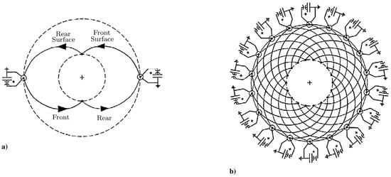
Figure 2.
PIT MK V and MK Va Marx-generator coil configuration: (a) one complete Marx-generator loop and (b) the nine complete loops comprising the entire coil (from [3]).
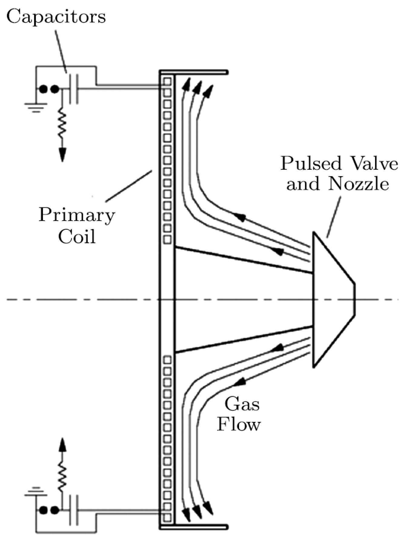
The injection of gas in the PIT is also a major issue that was addressed over a number of experimental campaigns. The primary problem is that injected gas can readily escape to the vacuum of space before it has been electromagnetically accelerated. This escaping gas moves slowly compared to the portion of the gas that is electromagnetically accelerated, reducing the average of the injected gas. To address this issue, a tall conical structure was located along the centerline of the thruster with nozzles that injected gas towards the thruster face as depicted in Figure 3. It was shown that the gas stagnated and had to first spread radially along the coil face before it could escape to vacuum, yielding a somewhat uniform propellant distribution over the coil [3,10]. After the gas had moved radially outward but before too much had the opportunity to escape, the current pulse was initiated, ionizing and accelerating the gas.
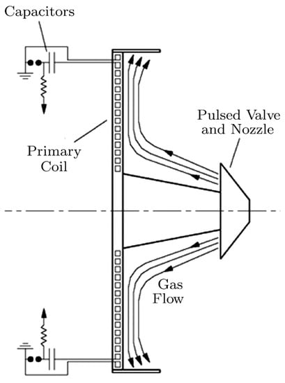
Figure 3.
Schematic showing a typical propellant injection scheme employed on the PIT (from [3]).
Initial work on the PIT involved coils with outer diameters of 20 and 30 cm [11,12], but most later iterations had coil diameters of 1 m [3,13,14]. The distance over which the coil electromagnetically interacts or couples with the gas is, to first order, a fixed fraction of the overall coil diameter. Consequently, increasing the coil diameter increases the overall interaction distance. All other things being equal, increasing the interaction distance will increase the overall amount of injected gas that is within the coupling region when the thruster circuit is discharged. The nature of the reduction in the electromagnetic interaction as a function of distance is such that the closer the gas is to the coil, as a fraction of the overall interaction distance, the greater the potential electromagnetic interaction.
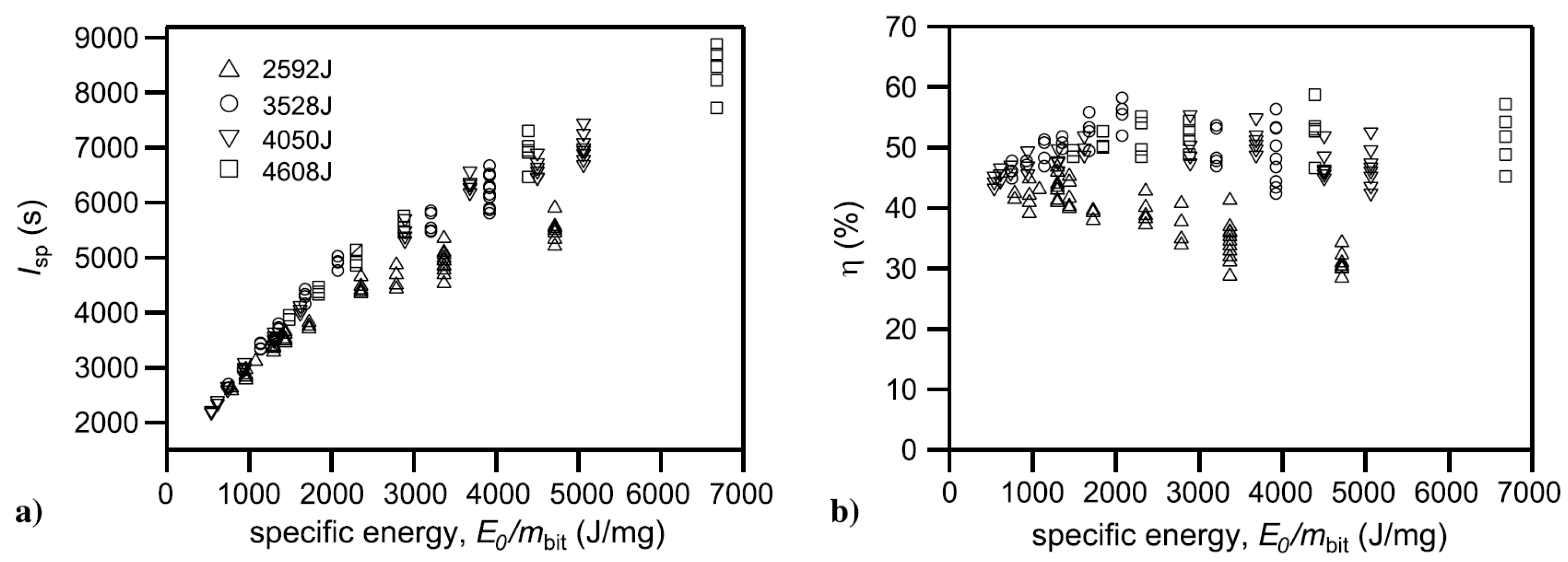
The PIT MK V (4.5 F bank capacitance) and MK Va (9 F bank capacitance)—both configurations are sometimes collectively referred to in the literature as the MK V—represent the current IPPT state-of-the-art in terms of thruster performance. Of all IPPTs, there are more direct thrust measurements for these variants than for all other thruster concepts in the literature [7]. These thrusters have published thrust measurements for single-pulse operation on a number of different propellants, specifically helium (He), carbon dioxide (CO), argon (Ar), ammonia (NH), and simulated hydrazine (N + 4NH). Of all these propellants, the highest performance was achieved on ammonia, with efficiencies of over 50% in the MK Va [3] as illustrated in Figure 4. Notably, this high efficiency was demonstrated over a broad range of , which is very interesting from a mission planning perspective because it shows a range over which the can be throttled without a significant reduction in performance. In the same way that any electric motor exhibits a peak in efficiency as a function of motor speed, this constant high efficiency regime was understood as operation in the regime where there is a match between the external circuit and gas acceleration timescales such that the transfer of electrical energy into kinetic energy of the plasma is maximized. Finally, it was shown that the efficiency was reduced and the did not rise as quickly as a function of increasing specific energy () when the discharge energy per pulse was ∼2600 J. This observed trend is presently not well understood.
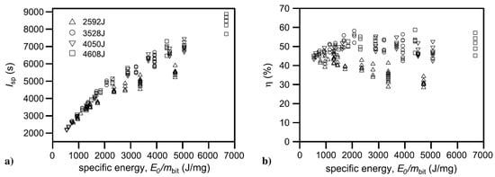
Figure 4.
(a) Specific impulse and (b) thrust efficiency as a function of specific energy for the PIT MK Va thruster operating on ammonia propellant (data from [3]).
There were attempts to use preionization to increase the primary discharge ionization rate in planar IPPTs, though the results of such experiments were decidedly mixed. In the 30 cm planar IPPT a low energy fast current pulse was driven through the acceleration coil prior to the main discharge [12]. This did preionize the gas, but the fields produced by the current in the coil have the same orientation as those that accelerate the propellant, resulting in the preionized gas being electromagnetically pushed a finite distance away from the coil face before the main discharge pulse. Energy coupled into the propellant at the location of the now-displaced preionized gas, but as this location was further from the coil, there was less potential for electromagnetic work.
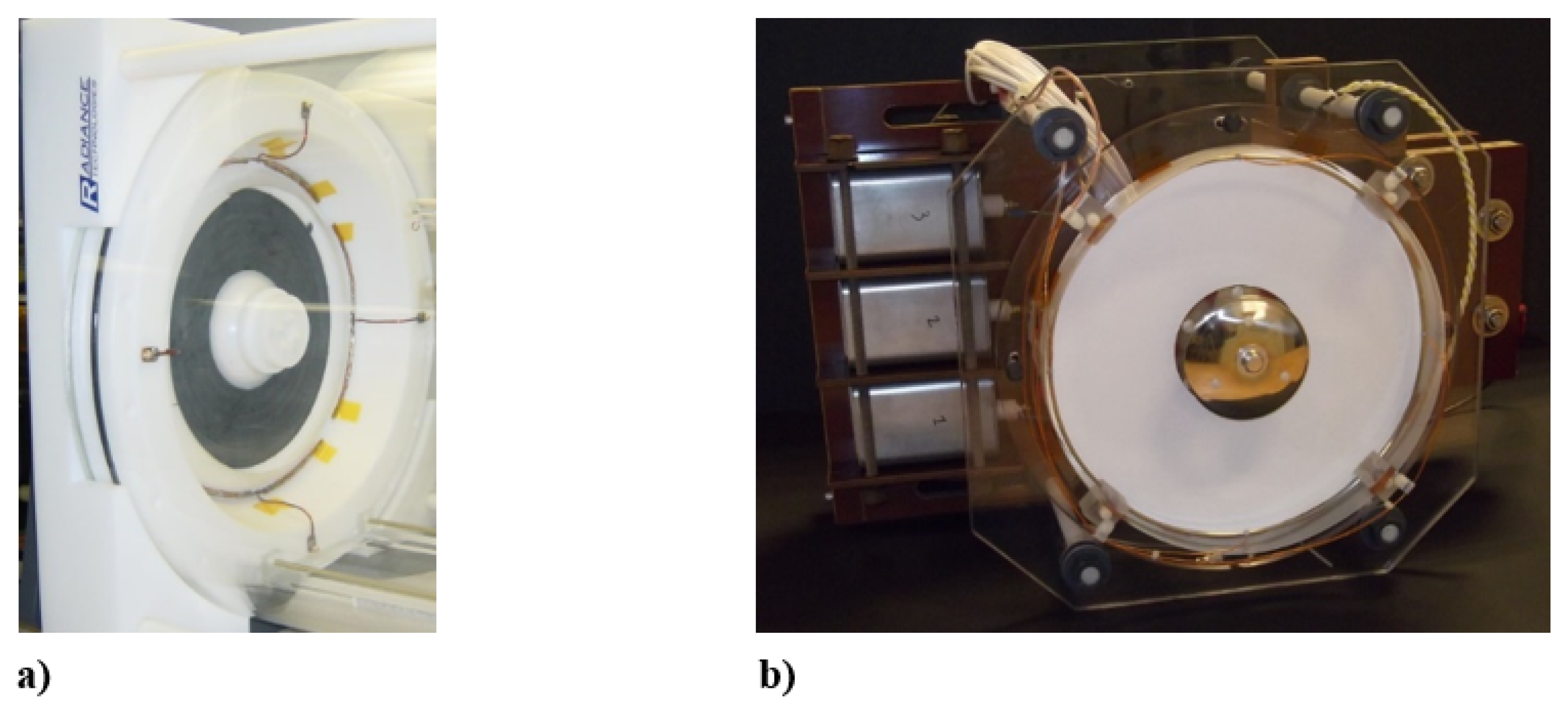
In the Faraday accelerator with radio-frequency assisted discharge (FARAD) device a planar coil was used in conjunction with a gas that was ionized in an RF discharge and directed to the coil face by an applied radial magnetic field [15,16]. The discharge energy was much lower in FARAD compared to the PIT (<100 J compared to 4 kJ), so the plasma current would not form without the presence of the preionization. Testing of the initial FARAD proof-of-concept device demonstrated that preionization could be used to lower the main discharge requirements on propellant breakdown, but further study is required to more properly quantify this effect. In a later higher-energy 100 J/pulse implementation of the FARAD concept, shown in Figure 5a, a pulsed RF vector inversion generator (VIG) discharge [17] preionization scheme was employed. In this thruster at the discharge energy levels tested, the main discharge was sufficient to ionize the neutral gas without preionization and no attempt was made to more thoroughly quantify the effects of preionization on reducing the breakdown voltage or improving thruster performance.
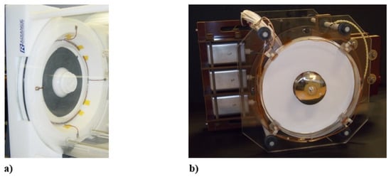
Figure 5.
(a) The FARAD thruster (from [17]), (b) The 27 cm diameter planar IPPT (from [18]).
The NASA-Marshall 27 cm diameter planar IPPT, shown in Figure 5b, was assembled to test cyclic operation with all the major subsystems of an IPPT, including a solid-state switching system, a pulsed gas valve, and preionization [18]. The thruster was designed to operate at cyclic rates up to 30 Hz and average powers in the range of 1–5 kW. The acceleration coil consisted of six two-turn spiral-wound leads in parallel, driven by a 10 F capacitor. The switch used was a hockey-puck type thyristor rated for a maximum hold-off voltage of 4.5 kV, a peak current of 30 kA, and a maximum of 22 kA/s. A fast pulsed gas valve, with an opening time of 300 s, was used to inject propellant gas (argon) over the coil face. The device had a DC glow discharge preionizer. As with FARAD, the main bank discharge was able to ionize the gas by itself, and there was no systematic study of the effect of the preionizer. The thruster was tested in vacuum, however to-date there have been no thrust measurements on the device.
2.1.2. Conical Theta-Pinch Thrusters
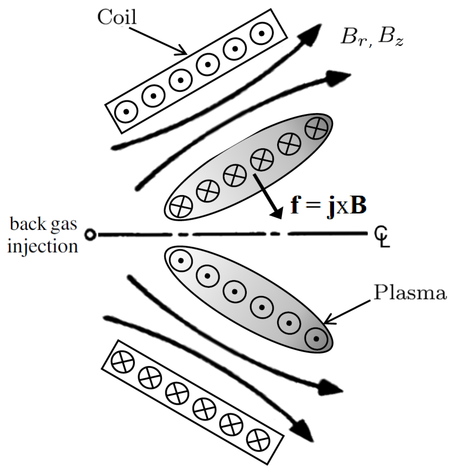
In a conical theta-pinch (CTP) IPPT operating in the open magnetic flux mode, a current sheet forms on the interior surface of a conical coil and is accelerated in both the axial direction and radially-inward as illustrated in Figure 6. There has been significantly less research performed on open magnetic flux CTP devices relative to the planar IPPTs. It was hypothesized that the CTP geometry may have an advantage over planar thrusters because the propellant would be better contained within the volume defined by the conical coil. This geometry was not without potential issues, however. Specifically, since the accelerating force is in the direction perpendicular to the coil face, radially-inward motion will be imparted to the gas that must be converted by some means to axial motion if it is to produce thrust.
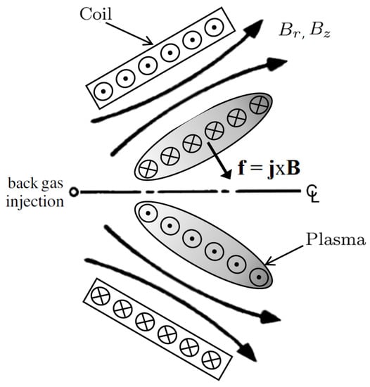
Figure 6.
Schematic showing the basic operation of an open magnetic flux conical theta-pinch inductive pulsed plasma thruster. The Lorentz body force , with components in the radial axial directions, arises from the interaction between the azimuthal plasma current density and the radial and axial magnetic field components .
Hallock et al. [4,19] performed testing on CTP-IPPTs proof-of-concept devices fabricated with cone angles of 20°, 38°, and 60°, measured from the centerline of the thruster. The exit diameters for these three coils were approximately 15, 23, and 25 cm, respectively. Tests were conducted in both the single pulse mode and at repetition rates up to 5 Hz and discharge energies up to 500 J/pulse. While other pulsed thrusters have operated at much faster pulse rates and greater average power throughput, their discharge energies per pulse were more than two orders of magnitude lower than the CTP testing. Also, like the PIT series of thrusters, the performance was directly measured on a thrust stand for single pulse and repetition rate operation.
Two different gas injection schemes were employed in the CTP testing. In the first scheme, gas was injected from the back of the thruster at the location illustrated in Figure 6 labeled ‘back gas injection’. This resulted in exceptionally low impulse bit measurements, implying that only a small amount of the injected gas was reaching the coil face while most of the gas remained nearer to the centerline and too far from the coil to be effectively accelerated. To test that hypothesis, a scheme was implemented to inject gas directly against the coil with a swirl imparted to the propellant to hold it against the face longer. This appeared to partially remedy the problem as the impulse bit of the thruster did indeed increase by almost a factor of 4–5 relative to when gas was injected from the back of the thruster [19].
Even when the gas was injected against the coil face, the efficiencies based on thrust measurements were below 6% on argon [4]. These data compare unfavorably with the ∼15–30% efficiencies measured with argon in the PIT MK I and MK V planar thrusters [7]. Interestingly, the impulse bits and efficiencies were greatest for the 38° cone angle, with markedly lower values measured for the 20° and 60° cone angles. One conclusion from the experimental data was that the radial velocity imparted to the gas was simply not being effectively converted to axial motion, which can result in significant efficiency losses. However, that would imply that the largest cone angle should have the best performance, which was not the case. It was noted that the smaller, lower power planar IPPTs were less efficient than larger, higher power PITs. The results of that work point to additional loss mechanisms in the CTP-IPPTs tested, specifically incomplete current sheet formation and excessive dissipation of energy in the entrainment of gas encountered farther from the the coil face where the electromagnetic acceleration force is reduced.
Preionization techniques were tested in the CTP geometry [19]. Application of a DC voltage to ionize the gas before the pulse was implemented, and for gas injection from the back of the thruster this preionization was necessary in ionizing the gas over the coil face during the main discharge. It was found for the discharge energies tested that when the gas was injected directly against the coil preionization was not required and, in fact, had no observable effect on the discharge current waveform or the measured performance. Consequently, it was not employed for the CTP performance measurements previously discussed. A second technique used a microwave-driven electron cyclotron resonance (ECR) discharge where permanent magnets oriented along the outside of the coil would form regions of cyclotron resonance along the inner face of the acceleration coil. While this technique succeeded in producing a luminescent plasma at microwave power levels up to 3 kW, it was discarded because it presented logistical challenges in terms of transferring the power onto the thrust stand. In addition, the high frequency waves were driving currents in the thruster coils that were causing damage to the thruster and insulation.
2.2. Closed Magnetic Flux Thrusters
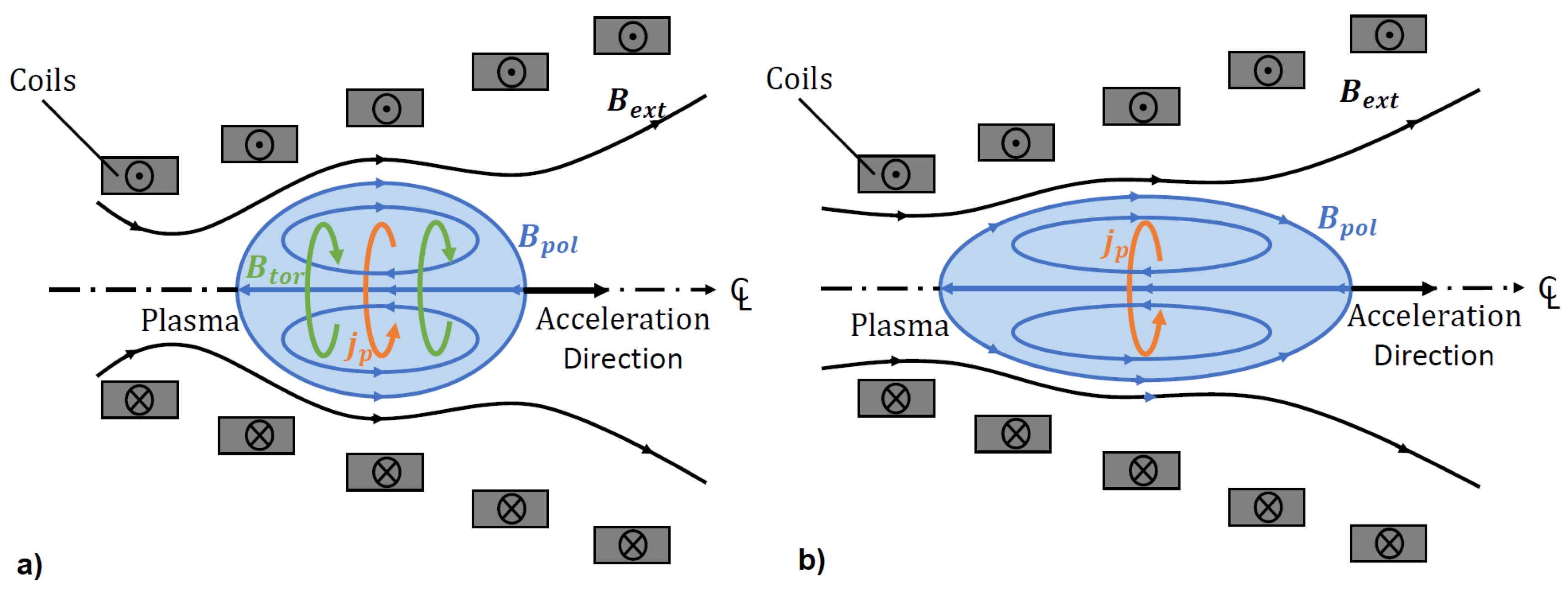
Closed magnetic flux IPPTs are similar to open magnetic flux IPPTs from a circuit standpoint: on closing a switch, energy stored in a capacitor is discharged as current through an inductive coil. Under certain circumstances the current induced in the ionized propellant gas can produce a closed internal magnetic field topology. Plasmas embedded within such a closed magnetic field structure are referred to as plasmoids or compact toroids. The closed magnetic flux isolates the plasmoid from its surroundings and enables both passive (thermal) and active (electromagnetic) acceleration. Compact toroids fall into two broad categories: spheromaks, which have both poloidal and toroidal magnetic fields, and field-reversed configurations (FRC), which have poloidal fields only [8]. Each of these categories is illustrated schematically in Figure 7.
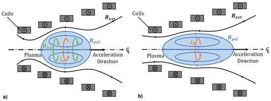
Figure 7.
Schematic illustrations of conical coil sets containing (a) a spheromak plasma and (b) a field-reversed configuration (FRC) plasma, showing the directional sense of the current in the coils, the azimuthal plasma current , and poloidal magnetic field , the magnetic field external to the plasma , and the toroidal magnetic field in the spheromak configuration.
Closed magnetic flux IPPT research has mainly focused on the formation and acceleration of FRCs [20]. The FRC plasma is characterized by an azimuthal current density and no azimuthal magnetic field. The magnetic field vector instead lies primarily in the meridional (r-z) plane. A high plasma beta, wherein the thermal energy density of the plasma is comparable to the magnetic energy density, is required to achieve the closed flux configuration. We note here that the plasma beta (typically defined as the ratio of the plasma pressure to the external magnetic pressure) is a local quantity and is not necessarily all that useful when discussing these types of thrusters. In fact, this value can exhibit a wide variation within the plasma and greatly exceed unity at certain points (at the O-point of an FRC, where the magnetic field vanishes, beta approaches infinity). When discussing beta in an FRC context, what is often meant is the volume-averaged beta () [8,21,22]. This term is derived based on an axial balance of the tension of the field line and the plasma pressure in the FRC. The derivation of assumes a prolate, axisymmetric FRC inside a cylindrical coil that is “sufficiently” long such that the field lines are straight at the mid-plane and at the ends of the coil. A result of this analysis is
where and are the separatrix and coil radii respectively. Typically, the ratio of radii is approximately equal to 0.5, which makes roughly equal to unity. An FRC that extended to radially fill the volume inside the coil would only have a minimum of 0.5 (i.e., 0.5 is the lower theoretical limit of in these devices), so in practice, 0.5≤<1.0, with some fusion FRC experiments achieving of ∼0.9 [23].
The ability to achieve a high motivated intense FRC plasma research for compact fusion energy reactor applications. The fusion energy research community pioneered the idea of inductively accelerating two FRC plasmas to high velocities (∼100 km/s) and colliding them to produce a single plasmoid within a confinement chamber [24,25]. In this case, the main motivations for accelerating FRCs were to provide kinetic stability during formation and repurpose plasma kinetic energy for heating and compression during confinement. While we do not wish to provide an in depth discussion of instabilities here (the discussion of FRC stability being the subject of numerous papers), we note that what was long considered to be the most dangerous instability was the m = 1/n = 1 internal tilt mode [23,26], which is not driven by . In most cases, the 1–10 s timescales for plasma thruster applications is too short for instabilities to greatly impact the plasma before it is expelled.
FRC plasmas can be formed through a variety of different processes. In this section we will classify concepts according to their formation method and review different test articles that have applied these techniques to develop accelerators for in-space propulsion.
2.2.1. Field-Reversed Theta-Pinch FRCs
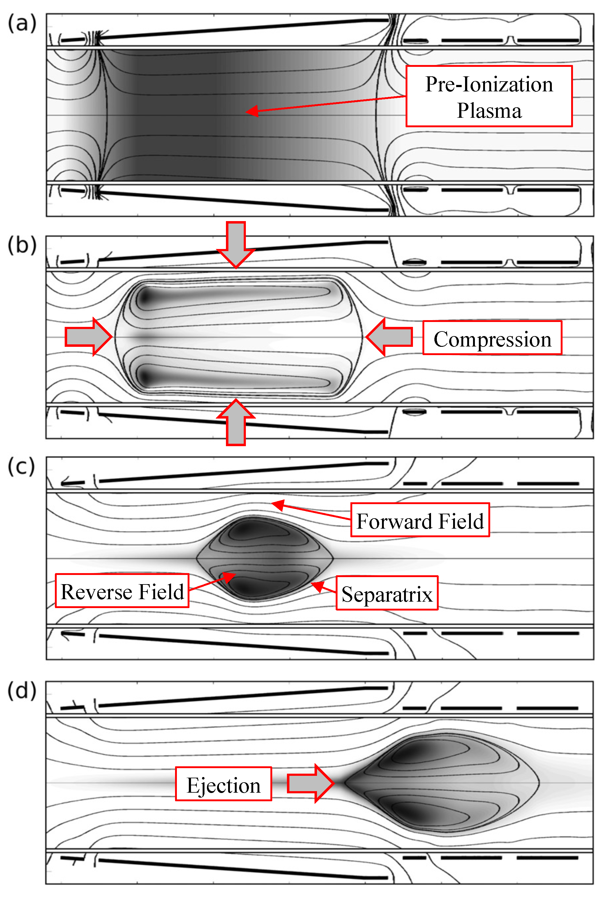
The first FRCs were created using a method referred to as field-reversed theta-pinch (FRTP) formation [27]. FRTP formation (illustrated in Figure 8) begins with a background applied axial magnetic field embedded within a partially ionized plasma (often referred to as the preionization plasma). A strong pulse of current is generated in a coil or coils placed on the outside of the plasma chamber and aligned concentric with the plasma. The coils are designed to create a magnetic field (forward field) that opposes the magnetic field initially embedded in the plasma (reverse field). If the current rise time is faster than the inductive decay time of the plasma, the reverse field is unable to diffuse from the plasma and a closed magnetic flux topology is formed. A well-defined flux surface (separatrix) separates the reverse and forward fields, and provides stability to the plasma during acceleration and translation [28]. Radial compression of the FRC increases the magnetic field strength, which simultaneously increases the field-line tension and causes the FRC to contract axially. Radial and axial compression of the plasma occurs during this process prior to reaching an equilibrium state wherein the external magnetic pressure is balanced by the plasma pressure. Controlling magnetic field reconnection through programmed formation of the FRC proved to be crucial in creating stable, long-lived FRC plasmas [8]. For IPPT applications using conical theta-pinch geometries, research suggests it is possible to achieve this closed-flux equilibrium state on timescales faster than the ejection time of the plasmoid [29]. However, uncertainties exist regarding the scalability of FRTP to energy levels useful for electric propulsion, the sensitivity to preionization, the recovery of thermal energy obtained during compression, and the quantification of potentially significant plasma-wall interactions during field-reversal.
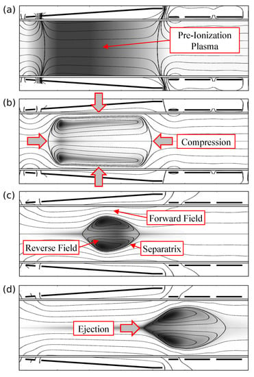
Figure 8.
Schematic showing field-reversed theta pinch formation for closed magnetic flux thrusters: (a) preionization plasma is introduced into a background magnetic field; (b) a strong pulse of current generates a time-dependent magnetic field with polarity opposing the initial background magnetic field that compresses the plasma both radially and axially; (c) a closed magnetic field structure confines the plasma within a separatrix that divides the forward and reverse fields; and (d) magnetic field gradients in the axial direction accelerate and eject the resulting plasmoid (Reproduced/modified from [29]; with the permission of AIP Publishing.).
The Plasmoid Thruster Experiment (PTX) [6,30,31] used a conical theta-pinch coil to both form and accelerate plasmoids. The primary acceleration mechanism is the Lorentz body force caused by the interaction of the azimuthal plasma current and the applied field generated by the coil. Some acceleration may also be due to the conversion of thermal energy to directed kinetic energy when the plasma expands in the magnetic nozzle formed by the coil, however this contribution has to-date not been quantified. In PTX, plasmoids were formed by discharging a capacitor charged to 35 kV (energy of ∼350 J) through a single-turn conical theta-pinch coil with a 17.5° half-angle. The resulting discharge had a peak current of 50 kA with a ringing frequency of 500 kHz. The plasma was formed in a Pyrex tube connected to the rest of the vacuum chamber while the coil was located outside the vessel. PTX used the first/second half-cycle formation technique first used in FRTPs [8]. In the first half-cycle the plasma is formed (pre-ionized) and seeded with the reversed (bias) field. The subsequent half-cycle applies the forward field causing the magnetic field lines to reconnect into a closed field-line structure. A separate Blumlein preionizer (frequency of ∼4.5 MHz) was attached to the coil, but only used a few times before it failed due to an interaction with the main bank. Propellant gas was injected using a fast pulsed gas valve (PGV) with a plenum isolated from the gas supply by a limiting orifice. Owing to the characteristics of the circuit and the switch (in this case, a Perkin-Elmer GP-32B spark-gap) PTX could only be operated over a narrow range in voltage; in practice it was almost always set to 35 kV. Experimental conditions were varied by changing the gas pressure in the plenum and the delay time between the valve opening and the capacitor discharge.
A wide array of diagnostics was used with PTX. A three-channel excluded flux-array under the theta-pinch coil (later expanded to six channels) was used to determine the location and shape of the separatrix. Quadruple Langmuir probe measurements were performed to determine the evolution of the electron temperature, plasma density, and ion Mach number. Line integrated plasma density was measured with a quadrature heterodyne HeNe interferometer, similar to the system used in Refs. [32,33,34]. Additional measurements were performed using internal magnetic field probes, a 0.3 m spectrometer, and a 100 Mframe/s framing camera. End-on imaging of the coil showed that the preionization occurred during the second half-cycle (after the first zero-crossing in current) [6]. The interferometry data show that, for long valve delay times, the plasma pushes and accelerates neutral gas ahead of the plasmoid [31]. Electron temperatures measured downstream with the quadruple Langmuir probe were up to 20 eV for hydrogen and lower than that (∼8 eV) for argon [30], although there were indications that the temperatures were much higher closer to the coil. Magnetic probe data exhibited a double-peak structure suggesting the formation of two distinct plasmoids—a hypothesis that was consistent with the high-speed imaging. Optical velocimety measurements indicated argon velocities of ∼22–28 km/s, providing order of magnitude agreement with the quadruple Langmuir probe measurements. Excluded flux array measurements indicated that a closed field-line plasmoid was created with argon but not with hydrogen [35]. No evidence of closed flux surfaces was observed downstream of the coil. It was surmised that with hydrogen, the plasma was rapidly expelled out of the coil before reconnection could occur.
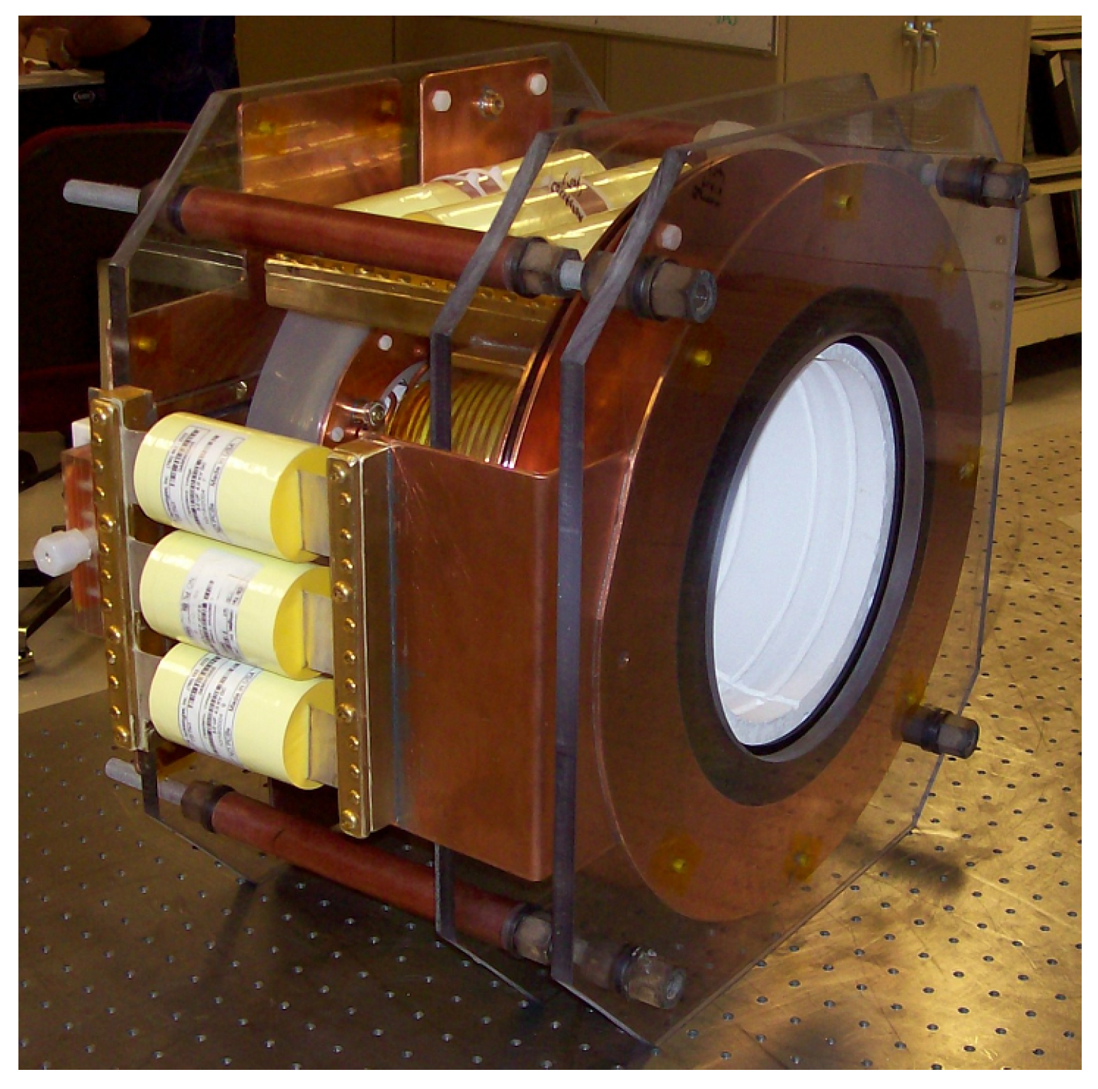
The PT-1 plasmoid thruster shown in Figure 9 was fabricated as a brass-board device based on experience derived from PTX [36]. It had separate drive and bias coils, each consisting of four parallel three-turn leads wound on an alumina form, and each driven by its own capacitor bank. In series with the bias coil, fore and aft of it, were two reverse-wound field-shaping coils. The purpose of these were to create a cusp-field on either end of the coil to promote faster and better controlled reconnection. PT-1 could be operated in two modes: a plasmoid thruster mode with the bias coil driven in the opposite sense to the drive coil, or a conical theta-pinch mode with the bias and drive coils driven in the same sense. Both drive and bias circuits were switched with spark-gap switches, later replaced with thryristors. Glow discharge and VIG preionizers were attempted, but owing to programmatic considerations, no extensive testing was done with PT-1.
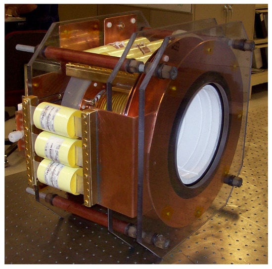
Figure 9.
The PT-1 plasmoid thruster test article.
The Magnetically Accelerated Plasmoid (MAP) experiment [37] also employed a conical theta-pinch coil to form and accelerate FRC plasmoids. In addition to the main theta-pinch coil, MAP possessed a series of downstream magnetic coils that were sequentially pulsed to provide additional acceleration by establishing a traveling magnetic wave that could electromagnetically push the plasmoid. Experiments successfully demonstrated the power supply and switching technologies required to form the magnetic wave. Preliminary results on a deuterium-helium gas mixture measured plasmoid velocities up to ∼180 km/s. By combining density measurements from a HeNe interferometer with FRC equilibrium measurements from magnetic probes, the MAP experiments were the first to provide a technique for estimating the mass contained within the plasmoid.
The Missouri Plasmoid Experiment (MPX) [38,39] was designed to study the physics of FRTP plasma formation with heavy gases when operating at discharge energy levels of relevance to electric propulsion. Experiments focused primarily on the preionization phase of FRC formation. Early results demonstrated a strong dependence of preionization energy efficiency on gas pressure for both air and argon over a pressure range from 0 to 60 mtorr [38]. Argon demonstrated greater shot-to-shot repeatability and higher energy transfer efficiency at lower pressures, where the energy transfer efficiency was defined as the energy absorbed into the plasma as a fraction of total pulse energy. The maximum energy transfer efficiency for argon was measured to be 25% and occured nearly 10 s (roughly four discharge periods) after pulse initiation. Notably, it was not determined how energy transferred from the coil was distributed among various plasma energy channels such as ionization, heating, and acceleration. Application of a low-power DC plasma discharge during preionization was later found to improve energy transfer at low pressures [39]. Results from MPX highlight significant concerns regarding the ability of FRTP to form FRC plasmas at pressures and timescales consistent with the energy, circuit, and plasma dynamics constraints of IPPTs.
2.2.2. Rotating Magnetic Field FRC Thrusters
The Rotating Magnetic Field (RMF)-FRC thruster differs from theta-pinch devices in the mechanism employed to drive the azimuthal current that forms the plasmoid. In the RMF-FRC, this current results from a azimuthaly-rotating transverse magnetic field applied to the plasma. Once the gas is ionized, the current both aides in sustaining the plasma discharge and gives rise to an axial Lorentz body force resulting from interactions with the radial components of an applied, background magnetic field. The RMF-FRC has in principle a few advantages over other methods for generating FRC plasmoids. For example, in contrast to purely pulsed based methods such as theta-pinches, the RMF can operate in a pulsed or a continuous wave mode where the rotating magnetic field continuously drives a plasma current. The RMF-FRC requires substantially lower currents to drive the plasmoid since the necessary azimuthal current depends on the frequency of the RMF rather than the amplitude. Thus, the voltage necessary to drive the currents for the RMF field can be significantly lower than in pulsed FRC-generation methods [40].
The RMF current drive mechanism was first proposed for the purpose of plasma confinement by Blevin and Thonemanan [41]. Over the following decades, several institutions researched RMF plasmoids for fusion applications. Formation, sustainment, and translation were key aspects studied by the groups [40]. Researchers at the University of Washington and Mathematical Sciences Northwest (MSNW) built on the initial translation work, exploring a thruster concept based on the RMF-formation of an FRC which is then expelled using an applied magnetic field with an axial gradient [42]. A number of research groups continue to investigate the feasibility of RMF-FRC thrusters for propulsion with averaged power levels ranging from 1 kW to 100 s of kW. Open challenges associated with testing these devices include thermal loading of the circuit components, potential arcing between high-voltage antennae and the surrounding plasma environment, and operation of the thruster and power processing unit (PPU) for appreciable lengths of time (minutes or greater) to properly resolve thrust measurements at steady state. In large part due to these technical obstacles, the full capabilities of RMF-FRCs have yet to be demonstrated. It remains unclear as to whether this particular implementation can achieve performance levels that are competitive with other concepts.
Principle of Operation
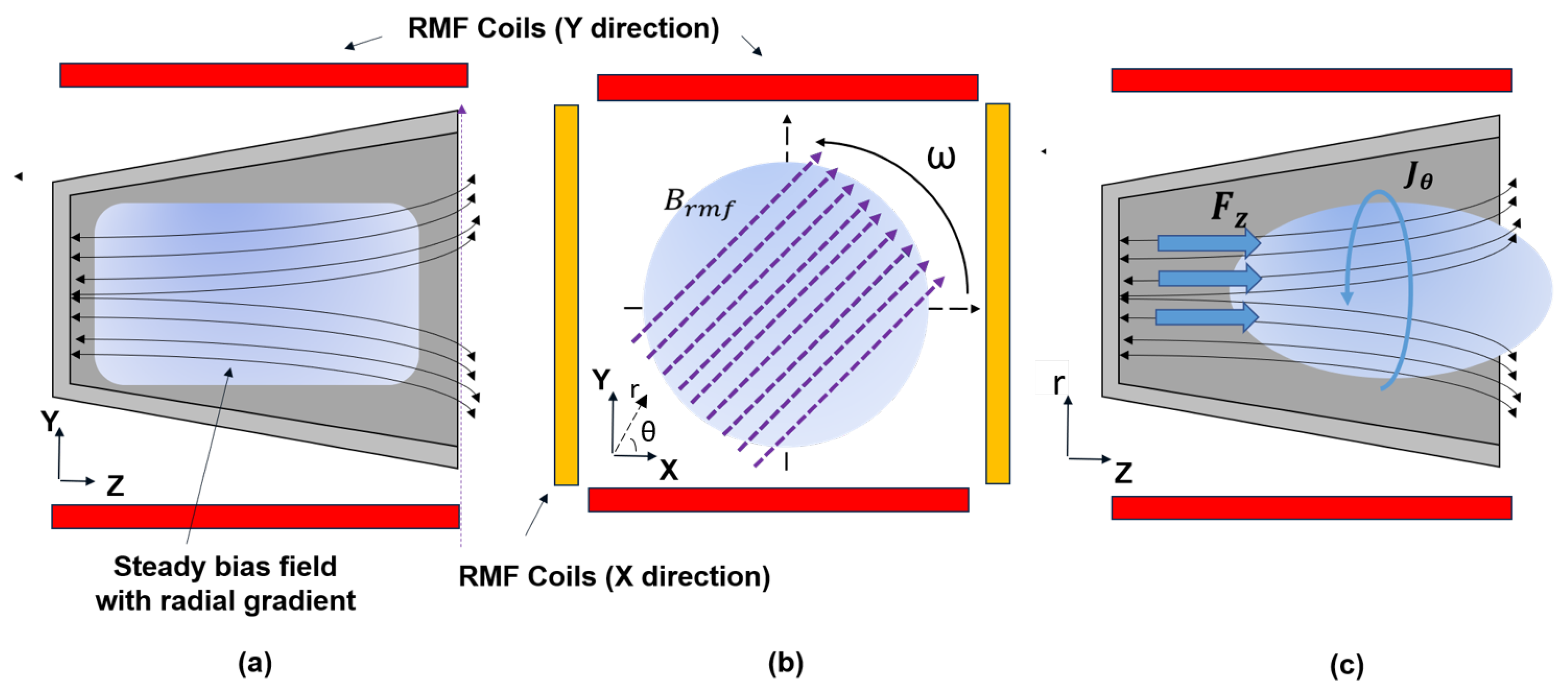
We review a simplified model for RMF-FRC operation. This model is based on the derivation first presented by Blevin and Thonemann [41]. The key elements in the formation process are illustrated in Figure 10. Neutral gas with a small amount of seed plasma from a preionizer fills the discharge chamber. This plasma is confined by a steady background magnetic field with a radial gradient, given in cylindrical coordinates as
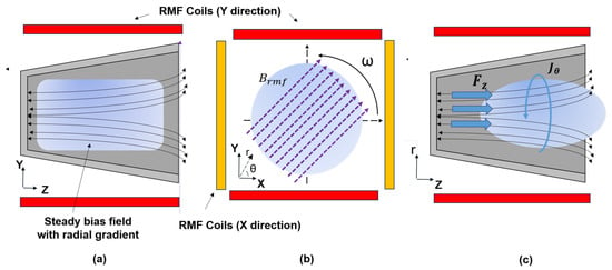
Figure 10.
RMF-FRC Operation—(a) Side view cross-section in the r-z plane of the thruster illustrating how ionized gas is injected into the discharge chamber. A steady bias magnetic field with radial gradient is present. (b) End-on view of the thruster in the r- plane depicting two sets of coils oriented in the x- and y-directions that generate a rotating magnetic field (RMF) by using sinusoidal currents at frequency applied 90° out of phase. The RMF induces axial and azimuthal currents. (c) Side view of the r-z plane illustrating FRC formation. Large azimuthal currents form the plasmoid and interact with the external radial magnetic field component to axially accelerate the plasmoid via a Lorentz body force.
Two sets of saddle coils are oriented perpendicular to each other and phase-shifted currents with frequency are driven through these coils generating alternating magnetic fields that are 90° out of phase. The combined effect of these coils creates a RMF of the form
where is the amplitude of the magnetic field. While a real RMF would have spatial variation, this idealization of the field does not. The RMF frequency should be much greater than the ion cyclotron frequency but much less than the electron cyclotron frequency to ensure that the induced ion currents are much smaller than the electron currents. The combination of Faraday’s law of induction and the generalized Ohm’s law for an infinitely long plasma column show that the time varying RMF magnetic field produces an electric field that in turn drives an azimuthal plasma current. The electron Hall parameter is defined as , where is the plasma resistivity, is the electron density, and e is the elementary charge. In the limit of low plasma resistivity, will be much greater than one and the electrons will rotate in sync with the RMF. In this case, the plasma current density as a function of radial position is:
where is assumed constant.
The azimuthal current drives field-reversal in these devices. The current gives rise to a diamagnetic field that opposes the applied magnetic field of Equation (5), reversing it close to centerline and forming a plasma body that is magnetically isolated. The above formulation, specifically Equation (7), illustrates a key advantage of RMF-FRC thrusters. In principle, if the resistivity is sufficiently low, the current that is driven in the azimuthal direction is independent of the current in the driving coils. This is in contrast to theta pinch methods or other pulsed methods that require current levels of kA or greater to generate a reversed field configuration.
There are multiple mechanisms that have been proposed to date by which RMF-FRCs may be axially accelerated to generate thrust. These include a Lorentz body force that results from interaction with the applied field [42], a self-field-derived Lorentz body force [43], and thermal-to-kinetic energy conversion [44]. We proceed with a brief discussion of each mechanism.
Lorentz body force via applied field: Slough et al. [42] proposed that the azimuthal plasma current driven by the RMF in Equation (7) interacts with the radial component of an the applied external magnetic field in Equation (5) to give rise to a Lorentz body force:
where the volumetric integral is performed over the plasma volume to yield the total force. This result suggests that the force on the plasmoid scales linearly with the RMF-driven current.
Self-field acceleration: A self-field acceleration mechanism may comprise part of the total thrust mechanism. In many RMF-FRC’s, there is a component called the flux conserver that acts to sustain a constant flux on the short timescales of FRC formation and ejection. The flux conservers consist of either metallic straps concentrically placed along the thruster cone or actually comprise the cone itself. As the plasmoid forms, the rapidly changing plasma currents produce a magnetic field that couples to the conductive material in the flux conservers. This process will in turn drive a mirror current which can act on the plasmoid. It has been proposed that the resulting force will scale as , similar to other pulsed inductive devices where J is the RMF plasma current (c.f. [43]).
Thermal-to-kinetic energy conversion: Slough et al. [42] posited that acceleration in the RMF-FRC also may stem from the conversion of thermal energy, introduced by Ohmic heating of the plasma through the RMF current, to directed kinetic energy via adiabatic expansion. In this case, the flux conservers combined with the self-contained nature of the RMF-FRC both work to prevent thermal losses to the walls of the chamber and instead redirect this energy into directed thrust. The kinetic energy of the propellant (and by extension the force) is related to the change in the enthalpy of the plasmoid as it is accelerated.
Although it is likely that all three mechanisms may contribute to thrust generation in FRC-RMF devices, to date, it is not known if one is dominant or indeed how the total thrust is distributed between these three mechanisms. This ambiguity largely stems from the lack of experimental performance measurements that would permit evaluation of the predicted scalings for each mechanism.
Review of RMF-FRC Test Articles
The potential for high performance of RMF-FRC thrusters has served as motivation for the fabrication and testing of a number of test articles. The Air Force Research Laboratory, Tokyo University, University of Washington, MSNW, and University of Michigan have all developed systems of varying capabilities. The thrusters share common design elements, namely that each has a preionizer, RMF antennae system, and a steady bias field. Additional components and capabilities may be present to suit the institutions specific experimental goals. Although these test articles have different geometries and operate at power levels (ranging from 500 W to 100s of kWs), the work on these devices shares the common goal of improving understanding of thrust generation and ultimately demonstrating performance. Unfortunately, direct thrust measurements have not been performed for these thrusters and test articles.
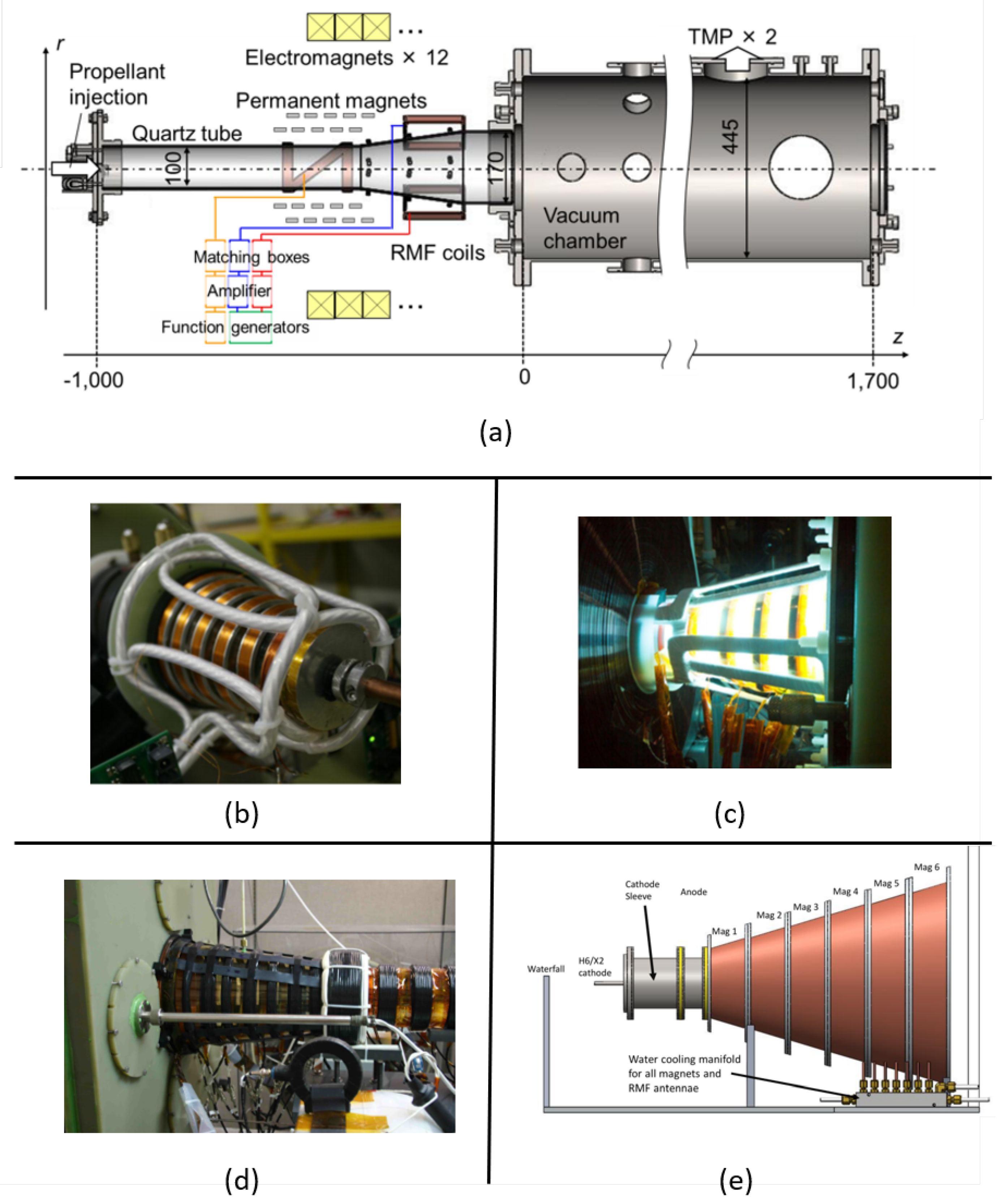
The electrodeless helicon plasma thruster (Figure 11a) leveraged the Large Mirror Device (LMD) configuration to study the acceleration of high density helicon plasmas [45]. It consists of a quartz tube that gradually expands as it enters a drift vacuum chamber. Permanent magnets placed along the tube act as a magnetic nozzle, and an RMF acceleration stage was added to the design. The helicon plasma source was typically operated at 1 kW and the RMF coil were driven at 1 MHz with a peak-to-peak current of up to 100 A. Operation of the RMF stage produced an observed increase in the axial ion velocities, which was attributed to three possible factors. The first is that the azimuthal induced current by the RMF leads to acceleration through the Lorentz body force arising through the interaction of the current and applied radial magnetic field component. Second, it was hypothesized that a strong radial density gradient forms, producing a diamagnetic current that interacts with the applied field to yield a force. Finally, an axial pressure gradient in the gas could be contributing to the thrust. Interestingly, the growth in all three possible acceleration mechanisms scales with increasing plasma density, which the RMF-driven azimuthal current promotes quite effectively [46].
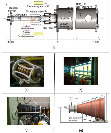
Figure 11.
RMF-FRC test articles: (a) Schematic of Tokyo University electrodeless helicon plasma thruster (from [45]; licensed under a Creative Commons Attribution (CC BY) license), (b) MSNW electromagnetic plasma thruster (from [47]; reproduced with permission of the author), (c) Air Force Research Laboratory RP3-X thruster (from [49]), (d) MSNW electrodeless Lorentz force thruster (from [51]; reproduced with permission of the author), (e) CAD model of the University of Michigan RMF thruster (from [43]; reproduced with permission of Electric Rocket Propulsion Society).
The electromagnetic plasmoid thruster (EMPT) (Figure 11b) was a low power 500–5000 W pulsed RMF device [47]. The goal of the development effort was to demonstrate continuous wave (CW) operation (up to 50 pulses) of a plasmoid thruster and its PPU. It was the first IPPT configuration to demonstrate CW operation with a steady-state propellant flow, operating at average power levels up to 1 kW. The pulse rate was 2800 Hz at pulse energies of 2 J for single pulse and 12.7 J for multi-pulse operation. The thruster consisted of a conical quartz tube with bias field magnets and RMF antennae placed along the length of the tube. It used a small electrode at the base of the thruster as a preionizer. Performance was estimated using a ballistic pendulum thrust measurement in conjunction with Langmuir probes to obtain time of flight data. Operation of the RMF at increased repetition rates resulted in greater mass entrainment and use of the propellant relative to single pulse operation. Impulses of up to 0.12 mN-s were observed for 6 ms gas puffs which generated nine plasmoids.
The RP3-X (Figure 11c) is an RMF-FRC test article with four coils that line the thruster cone and are arranged in such a way as to create the necessary rotating magnetic field [48]. The thruster itself is vacuum sealed with the exit plane attaching to a larger vacuum chamber. It can operate at a pulse frequency of 10 kHz and an energy of 5 J per pulse. It has operated on xenon propellant with an applied 300 G magnetic field [49].
The electrodeless Lorentz force thruster (ELF) (Figure 11d) was a prototype device fabricated to demonstrate high power RMF-FRC operation. It was envisioned to be scalable to 10–100 kW to compete with other high power state-of-the-art electric thrusters, specifically Hall thrusters. The inductive nature of the thruster makes it possible to operate on chemically active propellants that would damage the electrodes in other thruster options. The thruster performance is affected by the choice of propellant, but for any selected propellant the thruster is throttleable to higher power densities without any additional alterations to the overall thruster configuration [50].
The ELF preionizer consists of an electrode connected to a puff valve, which serves to partially ionize the neutral gas as it is injected. The thrust chamber consists of a 42 cm long conical quartz cavity with a 16° half-angle. The thruster is wrapped with flux conservers, which are sections of copper strap that act to conserve the total axial flux on the timescales of FRC formation and translation. Outside of the flux conservers are a series of coils that produce the magnetic bias field necessary for field reversal and plasmoid acceleration. Finally, the two pairs of RMF coils are located outside the bias coils. These are copper straps run the length of the thruster cone and are responsible for producing the large rotating magnetic fields that induces the azimuthal current. The thruster exhausts into a small vacuum chamber, which serves as a drift area permitting the study of plasmoid translation physics [44].
Although it was fabricated to operate in a CW mode at a pulse rate of multiple kHz, PPU constraints limited the number of possible pulses in a given time period. Published data center on a “standard” shot with a discharge energy of 46 J at a 300 kHz RMF frequency. Operating at this condition on nitrogen, it was estimated that 16% of the total input energy was deposited into the plasma as thermal and magnetic energy. Of that, it was further estimated that half was converted into kinetic energy, resulting in an efficiency of 8%. Radiated energy was the dominant estimated energy loss mechanism, at 78% of the total input energy [51].
The University of Michigan (UM) RMF-FRC thruster (Figure 11e) is based on the ELF design and includes lessons learned from past RMF test campaigns. The thruster is designed to operate at a pulse rate of 1 kHz, which is much faster than the characteristic response of standard thrust stands and should permit performance measurements using conventional electric propulsion thrust stands [52]. If successful, this would represent the first direct thrust measurements on an RMF-FRC test article.
The UM-RMF thruster preionizer is based on a cylindrical, lanthanum hexaboride (LaB) hollow cathode. Preionized propellant is injected through the central bore of the cathode, with additional neutral propellant injected in a ring-pattern surrounding the cathode. The bias field is generated by six conically arranged aluminum bobbins wrapped in magnet wire which also act as the thruster cone. The cone half angle is 16°. Each bobbin measures 7 cm in length and is electrically isolated from the other bobbins to prevent eddy currents from developing along the length of the cone. Embedded between the magnet wire and bobbins is a cooling loop to mitigate thermal loading when operating the magnets at high currents (∼10 A each). The bias coils are designed to provide a peak centerline axial field of 300 G. Lining the inside of the thruster cone are two RMF antennae, each consisting of two current loops arranged in an orthogonal orientation with respect to each other. The antennae consist of 0.25-in diameter copper tubing. Cooling water can be flowed through the antennae when operating at higher power levels. The system baseline is to operate with a peak current of 4.5 kA, which was selected to ensure full penetration of the RMF field into the plasma [43].
At a 1 kHz pulse rate, the average input power to the UM-RMF thruster is approximately 30 kW per antenna. The capacitor banks in the PPU can be changed to produce different RMF frequencies. A set of 24 F and 660 nF capacitor banks have been constructed to provide RMF frequencies of 20 kHz and 300 kHz respectively. The antenna, PPU circuit elements, magnetic field strength and shape, and amount of seed plasma can all be varied, permitting the exploration of a wide parameter space. This test article has yet to be operated. The current status of the UM thruster as of the writing of this article is that it has been assembled but has not been operated.
Technical Obstacles to Testing
There are a number of technical challenges in implementation and operation of RMF-FRCs. The high voltages necessary to drive the RMF currents in the antennae can result in electrical arcing to the surrounding conducting material. The large currents can give rise to excessive heating of the circuit and thruster components. Many thrusters are attached to a flange on a vacuum chamber and eject the plasmoids into a weaker bias field, making it difficult to confirm detachment of the plasma from the applied field. It is also challenging to operate the various circuit components at high power levels (10 kW and greater). Coupling the power into the thruster is hampered by losses to the surrounding structure and resistive losses in the the circuit components. Losses can be mitigated by placing the PPU near the thruster in the vacuum facility, but this introduces issues related to high-voltage arcing and thermal loading in the PPU itself. Finally, operation at high power requires sufficiently high pumping speeds to maintain low background pressures for extended periods of time.
2.2.3. Annular FRC Thrusters
The annular FRC thruster (AFRC) is a variation on the theta-pinch FRC that uses two sets of coils to drive an azimuthal current in the plasma [53], as illustrated in Figure 12. In this implementation, the plasmoid forms in the annulus between the two coils. The AFRC was proposed as an alternative to theta-pinch FRCs as the former can operate at lower voltages (1 kV compared to 10 s of kV) and the addition of the second coil permits the formation of the plasmoid on much shorter time scales relative to the standard theta-pinch FRC. If the outer coil is angled, the magnetic field has an axial gradient and the radial magnetic field component couples with the azimuthal current to yield a Lorentz body force that accelerates the plasmoid. The use of two coils also introduces more flexibility and control of the acceleration process. The inner coil is primarily used to add flux to the plasmoid while the outer coil provides a counter pressure to confine the plasma. The coils can be operated synchronously or independently, although the latter requires the addition of a second power supply [54].
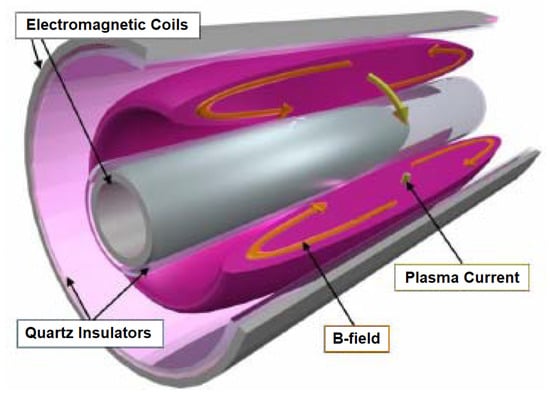
Figure 12.
Diagram of an AFRC thruster (from [53]).
The first AFRC device was developed in 1963 by Phillips et al. [55] to study the formation physics of plasmoids for fusion experiments. Several other groups implemented similar configurations, and in 1967 Alidieres et al. [56] demonstrated the first translation of an AFRC plasmoid. To accomplish this, a radial magnetic field created by an iron circuit was introduced. While translation speeds of up to 200 km/s were observed, energy conservation analyses indicated that only a small fraction of the plasma was accelerated.
The use of the AFRC for high power electric propulsion was first realized in the experimental coaxial field reversed configuration thruster (XOCOT) [57]. The first stage of the experiment, dubbed XOCOT-S, was a study of AFRC plasmoid formation on argon and xenon. The device operated at discharge voltages of less than 1 kV with peak discharge energies of 1.1 kJ. The experiments explored the production of high density plasmas, although it was noted that insufficient preionization resulted in poor formation during the first half cycle of the discharge.
Knowledge gained from the XOCOT-S experiment was used to inform the second stage of the study, the XOCOT-T3, shown in Figure 13. The experiments performed by Hill [54] aimed to study the translation of AFRC-generated plasmoids. The outer coil was angled to introduce the radial magnetic field component necessary to yield the Lorentz body force that would accelerate the plasma. The coils were operated in a parallel mode powered by a single pulsed supply at frequencies of 10 kHz and 20 kHz and discharge energies of 0.1, 0.5, and 1 kJ/pulse. Magnetic field probes observed plasmoid formation between the coils, but for all conditions tested there was no evidence of plasmoid translation and no downstream observations of coherent plasmoid structures. Plasmas that did appear downstream were attributed to a thermal jet escaping from the AFRC.
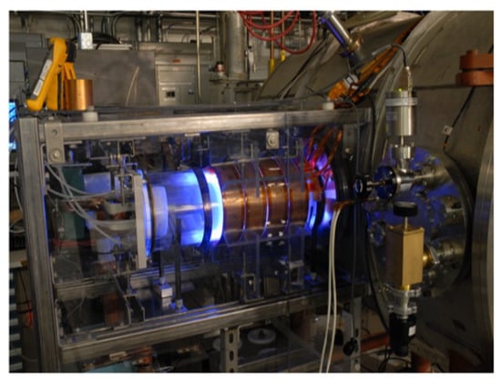
Figure 13.
XOCOT-T3 experiment (from [54]; reproduced with permission of the author).
Three hypotheses were put forth to explain the failure of the plasmoid to translate. The first is that there was an inherent induction limit for the system which limited the current driven in the plasma to levels insufficient to form a plasmoid. The second is that the plasma had low electrical conductivity, owing to low electron temperatures, resulting in rapid magnetic field diffusion that short-circuited the FRC formation process. It was determined that temperatures greater than 20 eV could reduce the rate of magnetic field diffusion to the level that would permit plasmoid formation. Finally, a plasma instability of some type could have resulted in the destruction of the plasmoid before it was able to translate downstream. As of this writing, measurements have yet to validate any of these hypotheses.
2.3. Summary of Experimental Data
Presented in Table 1 is a summary of operating parameters and test data measured for various IPPTs. In this table we have only listed the thrusters for which there exists at least a partial record of data in the literature. Most telling is the lack of data to quantify the performance of most of these thrusters. To develop greater understanding of IPPTs and facilitate future modeling efforts, future test campaigns must focus on gathering more complete sets of data on the performance and operating conditions of different thruster concepts.

Table 1.
Summary of operating parameters and test data for various IPPTs. (* data not available, ** equivalent circuit voltage, *** equivalent circuit current, estimated value, not applicable).
3. Review of Modeling Techniques
Multiple modeling techniques have been applied to IPPTs over the years, from simple one-dimensional models to full two- and three-dimensional magnetohydrodynamic (MHD) approaches. In the following section, we review the various models employed to develop an understanding of IPPTs and note the major insights gained with each model.
3.1. Open Magnetic Flux Thrusters
The modeling of open flux thrusters has primarily focused on modeling the acceleration process and capturing the electromagnetic coupling between the external primary circuit and the accelerating plasma circuit. Most models for these types of thrusters assume that the gas is already ionized to a sufficient degree to conduct current, and while some of the models do permit additional ionization during the discharge, they do not account for the initial breakdown process.
3.1.1. Planar Thruster Modeling
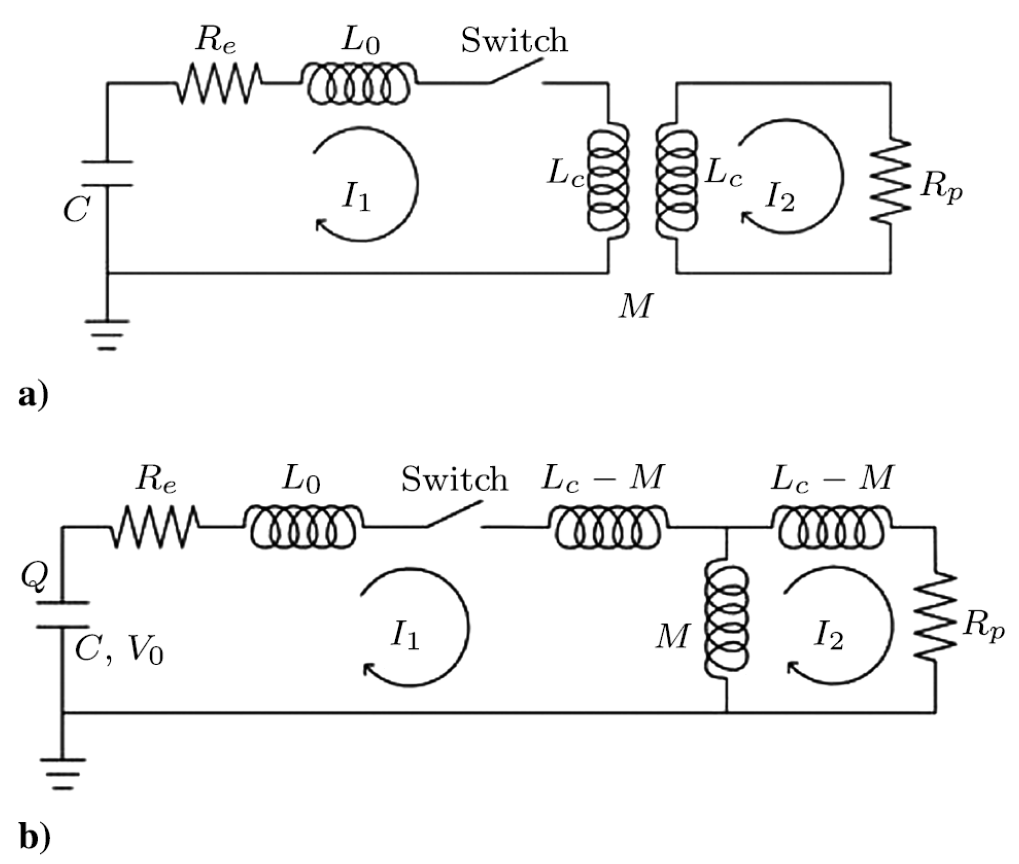
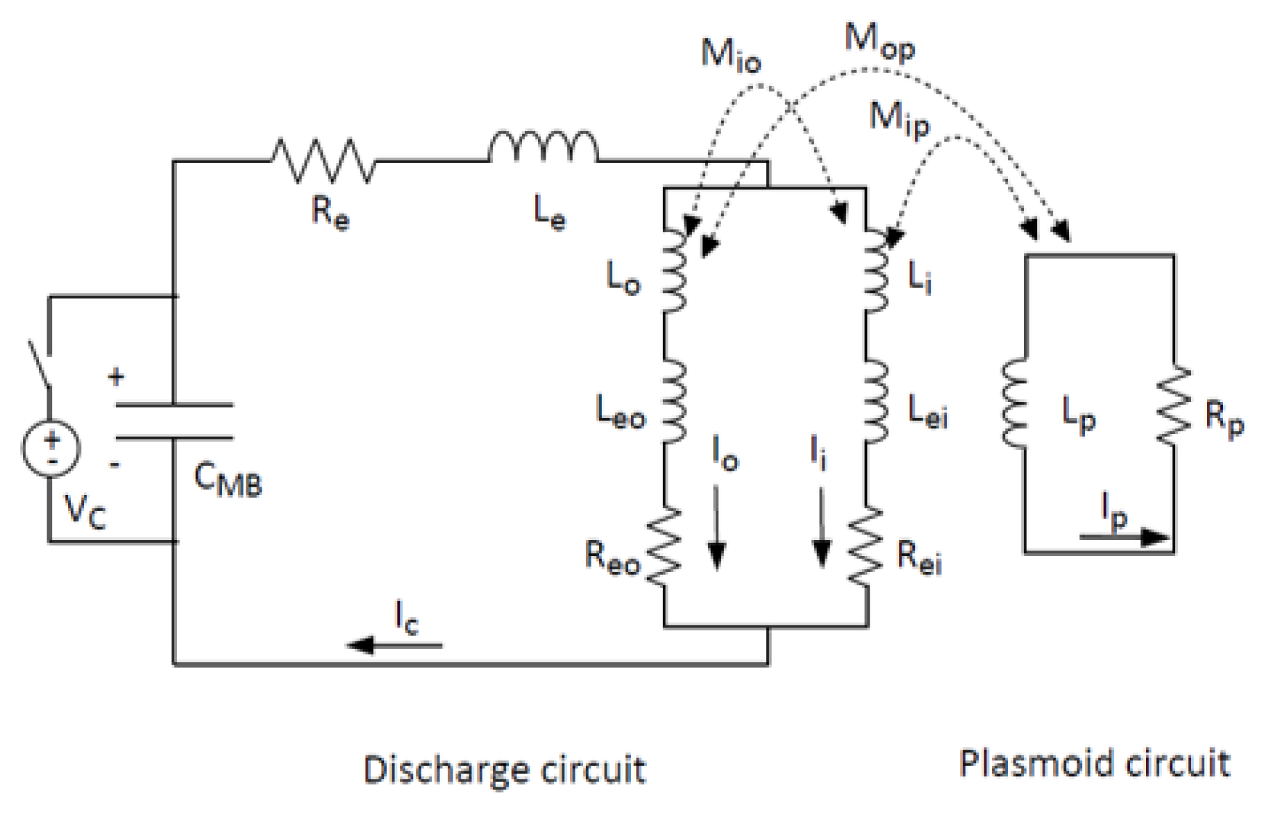
The primary model used for planar IPPTs in the literature for several years is a lumped-element circuit model coupled to a one-dimensional momentum equation [3,7,13,59,60]. The circuit can be drawn in the manner shown in Figure 14a. In the figure, the initial charge voltage on the capacitor C drives current in the primary circuit, through circuit elements with external resistance , stray or parasitic inductance , and coil inductance . The primary circuit couples to the plasma like a transformer with mutual inductance M between the circuits. An induced secondary plasma current is driven through an inductance and a plasma resistance . It is straightforward to rearrange the circuit into the equivalent configuration shown in Figure 14b, and this permits the writing of first-order ordinary differential circuit equations that can be used to numerically solve the electrical problem.
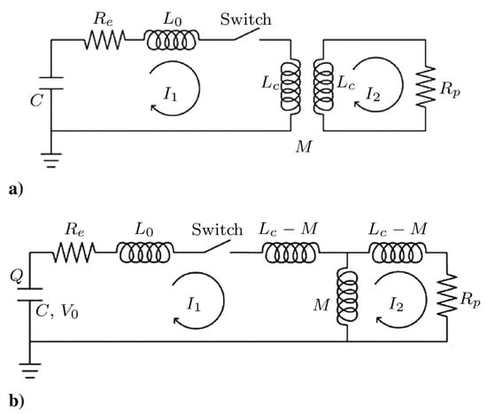
Figure 14.
Circuit models: (a) general lumped-element representation of an IPPT and (b) equivalent circuit (after [16]).
The key to coupling the circuit equations and the motion of the plasma lies in the mutual inductance term, which is a function of the separation distance between the primary and secondary circuits. This dependence can be found experimentally using a conducting metal disk to simulate the plasma at different downstream positions [13], or it can be found numerically using a solver to simulate the magnetic field as a function of plasma position [19,59,61,62]. Since the acceleration problem has no closed form solution and must be calculated numerically, it is straightforward to use a table lookup for the mutual inductance function. However, it has been found and validated in several studies that the mutual inductance for a planar IPPT can be curve fitted using a function of the form
where z is the axial direction of motion of the plasma and the curve fit parameter is the decoupling length, which represents the characteristic length scale of electromagnetic interaction between the two circuits.
The axial linear propellant density distribution in front of the coil is and it can assume several potential configurations. The plasma sheet is assumed to possess an initial mass of propellant and to entrain and accelerate to the sheet speed all propellant encountered as the sheet moves. The overall mass in the sheet is
where is the time-dependent velocity of the plasma. Finally, the momentum of the plasma is governed by the equation
where the term on the left side of the equation represents the electromagnetic force on the plasma, the first term on the right side represents the momentum invested in accelerating the already-entrained propellant, and the second term on the right side represents the momentum that must be expended to entrain propellant encountered by the plasma, ‘instantaneously’ accelerating it to the current sheet speed.
While the model is relatively straightforward to solve, a simple examination of the governing equations reveals much about the nature of these thrusters and their operation. The mutual inductance in Equation (9) and the corresponding electromagnetic force in Equation (11) both decrease exponentially as a function of separation distance, showing the importance of accelerating the propellant while it is near to the coil face. In addition, the last term in Equation (11), which involves the entrainment of propellant encountered by the moving plasma, reduces the useful additional acceleration that can be performed for a given level of electromagnetic force, implying that neutral propellant should be entrained early in the discharge cycle when the plasma velocity is still low so as to reduce entrainment losses.
Polzin et al. [16,60,63] nondimensionalized the one-dimensional coupled equation set and generated solutions over the parameter space represented by the remaining nondimensional parameters to gain insight into the performance scaling trends in planar IPPTs. This work provided a mathematical foundation to understand findings in the PIT MK V and MK Va data that had previously been explained through less rigorous experimental intuition. The most important new finding was the derivation of a dynamic impedance parameter
where is the initial charge voltage on the capacitor bank. It was shown that this term can be decomposed into several dimensionless ratios, with the most insightful being a ratio of the natural period of the external circuit to the time interval over which the motion of the plasma will increase the inductance of the external circuit by one unit of . Another independent circuit model study found substantially similar results [59]. A broad maximum in efficiency as a function of was discovered, and it was further shown that the operating parameters of the MK Va spanned a range of that included the maximum efficiency from the modeling, with a reduction in efficiency of only a few percent at the extremes of the experimental data range. The values of computed for the MK V, on the other hand, were more removed from the values that yielded maximum efficiency, explaining the lower performance relative to the MK Va. The work also rigorously showed that greater acceleration occurred for highly underdamped circuits and for propellant distributions where most of the injected mass was close to the acceleration coil. This combination of conditions results in high peak currents and correspondingly high accelerating forces while the plasma and coil are still near enough for appreciable acceleration to be imparted to the former.
The one-dimensional acceleration model was upgraded to include the time-evolution of energy in the plasma and to more realistically represent the plasma state properties [64]. Simulations were useful in calculating the partitioning of energy between different energy sinks in the plasma as a function of time and the controllable parameters of the discharge. An examination of the relative magnitudes of these different sinks highlighted the less-useful dissipative modes that could increase at the expense of useful plasma acceleration.
Mikellides et al. [65,66,67] performed 2-D axisymmetric modeling using the multiblock arbitrary coordinate hydromagnetic (MACH) code. This was the first major time-dependent simulation of the plasma evolution using an MHD solver, though a pair of upgrades had to be implemented during the course of the research to improve the results. In the most recent simulations, at each timestep the computed magnetic field and plasma resistivity were integrated over the solution domain and used to insert the effects of time-varying resistive and inductive plasma circuit voltage losses into the model governing the solution for the time-dependent external circuit current [67]. Also, a new non-equilibrium equation of state model for ammonia was developed and included to more accurately model the MK Va data [68].
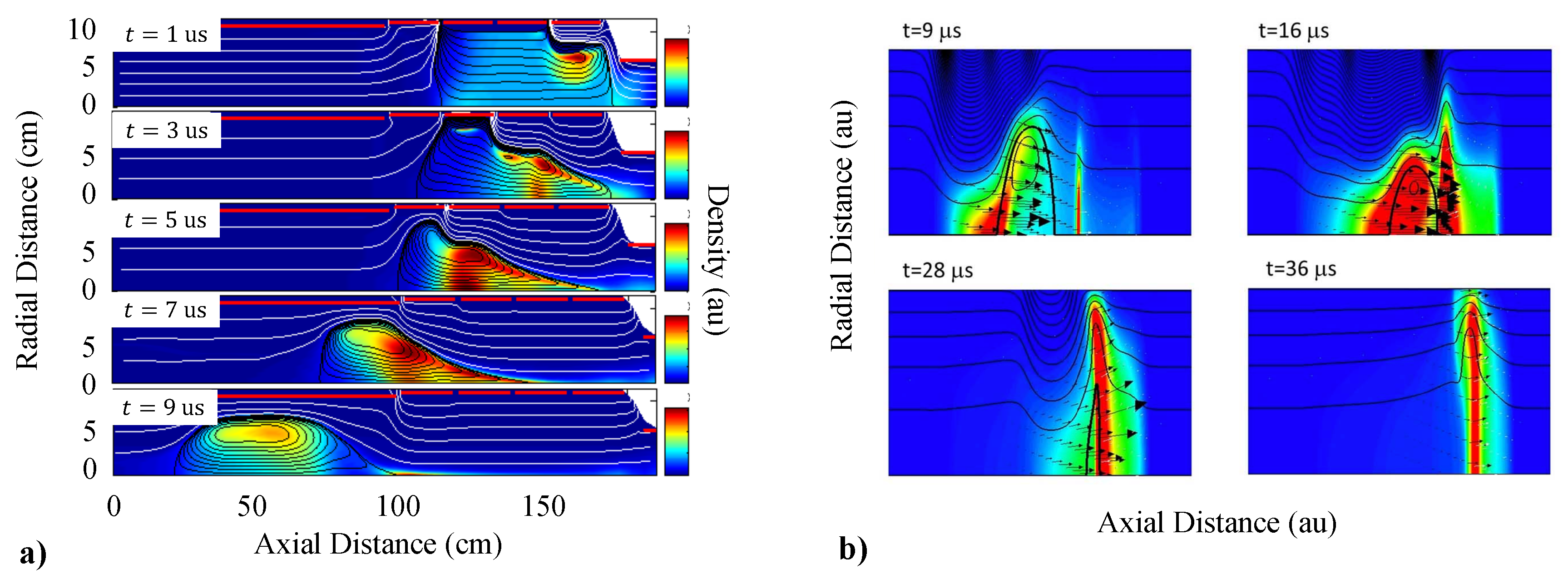
The MHD modeling provided some interesting insights into planar IPPT operation [7,66,67]. A good match was obtained for the first half-cycle of the external circuit current and the computed thruster performance mostly exhibited good quantitative agreement with the MK V and MK Va experimental data for multiple propellants. The time-evolution of the plasma in two dimensions was insightful in showing first that the plasma maintained remarkable radial uniformity and also in demonstrating the amount of accelerated plasma that impacted the central cone located downstream from the acceleration coil face that was used to inject gas into the thruster. A critical specific energy beyond which efficiency declined was identified in these results and in computations on a lower discharge energy variant [69]. The specific energy beyond which efficiency declines exhibits good quantitative agreement with experimental data. The modeling of performance on ammonia also exhibited very good quantitative agreement with the far more simple and less computationally intensive one-dimensional coupled performance model. As the latter did not contain radiation energy losses, this agreement supported the conclusion that radiation losses in the PIT operating on ammonia were small or negligible.
Che et al. [70] presented a two-dimensional axisymmetric MHD model of an IPPT using a formulation that coupled the external circuit with the plasma circuit electrical response. In this work, a separate domain for the drive coil was used to calculate the plasma voltage component presented to the external circuit. This was found by integrating the azimuthal electric field along the path of one of the spiral wires comprising the acceleration coil. While a planar coil was studied in this work, this approach allows for the calculation of the plasma voltage presented to non-planar external coil geometries as well. Computational domains outside the thruster body were also added to help determine the effects of nearby conductive structures, namely the walls of a conductive vacuum chamber and a coaxial capacitor mounting plate located behind the drive coil. It is worth noting the plasma was assumed to be in local thermodynamic equilibrium (LTE) and electrons, ions, and neutral particles as having the same temperature. This is in contrast to the model of Mikellides et al. [65], where thermal non-equilibrium between ions and electrons was allowed with each with their own energy equation.
Using their model, Che et al. [70] simulated the PIT MK I and obtained several interesting results. A secondary current sheet was observed to form when the current in the drive coil reversed sign during the second half period of the discharge cycle. This secondary sheet was found to contribute up to ≈20% of the total impulse and did not “short-circuit” the primary current sheet. It was also observed that and could be kept relatively constant over a range of discharge energies so long as was adjusted to maintain a constant specific energy (). A critical specific energy beyond which efficiency declined was not observed within the simulated range of parameters. This may be due to the fact that the design parameters of the MK I place it well outside of the range of optimized efficiency achieved in the MK Va thruster. Third, compression of the initial propellant in the direction of the coil face was found to noticeably improve thruster performance. Reducing radial non-uniformities was also found to positively affect propulsive performance to a lesser extent. Finally, conductive structures located within the decoupling distance of the drive coil were found to adversely impact thruster performance. The effect was most severe for the interaction with the coaxial grounding plate located slightly behind the drive coil. Structures located beyond the decoupling distance were found to have minimal impact, which is in agreement with previous results obtained using the one-dimensional coupled performance model [62].
3.1.2. Conical Theta-Pinch Thruster Modeling
Hallock et al. [19,71] attempted to expand the one-dimensional plasma acceleration model coupled to the lumped-element circuit model by modifying it to include the inherent two-dimensional plasma motion found in CTP-IPPTs. The keys to this work were magnetic field modeling results and experimental measurements used to determine the functional variation in mutual inductance between the conical acceleration coil and the plasma moving in either the axial or radial direction. Putting this into the equation of motion yielded accelerating electromagnetic forces in both the axial and radially-inward directions, corresponding to the directions of negative gradient in the mutual inductance. This work did not address the problem of mass entrainment, instead assuming all propellant mass was initially in the plasma at the start of the discharge. The biggest shortcoming of the model was the lack of a mechanism to convert radial motion of the plasma into axial momentum. Finally, while computations were performed for certain cone-angles, the resulting computational model could not be readily applied to a cone of arbitrary angle.
There were some interesting insights from this effort, despite some gross assumptions incorporated into the model. With a second degree-of-freedom in the equations of motion, the plasma can electromagnetically decouple from the coil moving radially as well as axially, and rapid radial displacement results in a significant reduction in axial acceleration of the propellant. It is tempting to think that this radial motion could be converted into axial motion, but that conversion will certainly incur some additional losses due to increased entropy of the gas. This strongly favors the planar IPPT configuration over the CTP-IPPT, where in the former energy is coupled from the circuit directly into motion of the plasma in the preferred, axial direction without the need for additional processes to turn the flow and generate thrust.
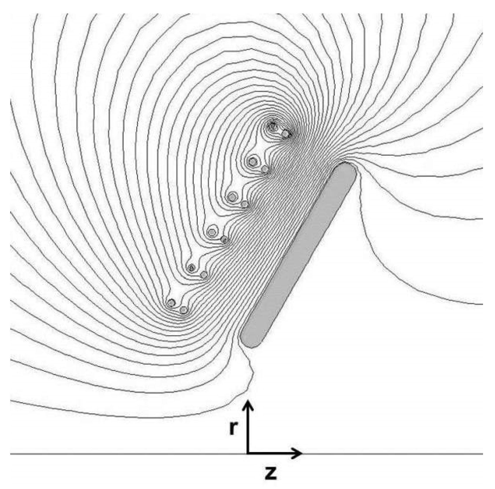
Martin [72] also developed a circuit model coupled to radial and axial equations of motion to investigate the performance of conical IPPTs with cone angles from 10° to 90° (i.e., planar), treating the plasma as a radially compressible slug conformal to the coil. The mutual inductance was calculated using the magnetic field solver QuickField for a variety of plasma locations, with the plasma modeled as a slug with finite dimensions and a large conductivity. Flux contours for one such calculation, with a six-fold parallel 2 turn coil with cone angle of 60° is shown in Figure 15; this coil is equivalent to the FARAD coil from Ref. [73] if it were folded in to the specified cone angle. From these results, the total magnetic energy in the configuration is calculated, and from those are derived the plasma position dependent mutual inductance values, which are stored in a look-up table and used for interpolation during solution of the coupled circuit/dynamic equations. The radial equation of motion included a restoring force due to the plasma pressure which was computed with a simplified equation of state. The results of this model agreed with those of Hallock et al. [19,71] described above; in particular it predicted that the maximum efficiency will be attained by a planar coil. These calculations also found a local maximum in the efficiency (though not an absolute maximum) for a cone angle less than 90°, as was observed experimentally in Ref. [4].
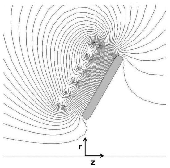
Figure 15.
Magnetic flux contours calculated with QuickField for a coil with six two-turn leads in parallel and a cone angle of 60°. The plasma thickness is 1 cm. The overall dimensions of the coil are similar to the FARAD coil of Ref. [73].
3.2. Closed Magnetic Flux Thrusters
Modeling of closed magnetic flux thrusters has focused mainly on understanding FRC formation and plasmoid acceleration and the impact these processes have on thruster performance. We review here in increasing order of complexity the modeling approaches that have been applied to date for FRC thrusters. These include simple scaling laws, equivalent circuit models, and high fidelity full plasma simulations. In each case, we discuss the model predictions for the key performance metrics such as specific impulse, efficiency, and thrust.
3.2.1. Thruster Scaling Laws
Scaling laws are simple analytical expressions that relate thruster operating conditions and geometry to performance metrics. IPPTs are inherently complex devices. High fidelity models are required to fully capture the physics involved in thrust generation. However, those codes require significant computational time and complexity, and it may be difficult to determine physical scaling relations from the simulation results. To circumvent this issue, scaling laws can sometimes be found by applying numerous assumptions to a model to arrive at first order expressions that capture, to an extent, the effects key physical processes have on performance.
Efficiency from Energy Conservation
The model introduced by Slough et al. [42] is predicated on the assumption that acceleration of the RMF-FRC is a two stage process. First, the plasmoid is accelerated by a Lorentz body force that arises from the interaction of the azimuthal plasma currents and the external magnetic field. Second, any thermal energy introduced into the plasmoid through Ohmic heating during FRC formation is recovered through adiabatic expansion. To arrive at a tractable analytical expression for the work performed by the Lorentz body force, this model employs the assumption of constant FRC plasma properties in a conical geometry with fully magnetized electrons (see Figure 10c). The kinetic energy delivered to the plasma by the Lorentz body force can be written as
where is the average radius of the plasmoid, is the length of the thruster cone, is the magnitude of the externally applied magnetic field, and the cone half angle of the thruster is given by . Physically, this result shows that the energy of the propellant will increase with the size of the thruster, the plasma density of the plasmoid, the RMF drive frequency, and the strength of the external magnetic field [42]. The conversion of thermal to kinetic energy is found by balancing the plasma and magnetic pressures to yield
where . Here, is the initial plasma temperature before expansion and T is the temperature after the plasmoid is ejected. Equation (14) indicates that the thermal energy converted to kinetic energy scales as the square of the externally applied magnetic field. The total efficiency is found by summing Equations (13) and (14) over the total energy expended in the system. Weber [51] identified each of the relevant energy loss modes to further deconstruct the energy flow in the system to find an overall scaling law for efficiency:
The energy sinks in the denominator are: kinetic (), thermal and magnetic (), ionization (), resistance in the flux conservers (), screened RMF (), convection (), and radiation () energy losses. Not included are the losses in the driver circuit, so Equation (15) only accounts for the energy imparted to the plasma by the RMF.
While Equations (13) and (14) are predictive, provided the underlying assumptions are valid and the plasma density is known, Equation (15) for the accelerator efficiency is not. This phenomenological model has been successfully used in understanding the contributions of different energy loss mechanisms to thruster efficiency at a given operating condition. In analyzing experimental data from the ELF thrusters, for example, it was found that the overall estimated efficiency was 8%. The scaling model was used to show that the dominant efficiency loss term was radiated energy (78% of total energy), and that the conversion of total thermal and magnetic energy to kinetic energy was approximately 50% [51].
Performance Metrics from Asymptotic Analysis of Equivalent Circuits
Woods et al. [74] derived analytical scaling laws for the impulse, thrust, and efficiency using an asymptotic treatment of an equivalent circuit model of an RMF-FRC. Specifically, they examined the case of high RMF field strength where the electrical load presented to the driving circuit by the plasma can largely be neglected. Subject to the further simplifying assumption that the plasma can be represented as a cylinder with constant density, they found the following results for impulse (I), maximum force generated by the thruster (), and efficiency ():
Here is the damping constant of the circuit, is the initial input energy, N is the number of turns in the RMF coils, C is the capacitance, L is the inductance, is the background radial magnetic field strength, is the RMF frequency, and is the length of the RMF coils. The plasma slug has a length and radius of and , respectively, and a mass of M.
Holding all other parameters constant, Equation (16c) suggests that there is an optimal input energy to achieve a maximum efficiency. Physically, the reason for this is believed to be related to current generation as described in Section 2.2.2. The maximum current arises when the electrons are fully magnetized. Increasing the initial discharge energy from a low value increases the magnetization of the electrons, leading to increased thrust efficiency. However, after the electrons are fully magnetized, any further increase in is wasted, decreasing overall efficiency. This predicted optimum efficiency as a function of has yet to be experimentally validated, and we note more generally that these scaling laws have yet to be compared against an actual experimental configuration.
Challenges in Deriving Scaling Laws
While scaling can provide fundamental physical insights into the physical processes in a thruster, the assumptions used to arrive at these analytical descriptions generally restrict the applicability of these scaling laws to limited cases. There are ongoing efforts to expand the set of scaling laws associated with RMF-FRC operations, and to validate and verify these scalings laws against experimental data. However, using lower-fidelity or simplified models to capture the complex interactions of the plasma and the external circuit and going even further to relating those results to performance metrics has proven to be difficult.
3.2.2. Equivalent Circuit Models
Following the standard approach that has been applied in the past to several IPPTs, there have been attempts to represent FRC thruster operation with equivalent circuit models. Circuit models fill an intermediate niche between low fidelity scaling laws and high fidelity plasma simulations. Depending on the model, significant scaling insight can be gained without the extensive loss of key physics. However, it can prove challenging to capture the important processes represented by different parameters, such as the mutual inductance, in a tractable way that clearly relates them to thruster operating conditions and geometry.
Equivalent Circuit Model for a Stationary Plasmoid
Hugrass et al. [75] were the first to derive a circuit model for RMF-FRCs. It includes a time varying model for the penetration of an RMF into a plasma and links the process back to circuit components. The model is not for propulsion purposes, and thus it does not include the axial acceleration of the plasma.
The RMF is driven by a set of two coils of infinite length acting on a plasma column of fixed density, also of infinite length (as shown in Figure 16a). By solving Ohm’s, Ampère’s, and Faraday’s laws, a set of partial differential equations (PDEs) for the axial magnetic vector potential are derived in cylindrical coordinates r and and in time t. These fields are associated with the transverse fields produced by the coils and plasma currents, and the axial, applied magnetic field. The applied field is a steady-state background field that is modified by the reverse field produced by the RMF and induced azimuthal plasma currents. The model revealed significant transient effects as the RMF penetrates into the plasma. The steady azimuthal current expected of an RMF current drive was observed after full penetration and magnetization of the electrons. Also after achieving full penetration, the inductance presented to the circuit by the coils approaches that of the unloaded case while the resistance increases as energy is deposited into the plasma.
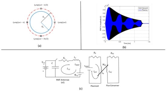
Figure 16.
(a) Geometry used to model the coil and plasma coupling in Ref. [75], (b) current waveforms of an ELF discharge with and without a plasma in the thruster (from [51]; reproduced with permission of the author), (c) equivalent circuit model of an RMF-FRC with flux conservers (from [43]; reproduced with permission of Electric Rocket Propulsion Society).
Calibrated Equivalent Circuit Model to Estimate Energy Deposition in FRC
Weber [51] used a simple circuit model to estimate the energy deposited in the plasma based on experimental measurements for the ELF thruster. The load of the plasma is modeled as a resistance term that can be substituted into the circuit. The waveform produced in the circuit model was adjusted by changing the characteristic plasma resistance until the model matched the waveform recorded when the ELF thruster was discharged. This characteristic resistance was then used to calculate the energy absorbed by the plasma. Experimental current waveforms of an ELF discharge with and without a plasma in the thruster are shown in Figure 16b. For a standard shot, the absorbed energy was calculated to be 46 J.
Circuit Model for Second Stage Acceleration of an FRC Plasmoid
Little et al. [76] used a lumped circuit to model the second stage for an RMF-FRC, which consisted of a series of flux coils downstream of the RMF coils. The flux coils are pulsed as the plasmoid traverses downstream, adding energy to the plasmoid while the latter simultaneously pushes or entrains neutral gas as it translates. The equivalent circuit is similar to those in other inductively coupled closed magnetic flux thrusters. The driving circuit consists of a charged capacitor discharged through an circuit that is coupled to the plasmoid, represented as a separate circuit, through a mutual inductance term.
Expressions for the mutual inductance were derived using plasma current equilibrium expressions [77]. The interaction between the external discharge and the plasmoid current gives rise to an axial Lorentz force. As the model includes only the effects of a coil placed downstream of the RMF region, it is unable to predict initial plasmoid formation and acceleration. The model, however, did show good agreement with experimental data. [76].
Equivalent Circuit Model for FRC Translation including RMF Coils
Woods et al. [43] presented a one-dimensional slug model for the acceleration of a plasmoid in an RMF-FRC (Figure 16c). In this model, each antenna is modeled as an circuit coupled to a plasma possessing finite resistivity. The plasma is a conducting slug of fixed cylindrical geometry and constant, uniform density in r and . The plasma also couples to a flux conserver. Expressions for the flux linked by the plasma to the RMF antennae, and the emf that drives the plasma current, , were derived, but to find this coupling the self-inductance of the plasma was neglected. The acceleration of the FRC consists of two effects. The first is an electron Hall parameter scaling written as and stemming from the RMF driven current interacting with the radial magnetic field. Thus, for sufficiently strong rotating magnetic fields, the Lorentz body force on the FRC reaches a maximum value. Acceleration also arises due to the interaction of the magnetic field produced by the circulating plasma current and the induced currents in the flux conservers. This has a current scaling as seen in other IPPTs [61]. There are ongoing efforts to better understand the mutual inductance coupling between the plasma and RMF currents.
Equivalent Circuit Model for Annular FRC Translation
Hill [54] introduced a circuit model coupled to a one-dimensional translation model for an annular FRC plasmoid represented as a slug. The circuit diagram in Figure 17 depicts a capacitor connected in parallel to two inductors representing the inner and outer driving coils. Each coil separately couples with the plasma through a mutual inductance term. These terms were calculated using the COMSOL finite element program by modeling the plasmoid as a metal slug and moving it to different axial locations relative to the coils. An empirical expression was derived from the simulation data, with the mutual inductance decreasing exponentially with axial location, similar to other inductive plasmoid thrusters. The force on the plasmoid is calculated as the axial change in magnetic energy coupled to the plasmoid by each coil. No thermal effects are considered in the model. The force scales as the sum of the square of each coil current times the axial change in mutual inductance. The model was non-dimensionalized and a genetic algorithm was used to optimize the design for peak acceleration efficiency. To date, this model has yet to be validated with any comparisons against experimental data [78].
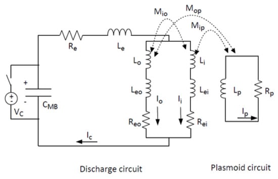
Figure 17.
Equivalent circuit model of an AFRC (from [54]; reproduced with permission of the author).
Challenges with Equivalent Circuit Modeling
A key challenge for equivalent circuit modeling is accurately capturing the coupling between the plasma and the RMF coils through mutual inductance terms. Both Hugrass et al. [75] and Woods et al. [43] derived flux coupling terms to represent these effects. However, the former derived a complicated PDE system that can only be solved numerically, limiting the scaling insight that can be gained. The latter arrived at a more tractable ODE (in time) representation, but this came at the cost of neglecting the self-inductance of the plasma. The model also does not account for the process of RMF penetration into the plasma, and the FRC equivalent circuit models do not contain modeling of any thermal effects. This poses a potential problem as there is evidence that adiabatic expansion of the plasma may be a key acceleration mechanism [51]. There are ongoing efforts to model these processes within the circuit elements (such as the mutual inductance) that can be calibrated to match experimental data but still retain the simplicity and insights that can be gained using equivalent circuit models.
3.2.3. High-Fidelity Models
High fidelity simulations represent the most complex form of thruster modeling. The physical processes the model can capture are limited to the numerical code used. While codes can be expanded to account for a range of effects, this comes at the cost of computational time and it may be difficult to use the results to determine the physical mechanisms driving performance. Nevertheless, high fidelity modeling is a powerful tool for predicting performance of a thruster and in particular it can be leveraged to model in-space performance.
Magnetohydrodynamic (MHD) Fluid Models
The MHD code Moqui has been used extensively to model the plasma dynamics of FRC formation and translation [79] (example results presented in Figure 18a). Moqui features an adaptive grid that is able to identify and move with a translating FRC. The solver is able to increase the grid resolution in regions of strong magnetic field and high pressure gradients. This approach provides a balance between physical fidelity and computational efficiency that has proven to be valuable during the preliminary design and analysis of FRC thruster experiments, including PTX, MAP, and ELF.
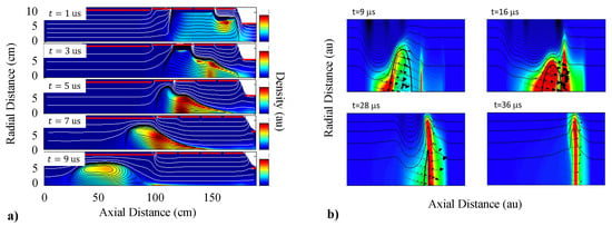
Figure 18.
Numerical simulations of FRC thrusters: (a) Moqui simulation showing acceleration of a plasmoid using sequentially pulsed magnets (from [80]; reproduced with permission of Electric Rocket Propulsion Society), (b) SEL-HiFi simulation shows neutral entrainment by a translating FRC (from [81]; reproduced with permission of the author).
Entrainment of neutral particles by a translating FRC has been investigated using the three-dimensional MHD code SEL-HiFi [81] (example results presented in Figure 18b). The plasma-neutral interaction was modelled by adding equations for ionization, recombination, and charge exchange between the plasma and a neutral fluid. Simulations showed that the response of the neutral gas to the passing FRC exhibited a strong dependence on electron temperature. For eV, downstream neutrals were entrained primarily through ionization, whereas charge-exchange collisions dominated for eV. Momentum is transferred to the neutral gas in both cases, however, frozen flow losses increase with increasing ionization reaction rates. For this reason it was concluded that charge-exchange is the most energy efficient process for neutral entrainment in FRC thrusters.
Two-Fluid Models
RMF-FRCs are inherently complex and due to their pulsed nature, it is critical to capture the transient behavior. Significant high fidelity modeling has been performed at AFRL to study plasmoid formation physics [48]. The numerical code is an r- multi-fluid plasma model, which is a departure from previous FRC modeling that treated the plasma using MHD. Data from the RP3-X experiments are compared with simulation data, and computational results have shown penetration of the RMF field into the plasma column over time in a manner commensurate with the results of Ref. [82].
Kinetic Models
The work of Brackbill et al. [83] has been leveraged by AFRL to model the translation of RMF plasmoids with a focus on neutral propellant entrainment by the plasmoid [48], which has been proposed as a possible means to increase thruster performance. The effort models collisional processes of plasmoids traveling at high velocities, which incorporate effects from kinetic theory. The kinetic solver Celeste3D, which captures the complex chemical and physical processes associated with neutral gas entrainment, is used in the r-z plane.
High Fidelity Modeling Challenges
There are ongoing obstacles associated with high fidelity modeling. The simulations can require substantial computational resources depending on the modeling hierarchy used. Modeling each of the three stages of RMF-FRC operation—preionization, plasmoid formation, and translation—presents unique challenges. Broadly speaking, it is difficult to capture all three stages within one model that properly treats the collisional processes, the plasma and field physics, and various multi-scale effects that range from high-speed plasmoid formation to the relatively slower acceleration and ejection of the plasma. The inherent non-linearities of the problem also present issues for convergence. The difficulty of developing higher fidelity models is compounded by the lack of detailed internal experimental data on RMF-FRC formation for validation and calibration.
4. Review of Major Subsystems
IPPT systems are comprised of several subsystems that act in conjunction to operate a thruster. The propulsive performance often heavily depends on and is very sensitive to how well these subsystems perform both independently and when coupled with other subsystems in a thruster assembly. For example, the dynamic coupling between the plasma and drive circuit, drive circuit losses, and initial propellant gas distribution all have significant impacts on the performance of an IPPT. One key example of this is the importance of the dynamic impedance parameter presented in Equation (12), which relates the period of the drive circuit (electrical circuit response) to the residence time of the current sheet near the coil face (plasma acceleration) in open magnetic flux IPPTs.
Often the major subsystems can be independently upgraded or improved to incorporate new advances or technologies. We proceed with a review of the major IPPT subsystems, with an emphasis on the present state-of-the-art and implementations in different test articles.
4.1. Power
The circuit configurations and components used to produce the short, high current pulses in the drive coil that are ultimately responsible for plasma acceleration and PPU configurations used to convert electricity delivered by the spacecraft electrical system to the currents and voltages required by the thruster are reviewed in this section. The conventional discharge circuit found in many IPPTs is reviewed on the component level, with particular emphasis on the energy storage capacitors and the switches used to discharge stored energy through the drive coil.
4.1.1. Power Processing Units
In the case of an IPPT, the PPU performs the role of charging the energy storage capacitor banks to the high voltages required for efficient thruster operation, as depicted in Figure 19. Since most satellites operate at nominal voltages ≤ 200 V [84], the PPU often must provide a voltage step-up of one to two orders of magnitude. Crucially, this must be performed with high efficiency so that the overall system efficiency is not unduly impaired and so as to reduce PPU thermal loads.
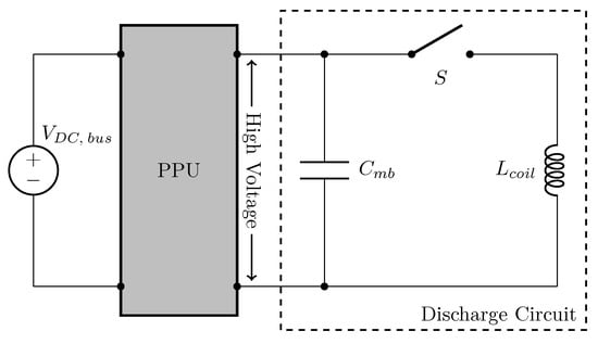
Figure 19.
Diagram illustrating the location and role of the PPU in stepping-up the voltage for an IPPT capacitor bank.
PPUs for IPPTs are still in the early stages of development when compared to those available for flight-qualified EP systems such as Hall or ion thrusters. Most IPPT PPU development to-date has centered around the EMPT and ELF thrusters. A PPU for the UM RMF-FRC thruster has been the subject of recent design efforts but has not yet been demonstrated in operation [43].
EMPT and ELF Thruster PPU
PPUs with pulse charging capabilities have been developed and tested with the EMPT [47] and the ELF thruster [58,85,86] in continuous operation. The basic circuit topology of these PPUs is shown in Figure 20. The “pulse charging” feature of these PPUs relies on the concept of basic resonant charging of a capacitor via an inductor. Each time the capacitor is discharged, current begins to flow through the charging inductor. When the switch closes, the magnetic field energy inside the inductor attempts to maintain the flow of current, pushing charge onto the capacitor bank. The result is a rapid increase in the capacitor bank voltage. Simulated voltage and current in a 1 kW version of the EMPT PPU during thruster operation at 2 kHz may be found in Ref. [47]. The primary advantages of this method are its relative simplicity, low parts count, and use of passive, rather than active, components to perform the charging process.
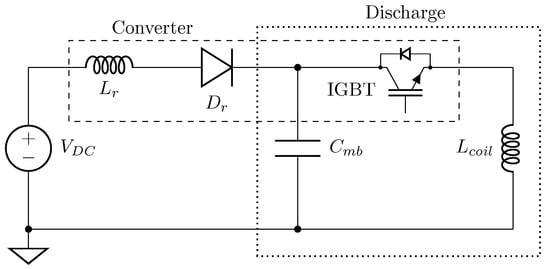
Figure 20.
Simplified circuit diagram of the pulse charging PPU used to recharge the capacitor bank of the ELF thruster during continuous operation (based on schematic from [86]).
The initial 1 kW version of the EMPT PPU [47] used pulse charging to step-up a 24 V DC input voltage to 1200 V with high efficiency. This was the first reported attempt to use a method other than a DC power supply to recharge the capacitor banks of an IPPT. It was found that a small, low voltage capacitor could be used to contain the ripple current when pulse charging to ≤5%. Early versions of the EMPT used two paralleled IGBTs for the discharge/pulsed charging switch. Later versions (also reported in Ref. [47]) used an array of smaller, higher efficiency IGBT switches. The EMPT PPU was designed to allow for thruster operation at repetition rates between 500Hz–5000Hz, with 2800 Hz identified as the optimal repetition rate for this thruster. The high repetition rate EMPT testing enabled by this PPU is believed to be the first successful IPPT operation at ≳ 1 kHz repetition rates. Thermal testing of the PPU revealed that heat was mostly generated in the pulse charging/discharge switch and that a distributed switch array was highly beneficial for PPU thermal management.
Further development of the EMPT PPU led to a redesigned 1 kW PPU and a higher power 5 kW version [85]. The 1 kW version was modular and consisted of multiple switching modules. Each of these modules tightly integrated a high current IGBT, energy storage capacitors, and driver circuitry for operating the switch. A single pulse charging circuit was shared between all of the modules, with a 100 V DC power bus feed translating to capacitor bank voltages up to 1600 V. Operation of the PPU at up to 1 MW peak pulse power and 600 W average power was reported [85]. The 1 kW PPU was also the first IPPT PPU to demonstrate stable, long-term operation. This version was reported to have been successfully operated for over discharges and 100 hrs. Steady state thermal operation in vacuum was also achieved. System longevity was due in large part to the extensive protection circuitry integrated into the PPU design, which included over-voltage, over-current, and state-of-health monitoring systems.
It should be noted that the use of the term PPU in [85] refers to the combination of the pulse charging circuit and switching modules, since here the actuation of the discharge switch is integral to the recharging of the capacitor bank. Each of the modules contained their own discharge energy storage capacitors and discharge switch, and all the modules were connected in parallel to form a distributed discharge module array. The 5 kW PPU was largely identical to the 1 kW version, with the higher power rating achieved by using six switching modules in parallel. It was found that assembling these modules in parallel required each to have independent voltage regulation and filtering as well as high voltage isolation from other modules. Independent fiber optic triggering of each module was found to be crucial. During testing, the 5 kW PPU demonstrated 3 kW continuous power operation and up to 5 MW peak pulse power [85].
The EMPT PPU architecture was extended to a 15 kW PPU design for continuous high repetition rate operation of the ELF thruster [58,85]. For this PPU, the inductive pulse charging was used to boost a 300 V DC input bus voltage to as high as 4000 V across the main capacitor bank of 1.2 F. The final charge on the bank was controlled by varying the input bus voltage and the switch on-time. The latter controlled the duration that the charging current was applied to the capacitor bank. Similar to the EMPT PPU, high power operation was achieved using multiple switching modules in parallel. It should be noted that the modules used for the 15 kW PPU, while topologically similar, were not the same as those used in the 5 kW EMPT PPU. For the 15 kW PPU, high Q-factor, film capacitors were used instead of the C0G ceramic capacitors used in the previous design, and higher power IGBTs were used for the pulse charging and discharge switches. Testing of this PPU demonstrated 15 kW continuous operation at up to 1 kHz repetition rates, with peak pulse powers as high as 55 MW [85]. An earlier version of the 15 kW ELF PPU incorporated a variable frequency pulse charging circuit to permit dynamic tuning of the repetition rate to an optimal value, which could change depending on the propellant being tested [58]. In these tests, repetition rates between 100 Hz to 1500 Hz were achieved for a nominal capacitor bank charge voltage of up to 2800 V.
“Proto-flight” versions of the ELF PPU have been developed for power levels of 1 kW and 5 kW [86]. The 1 kW variant enabled 1 J/pulse operation and was designated the “J1” PPU. The higher energy 5 kW PPU consisted of 6 J1 PPUs in parallel. This unit was designated the “J6” PPU. Circuit schematics and an assembled J6 PPU are shown in Figure 21. Having been successfully operated for more than 1 billion discharges, the ELF PPU is the most extensively tested for any IPPT. In addition to power throughput and longevity, these PPU designs have demonstrated steady thermal operation in vacuum and have been subjected to vibration, thermal, and radiated EMI testing as part of an effort to advance the readiness level of the ELF thruster system [86]. Three-axis vibration testing of the J1 and J6 PPUs found that the resonant frequencies of the two PPUs did not change in response to random vibrations and high-level sinusoidal sweeps. In addition, no mechanical failures occurred and both PPUs retained nominal functionality, indicating that the PPUs were capable of withstanding launch-like vibrational loads. Preliminary in-atmosphere thermal testing of the J6 PPU, which was attached to a temperature controlled baseplate set to 50 °C, revealed elevated component temperatures ≥70 °C after several minutes of continuous operation. Even at their peak values, however, such temperatures were well within the tolerable range of the components tested. Subsequent limited performance testing indicated that PPU performance was not compromised by operation at these increased high temperatures. Overall PPU efficiency was estimated at 88% [86].
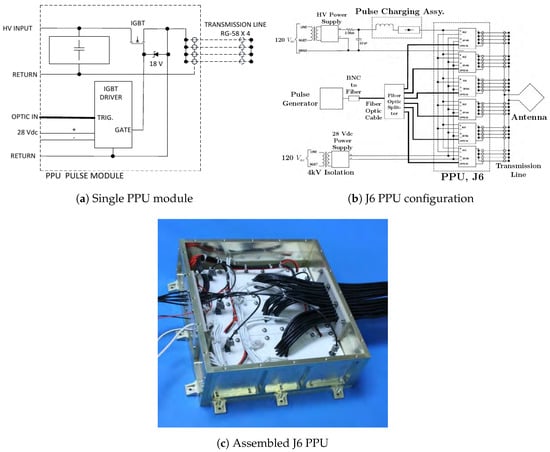
Figure 21.
The ELF J6 PPU (from [86]).
UM RMF-FRC PPU
PPUs have been developed to supply power for operation of the 30 kW UM RMF-FRC at 1 kHz repetition rates [43]. The mechanical design of this PPU is shown in Figure 22. This PPU consists of two parallel boost circuits (one for each of the RMF antenna) and a low-pass filter circuit to protect the input power source from switching transients in the boost circuits. A high speed voltage doubler configuration was selected for the boost circuit topology and provides the required voltage gain across the PPU. Switching of the PPU boost circuits is performed by a single dual configuration IGBT module, with snubber circuits included to prevent damage from switching-induced transients. The PPU was designed to be water cooled to avoid component overheating when operating at high power.
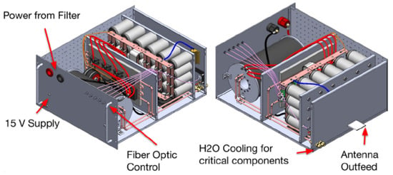
Figure 22.
Mechanical design of a single PPU to supply power to one antenna in the UM 30 kW RMF-FRC (from [43]; reproduced with permission of Electric Rocket Propulsion Society). The low-pass filter for protecting the input source from switching transients is not pictured.
4.1.2. Discharge Circuit
The conditions for efficient IPPT operation place several challenging requirements on components comprising the discharge circuit. The need to create a strong azimuthal electric field to break down the propellant and induce current in the resulting plasma requires a large current rise rate in the drive coil. In an circuit, is proportional to the voltage on the capacitor and inversely proportional to the parasitic circuit inductance. High voltages are usually required since is it often difficult to achieve the necessary rise rates solely by reducing the stray inductance. These high voltages in turn result in high peak current levels. The result is that IPPT discharge circuits often require components not only capable of handling high voltages and currents, but that can also handle extreme transients in both parameters.
Representative circuit parameters for selected IPPTs are presented in Table 2. Peak currents in the external circuit can be on the order of 1 kA to 100 kA, with current rise rates in the drive coil ≳1 kA/s. In addition, the nominal operating voltage, , can range from a few is smaller IPPTs to the tens of found in the PIT MK Va. In the balance of this section, we review the components that have been implemented in the discharge circuits of experimentally tested IPPTs, focusing primarily on the capacitor bank and discharge switch. Design considerations for the drive coil are discussed separately in Section 4.2.

Table 2.
Representative circuit parameters for selected IPPTs. (* estimated values, ** value not reported).
Discharge Circuit Topologies
The simple series discharge circuit shown schematically in Figure 14a is the most common IPPT topology. In this configuration, the initial voltage on the capacitor drives a current through the circuit once the switch is closed. The voltage and current in the system can be described using equations for a damped harmonic oscillator. Depending on the value of the damping ratio, , the waveforms may be underdamped (), critically damped (), or overdamped (), as depicted in Figure 23. For a series discharge circuit, the damping ratio is given by
where the variables are as described in Section 3.1.1. For optimal performance, the discharge should be underdamped so that the current rise rate is maximized and the current peaks while the propellant is still close to the coil face [18,61]. While simple and demonstrably effective, the basic discharge circuit has a few key drawbacks. First, since there is only a single current path, all components must be rated for the full current, voltage, , and requirements of the circuit. For IPPTs with very high per-pulse discharge energies this can make component selection very challenging, especially when attempting to incorporate solid-state electronics into the design. Second, unless the discharge is clamped after the first half cycle, the voltage on the energy storage capacitors will reverse, leading to reduced capacitor lifetimes [7,73,89]. Third, as the voltage repeatedly reverses, the current in the circuit will continue to oscillate, resistively dissipating all the remaining energy in the system.
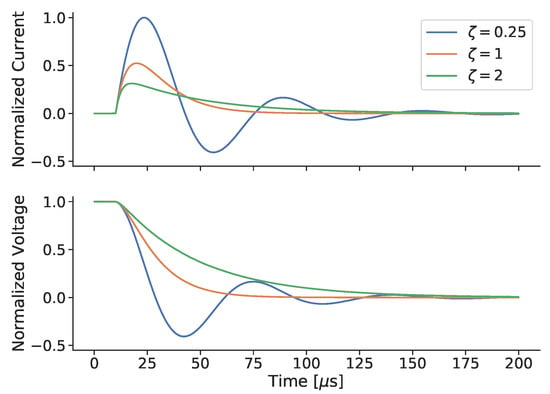
Figure 23.
Simulated underdamped, critically damped, and overdamped discharge circuit waveforms for the capacitor voltage and current.
Bernardes and Merryman [90] (B-M) proposed a variant of the basic circuit as part of a single stage induction mass driver system. A schematic of this circuit is shown in Figure 24a, with sample waveforms presented in Figure 24c. By using two capacitors of equal value in series, the B-M circuit both avoids voltage reversal on either capacitor and recaptures some of the initial energy for use in subsequent pulses. The B-M circuit was adopted by Polzin et al. [73] and tested with a redesigned version of the FARAD thruster [17,87]. This circuit featured two 20 μF capacitors, with one capacitor charged to 3160 V to yield a total stored energy of 100 J. In testing, each capacitor at the end of a pulse was charged to a little less than half of the initial charge voltage.
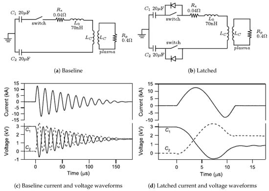
Figure 24.
Bernardes and Merryman discharge circuit schematics for (a) baseline and (b) diode-latched configurations. Current and voltage waveforms for capacitors C1 and C2 in the (c) baseline and (d) diode-latched configurations (from [7,73]).
A diode-latched version of the B-M circuit was also benchtop tested by Polzin et al. [87]. The topology of this circuit, shown in Figure 24b, adds a second switch in series with the bottom capacitor and also includes anti-parallel freewheeling diodes across both switches. These additions were intended to only allow current to flow during the first half cycle of the discharge, with current during the second half cycle being blocked by the diodes. From the capacitor voltage and current waveforms in Figure 24d, it was found that, while reduced, the second half cycle current was not completely eliminated. It was also found that this configuration resulted in capacitor retaining more of the initial stored energy while less was directed back onto . This differed from the unlatched case where the recovered energy was shared equally between the capacitors.
A novel pulse compression ring circuit topology was developed for IPPTs by Owens et al. [73,89] The pulse compression circuit, shown schematically in Figure 25a, used saturable inductors acting as magnetic switches to transform slower, low current pulses into faster, high current pulses with large , as illustrated in Figure 25b. Because the switching occurs in the lower current, slower portion of the circuit prior to pulse compression, existing solid-state IGBT switches could be used to initiate the discharge. Connecting one end of the load to the input energy storage capacitor and using a steering diode permits for the recovery of excess charge, which could be used for successive pulses. Benchtop testing of a 100 J version of the circuit demonstrated the viability of the pulse compression ring concept. Initial charge voltages of kV resulted in compressed pulses with 20 kA peak current and = 15 kA/s [89]. High energy recapture efficiency was also reported, along with successful prevention of voltage reversal on the energy storage capacitors.
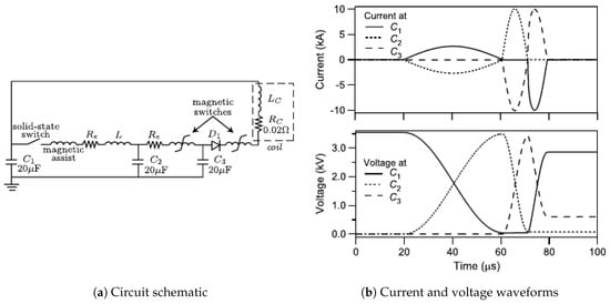
Figure 25.
Pulse compression ring (a) circuit schematic and (b) current and voltage waveforms at each of the three capacitors (Reproduced/modified from [89]; with the permission of AIP Publishing)
Inductive Energy Recapture
In an IPPT, energy stored in a capacitor is transferred into the inductor during the pulse, producing a magnetic field. Inductive energy recapture refers to the process whereby energy stored in the magnetic field that did not perform work on the plasma is redirected into the recharging the energy storage capacitors at the end of a discharge. For illustrative purposes, let us consider the case of a type discharge circuit. After the initial acceleration of the plasma, if no further action is taken charge will continue to oscillate between the capacitor and inductor until all remaining energy has been resistively dissipated in the circuit. This mode of discharge circuit operation is referred to as the “full ringdown” mode. Since most of the acceleration of the plasma occurs during the first half-cycle of the discharge, any additional flow of current beyond that time typically results in energy lost to resistive heating. This makes it desirable to interrupt the current as soon as possible after the first half cycle is complete.
To maximize the voltage recovered onto the capacitor bank and minimize the back-EMF kickback generated by interrupting the current through the inductive load, the discharge should be interrupted at either the first or second zero crossing of the current waveform. Interruption at the first crossing is referred to as “half-cycle” recapture while interruption at the second is termed “full-cycle” recapture. The former is typically more efficient than the latter because it eliminates dissipation that would occur in the second half-cycle of the discharge. Half-cycle recapture has the disadvantage, however, of causing the main bank voltage to switch polarity at the end of each discharge. If the recaptured charge is to be used on subsequent pulses, the PPU would require a dual polarity output to recharge the capacitor bank to full voltage after each half-cycle discharge. Figure 26 illustrates the general process of full-cycle inductive energy recapture using an IGBT in an discharge circuit. Here, current flows through the IGBT during the first half-cycle and returns through the anti-parallel freewheeling diode during the second half-cycle. The current through the IGBT during the second half-cycle is zero, allowing for safe turn-off of the switch.

Figure 26.
Example current waveform and IPPT discharge circuit schematic incorporating an IGBT for full-cycle inductive energy recapture.
Martin et al. [18] demonstrated half-cycle recapture by placing a fast recovery diode (FRD) in series with a thyristor switch. The FRD used in this work, however, was noted to have a slow reverse recovery time relative to the discharge cycle half period which resulted in significant energy losses during the reverse recovery period of the diode. Related testing by Toftul et al. [91] revealed that SiC PiN type FRD provided improved reverse recovery performance in benchtop testing at reduced voltages. Maximum recapture efficiency, defined as the fraction of the initial stored energy recovered onto the capacitor bank, was ≈20% when using Si FRDs but in the best case increased to ≈30% with SiC FRD. Data indicated that the recapture efficiency improved as the nominal charge voltage was increased, but results were only reported for voltages up to 550 due to concerns of damaging the SCR switch used to trigger the discharge circuit.
Poylio et al. [92] reported efforts to achieve full cycle recapture in an discharge circuit using a stack of five gate turn-off (GTO) thyristor switches. Turn-off pulses were applied to the switches at both the first and second zero crossings of the current to halt flow through the thyristors during the second half cycle of the discharge. The control pulses were timed such that the peak control pulse current corresponded with the zero crossing of interest. Peak current in the turn-off control pulses was about 900 in both cases. It was found that current continued to flow through the GTO thyristors well after the turn-off control signal was received, regardless of whether it was applied at the first or second zero crossing.
Martin [72] compared simulated IPPT efficiencies for an discharge topology operating in full ringdown, half-cycle, and full-cycle recapture modes. It was found that peak efficiencies for the recapture modes were often >30% higher than the full ringdown case. Interestingly, the difference in peak efficiency between the half-cycle and full-cycle recapture cases was only found to be a few percent. The potential reduction in PPU complexity in the full-cycle case may compensate for this slight decrease in efficiency.
Most of the discussion of energy recapture has centered around the basic series discharge circuit. Here, interruption of the current is required to recover voltage onto the capacitor bank. In contrast, the B-M circuit tested by Polzin et al. [17,73,87] naturally achieved energy recapture without the need to stop the flow of current. The efficiency of the recapture in this circuit is not optimal since the current is allowed to oscillate and resistively dissipate energy for many cycles. The latched B-M circuit tested by Polzin et al. [73] sought to improve the recapture efficiency of the B-M circuit by implementing half-cycle recapture using diodes. Current and voltage waveforms from a benchtop circuit indicated that, although reduced, current was not fully shut off at the end of the first half cycle. While no explanation was given in [73], it is suspected that slower than required diode reverse recovery may have been the cause.
Switches
The switch connecting the energy storage capacitor to the drive coil must be capable of holding off the nominal charging voltage, conducting currents up to several , and surviving extremely large transient and values. The PIT MK V and MK Va employed a series-parallel array of 18 spark gaps designed to switch peak currents of ( per switch) at rise rates on the order of 270 kA/s (≈30 kA/s per switch) [3,9]. Nominal stand-off voltages for these switches was . Simultaneous switch firing was found to be a major challenge when paralleling spark gaps in this configuration. The switches had to all fire within a window of 5 ns [3]. It was also noted that, while sufficient for single shot testing, spark gap switches were ill-suited for extended duration, long life operation and solid-state switching would ultimately be required.
Future work to develop the PIT MK VI identified several additional disadvantages associated with the use of spark gap switches. Hrbud et al. [9] noted that the nominal erosion rate of the spark gap electrodes was too high to support the large number of pulses required for an interplanetary mission. In addition, electrode erosion would change the spark gap electrode separation over time, which would likely alter the operational characteristics of the gaps even before switch failure occurred. Other potential issues included challenges with high repetition rate (≳ 10 Hz) operation, susceptibility of the gap insulation to radiation damage, and difficulties in maintaining the appropriate gas pressure inside the switch while operating in a space environment for an extended period of time. These issues, combined with the strict timing requirements noted previously, led to an investigation into the use of solid-state switches. Development of the PIT MK VI and MK VII by Poylio et al. [92] led to testing of stacks of pulsed power thyristors as spark gap replacements. To provide switching capabilities similar to spark gaps, it was estimated that the thyristor stacks should have breakdown voltages , support peak currents and current rise rates , and close in times no slower than ≈ 300 ns. A stack of five ABB Model 5SHX 14H450X thyristors was found to meet or exceed these requirements, providing , , , and . Attempts to achieve inductive energy recapture by shutting off these switches during the second half cycle of the discharge were unsuccessful, however. In addition, it was noted that testing of the thyristor stacks would be necessary to confirm switch lifetime sufficient to meet mission requirements.
Solid-state switches have also been implemented on a smaller IPPT by Martin et al. [18]. In this work, a single thyristor (Dynex PT85QWx45) and fast recovery diode (FRD) (Dynex DSF21545SV) were used to control discharge currents up to . The maximum charge voltage was and the current rise rate was estimated to be . It is worth noting that these values were well within the capabilities of the thyristor, which was rated to , , and . Triggering of the thyristor at repetition rates of up to 20 Hz was successfully demonstrated. The series FRD in this work was implemented to perform inductive energy recapture. By stopping the reversal of the discharge current, the capacitor bank is clamped at some negative voltage and a portion of the initial stored energy is retained. The Dynex Si FRD had a reverse recovery time of ≈7 μs, which was found to be somewhat slow given the ≈20 μs half-cycle period. Nonetheless, some degree of current blocking was observed. A related effort compared the performance of an ABB Si FRD and SiC Schottky diodes in the same circuit [91]. In that test, the data show that the Si diode took 5–6 times longer to halt current flow relative to the SiC diode.
For high repetition rate thrusters, solid-state switching is the only practical option to reduce the time between pulses. Fortunately, the lower discharge energies-per-pulse characteristic of high repetition rate operation reduce the voltage, current, , and requirements on the switches. The EMPT discharge circuit used two high-speed IGBT switches from manufacturer Semikron® rated up to 9 kA of peak current. Later testing used a distributed array of smaller, higher efficiency IGBTs made by IXYS®. The faster switching times of both IGBT models enabled the EMPT to achieve the first reported multi-pulse operation of an IPPT at multi-kHz repetition rates [47]. Paralleling of multiple high power IGBTs was found to enable peak discharge currents up to 20 kA in the 30 kW ELF thruster [85].
Capacitors
The energy storage capacitor must be able to rapidly source the large currents required by the discharge while also withstanding the full charging voltage for many cycles. To avoid excessive Ohmic heating, the bank equivalent series resistance (ESR) must be as small as possible. In addition, it is also desirable that the equivalent series inductance (ESL) be low to help minimize the circuit stray inductance. Moreover, the capacitor must be able to handle the the polarity reversal of the applied voltage during the discharge. Finally, the capacitor must survive exposure to the vacuum environment.
While many different types of capacitors exist, film and ceramic/mica capacitors appear to be best suited to the demanding requirements of IPPT operation. Film capacitors are a type of non-polarized capacitor in which the dielectric material is a thin plastic film. Modern film capacitors typically have low ESR and ESL, which results in a low dissipation factor and makes them well suited for high frequency applications involving high surge currents. In addition, film capacitors that can withstand several or more are readily available. In the case of very high voltages (≳ 10 kV) the capacitors may be pressurized and oil filled to prevent breakdown of the capacitor dielectric.
Most IPPTs tested have used film type capacitors [3,16,18,58]. The PIT MK Va used 18 separate 2 F oil-filled, pressurized film capacitors charged to as much as 16 kV in a Marx bank configuration. The total capacitor bank had a nominal charge voltage of up to 32 kV and possessed an effective capacitance of 9 F. Both the FARAD thruster [73] and the NASA-Marshall 27 cm diameter IPPT [18] used oil-filled pressurized film capacitors, with 20 F capacitance in the former and 10 F capacitance in the latter.
Film capacitors designed for snubber applications are particularly well suited for use as IPPT bank capacitors, since they are typically designed for operation at very high and rates. Paralleled arrays of WIMA™ FKP and/or MKP series snubber film capacitors were used for the energy storage banks in the EMPT [47] and ELF thruster [58]. Typical bank capacitance in these thrusters was roughly 24 for the EMPT and for the ELF thruster. For reference, the FKP snubber capacitors are reported to have a dissipation factor of at 10 kHz and a maximum pulse rise time of 5000 V/s at 3 kV.
To date, the EMPT and ELF thruster are the only known IPPTs to have used a distributed array of ceramic capacitors for the main discharge bank [47,85,88]. This design choice was motivated largely by the need for improved thermal management of the capacitor bank during continuous operation at high power for extended duration. A distributed capacitor array has more surface area for heat extraction, making heat sinking more effective. The parallel connection of many capacitors also tends to reduce the net ESR and ESL of the bank, assuming the connections themselves do not add excessive stray resistance or inductance. Reducing the ESR has the added benefit of decreasing resistive heat generation, which in turn reduces the load on the cooling system. Ceramic capacitors can possess quality factors, defined as the ratio of energy stored to energy dissipated, which are very large and result in greater circuit efficiency and lower heat generation. Initial thermal testing of the EMPT at 1 kW revealed that the heat loading to the ceramic capacitors was small, with the bank temperature rising only a few °C over hrs. Similar testing of the ELF thruster [88] found the bank only reached ≈45 °C after nine minutes of operation at . This value was well below the 175 °C rated temperature of the capacitors and is indicative of the effectiveness of the distributed bank approach for thermal management.
4.2. Drive Coil
In an open magnetic flux IPPT, the drive coil couples energy into the propellant, leading to acceleration of the gas. While the coil or coils also couple energy into the plasma in a closed magnetic flux IPPT, most work on coil optimization has been performed for open flux devices because the acceleration process in these devices is extremely sensitive to the drive coil parameters. The drive coil is characterized by an electrical parameter, the inductance, which is subject to competing constraints. The inductance should be high relative to the stray inductance in the circuit such that a substantial fraction of the charge voltage on the capacitor is actually applied across the coil, but it must not be so high as to limit the current rise rate, , of the circuit to levels below which ionization and acceleration suffer. However the current rise rate cannot be too fast or there is a risk of damage to solid-state devices such as switches and diodes. The size of the coil, and hence its inductance, is also influenced by other considerations. There are practical limits on how big or how small a coil can be fabricated. It is also important to design the device so that the propellant gas injected before the discharge covers the coil face but does not migrate beyond the coupling length of the coil in the interval between successive discharges.
The PIT MK V and MK Va coil (which was really the same coil, see Figure 2) consisted of nine primitive coil circuits clocked around a circle at 20° increments. Each circuit is electrically independent of the others, but all are discharged at the same time. Each primitive circuit was comprised of two capacitor banks (capacitor and switch) arranged in a Marx-bank configuration, with the spiral coil segments broken into a series of four quarter-turn spiral coil segments. The quarter-turns are situated in grooves in an insulating coil form such that they alternate spiralling inward on the front side of the form and outward on the back side. This arrangement had very low parasitic inductance leading to a very high current rise rate. Summing all the currents for the entire coil, the radial current components cancel yielding an almost purely azimuthal surface current. At the edge of the MK V coil, the segments had a greater pitch to compensate for a weaker field due to field fringing.
Other IPPTs have used coils with multiple turns wound in the shape of an Archimedes spiral [13,16,17,19] with the path of a coil lead, , expressed in polar coordinates as:
where and are the inner and outer coil radii and is the angle in radians. Multiple leads in parallel are used to reduce the total inductance and produce a more uniform current density. An illustration of this coil geometry is shown in Figure 27 for a notional coil with six two-turn leads and inner and outer coil radii of 5 cm and 15 cm, respectively. Each lead completes one outward counter-clockwise spiral on the front of the coil form, then threads under the form and completes one inward counter-clockwise spiral. As with the PIT MK V coil, radial components of the current in the front and back leads cancel while the azimuthal components add to produce a uniform azimuthal surface current. Coils are typically wound so that the terminations are physically close to one another to reduce the stray inductance in the circuit, although it is not always practical to do so.
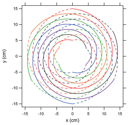
Figure 27.
Illustration of a two-turn Archimedes spiral coil with six parallel leads clocked at 60° intervals, indicated by the colors red, orange, green, blue, purple, black. Each lead completes one outward counter-clockwise spiral on the front surface (solid line) and then one inward counter-clockwise spiral on the back surface (dashed line) to return to the initial starting point.
A recent proposal by Raines [93] for improving the overall coupling between the coil and the plasma in an IPPT, particularly on the inner and outer edges of the drive coil, is to use a coil based on the Halbach array geometry, shaping the magnetic field in a more optimal way. Such a field configuration might also reduce parasitic losses in the device by reducing the field strength on the back side of the coil. Computational modeling of an electromagnet designed to mimic a Halbach array indicated that it is possible to fabricate a drive coil to create such a field configuration. This coil, shown in Figure 28a, has a standoff between the front and back faces with additional windings in the axial direction on both the inner and outer edges of the coil as well as a permeable core in the center of the coil. The resulting flux contours (calculated using finite element magnetic modeling) are shown in Figure 28b. How the inclusion of a permeable core in a pulsed coil would work in practice, or how it could be dispensed with altogether, is a subject for further research.
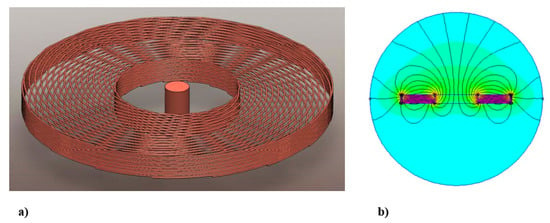
Figure 28.
(a) A proposed Halbach array-based design for a drive coil and (b) computed flux contours for the proposed configuration (from [93]; reproduced with permission of the author).
4.3. Propellant Management and Injection
The propellant management system of an IPPT consists of tankage, propellant feed lines, and a valve for propellant injection. Most propellants do not require special tank designs, cryogenic storage, or novel materials for the tanks or feed lines. Likewise, space-rated components that could be incorporated to monitor the gas pressure in the tanks is fairly well developed. The propellant valve, on the other hand, may or may not be a limiting component in the system, depending on how the thruster is operated.
A fast, low leakage pulse valve is required for an IPPT operating in either single pulse mode or at a slow repetition rate, the latter being where the gas injection timescale is much shorter than the period between pulses of the thruster. Most high discharge energy-per-pulse tests to date have been in single pulse mode, but the results, scaling, and requirements can be applied equally to the slow repetition rate mode. For single-pulse operation, a plenum is typically charged to a certain pressure, controlling the mass bit for a pulse. The valve must open rapidly, remain open a short period of time, and close equally rapidly so as to maximize the amount of gas injected from the plenum into the thruster by minimizing the amount that either has a chance to escape to vacuum or that has not yet entered the thruster before the electrical pulse through the coil is initiated. For this discussion, being ‘in the thruster’ means that the propellant is within the electromagnetic coupling distance of the coil. The entire valve actuation process occurs on the order of 1 ms, with the opening and closing occurring much faster. In addition, the valve must maintain a relatively low leak rate to ensure propellant does not excessively drain from the system between pulses. In the PIT MK Va, a solenoid valve based on a speaker design was used, with rapid opening accomplished by pulsing high current driven by a separate 10–15 J capacitor through the valve coil windings and rapid closure achieved using a stiff metallic diaphragm as a closing spring connected to the moving seal [10]. It has been estimated that a valve of this type might have to survive – pulses for a realistic mission [3,94], but a life test of this design only demonstrated up to ∼ cycles [3]. In addition, no quantification of the leak rate for this valve as a function of the number of pulses is available in the literature.
As an alternative to the solenoid valve design, a piezoelectric valve with a low leakage rate and a rapid opening and closing time (∼100 s for each) was fabricated and tested [95,96]. The current and power required for this valve are several orders of magnitude lower than that for a solenoid valve since piezoelectric crystals are high impedance loads that operate at high-voltage and low-current. The opening of the valve is scalable with the applied voltage, providing a new means by which the gas injection rate can be controlled. The overall travel range of the valve plunger is roughly 10 m. This valve design demonstrated operation up to 3×10 cycles, but excessive leakage above 10 sccs of helium was observed after ∼2×10 cycles. The Inconel 625 material of the valve poppet exhibited wear and material transfer at the sealing surface on the seat, providing leak paths for propellant to escape. Fabricating the poppet with harder materials could mitigate this effect in future designs and deliver low leakage for a greater number of cycles.
Gas injection in planar IPPTs has typically been accomplished in pulsed mode. The PIT and other planar variants have typically employed a central injector or pylon design with the gas injected back towards the face of the thruster, axially stagnating where the pylon meets the thruster coil and expanding radially outward to cover the coil face [3,13,18]. The electrical pulse through the coil is initiated just as the gas completely covers the coil face. An issue with this method is the presence of the gas injection pylon in the downstream flow as the propellant accelerates away from the coil and the bombardment and sputtering that can occur when the high speed plasma inpacts the pylon head. CTP-IPPTs performed best with gas injected against the conical coil face with azimuthal swirl imparted to the propellant [4]. Pulsed gas injection was not attempted in CTP-IPPT testing, but it is expected that there would be significant latent propellant remaining in the feed lines when the thruster was pulsed, resulting in a low propellant use efficiency.
If the thruster repetition rate is high enough such that the period between pulses is roughly equal to the gas injection timescale, then the valve may be left open, providing continuous propellant injection. In this case, gas enters the thruster at a sonic, gasdynamic speed (typically on the order of 100 m/s), filling the thruster just as the electrical circuit is recharged and ready to pulse. No excess injected propellant has the opportunity to escape before the pulse is initiated, quickly accelerating the ionized gas out of the thruster and making room for the injection of propellant for the next pulse. This significantly reduces the requirements on the valve by lowering the overall number of required valve cycles and negating the fast valve opening and closing requirements. While the valves must still possess a low leakage rate, the sealing surfaces do not experience the same level of wear and abuse as those valves needed for single-pulse operation. Flow rates in these systems can be controlled with a mass flow controller, permitting accurate control of the injected mass per pulse.
Thrusters operating at a lower discharge-energy-per-pulse have already demonstrated repetition rates that permit the use of a continuous flow gas injection scheme. The ELF thruster demonstrated this at discharge energies of 10 s of J/pulse with propellant continuously fed from the back of the thruster into the discharge cavity [51].
The IPPT family of thrusters possess no electrodes in contact with the plasma, so a wide range of propellants are available for use. As noted in the present review, various IPPTs have been tested using ammonia (NH), simulated hydrazine (N + 4NH), hydrogen (H), helium (He), nitrogen (N), carbon dioxide (CO), argon (Ar), xenon (Xe), and water (HO). For some of these propellants, the same propellant management system could be employed, resulting in a propulsion system that could be refilled using various propellants that could be derived from in situ resources at different destinations. In addition, some propellants may also be used in chemical thrusters, with the same propellant tankage feeding those thrusters and an IPPT. Propellants such as hydrazine could present thermal problems through the release of potentially significant amounts of additional heat through dissociation. This additional heat would need to be handled within an IPPT thermal management system [3]. While the same injection system may be used for multiple gaseous propellants, operation on liquid propellants requires a different, more specialized propellant injection system. Water is a particular challenge because it must be pre-heated before injection so it will not flash-freeze as it is injected into the vacuum environment [88].
4.4. Preionization
Initiating an IPPT discharge is difficult because all coupling between the external circuit and the propellant occurs through electromagnetic fields. Since the external circuit is separate from the plasma current loop, current will still flow in the former even if the gas does not ionize and form a plasma. Any delay in the formation of the plasma will result in energy being dissipated in the external circuit without performing useful work on the propellent.
Preionization in the context of an IPPT refers to a strategy to partially or fully ionize the propellant prior to the initiation of the main discharge pulse. This can be done to minimize the time between external circuit discharge initiation and electromagnetic coupling with the plasma current. It can also be done to reduce the voltage and current in the external circuit needed to fully ionize and accelerate the propellant, reducing the corresponding requirements on capacitor and switch voltage holdoff, current conduction, and switching speed.
Preionization has been tested in different thrusters with varying degrees of success. Those tested in planar IPPTs are summarized in Ref. [7]. A 30-cm planar IPPT attempted four separate preionization methods [12]: (1) a 440 nF capacitor discharged through the drive coil, (2) a 40 nF capacitor discharged through the drive coil, (3) a 440 nF capacitor discharged through a 30 cm circular wire loop 5 cm downstream from the drive coil, and (4) a 440 nF capacitor discharged through a mirrored copy of the drive coil located 4 cm downstream of the actual drive coil. For the case of pulsed propellant injection, it was found that preionization methods 1 and 2 did not increase performance over the case where preionization was not implemented. It was concluded that since the preionization discharge was driven through the same coil responsible for accelerating the gas, the preionized propellant was subjected to the same acceleration forces and began to move away from the coil face, reducing the electromagnetic coupling efficiency during the main pulse. There was a slight improvement to and when preionization method 3 was employed. Preionization method 4, however, was found to produce the best results. The efficacy of this method was thought to be the result of the mirror coil axially compressing the preionization plasma back against the drive coil, which led to an improvement in electromagnetic coupling since the propellant was pushed closer to the acceleration coil. However, this is somewhat impractical in practice since the accelerated plasma would directly impact the forward coil, sputtering it rapidly.
Work by Polzin [16] demonstrated preionization-assisted breakdown of propellants at discharge energies and voltages well below the levels that could ionize the gas without preionization. In that experiment operating with a neutral gas backfill, the plasma from a helicon discharge along the thruster centerline was directed with an applied magnetic field to the thruster face, providing the seed preionization plasma. Additional plasma ionization and current sheet formation would not occur during the discharge through the external circuit if the helicon discharge was not operating or if the magnetic field was adjusted such that the plasma was not directed to the coil face. A more recent implementation of the FARAD concept [17,87] employed a vector-inversion generator (VIG) preionization source. This was effective in producing a preionized plasma, but it also radiated significant electrical noise as the VIG operated at a ‘slower’ base frequency of 80–100 kHz with a much higher frequency ‘fast’ modulation superimposed on the main signal. At the design point for that version of FARAD, the main pulse through the acceleration coil was able to ionize the propellant without preionization, and no attempt was made in that work to further quantify the usefulness of VIG preionization. The VIG concept also introduced electrodes in direct contact with the plasma, partially negating the advantage of an electrodeless thruster.
Several other preionization methods have been implemented in IPPTs at various energy levels. In high discharge energy FRCs, the first half-cycle of the discharge in the theta pinch configuration was often used to produce a preionized plasma that would ‘freeze’ an externally applied bias field into the plasma prior to the the production of the compact toroid plasma configuration during the current and field reversal of the second half-cycle of the discharge [8]. At lower discharge energies, Martin et al. [18] in a planar IPPT and Hallock et al. [19,71] in a CTP-IPPT opted for a Paschen-type high voltage DC breakdown preionization method, with electrodes located at the center and outer edge of the thruster face. While effective and relatively simple, it should be noted that this method also introduces electrodes in direct contact with the plasma, which may limit the types of propellants that can be used. CTP-IPPT experiments also included attempts to use a microwave-driven electron cyclotron resonance (ECR) discharge as a preionization source, and while successful in ionizing the gas, this method was not further pursued due to logistical issues with integration in the test setup. RMF-FRC test articles typically possess preionization, as described in Section 2.2.2. For example, a number of preionization approaches were tested for the ELF thruster [51], with a DC Paschen breakdown between two coaxial electrodes being chosen for early experiments and a small RF-driven inductive coil used in later experiments [88].
4.5. Cooling
Resistive dissipation of energy in the external circuit and inefficiencies in the PPU may result in high heating loads that could become an issue for thrusters operating at high average power levels and repetition rates. In addition, direct radiative heating of the coil from the plasma may also deposit up to 10% of the energy per pulse into the acceleration coil [3], compounding the already-challenging thermal issues. As the average power to the thruster increases, either because of an increase in the discharge energy per pulse or the number of pulses per second, the thermal issues only become more daunting.
While very little has been done to systematically address the thermal issues that will arise in flight IPPTs, there have been designs and laboratory experiments that recognized the inherent thermal issues of higher-power throughput operation and incorporated cooling schemes. While it was never fabricated or tested, the conceptual design of the PIT MK VII considered long-duration continuous operation that would require the use of fluid cooling for the coil, switches, pulsed gas valve, and propellant injection pylon [92]. A high power 15 kW PPU designed to drive the ELF thruster coils was thermally coupled to a water-cooled plate and tested in the lab environment. Operating at a frequency of 200 kHz, the setup reached thermal steady state in a couple minutes. The IGBTs in the circuit were the hottest components, reaching temperatures of 70 °C [88]. Most recently, the 30 kW UM RMF-FRC was designed to have water cooled bias coils and PPU electronics [43].
4.6. External Fields
Externally applied fields have been used in IPPTs for a number of different purposes. When used in planar IPPTs, applied fields have primarily been associated with attempts to incorporate preionization. The applied field in the FARAD device was necessary for the helicon discharge that produced the preionized plasma [15]. In that setup, the magnetic field was produced by electromagnets, which were configured such that the preionized plasma created in a region of axially directed field was turned by the field to propagate radially-outward over the face of the acceleration coil. In the CTP-IPPT, permanent magnets were configured to produce local pockets of high magnetic field at the face of the conical coil where preionization through ECR energy deposition into the gas could occur [19]. In both cases, the applied field was not required for acceleration of the plasma, but it was noted that an applied field in the proper direction could result in an additional Lorentz body force component in the axial direction, augmenting thrust [16]. There is the possibility that the applied field will resist motion of the plasma. However, the magnetic field produced during the current pulse through the acceleration coil should overwhelm any DC applied field as the strength of the former is typically greater by an order of magnitude or more. Also, the strong fields produced during the acceleration pulse may, over time, alter the magnetic properties of permanent magnets, making their use problematic.
Several FRC thrusters use an applied field, and in these thrusters the applied field may play a major role in the plasma acceleration process. The RMF FRC thruster variants (e.g., [42,43]) drive an azimuthal current in the diverging portion of a magnetic nozzle. The interaction of the current and the magnetic field produces a component of the Lorentz body force in the axial direction, yielding thrust. In pulsed theta-pinch FRCs with applied bias fields, (e.g., [8,36]) the applied field is frozen into the plasma during the first half cycle of the theta pinch discharge. As the discharge current reverses during the second half-cycle, the pinching field at the ends of the device trap the frozen field, which separates from the rest of the applied field and becomes part of the embedded magnetic field that comprises the plasmoid structure.
5. Advancement Paths: Modeling
Improvements in IPPT modeling techniques may be of great benefit to increasing performance, scaling operation to different power regimes, and understanding how different propellants affect thruster performance. Important IPPT processes that are deserving of renewed attention are current sheet formation and stability, plasmoid formation and acceleration, and plasma chemistry associated with non-traditional, molecular propellants. These processes and possible modeling advancement paths are described in this section.
5.1. Formation Physics
Formation refers to the process by which propellant ionizes and self-organizes into a coherent plasma structure prior to acceleration. The initial propellant state can be either a neutral gas or, in the case of low pulse energies (<100 J), a partially preionized plasma. Formation can be closely coupled to the acceleration mechanism (e.g., current sheet formation in an IPPT) or independent of the acceleration mechanism (e.g., inductive FRC acceleration). The formation time must be slow compared to the characteristic ionization time and fast compared to both the acceleration time and growth time for large-scale plasma instabilities. Reliance on such a strongly non-equilibrium process represents a fundamental difference between pulsed and steady-state electric propulsion concepts. It is therefore critical to understand the physics of formation to ensure that each pulse efficiently uses both the injected propellant and the applied electricity. Insights into this process could guide the design of more effective propellant injection and preionization systems. Furthermore, the inclusion of formation physics in plasma-circuit models could play a critical role in understanding and optimizing thruster performance across the power spectrum.
5.1.1. IPPT Current Sheet Formation
While there have been significant efforts to model the plasma acceleration process, there has been very little work on including the gas breakdown and current sheet formation processes in this modeling. While it may be the case that the timescale for breakdown and ionization is short relative to the acceleration timescale, and that the energy invested in ionizing the propellant is small relative to other energy sinks [10], there will certainly be differences in both as a function of propellant type. For IPPTs that claim the ability to process many different types of propellant, including those derived from in situ resources, understanding and quantifying these differences and the effects they have on the overall performance of the thruster could be important when planning a mission and selecting the propellants that will permit the mission to close.
The following important outstanding issues related to current sheet formation present themselves and candidates for future modeling efforts.
Key Physics and Requirements for Current Sheet Formation
Gas breakdown and current sheet formation must occur on sub-microsecond timescales. This creates a highly transient process where neutral propellant gas is rapidly reorganized into a high-density magnetized plasma. The frequency and magnitude of the azimuthal electric field induced by the transient coil current and the level of the gas pressure are all known to play critical roles in the initial breakdown of the neutral gas [97,98]. Less is known about how the preionization system influences gas breakdown requirements. It is desired that a high-conductivity, uniform current sheet forms on the coil face to maximize inductive energy transfer. Similarly, a secondary (‘crowbar’) plasma discharge formed from residual gas after the first half-cycle should be avoided. The ability to investigate and predict these important aspects of current sheet formation is not presently possible with existing IPPT models. One possible advancement path towards this goal would be to adapt existing Z-pinch current sheet formation models to include inductive current drive in planar geometries.
Current Sheet Formation Scaling to Lower Energy per Pulse
At lower pulse energies, less energy is available to ionize the propellant, resulting in a lower-density plasma and a generally weaker current sheet. This opens the possibility for other physical processes, such as resistive diffusion of the induced magnetic field, thermal expansion of the plasma, and neutral gas migration, dominate the plasma dynamics. Experiments show that preionization of the propellant prior to the main inductive pulse can be critical to current sheet formation at low pulse energies [7]. However, it remains to be determined whether or not low energy-per-pulse IPPTs can achieve the same performance as their high energy-per-pulse predecessors. The influence of preionization physics on current sheet formation is even more critical in low discharge energy regimes where ionization may not occur at all without preionization.
Propellant Mass and Energy Loss during Current Sheet Formation
It is imperative that each thruster pulse efficiently uses the propellant mass and electrical energy. Propellant use requires the creation of a uniform current sheet that is capable of entraining a significant percentage of injected gas. Energy use requires formation of the current sheet near the coil face, with most gas entrainment occurring before the current sheet is moving quickly to minimize gas entrainment loss processes and other inelastic collisional processes such as ionization. These effects will be strongly influenced by a number of factors including the thruster geometry, gas distribution prior to the pulse, discharge current magnitude and rise rate, and propellant type. Extension of the equation of state model by Polzin et al. [64] to include preionization and early breakdown phenomenon could help understand mass and energy loss mechanisms during this period. Furthermore, use of this model could allow these effects to be directly coupled to the circuit model for thruster performance.
Current Sheet Stability on Formation and Acceleration Timescales
It is also important that the current sheet maintains its structure throughout the formation, acceleration, and gas entrainment processes. The development of large scale instabilities could lead to plasma filamentation, reducing the inductive coupling and making the current sheet more permeable to both encountered gas and the magnetic field driving acceleration. Understanding how strong plasma gradients and magnetic field fringing might influence instability growth could help mitigate deleterious effects. Existing two-fluid models for gradient driven instabilities could be adapted to a “typical” current sheet structure to examine how the growth rate of dominant modes compares to the current rise time.
5.1.2. FRC Formation
Laboratory experiments consistently show that FRC plasmoid formation is highly dependent on the characteristics of the vacuum magnetic field, method of gas injection, and the preionization system used [20]. From ∼1 J propulsion FRCs [58] to ∼10 MJ fusion FRCs [24], the importance of effective preionization was observed. Modeling of the FRC formation process has focused mainly on understanding how an open-flux uniform magnetic field plasma evolves towards a closed-flux compact toroid in the presence of transient external fields, generated either by a theta-pinch [99] or using a RMF [100]. Despite exerting significant control over the properties of the resulting FRC, a detailed model of FRC formation including neutral gas injection and ionization physics has not been published in the literature.
We highlight two important questions that should be addressed to improve the modeling of FRC formation.
Key Physics and Requirements for FRC formation at Low Discharge Energy
Spacecraft system constraints generally limit FRC formation in IPPTs to many orders of magnitude lower energy compared to compact fusion applications. While the available data are limited, research on low-energy (∼100 J) FRC thrusters shows that the resulting plasmoid properties vary significantly with the method of formation. This is perhaps best demonstrated by comparing downstream Langmuir probe results from a theta-pinch-generated FRC [30] and a RMF-generated FRC [42]. The width of the time-dependent probe traces and characteristic velocities suggest that the length of the ejected theta-pinch-generated FRC was approximately equal to the thruster length. A similar analysis for the RMF-generated FRC indicates that the ejected plasmoid had a length up to three or four times the thruster length, which may indicate that a closed-flux plasmoid was not actually formed in this case. This disparity suggests that not all formation schemes may be successful at forming a plasmoid at low discharge energy, and the processes governing this formation may be significantly different depending on the method by which the FRC was produced. Insight into the required conditions for FRC creation at low energies could be greatly improved using a two-dimensional plasma fluid model or kinetic code that incorporates both neutral gas ionization and time-dependent boundary conditions to model the fields applied to the gas during FRC formation.
Propellant Mass and Energy Losses During FRC Formation
In an IPPT, a significant percentage of injected propellant mass must have appreciable kinetic energy imparted to it for high efficiency operation. It is therefore important to understand the ways in which the propellant mass might not be accelerated and the various energy loss mechanisms that might dissipate energy during each FRC formation phase. Modeling these dynamics is a significant undertaking and will likely require the combination of a time-dependent plasma fluid model, similar to that described above, with a collisional-radiative description and empirical models for turbulent transport. Advances towards this goal will also require extensive experimentation to support empirical model development and provide validation data.
5.2. Acceleration Physics
Although the acceleration physics in IPPTs has been the subject of a number of studies, there are aspects of this process that remain poorly understood. Most notably, there are multiple mechanisms by which the external energy of the driving circuit can be converted into the directed kinetic energy of the propellant. These include electromagnetic acceleration via self-field interaction, Lorentz body force acceleration arising from an interaction between the induced plasma current and an applied magnetic field, and thermal acceleration driven by pressure gradients in the plasma that are produced by Ohmic heating and electromagnetic compression of the plasma. While all three mechanisms may have a role in IPPT propellant acceleration, it is often not clear which is dominant in a particular test apparatus. This ambiguity is reflected in the relative lack of validated models and scaling laws for many IPPT concepts. In fact, the only thruster that has well-understood performance scaling strategies is the planar IPPT variant. As a practical result, there are relatively few established design strategies for how to improve performance in the other IPPT variants, and the theoretical upper bound on performance in these thrusters is not well-known. Future acceleration physics studies should focus on developing models at multiple levels of fidelity to capture and determine the partitioning between different acceleration mechanisms, with the end goal to determine and optimize the dominant mechanisms that efficiently convert input electrical energy into thrust.
5.2.1. Identification and Scaling of Dominant Acceleration Mechanisms
Thruster operating regimes exist where certain forces are able to accelerate plasma propellant more efficiently than others. A notable example of this is the dominance of self-field acceleration above a certain threshold current in magnetoplasmadynamic thrusters [101]. Likewise, IPPT models need to contain proper modeling and scaling of the different possible acceleration mechanisms. The dominant acceleration mechanism will likely depend on several different factors including acceleration coil geometry, current rise time and amplitude, and the internal plasma pressure and energy density. It is known that radial compression and heating of a CTP-IPPT (either in open or closed magnetic flux operation) increases with decreasing cone angle [4,72]. In principle, a critical cone angle should exist where the dominant axial acceleration mechanism transitions from direct electromagnetic acceleration to a pressure-driven acceleration. However, a detailed understanding of the specific processes by which radial electromagnetic compression is ultimately converted to directed kinetic energy via plasma heating and axial acceleration does not yet exist. In certain configurations, further complications arise due to the presence of applied magnetic fields and passive magnetic flux conserving components. These alter the overall magnetic field structure in an accelerator and can affect the current density profiles in and around the plasma, which in turn can alter the Lorentz body force density, plasma compression, and heating profile. Insight into the dominant acceleration mechanisms for different IPPT geometries and configurations could be obtained by modifying existing two-dimensional MHD models to include applied magnetic fields and conducting boundary conditions. We note this effort would greatly benefit from extensive experimental validation. For example, new methods [102] for measuring the thrust component generated via a particular acceleration mechanism may potentially be applied in future IPPT experimental investigations, with those data supporting the refinement of modeling efforts.
5.2.2. Influence of Changing Plasma Geometry on Inductive Acceleration
Electromagnetic acceleration in IPPTs depends largely on the relative geometries and distance between the plasma and accelerating coil. In an equivalent circuit view of the problem, this is largely captured in the inductance of the plasma and the coil and the changing mutual inductance between the two. Circuit modeling of planar IPPTs [61] was successful in developing and employing semi-empirical expressions for M based on calculations and experimental measurements using a simulated plasma load. Solid conductive slugs have been used to experimentally model mutual inductance in CTP-IPPTs [71]; however, radial plasma compression complicates this approach by adding an additional degree of freedom to the problem. To overcome this challenge, numerical solvers have been used to obtain expressions for the mutual inductance as the plasma moved in two-dimensions in a CTP-IPPT [72] and in FRC thrusters [54,76]. Only two of these approaches have attempted to also include the effects of changing plasma geometry, in addition to separation distance, on the mutual inductance profile. In both cases, the plasma geometry was assumed to remain self-similar, neglecting effects associated with the stretching and bending of magnetic flux surfaces. One possible approach to understanding how changing plasma geometry influences mutual inductance would be to integrate a two-dimensional MHD model with a self-consistent model for the coil circuit dynamics. This approach could improve the fidelity of the circuit model approach without having to make a priori assumptions about the configuration assumed by the plasma as it moves or as its geometry changes.
5.3. Molecular Propellant Physics
IPPTs, being electrodeless thrusters, offer the possibility of operation on molecular propellants (e.g., hydrazine, HO, etc.) [3,67]. However, the use of molecular propellants in electric thrusters involves new challenges associated with plasma chemistry and additional inelastic loss processes. For steady-state thrusters, it is desirable to operate in a regime where plasma ions are dominated by molecular species. This is because the creation of atomic ions generally reduces the average atomic mass of the plasma exhaust while incurring additional frozen-flow losses. In pulsed thrusters, additional constraints arise from the need to accommodate the various plasma chemistry timescales.
We identify advancement paths for three important questions concerning molecular propellant IPPT operation.
5.3.1. Influence of Plasma Chemistry on the Design and Scaling of IPPTs
Plasma chemistry effects, such as ionization, dissociation, and recombination reactions, place additional constraints on the mass flow rate and length of steady-state electrodeless thrusters [103]. However, it is unclear how these constraints translate to pulsed thruster operation because plasma chemistry and acceleration timescales are generally disparate and may be much faster than similar processes steady-state devices. The inclusion of a multi-species chemical kinetic model within an IPPT model could help identify additional requirements and scaling laws for operation on molecular propellant species.
5.3.2. Importance of Recombination in the Presence of Large Temperature Gradients
The edges of the plasma in both open and closed magnetic flux IPPT variants possess large temperature gradients. Recombination reactions, dominant at low electron temperatures, could be significant in these regions. Of particular importance is dissociative recombination in which a molecular ion recombines into two neutral products [104]. The resulting loss of a heavy ion and creation of lighter neutrals, which removes charged particles before completion of the electromagnetic acceleration process, could increase frozen-flow losses and decrease thrust efficiency at fixed specific impulse. Improved models of the evolving temperature distribution and its influence on non-equilibrium plasma chemistry will be critical in understanding and potentially mitigating these losses.
5.4. Effects of Asymmetric Charge Exchange Reactions
Charge exchange reactions between like species (symmetric) generally have cross-sections significantly larger than those between unlike species (asymmetric) at relative velocities typical of electric propulsion plasmas [105]. The decreased significance of charge exchange reactions could be detrimental to propellant entrainment and mass use for molecular propellant IPPTs. A fluid model for the plasma-neutral interaction could help determine the extent of this effect and how it scales with changing conditions.
6. Advancement Paths: Major Subsystems
Using the review of major subsystems in Section 4 as a point of departure, we discuss potential paths by which some of the major subsystems may be advanced from the present state-of-the-art.
6.1. Power
We consider in this discussion potential advancements in both discharge circuit components and in the PPUs that provide useful power to the thruster. In addition to enhancements of the physical circuits, avenues for progress in the modeling of the circuit elements present in both the discharge and PPU circuitry are briefly addressed.
6.1.1. Discharge Circuit
Previous work has identified implementation of solid-state switching as a necessary step for long-lifetime IPPT discharge circuit operation [3,9]. Doing so is expected to require either a reduction in the discharge circuit electrical requirements (charging voltage, peak current, and levels), advancements in solid-state switching technology, or the use of arrays of switches to subdivide the load. It is also desirable for the voltage reversal on the energy storage capacitor banks to be eliminated to prevent excessive degradation of the bank and for some portion of the initial stored energy to be recovered for use in the next pulse to improve overall efficiency. Improved thermal management for heat generated in the switches and capacitor bank will likely be needed for sustained high power IPPT operation. We discuss ways in which these challenges may be addressed through advancements in the discharge circuit at both the topological and component levels.
Discharge Circuit Topology
Most IPPTs designed and tested to date have used a basic series topology for the discharge circuit. While simple and sufficient for laboratory testing, this topology possesses a number of known drawbacks. Among these are significant voltage reversals on the energy storage capacitor bank, lack of inherent energy recovery leading to limited circuit efficiency, and high switching stresses when producing the required high current rise rates. As discussed in Section 4.1.2, there have been some efforts that investigated alternative discharge circuit topologies in an attempt to overcome these drawbacks.
The B-M circuit tested by Polzin et al. [87] was found to largely eliminate the voltage reversal of the capacitors while naturally recovering some of the initial stored energy. However, the charge on capacitor in that configuration requires removal of that charge prior to the initiation of the subsequent pulse. While it was suggested that the energy on this capacitor could be used to power other systems on the spacecraft, a reliable method for accomplishing this was not discussed. It was also found in that work that the energy recovery ability of the B-M circuit could be improved to some extent by using a diode latched design to prevent current flow during the second half cycle of the discharge. Current waveforms for the latched B-M design, however, indicated that significant current still flowed during this period. Future development of the B-M topology may focus on methods of resetting the capacitor between pulses and improving the diode latching to reduce current flow in the second half cycle. While the unlatched B-M circuit was tested with a redesigned version of the FARAD thruster [17,87], the latched version was only tested in a benchtop configuration. Moreover, while testing with the unlatched B-M circuit revealed unsatisfactory thruster performance, it was not conclusively determined what role the discharge circuit played in that result. Additional thruster testing of the B-M circuits presents one potential advancement path.
The pulse compression ring circuit reported by Owens et al. [73,89] appeared to produce promising initial results in benchtop testing. It was not, however, used in testing of an actual thruster. Given its potential to greatly reduce switching stresses while still achieving high current rise rates, eliminating voltage reversals on the capacitor banks, and recovering energy reflected by the load with high efficiency, further work on this particular circuit topology presents itself as a potential advancement path. Results stemming from actual thruster operation using such a discharge circuit design are of particular interest.
In high repetition rate (≳1 kHz) IPPTs, the per-pulse discharge energies are typically one to two orders of magnitude lower than in low repetition rate (≲100 Hz) thrusters operating at similar average power levels. As a result, the switching stresses encountered in the discharge circuits of high repetition rate thrusters are usually significantly lower. In this case, the focus shifts towards improving circuit efficiency and preventing voltage reversals on the capacitor bank. While both the B-M and pulse ring compression topologies can provide these benefits, neither has been investigated for use in high repetition rate thrusters. Although voltage reversal remains a concern when using the basic series circuit, efficiency can be markedly improved via the implementation of some form of energy recapture system. Half-cycle [18] and full-cycle [92] energy recapture methods have been implemented with varying degrees of success in discharge circuits using thyristor switches and diodes. The relatively slow switching speeds of most types of thyristor switches, however, typically precludes their use in high repetition rate (≳1 kHz) applications. It is therefore of interest to determine whether the same recapture techniques can be extended to high repetition rate circuits using high speed, bidirectional IGBT or MOSFET switches.
In summary, future work should continue development and testing of existing topologies discussed in the literature and investigate the application of new topologies which may yield further improvements. Development of energy recapture schemes for discharge circuits, particularly those designed to operate at high repetition rates, is anticipated to markedly increase the efficiency of these circuits. Testing of any proposed discharge circuit topologies with an actual thruster should be a goal of any development program, enabling a rigorous comparison between the performance of the baseline discharge circuit and any proposed alternatives.
Inductive Energy Recapture
The ability to halt the discharge current at a specified designated time is the primary challenge that must be overcome for effective inductive energy recapture. For half-cycle recapture schemes that use diodes in series with the discharge switch, improved current shut-off at the end of the first half-cycle might be possible through the use of diodes that possess superior reverse recovery characteristics. Improvements in SiC PiN diodes are expected to have occurred since the work of Toftul et al. [91] and new diodes may demonstrate even better turn-off performance. In addition, if the frequency of the discharge is sufficiently fast, it is possible that SiC Schottky diodes may offer some benefits over their SiC PiN counterparts [106,107].
For full-cycle recapture, issues with timely switch turn-off must be addressed. There was, for example, incomplete switch turn-off observed for GTO thyristors by Poylio et al. [92] Similar difficulties with switch turn-off for full-cycle recapture were recently encountered in preliminary testing of the High Pulse Rate Pulsed Inductive Thruster (HiPeR-PIT) being developed at the University of Washington. Waveforms from a test aimed at demonstrating second half-cycle turn-off of the IGBT discharge switch are presented in Figure 29. Here, the gate-emitter voltage (), collector-emitter voltage (), switch status output signal (), main bank voltage (), drive coil voltage (), and current through the main bank (, equivalent to current through the switch) are shown. The dashed line labeled indicates the threshold for that must be applied to turn the switch on and off. It is observed from the measurements that current appears able to flow through the switch for a short time after the has fallen below and the switch has supposedly closed. Accordingly, a drop in occurred, signaling a loss of energy from the capacitor bank. It was suspected that the observed anomalous turn-off was due to either incomplete switch turn-off by the end of the second half-cycle or, less likely, reverse recovery of the internal anti-parallel freewheeling diode. It is tentatively anticipated that the turn-off speed of the switch will need to be decreased relative to the period of the discharge. Future research will focus on accomplishing this by either slowing the time of the discharge or using IGBTs with faster switching times.
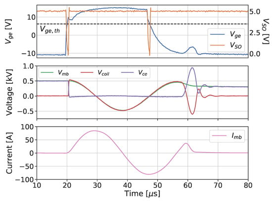
Figure 29.
Continued flow of current after end of second half cycle in the UW HiPeR-PIT discharge circuit, resulting in voltage ringing and loss of charge from the energy storage capacitors.
Capacitors
Future development of the main capacitor bank is expected to focus on in-vacuum thermal management and the reduction of capacitor ESR and ESL. Thermal management will be essential for high power in-vacuum operation of IPPTs, particularly in a continuous mode. Although water cooling schemes may be sufficient for initial laboratory testing, radiatively cooled banks will eventually be required. Since minimizing the mass and volume of the cooling infrastructure is desirable, characterizing the behavior of the main bank during extended operation at elevated temperatures should also be a focus. Reductions in ESR will improve the overall efficiency of the discharge circuit while decreases in ESL will minimize the stray inductance and, accordingly, increase the maximum of the discharge pulse. Such improvements may stem from adopting a distributed bank composed of many capacitors in parallel, from improved capacitor design, or even from refining the manner in which the bank is connected to the other components in the discharge circuit.
As mentioned in Section 4.1.2, only film and ceramic type capacitors have been used to date in IPPTs. Potential thermal issues were identified arising from the use of potted, or otherwise insulated, film capacitors operating in a thruster in continuous mode at high power [47]. For future efforts, an energy storage bank comprised of many smaller, high Q ceramic capacitors may be a potential solution. Doing so may make it easier to manage the bank temperature as well as reduce the overall ESR and ESL. While such a capacitor bank was eventually developed for the EMPT and, later, for the 30 kW ELF thruster [88], a rigorous direct comparison between the film and ceramic bank versions of these thrusters does not appear in the literature. Moreover, a detailed description of the design methodology used to guide the development of the ceramic capacitor banks was not provided. The development and testing of distributed ceramic capacitor energy storage banks, especially for higher power thrusters, is an area that could benefit from additional development. In particular, it must be confirmed that such a configuration could be operated over a range of temperatures without significant changes in bank capacitance or performance. A well documented method for effectively heat sinking such a capacitor bank would also be of value.
Mica capacitors are occasionally used as a more economical alternative to ceramic capacitors. A detailed trade study conducted in an effort to augment the Earth Observing-1 (EO-1) pulsed plasma thruster (PPT) with improved components found mica paper/foil capacitors to be the optimal choice for the discharge [108]. While ceramic multi-layer capacitors were also considered, at the time of the study they were found to be susceptible to structural failure after a relatively short number of pulses. In contrast, mica capacitors demonstrated exceptional robustness, lasting as many as 140 million pulses in some cases. Other identified advantages of mica capacitors included high radiation resistance, low ESR, good thermal stability, and inherent high voltage capability without the need for an insulating oil fill. The primary identified drawback was their relatively low energy density. Nonetheless, high power (∼100 kW) mica capacitors are commercially offered for high frequency (up to 100 MHz) applications which claim energy densities ≥400 kW/kg [109]. As such, a mica energy storage capacitor bank for IPPT applications may be worth investigation. In particular, a comparison between the mass, volume, and potential power throughput of a mica capacitor bank and a film and/or ceramic capacitor bank would be of interest.
One possible route for alleviating the thermal concerns associated with film-type capacitors is to use capacitors with built-in enhanced cooling. At present, several manufacturers offer film capacitors with convective, conductive, or water cooling options. Conduction-cooled oil-filled polypropylene capacitors available from manufacturer Celem™, for example, claim to handle up to 500 kW of power at frequencies up to several tens of kHz. Peak voltage and current ratings are on the order of a and a , respectively. While such specifications are quite promising, it should be noted that oil-filled capacitors are often avoided in space applications due to potential outgassing and contamination concerns. If, however, these (or similar) capacitors demonstrate the capability of stable in-vacuum operation, or if non-oil-filled versions demonstrating similar performance exist, they could be an attractive option for high power IPPTs.
Switches
The case for using solid-state switches in the IPPT discharge circuit has been discussed in multiple publications [9,16,92] and was summarized in Section 4.1.2. While both pulsed power thyristors [18] and IGBTs [43,86] have been implemented as discharge switches, no solid-state switch has been tested extensively enough to be considered a mature technology in the context of IPPT operation. Below, we make a number of suggestions for the advancement of solid-state switches in IPPT discharge circuits.
Intensive lifetime testing of solid-state switches is recommended to confidently determine whether they can reliably survive the large number of discharges (≳1010 pulses) expected over the course of a typical mission. Encouragingly, failure in time (FIT) rates for modern IGBTs in terrestiral applications are typically on the order of failures per device-hour [110,111]. While promising work by Kirtley et al. [85,86] demonstrated IGBT operation in excess of 109 pulses in benchtop PPU endurance testing efforts, it must be confirmed that this longevity can be replicated in an actual thruster. In addition, care should be exercised when attempting to broadly extend these findings, since switches in different IPPTs may be subjected to vastly different operating conditions. Extended lifetime testing of a wide range of solid-state switches, either as part of broader IPPT lifetime testing or under conditions meant to closely replicate IPPT operation, should be conducted before these devices can be considered to possess sufficient lifetime. Detailed reliability models for solid-state switches operating in a relevant space environment will likely need to be developed with a focus on identifying critical switch failure modes. The inclusion of realistic thermal and power cycling will be important when developing these models, since switch reliability and lifetime are critically impacted by these factors [110]. Moreover, implementation of condition monitoring systems is recommended so the performance and state of the devices over the course of lifetime testing can be carefully recorded, allowing for more accurate quantification of the risk of device failure.
It is of interest to determine the extent to which arrays of parallel and/or series connected switches can increase the range of discharge circuit parameters (i.e., charging voltage, peak current, and ) that can be accommodated by solid-state switches. Series connections are known to increase the effective voltage rating of the array while parallel connections improve the current handling capabilities. While switch arrays have seen some implementation in IPPT discharge circuits, primarily in the work of Poylio et al. [92] and Kirtley et al. [85], it is anticipated that there are practical limits on the the number of switches that can be incorporated into an array. The added complexity of simultaneously switching multiple devices may prevent the adoption of arrays with an excessive number of components.
Along similar lines, another relevant question is the extent to which switch arrays can be used to improve performance relative to a single monolithic switch. In terrestrial applications, such as high-power traction drives and high voltage DC transmission systems, large arrays of semiconductor devices are often connected in series and parallel to handle voltages and currents that could not be handled by a single device. In principle, the faster switching response and paralleled connections of an array can be used to reduce switching and conduction losses and improve net efficiency. Importantly, if the connections between switches in the array have a low inductance, this arrangement can also reduce the stray inductance of the circuit. Switch arrays are likely to have a thermal advantage over single devices. Their distributed nature makes heat sinking easier and switch overheating should become less of a concern. The improved efficiency also results in lower heat generation, further alleviating thermal concerns. Unique combinations of different types of switches may also provide advantages. The series connection of MOSFETs and multiple JFETs to form super cascodes, for example, has resulted in switch arrays capable of holding off large voltages while also exhibiting extremely fast switching times and low power losses [112]. It should be noted, however, that the improved performance of the switch array comes at the cost of greatly increased complexity. The trade-off between performance and complexity of a switching array must therefore be carefully analyzed. Given the additional complexity, it is anticipated that a rigorous evaluation of the reliability of multiple switch arrays will be necessary to determine whether they can be confidently used in IPPTs. This said, one added potential advantage of this complexity is that arrays, with their multiple parallel conduction paths, are much more immune to single-point failure that a single, monolithic switch. In addition, it may be possible to implement so-called “smart” arrays that can intelligently replace a failed switch in the array with a redundant backup.
Testing of switches implementing new wide bandgap (WBG) materials is a potential path for improvement. Switches using WBG materials such as silicon carbide (SiC) or gallium nitride (GaN) exhibit a number of advantages over older silicon (Si) devices. Most notably, they show great promise in applications where high voltages, high switching speeds, and high temperatures may be present [113]. This combination of characteristics makes them well suited for use in IPPT discharge circuits. At the time of writing, however, most commercially available WBG switches are not rated to the voltages and currents required for an IPPT system. While multiple switches could be connected in series and/or parallel to achieve the necessary ratings, this greatly increases the complexity of the switching. WBG switches with increased voltage and current ratings are presently a topic of active development, and devices with multi- ratings are likely to be commercially available in the near future. Given their many attractive advantages over Si devices, the incorporation of WBG switches, either as part of a larger array or as single devices once suitable ones become available, into IPPT discharge circuits presents itself as a potential path for advancement.
A detailed trade study of the various solid-state switch types is suggested to evaluate options and select optimal types for IPPT applications. While only pulsed power thyristors and IGBTs have been used in IPPT discharge circuits so far, other types of solid-state switches exist. Most notable are the power MOSFET and JFET. Each of these has their own advantages and disadvantages which should be carefully evaulated when selecting a solid-state discharge switch. Some of the most pertinent switching parameters are compared for an SCR, IGBT, and MOSFET in Table 3. It should be noted that the comparisons are meant to be general qualitative statements and that, given the wide range of devices in each category, there are likely many exceptions to the ordering listed. Given that no one switch is best in all areas, future work may seek to evaluate operating ranges that are best for each switch type.

Table 3.
Comparison of characteristics of selected solid-state switch types. Note that the designations in this table are for individual switches and not for arrays containing multiple switches.
Finally, certain WBG materials (namely silicon carbide) have demonstrated marked resilience to certain types of radiation induced failures [114,115]. At present, however, solid-state devices are still susceptible to heavy ion induced degradation and damage from single event effects (SEE) induced by neutrons, protons, or heavy ions [115]. Development of radiation resistant solid-state power switches, and power electronics in general, is a crucial step towards a flight-qualified IPPT.
IPPT PPUs
The primary role of the PPU in an IPPT is to recharge the capacitor to the nominal operating voltage between discharges. As such, the PPU essentially functions as a capacitor charging power supply (CCPS) which uses as its input the spacecraft bus power. A wide variety of CCPS designs have been reported in the literature for terrestrial applications, which range from pulsed laser and radar systems to railguns. To date, however, all known IPPT PPUs have used some variant of a boost converter or basic resonant charging circuit [43,47,85,86], due in part to the simplicity and effectiveness of these topologies. In an effort to improve on previous PPU designs, detailed circuit modeling of several widely used CCPS designs was conducted as part of a collaborative effort between the University of Washington (UW) and NASA-MSFC to develop a PPU for high repetition rate IPPTs. Particular attention was paid to so-called “resonant” CCPSs, which use resonant tanks to reduce switching losses. One of the most popular choices for a high power CCPS is an isolated full bridge topology with passive full bridge diode rectification. A circuit diagram of the general design is shown in Figure 30a, with four of the most popular resonant tank structures shown in Figure 30b–e. In this CCPS topology, as well as many other resonant CCPSs, a transformer is used to achieve voltage step-up while also providing isolation between the input and output of the supply. With the voltage gain across the transformer, the switches in the CCPS are only subject to the relatively low primary side voltage (the DC bus voltage in the case of an IPPT). This can greatly reduce switching stresses compared to non-isolated converters where the switches often must withstand the full output voltage. Nonetheless, simulations indicate that boost converter derived circuits employing multiple stages compared favorably to series, parallel, LLC, and LCC resonant converters when evaluated under conditions relevant to a high repetition rate IPPT PPU.
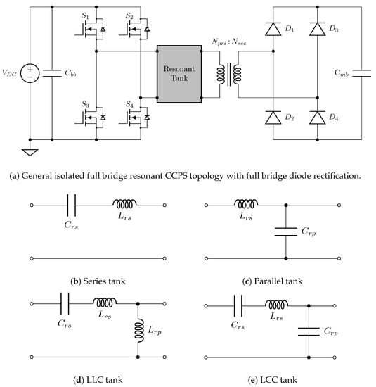
Figure 30.
(a) General isolated full bridge resonant CCPS topology and (b–e) popular resonant tank circuit options as denoted (note: many other resonant CCPS variations are possible).
The balance of this section proceeds with a discussion of a boost converter derived PPU for the UW HiPeR-PIT test article. However, before proceeding it should be noted that due to the large number of CCPSs simulated, the work by UW and NASA-MSFC did not attempt to optimize the topologies beyond what was specified by the basic design principles. For example, no attempt was made to implement sophisticated control algorithms for minimizing switching losses in the CCPSs. Thus, while these initial simulation results are a useful guide, the wide range of CCPS topologies that exist make any claims that it is the optimal design premature.
A simplified schematic of the UW HiPeR-PIT PPU designed for high repetition rate operation (1 kHz to 10 kHz) is presented in Figure 31. The design assumes a spacecraft bus voltage of 120 V to 200 V and uses four boost converter cells in parallel to charge the main capacitor bank to the nominal operating voltage of 2 kV to 3 kV. Paralleling boost cells allows a reduction in the current through each cell. Since the resistive losses in the circuit scale with the square of the current, this results in a 16-fold reduction in Ohmic heating for the same average current throughput. Detailed circuit modeling indicated that this design is capable of providing a factor of 15 voltage gain at powers ≳10 kW and efficiencies of ∼90%.
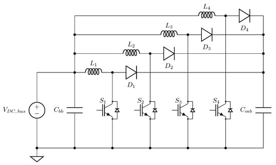
Figure 31.
Simplified circuit diagram of the UW HiPeR-PIT PPU designed to enable thruster operation at repetition rates from 1 kHz to 10 kHz.
Simulated waveforms of the main bank voltage and currents through the main bank, drive coil, and each of the boost switches, diodes, and inductors ( through ) are shown in Figure 32. Note that only one set of the boost switch, diode, and inductor currents is plotted, since the boost cells were modeled as identical and thus each cell will have the same simulated current. When operating at the nominal 1 kHz to 10 kHz repetition rate, the main bank must be recharged in roughly 10 μs to 100 μs. For a ∼1 μF bank, this corresponds to a PPU power throughput of 2 kW to 50 kW. For initial prototype testing, a 1 kW to 10 kW range was targeted. The paralleling of boost cells means that each cell only needs to handle a quarter of the total power, reducing stress on the components. In addition, this distributed architecture makes the dissipation of waste heat more manageable. Efforts are presently underway to test a brassboard-fidelity prototype of the UW HiPeR-PIT PPU to validate the accuracy of the simulated results.
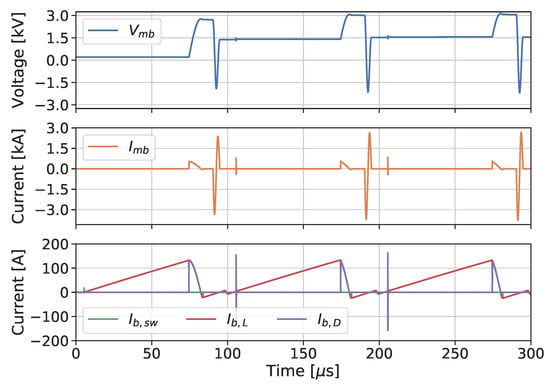
Figure 32.
Simulated waveforms of the main bank voltage () and currents through the main bank ( and each of the boost switches (), inductors (), and diodes () in the UW HiPeR-PIT PPU.
6.1.2. Circuit Modeling
In addition to improvements in modeling the plasma dynamics of an IPPT, higher fidelity models of both the discharge circuit and the PPU components are also envisioned as a path for advancement. In particular, more realistic models of the high power solid-state semiconductor switches are needed. Such models are expected to be important in obtaining accurate predictions of discharge and PPU circuit electrical efficiencies. This is especially true in the case of the PPU, where switching frequencies may be high enough that switching losses may become significant relative to conduction losses in the circuit. Moreover, accurately capturing the switching action may be important in predicting EMI characteristics for these circuits. The need for accurate models of other circuit components will depend on the topologies used in future PPU designs. While most IPPT PPU modeling to date has largely relied on relatively simple, or even idealized, representations of diodes, transformers, and various other passive and active elements, it is expected that more detailed, physically realistic models will need to be incorporated into future work. One of the most difficult challenges on this front is developing an accurate description of the charge carrier physics at the device level so as to permit circuit-level simulation. Moreover, there is also a need to couple the electrical properties of the circuit to the thermal state of both the circuit and the environment. Since many solid-state electronics have temperature dependent performance, the introduction of thermal effects is thought to be critical to achieving accurate simulation results. Recognizing the coupled nature of the electrical and thermal problems and being able to capture both in a single model is expected to be key to advancing IPPT power system simulations.
One possible route for improvement is the use of functional physics or product models supplied by the various power electronics and semiconductor manufacturers. For example, a functional physics model of an IGBT from Ref. [116] is presented as an example in Figure 33. Not all manufacturers supply models of this type that could be used in developing a model of components for use in a circuit simulation, so this may not be a viable option for all designs. In addition, the details of manufacturer models tend to be proprietary, with simulation files for the circuit components increasingly being encrypted so that they cannot be used to reverse engineer the products being modeled. The result is a “black box” that circuit designers must use without knowledge of the structure or inner workings of the device. This may or may not be acceptable, depending on what is being modeled and how critical it is to the overall design. An alternative would be to use higher fidelity circuit element models described in the literature [117,118,119,120]. While it is possible to replicate these models from scratch, implementations may also be readily found in numerous commercial circuit simulation packages. Notably, many of these models have been written in the Verilog-A/MS hardware description language and are available in the SaberRD™ power electronics and multi-domain physical system modeling software from Synopsys®.
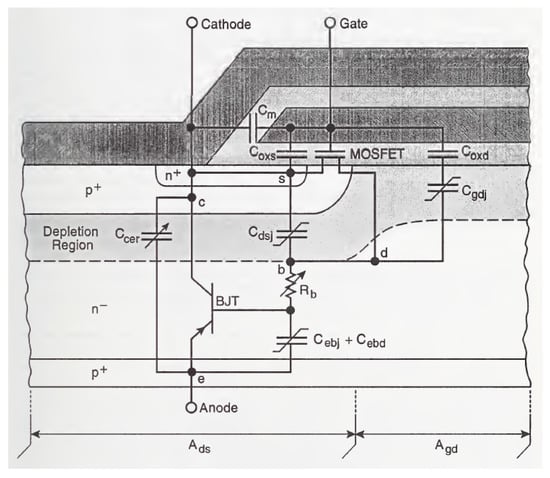
Figure 33.
Example of a functional physics model for an IGBT with circuit elements superimposed (from [116]).
6.2. Propellant Injection
It is generally understood that the distribution of injected propellant relative to the inductive coil affects IPPT operation [12,16,70]. For planar IPPTs, a uniform propellant distribution close to the coil face is thought to best facilitate current sheet formation [16]. However, achieving such a distribution can be a challenge in practice.
To date, all planar IPPTs have injected propellant from a central pylon structure. While this method has proven effective, it is possible that better injection schemes exist. If the coil geometry allows, one potential alternative is to flow propellant directly through gaps in the coil itself. If the gap area is sufficient to accommodate the desired mass flow rate and the gaps are evenly distributed, such an injection scheme promises a highly uniform propellant distribution.
The potential performance impacts of steady or quasi-steady gas injection in high repetition rate IPPTs require further study. While it is tentatively anticipated that most of the gas within the electromagnetic interaction distance will be accelerated, confirmation of this hypothesis is required. It may be the case that a minimum repetition rate exists below which injected gas travels too far from the coil face to be captured by the current sheet. Gas that is not captured will simply escape into space, leading to poor propellant use efficiency. It is also possible that steady gas injection, although slow relative to the discharge timescales, may result in higher gas densities near the coil face during the second half-cycle of the discharge, thereby increasing the likelihood of secondary current sheet formation. Che et al. [70] indicated that a secondary current sheet could contribute as much as 20% of the total impulse in an IPPT with pulsed gas injection, even though the gas density in the second sheet was much lower than the first. If more mass is available, it is possible that the performance impacts of the secondary sheet will grow in significance. However, the secondary sheet will never use the propellant in as efficient a manner as the initial current sheet because the second half-cycle current and levels are lower, resulting in significantly reduced acceleration. Finally, the axial gas profile encountered by the current sheet as it is accelerated may be different than in the pulsed gas injection case, which will likely alter the current sheet gas entrainment dynamics and corresponding thruster performance. Fast ion gauge measurements of the neutral density at various locations in front of the coil face or interferometric ion and neutral gas density measurements may be useful in determining the precise shape of the axial gas profile resulting from steady gas injection.
Propellant injection in FRC devices has not been as critical an issue because the configuration of the coils and the nature FRC operation and coupling with the plasma is significantly different than the open magnetic flux variants. One issue that does not appear to have been discussed in the literature is the relative importance of uniform propellant injection in FRCs, and how performance may be affected by nonuniform distributions.
6.3. Preionization
As discussed in Section 4.4, the preionization systems implemented to date in open magnetic flux IPPTs have met with limited success, at least in regards to increasing overall thruster performance. As a result, the general consensus is that preionization is of little benefit to performance in cases where the primary discharge is already capable of rapidly breaking down the propellant. Where preionization has proven useful is in reducing the per-pulse discharge energy and current rise rates required for current sheet formation. As such, future advancement efforts for preionization may focus on smaller, lower discharge energy open magnetic flux IPPTs.
Conversely, most closed magnetic flux FRC systems operate at lower discharge energy-per-pulse and must employ some means of preionization. Field-reversed theta-pinch FRCs start with either a partially ionized plasma or depend on the first half-cycle of the discharge to preionize the gas, while RMF-FRCs to date have all successfully employ some means of preionization.
Effective preionization is a key to high repetition rate IPPT operation. IPPTs operating at high repetition rates (i.e., ≳1 kHz) typically have per-pulse energies one to two orders of magnitude lower than IPPTs of similar power which operate at lower repetition rates (10 Hz to 100 Hz). At the ∼10 kW level, discharge energies in a high repetition rate IPPT may be no more than a few joules, as in most RMF-FRCs to date. In such cases, preionization is a necessity for timely gas breakdown and effective organization of the plasma and magnetic field structures.
Not all preionization systems are equally capable however. Work by Polzin [16] indicated the importance of distributing the preionization plasma uniformly over the coil face. This result was supported by initial data from testing of the UW HiPeR-PIT, which has suggested that centrally located RF preionization alone is less effective than using a two stage approach where a small capacitor bank is also discharged through the drive coil prior to the main discharge to further preionize the propellant. It should be recalled that prior efforts on a 30 cm diameter planar IPPT [12] indicated that using a smaller capacitor discharged through the drive coil for preionization could result in the plasma being pushed away from the coil face prior to the initiation of the main discharge. The UW HiPeR-PIT preionization system attempts to avoid this issue by triggering the main discharge after only a few cycles of the pulsed preionization discharge. The efficacy of this technique is still an open question.
Simulations have shown the importance of the axial distribution of the initial plasma on thruster performance [70]. Work by Dailey and Davis [12] indicated that a mirrored drive coil preionization system which compressed the initial plasma against the actual drive coil yielded measurable performance improvement. While this specific implementation was deemed impractical due to inevitable sputtering of the mirrored coil, a preionization system that could produce similar axial compression would be highly promising. However, in addition to plasma impingement on a coil that would compress the propellant on the drive coil face, there is also the possibility for significant electromagnetic coupling between the preionization and the drive coils.
Preionization in FRC devices is typically more uniform, though that may not be the case for the UM RMF-FRC with the use of a hollow cathode for the generation of a preionized plasma. It is unknown at this time if the spatial distribution of preionized propellant has any effect, positive or negative, on RMF-FRC performance.
7. Conclusions
We have presented a review of state-of-the-art IPPT research and development for both open and closed magnetic flux thruster types. The former is characterized by accelerators that rely on current sheets to entrain and accelerate propellant while the latter typically involves the formation of a compact toroid (FRC or plasmoid) with embedded magnetic fields. Numerous research groups have investigated thrusters of each type, with varying amounts of data available for each. In terms of measured, demonstrated performance, the PIT MK Va represents the present state-of-the-art for IPPTs. Lower discharge-energy-per-pulse FRC devices represent the state-of-the-art for continuous, repetition-rate operation. Modeling of both thruster variants have seen some success in predicting the scaling behavior in these thrusters, but there are still gross modeling assumptions involved at every level of fidelity that make it difficult to extract additional physical insights from the models. Modeling the different processes present in an IPPT (e.g., ionization, acceleration, gas entrainment, and other collisional processes) in a single formulation has never been accomplished and is quite difficult due in part to the relative times scales and complexities of each part of the problem. While various subsystems comprising IPPTs have been improved over the years, data on how these improvements affect the overall system performance are sparse. While the effects can be hypothesized based on models and physical expectations, these thrusters involve closely coupled processes and improvements must be quantified through testing at both the subsystem and overall thruster levels. The IPPT represents a promising and scalable technology for electric propulsion that could be extremely useful in the mission planning trade space due to a demonstrated ability to process a wide range of propellants, achieve high efficiency over a range of specific impulse values, and operate over a wide input power range. However, significant additional development and testing must be completed to quantify the performance of many proposed accelerator concepts and to generally increase the readiness level of these types of thrusters to the point where they can be seriously considered as propulsion systems for various missions.
Author Contributions
Co-author K.P. was responsible for the conceptualization of this article. All co-authors participated substantively in the investigation phase consisting of the literature research required to assemble the material, the visualization of the data and figures presented, the process of writing—original draft, and the writing—review & editing process to yield the final draft. All authors have read and agreed to the published version of the manuscript.
Funding
The work of J. Little and C. Promislow was funded by a NASA Marshall Space Flight Center Dual-Use Cooperative Agreement Notice award (agreement 80MSFC19M0026). The work of B. Jorns and J. Woods was funded by an Air Force Office of Scientific Research Young Investigator Program award (contract FA9550-19-1-0022).
Acknowledgments
The authors would like to thank Michael LaPointe and Jerry Hudgins for reviewing the manuscript and providing several comments that greatly helped improve the quality of this work.
Conflicts of Interest
The authors declare no conflict of interest. The funders had no role in the design of the study; in the collection, analyses, or interpretation of data; in the writing of the manuscript, or in the decision to publish the results.
References
- Jahn, R.G. Physics of Electric Propulsion; McGraw-Hill: New York, NY, USA, 1968. [Google Scholar]
- Lovberg, R.H.; Hayworth, B.R.; Gooding, T. The Use of a Coaxial Plasma Gun for Plasma Propulsion; Technical Report TR AE62-0678; Convair/General Dynamics: San Diego, CA, USA, 1962.
- Dailey, C.L.; Lovberg, R.H. The PIT MkV Pulsed Inductive Thruster; Technical Report NASA CR 191155; TRW Space & Technology Group: Redondo Beach, CA, USA, 1993. [Google Scholar]
- Hallock, A.K.; Martin, A.K.; Polzin, K.A.; Kimberlin, A.C.; Eskridge, R.H. Single- and Repetitive-Pulse Conical Theta-Pinch Inductive Pulsed Plasma Thruster Performance. IEEE Trans. Plasma Sci. 2015, 43, 433–443. [Google Scholar] [CrossRef]
- Kirtley, D.; Gallimore, A.D.; Haas, J.; Reilly, M. High density magnetized toroid formation and translation within XOCOT: An annular field reversed configuration plasma concept. In Proceedings of the 30th International Electric Propulsion Conference, Florence, Italy, 17–20 September 2007. IEPC Paper 2007-041. [Google Scholar]
- Martin, A.; Eskridge, R.; Lee, M.; Koelfgen, S.; Fimognari, P. The plasmoid thruster experiment (PTX). In Proceedings of the 46th APS Division of Plasma Physics Meeting, Savannah, GA, USA, 15–19 November 2004. Paper RM2.007. [Google Scholar]
- Polzin, K.A. Comprehensive review of planar pulsed inductive plasma thruster research and technology. J. Propuls. Power 2011, 27, 513–531. [Google Scholar] [CrossRef]
- Tuszewski, M. Field Reversed Configurations. Nucl. Fusion 1988, 28, 2033–2092. [Google Scholar] [CrossRef]
- Hrbud, I.; LaPointe, M.; Vondra, R.; Dailey, C.L.; Lovberg, R. Status of pulsed inductive thruster research. AIP Conf. Proc. 2002, 608, 627–632. [Google Scholar] [CrossRef]
- Lovberg, R.H.; Dailey, C.L. A PIT Primer; Technical Report TR 005; RLD Associates: Lebanon, PA, USA, 1994. [Google Scholar]
- Dailey, C.L. Pulsed Electromagnetic Thruster; Technical Report AFRPL-TR-71-107; TRW Systems Group: Redondo Beach, CA, USA, 1971. [Google Scholar]
- Dailey, C.L.; Davis, H.A. Pulsed Plasma Propulsion Technology; Technical Report AFRPL-TR-73-81; TRW Systems Group: Redondo Beach, CA, USA, 1973. [Google Scholar]
- Lovberg, R.H.; Dailey, C.L. Large Inductive Thruster Performance Measurement. AIAA J. 1982, 20, 971–977. [Google Scholar] [CrossRef]
- Dailey, C.L.; Lovberg, R.H. Pulsed Inductive Thruster Component Technology; Technical Report AFAL-TR-87-012; TRW Space and Technology Group: Redondo Beach, CA, USA, 1987. [Google Scholar]
- Choueiri, E.Y.; Polzin, K.A. Faraday acceleration with radio-frequency assisted discharge. J. Propuls. Power 2006, 22, 611–619. [Google Scholar] [CrossRef]
- Polzin, K.A. Faraday Accelerator With Radio-Frequency Assisted Discharge (FARAD). Ph.D. Thesis, Princeton University, Princeton, NJ, USA, 2006. Thesis Number 3147-T. [Google Scholar]
- Polzin, K.A.; Rose, M.F.; Miller, R. Laboratory-Model Integrated System FARAD Thruster. In Proceedings of the 44th AIAA/SAE/ASME/ASEE Joint Propulsion Conference, Hartford, CT, USA, 21–23 July 2008. AIAA Paper 2008-4821. [Google Scholar] [CrossRef]
- Martin, A.K.; Dominguez, A.; Eskridge, R.H.; Polzin, K.A.; Riley, D.P.; Perdue, K.A. Design and Testing of a Small Inductive Pulsed Plasma Thruster. In Proceedings of the 34th International Electric Propulsion Conference, Kobe-Hyogo, Japan, 4–10 July 2015. IEPC Paper 2015-50. [Google Scholar]
- Polzin, K.A.; Martin, A.K.; Eskridge, R.H.; Kimberlin, A.C.; Addona, B.M.; Devineni, A.P.; Dugal-Whitehead, N.R.; Hallock, A.K. Summary of the 2012 Inductive Pulsed Plasma Thruster Development and Testing Program; Technical Report NASA/TP-2013-217488; NASA-Marshall Space Flight Center: Huntsville, AL, USA, 2013.
- Steinhauer, L.C. Review of field-reversed configurations. Phys. Plasmas 2011, 18, 070501. [Google Scholar] [CrossRef]
- Barnes, D.C.; Seyler, C.E.; Anderson, D.V. Compact torus theory: MHD equilibrium and stability. In Proceedings of the US-Japan Joint Symposium on Compact Toruses and Energetic Particle Injection, Princeton, NJ, USA, 11–14 December 1979. [Google Scholar]
- Tuszewski, M.; Gupta, D.; Gupta, S.; Onofri, M.; Osin, D.; Deng, B.H.; Dettrick, S.A.; Hubbard, K.; Gota, H.; TAE Team. Equilibrium properties of hybrid field reversed configurations. Phys. Plasmas 2017, 24, 012502. [Google Scholar] [CrossRef]
- Guo, H.; Binderbauer, M.; Tajima, T.; Milroy, R.D.; Steinhauer, L.C.; Yang, X.; Garate, E.G.; Gota, H.; Korepanov, S.; Necas, A.; et al. Achieving a long-lived high-beta plasma state by energetic beam injection. Nat. Commun. 2015, 6, 6897. [Google Scholar] [CrossRef]
- Slough, J.; Votroubek, G.; Pihl, C. Creation of a high-temperature plasma through merging and compression of supersonic field reversed configuration plasmoids. Nucl. Fusion 2011, 51, 053008. [Google Scholar] [CrossRef]
- Gota, H.; Binderbauer, M.; Tajima, T.; Putvinski, S.; Tuszewski, M.; Deng, B.; Dettrick, S.; Gupta, D.; Korepanov, S.; Magee, R.; et al. Formation of hot, stable, long-lived field-reversed configuration plasmas on the C-2W device. Nucl. Fusion 2019, 59, 112009. [Google Scholar] [CrossRef]
- Rosenbluth, M.N.; Bussac, M.N. MHD stability of Spheromak. Nucl. Fusion 1979, 19, 489–498. [Google Scholar] [CrossRef]
- Armstrong, W.T.; Linford, R.K.; Lipson, J.; Platts, D.A.; Sherwood, E.G. Field-reversed experiments (FRX) on compact toroids. Phys. Fluids 1981, 24, 2068–2089. [Google Scholar] [CrossRef]
- Rej, D.J.; Armstrong, W.T.; Chrien, R.E.; Klingner, P.L.; Linford, R.K.; McKenna, K.F.; Sherwood, E.G.; Siemon, R.E.; Tuszewski, M.; Milroy, R.D. Experimental studies of field-reversed configuration translation. Phys. Fluids 1986, 29, 852–862. [Google Scholar] [CrossRef]
- Weber, T.; Intrator, T.; Smith, R. Plasma-gun-assisted field-reversed configuration formation in a conical θ-pinch. Phys. Plasmas 2015, 22, 042518. [Google Scholar] [CrossRef]
- Koelfgen, S.; Eskridge, R.; Lee, M.; Martin, A.; Hawk, C.; Fimognari, P. Magnetic and Langmuir probe measurements on the plasmoid thruster experiment (PTX). In Proceedings of the 40th AIAA/ASME/SAE/ASEE Joint Propulsion Conference and Exhibit, Fort Lauderdale, FL, USA, 11–14 July 2004. AIAA Paper 2004-4094. [Google Scholar] [CrossRef]
- Fimognari, P.J.; Cassibry, J.T.; Ims, K.E. Effects of Pre-ionization and Bias Field on Plasmoid Formation and Acceleration. In Proceedings of the 43rd AIAA/ASME/SAE/ASEE Joint Propulsion Conference and Exhibit, Cincinnati, OH, USA, 8–11 July 2007. AIAA Paper 2007-5262. [Google Scholar] [CrossRef]
- Weber, B.V.; Hinshelwood, D.D. He–Ne interferometer for density measurements in plasma opening switch experiments. Rev. Sci. Instrum. 1992, 63, 5199–5201. [Google Scholar] [CrossRef]
- Markusic, T.E. Current Sheet Canting in Pulsed Electromagnetic Accelerators. Ph.D. Thesis, Princeton University, Princeton, NJ, USA, 2002. Thesis Number 3102-T. [Google Scholar]
- Berkery, J.W. Current Sheet Mass Leakage in a Pulsed Plasma Accelerator. Ph.D. Thesis, Princeton University, Princeton, NJ, USA, 2005. Thesis Number 3144-T. [Google Scholar]
- Fimognari, P.J., III. A Magnetic and Interferometric Study of a Plasma Formed in a Conical-Theta-Pinch. Ph.D. Thesis, University of Alabama in Huntsville, Huntsville, AL, USA, 2007. [Google Scholar]
- Eskridge, R.H.; Fimognari, P.J.; Martin, A.K.; Lee, M.H. Design and Construction of the PT-1 Prototype Plasmoid Thruster. AIP Conf. Proc. 2006, 813, 474–483. [Google Scholar] [CrossRef]
- Slough, J.; Votroubek, G. Magnetically accelerated plasmoid (MAP) propulsion. In Proceedings of the 42nd AIAA/ASME/SAE/ASEE Joint Propulsion Conference & Exhibit, Sacramento, CA, USA, 9–12 July 2006. AIAA Paper 2004-4654. [Google Scholar] [CrossRef]
- Pahl, R.; Rovey, J. Pre-ionization plasma in an FRC test article. In Proceedings of the 50th AIAA Aerospace Sciences Meeting, Nashville, TN, USA, 9–12 July 2012. AIAA Paper 2012-194. [Google Scholar] [CrossRef]
- Pahl, R.A.; Rovey, J.L. Effects of DC Preionization Voltage and Radial Location on Pulsed Inductive Plasma Formation. IEEE Trans. Plasma Sci. 2015, 43, 3883–3888. [Google Scholar] [CrossRef]
- Hoffman, A.L.; Guo, H.Y.; Slough, J.T.; Tobin, S.J.; Schrank, L.S.; Reass, W.A.; Wurden, G.A. The TCS Rotating Magnetic Field FRC Current-Drive Experiment. Fusion Sci. Technol. 2002, 41, 92–106. [Google Scholar] [CrossRef]
- Blevin, H.A.; Thonemann, P.C. Plasma confinement using an alternating magnetic field. In Conference on Plasma Physics and Controlled Nuclear Fusion Research; Nuclear Fusion Supplement, Part 1; International Atomic Energy Agency: Vienna, Austria, 1962; pp. 55–60. [Google Scholar]
- Slough, J.; Kirtley, D.; Weber, T. Pulsed plasmoid propulsion: The ELF thruster. In Proceedings of the 31st International Electric Propulsion Conference, Ann Arbor, MI, USA, 20–24 September 2009. IEPC Paper 2009-265. [Google Scholar]
- Woods, J.M.; Sercel, C.L.; Gill, T.M.; Viges, E.; Jorns, B.A. Data-Driven Approach to Modeling and Development of a 30 kW Field-reversed Configuration Thruster. In Proceedings of the 36th International Electric Propulsion Conference, Vienna, Austria, 15–20 September 2019. IEPC Paper 2019-717. [Google Scholar]
- Weber, T.E.; Slough, J.T.; Kirtley, D. The electrodeless Lorentz force (ELF) thruster experimental facility. Rev. Sci. Instrum. 2012, 83, 113509. [Google Scholar] [CrossRef]
- Furukawa, T.; Takizawa, K.; Kuwahara, D.; Shinohara, S. Electrodeless plasma acceleration system using rotating magnetic field method. AIP Adv. 2017, 7, 115204. [Google Scholar] [CrossRef]
- Furukawa, T.; Shimura, K.; Hachisu, K.; Shinohara, S.; Yamamura, S.; Kuwahara, D. Electrodeless Helicon Plasma Thruster Employing Additional Electromagnetic Acceleration Methods. In Proceedings of the 36th International Electric Propulsion Conference, Vienna, Austria, 15–20 July 2019. IEPC Paper 2019-A-198. [Google Scholar]
- Kirtley, D.; Slough, J.; Pfaff, M.; Pihl, C. Steady operation of an electromagnetic plasmoid thruster. In Proceedings of the 5th Joint Army-Navy-NASA-Air Force (JANNAF) Spacecraft Propulsion Subcommittee Meeting, Huntsville, AL, USA, 2011. [Google Scholar]
- Justin, K.; Martin, R.; Sousa, E.M. High Fidelity Modeling of Field-Reversed Configuration (FRC) Thrusters; Technical Report AFRL-RQ-ED-TR-2017-0002; Air Force Research Laboratory: Edwards AFB, CA, USA, 2017. [Google Scholar]
- Li, G. Time-Resolved Emission Spectroscopy of Field Reversed Configuration Thruster; Technical Report AFRL-RQ-ED-VG-2016-276; Air Force Research Laboratory: Edwards AFB, CA, USA, 2016. [Google Scholar]
- Schmidt, G.; Jacobson, D.; Patterson, M.; Ganapathi, G.; Brophy, J.; Hofer, R. Electric Propulsion Research and Development at NASA. In Proceedings of the Space Propulsion Conference, Seville, Spain, 16–18 May 2018. Paper SP2018 00389. [Google Scholar]
- Weber, T. The Electrodeless Lorentz Force Thruster Experiment. Ph.D. Thesis, University of Washington, Seattle, WA, USA, 2010. [Google Scholar]
- Wong, A.R.; Toftul, A.; Polzin, K.A.; Pearson, J.B. Non-contact thrust stand calibration method for repetitively pulsed electric thrusters. Rev. Sci. Instrum. 2012, 83, 025103. [Google Scholar] [CrossRef] [PubMed]
- Brown, D.L.; Beal, B.E.; Haas, J.M. Air Force Research laboratory High Power Electric Propulsion Technology Development. In Proceedings of the IEEE Aerospace Conference, Big Sky, MT, USA, 6–13 March 2010. IEEEAC Paper 1549. [Google Scholar]
- Hill, C.S. Translation Studies on an Annular Field Reversed Configuration Device for Space Propulsion. Ph.D. Thesis, Michigan Technological University, Houghton, MI, USA, 2012. [Google Scholar]
- Phillips, J. Proposal to Produce Large Compact Toroids; Technical Report LA-8711-P; Los Alamos National Laboratory: Los Alamos, NM, USA, 1981.
- Alidieres, M.; Aymar, R.; Jourdan, P.; Koechlin, F.; Samain, A. Acceleration d’un plasma dans une configuration de striction. Plasma Phys. 1967, 9, 73–83. [Google Scholar] [CrossRef]
- Kirtley, D.E. Study of the Synchronous Operation of an Annular Field Reversed Configuration Device. Ph.D. Thesis, University of Michigan, Ann Arbor, MI, USA, 2008. [Google Scholar]
- Kirtley, D.; Pancotti, A.; Slough, J.; Pihl, C. Steady operation of an FRC thruster on Martian atmosphere and liquid water propellants. In Proceedings of the 48th AIAA/ASME/SAE/ASEE Joint Propulsion Conference & Exhibit, Atlanta, GA, USA, 30 July–1 August 2012. AIAA Paper 2012-4071. [Google Scholar] [CrossRef]
- Martin, A.K.; Eskridge, R.H. Electrical coupling efficiency of inductive plasma accelerators. J. Phys. D Appl. Phys. 2005, 38, 4168–4179. [Google Scholar] [CrossRef]
- Polzin, K.A.; Choueiri, E.Y. Performance optimization criteria for pulsed inductive plasma acceleration. IEEE Trans. Plasma Sci. 2006, 34, 945–953. [Google Scholar] [CrossRef]
- Polzin, K.A. Scaling and systems considerations in pulsed inductive plasma thrusters. IEEE Trans. Plasma Sci. 2008, 36, 2189–2198. [Google Scholar] [CrossRef]
- Polzin, K.A.; Reneau, J.P. Effect of Conductive Walls on the Performance of a Pulsed Inductive Thruster. IEEE Trans. Plasma Sci. 2009, 37, 359–364. [Google Scholar] [CrossRef]
- Polzin, K.A. Pulsed Inductive Plasma Acceleration: Optimization. In Encyclopedia of Plasma Technology; Shohet, J., Ed.; CRC Press: Boca Raton, FL, USA, 2016; pp. 1191–1200. [Google Scholar]
- Polzin, K.A.; Sankaran, K.; Ritchie, A.G.; Reneau, J.P. Inductive pulsed plasma thruster model with time-evolution of energy and state properties. J. Phys. D Appl. Phys. 2013, 46. [Google Scholar] [CrossRef]
- Mikellides, P.G.; Neilly, C. Modeling and Performance Analysis of the Pulsed Inductive Thruster. J. Propuls. Power 2007, 23, 51–58. [Google Scholar] [CrossRef]
- Mikellides, P.G.; Ratnayake, N. Modeling of the Pulsed Inductive Thruster Operating on Ammonia propellant. J. Propuls. Power 2007, 23, 854–862. [Google Scholar] [CrossRef]
- Mikellides, P.G.; Villarreal, J.K. High Energy Pulsed Inductive Thruster Modeling Operating with Ammonia Propellant. J. Appl. Phys. 2007, 102, 103301. [Google Scholar] [CrossRef]
- Allison, D.L.; Mikellides, P.G. A High-Temperature, Thermal Non-Equilibrium Equation of State for Ammonia. Int. J. Thermophys. 2006, 27, 794–819. [Google Scholar] [CrossRef]
- Mikellides, P.; Villarreal, J. Numerical Modeling of a Low Energy Pulsed Inductive Thruster. In Proceedings of the 44th AIAA/ASME/SAE/ASEE Joint Propulsion Conference & Exhibit, Hartford, CT, USA, 21–23 July 2008. AIAA Paper 2008-4726. [Google Scholar] [CrossRef]
- Che, B.X.; Cheng, M.S.; Li, X.K.; Guo, D.W. Physical mechanisms and factors influencing inductive pulsed plasma thruster performance: A numerical study using an extended magnetohydrodynamic model. J. Phys. D Appl. Phys. 2018, 51, 365202. [Google Scholar] [CrossRef]
- Hallock, A.K. Effect of Inductive Coil Geometry on the Operating Characteristics of a Pulsed Inductive Plasma Accelerator. Ph.D. Thesis, Princeton University, Princeton, NJ, USA, 2012. Thesis Number 3252-T. [Google Scholar]
- Martin, A.K. Performance scaling of inductive pulsed plasma thrusters with coil angle and pulse rate. J. Phys. D Appl. Phys. 2016, 49, 025201. [Google Scholar] [CrossRef]
- Polzin, K.; Rose, M.F.; Miller, R.; Best, S.; Owens, T.; Dankanich, J. Design of a low-energy FARAD thruster. In Proceedings of the 43rd AIAA/ASME/SAE/ASEE Joint Propulsion Conference & Exhibit, Cincinnati, OH, USA, 8–11 July 2007. AIAA Paper 2007-5257. [Google Scholar] [CrossRef]
- Woods, J.M.; Jorns, B.A.; Gallimore, A.D. Circuit Modeling of Rotating Magnetic Field Field-reversed Configuration Thrusters. In Proceedings of the AIAA Propulsion and Energy Forum, Cincinnati, OH, USA, 9–11 July 2018. AIAA paper 2018-4911. [Google Scholar] [CrossRef]
- Hugrass, W.N.; Okada, T.; Ohnishi, M. Plasma-circuit Interactions in Rotating Magnetic Field Current Drive. Plasma Phys. Control. Fusion 2008, 50, 055008. [Google Scholar] [CrossRef]
- Little, J.; Cornella, B.; Pancotti, A.; Kirtley, D. Scaling of FRC Thrusters with Neutral Entrainment. In Proceedings of the 8th Joint Army-Navy-NASA-Air Force (JANNAF) Spacecraft Propulsion Subcommittee Meeting, Phoenix, AZ, USA, 5–8 December 2016. [Google Scholar]
- Ji, H.; Yamada, M.; Kulsrud, R.; Pomphrey, N.; Himura, H. Studies of Global Stability of Field-Reversed Configuration Plasmas Using a Rigid Body Model. Phys. Plasmas 1998, 5, 3685–3693. [Google Scholar] [CrossRef]
- Niemela, C.S.; King, L.B. Numerical Optimization of an Annular Field Reversed Configuration Translation Experiment. In Proceedings of the 31st International Electric Propulsion Conference, Ann Arbor, MI, USA, 20–24 September 2009. IEPC paper 2009-008. [Google Scholar]
- Milroy, R.D.; Brackbill, J.U. Numerical studies of a field-reversed theta-pinch plasma. Phys. Fluids 1982, 25, 775–783. [Google Scholar] [CrossRef]
- Slough, J. Multi-megawatt propulsion based on a compact toroid thruster. In Proceedings of the 29th International Electric Propulsion Conference, Princeton, NJ, USA, 31 October–4 November 2005. IEPC paper 2005-296. [Google Scholar]
- Meier, E.T. Modeling Plasmas with Strong Anisotropy, Neutral Fluid Effects, and Open Boundaries. Ph.D. Thesis, University of Washington, Seattle, WA, USA, 2011. [Google Scholar]
- Milroy, R.D. A numerical study of rotating magnetic fields as a current drive for field reversed configurations. Phys. Plasmas 1999, 6, 2771–2780. [Google Scholar] [CrossRef]
- Brackbill, J.; Cambier, J.L.; Gimelshein, N.E.; Gimelshein, S.F. Numerical analysis of neutral entrainment effect on field-reversed configuration thruster efficiency. J. Propuls. Power 2014, 30, 1450–1458. [Google Scholar] [CrossRef]
- Patel, M.R. Spacecraft Power Systems; CRC Press: Boca Raton, FL, USA, 2004. [Google Scholar]
- Kirtley, D.; Pihl, J.; Pihl, C. Development of a steady operating pulsed power system for FRC and inductive thrusters. In Proceedings of the 33rd International Electric Propulsion Conference, Washington, DC, USA, 6–10 October 2013. IEPC Paper 2013-361. [Google Scholar]
- Kirtley, D.; Pihl, J.; Bernhard, B.; Goff, J. Development, Vibration, and Thermal Characterization of a Steady Operating Pulsed Power System for FRC Thrusters; Technical Report AFRL-RQ-ED-TP-2015-139; Air Force Research Laboratory: Edwards AFB, CA, USA, 2015. [Google Scholar]
- Polzin, K.A.; Rose, M.F.; Miller, R. Operational Characteristics of a Low-Energy FARAD Thruster. In Proceedings of the 44th AIAA/SAE/ASME/ASEE Joint Propulsion Conference, Hartford, CT, USA, 21–23 July 2008. AIAA Paper 2008-5011. [Google Scholar] [CrossRef]
- Pancotti, A.P.; Little, J.M.; Neuhoff, J.S.; Cornella, B.M.; Kirtley, D.E.; Slough, J.T. Electrodeless Lorentz Force (ELF) Thruster for ISRU and Sample Return Mission. In Proceedings of the 34th International Electric Propulsion Conference, Kobe-Hyogo, Japan, 4–10 July 2015. IEPC Paper 2015-67. [Google Scholar]
- Owens, T.L. A pulse-compression-ring circuit for high-efficiency electric propulsion. Rev. Sci. Instrum. 2008, 79, 034701. [Google Scholar] [CrossRef] [PubMed]
- Bernardes, J.; Merryman, S. Parameter analysis of a single stage induction mass driver. In Proceedings of the 5th IEEE International Pulsed Power Conference, Washington, DC, USA, 10–12 June 1985; IEEE Paper PI-27. pp. 552–555. [Google Scholar]
- Toftul, A.; Polzin, K.A.; Martin, A.K.; Hudgins, J.L. Testing of Diode-Clamping in an Inductive Pulsed Plasma Thruster Circuit. In Proceedings of the 50th AIAA/ASME/SAE/ASEE Joint Propulsion Conference, Cleveland, OH, USA, 28–30 July 2014. AIAA Paper 2014–3503. [Google Scholar] [CrossRef]
- Poylio, J.H.; Russell, D.; Goldstein, W.; Jackson, B.; Lovberg, R.H.; Dailey, C.L. Pulsed inductive thruster: Flight-scale proof of concept demonstrator. In Proceedings of the 40th AIAA/ASME/SAE/ASEE Joint Propulsion Conference & Exhibit, Fort Lauderdale, FL, USA, 11–14 July 2004. AIAA Paper 2004-3640. [Google Scholar] [CrossRef]
- Raines, T. Propellant Mass Scaling and Decoupling and Improved Plasma Coupling in a Pulsed Inductive Thruster. Master’s Thesis, Arizona State University, Tempe, AZ, USA, 2018. [Google Scholar]
- Frisbee, R.H. Evaluation of High-Power Solar Electric Propulsion Using Advanced Ion, Hall, MPD, and PIT Thrusters for Lunar and Mars Cargo Missions. In Proceedings of the 42nd AIAA/SAE/ASME/ASEE Joint Propulsion Conference & Exhibit, Sacramento, CA, USA, 9–12 July 2006. AIAA Paper 2006-4465. [Google Scholar] [CrossRef]
- Burkhardt, W.M.; Crapuchettes, J.M.; Addona, B.M.; Polzin, K.A. Development of Long-Lifetime Pulsed Gas Valves for Pulsed Electric Thrusters. In Proceedings of the 51st AIAA/SAE/ASEE Joint Propulsion Conference & Exhibit, Orlando, FL, USA, 27–29 July 2015. AIAA Paper 2015-4187. [Google Scholar] [CrossRef]
- Burkhardt, W. Fast Acting Control Valve; Technical Report, NASA SBIR Phase 2 Contract NNX15CM11C; WASK Engineering, Inc.: Cameron Park, CA, USA, 2017. [Google Scholar]
- Dailey, C.L.; Lovberg, R.H. Current sheet structure in an inductive-impulsive plasma accelerator. AIAA J. 1972, 10, 125–129. [Google Scholar] [CrossRef]
- Hallock, A.; Choueiri, E.; Polzin, K. Current sheet formation in a conical theta pinch faraday accelerator with radio-frequency assisted discharge. In Proceedings of the 44th AIAA/ASME/SAE/ASEE Joint Propulsion Conference & Exhibit, Hartford, CT, USA, 21–23 July 2008; p. 5201. [Google Scholar] [CrossRef]
- Milroy, R.D.; Brackbill, J.U. Toroidal magnetic field generation during compact toroid formation in a field-reversed theta pinch and a conical theta pinch. Phys. Fluids 1986, 29, 1184–1195. [Google Scholar] [CrossRef]
- Milroy, R.D.; Kim, C.C.; Sovinec, C.R. Extended magnetohydrodynamic simulations of field reversed configuration formation and sustainment with rotating magnetic field current drive. Phys. Plasmas 2010, 17, 062502. [Google Scholar] [CrossRef]
- Choueiri, E. Scaling of thrust in self-field magnetoplasmadynamic thrusters. J. Propuls. Power 1998, 14, 744–753. [Google Scholar] [CrossRef]
- Takahashi, K.; Lafleur, T.; Charles, C.; Alexander, P.; Boswell, R.W. Electron diamagnetic effect on axial force in an expanding plasma: Experiments and theory. Phys. Rev. Lett. 2011, 107, 235001. [Google Scholar] [CrossRef] [PubMed]
- Sheppard, A.J.; Little, J. Scaling laws for electrodeless plasma propulsion with water vapor propellant. Plasma Sources Sci. Technol. 2020, 29, 045007. [Google Scholar] [CrossRef]
- Florescu-Mitchell, A.I.; Mitchell, J.B.A. Dissociative recombination. Phys. Rep. 2006, 430, 277–374. [Google Scholar] [CrossRef]
- Rapp, D.; Francis, W.E. Charge exchange between gaseous ions and atoms. J. Chem. Phys. 1962, 37, 2631–2645. [Google Scholar] [CrossRef]
- Singh, R.; Cooper, J.A.; Melloch, M.R.; Chow, T.P.; Palmour, J.W. SiC power Schottky and PiN diodes. IEEE Trans. Electron Devices 2002, 49, 665–672. [Google Scholar] [CrossRef]
- Morisette, D.T.; Cooper, J.A. Theoretical comparison of SiC PiN and Schottky diodes based on power dissipation considerations. IEEE Trans. Electron Devices 2002, 49, 1657–1664. [Google Scholar] [CrossRef]
- Benson, S.W.; Frus, J.R. Advanced pulsed plasma thruster electrical components. In Proceedings of the 37th AIAA/ASME/SAE/ASEE Joint Propulsion Conference and Exhibit, Salt Lake City, UT, USA, 8–11 July 2001. AIAA Paper 2001-3894. [Google Scholar] [CrossRef]
- Celem Power Capacitors. Conduction-Cooled Capacitor; CPRI 300; Celem Power Capacitors: Jerusalem, Israel, 2015. [Google Scholar]
- Yang, S.; Xiang, D.; Bryant, A.; Mawby, P.; Ran, L.; Tavner, P. Condition monitoring for device reliability in power electronic converters: A review. IEEE Trans. Power Electron. 2010, 25, 2734–2752. [Google Scholar] [CrossRef]
- Hudgins, J.L.; De Doncker, R.W. Power semiconductor devices: For variable speed drives. IEEE Ind. Appl. Mag. 2012, 18, 18–25. [Google Scholar] [CrossRef]
- Gao, B.; Morgan, A.J.; Xu, Y.; Zhao, X.; Hopkins, D.C. 6.0 kV, 100 A, 175 kHz super cascade power module for medium voltage, high power applications. In Proceedings of the IEEE Applied Power Electronics Conference and Exposition (APEC), San Antonio, TX, USA, 4–8 March 2018; pp. 1288–1293. [Google Scholar] [CrossRef]
- Millan, J.; Godignon, P.; Perpiñà, X.; Pérez-Tomás, A.; Rebollo, J. A survey of wide bandgap power semiconductor devices. IEEE Trans. Power Electron. 2013, 29, 2155–2163. [Google Scholar] [CrossRef]
- Casady, J.B.; Johnson, R.W. Status of silicon carbide (SiC) as a wide-bandgap semiconductor for high-temperature applications: A review. Solid-State Electron. 1996, 39, 1409–1422. [Google Scholar] [CrossRef]
- Boomer, K.; Lauenstein, J.M.; Hammoud, A. Body of Knowledge for Silicon Carbide Power Electronics; Technical Report; NASA Electronic Parts and Packaging (NEPP) Program, Office of Safety and Mission Assurance: Washington, DC, USA, 2016.
- Hefner, A.R., Jr. INSTANT—IGBT Network Simulation and Transient ANalysis Tool; Spec. Publ. 400-88; National Institute of Standards and Technology: Washington, DC, USA, 1992.
- Perez, S.; Kotecha, R.M.; Rashid, A.U.; Hossain, M.M.; Vrotsos, T.; Francis, A.M.; Mantooth, A.H.; Santi, E.; Hudgins, J.L. A datasheet driven unified Si/SiC compact IGBT model for N-channel and P-channel devices. IEEE Trans. Power Electron. 2018, 34, 8329–8341. [Google Scholar] [CrossRef]
- Hefner, A.R.; Diebolt, D.M. An experimentally verified IGBT model implemented in the Saber circuit simulator. IEEE Trans. Power Electron. 1994, 9, 532–542. [Google Scholar] [CrossRef]
- Mudholkar, M.; Ahmed, S.; Ericson, M.N.; Frank, S.S.; Britton, C.L.; Mantooth, H.A. Datasheet driven silicon carbide power MOSFET model. IEEE Trans. Power Electron. 2013, 29, 2220–2228. [Google Scholar] [CrossRef]
- Tan, C.M.; Tseng, K.J. Using power diode models for circuit simulations—A comprehensive review. IEEE Trans. Ind. Electron. 1999, 46, 637–645. [Google Scholar] [CrossRef]
© 2020 by the authors. Licensee MDPI, Basel, Switzerland. This article is an open access article distributed under the terms and conditions of the Creative Commons Attribution (CC BY) license (http://creativecommons.org/licenses/by/4.0/).

