Deployment of Solar Sails by Joule Effect: Thermal Analysis and Experimental Results

 ,
,  ,
,  ,
, 
Abstract
1. Introduction
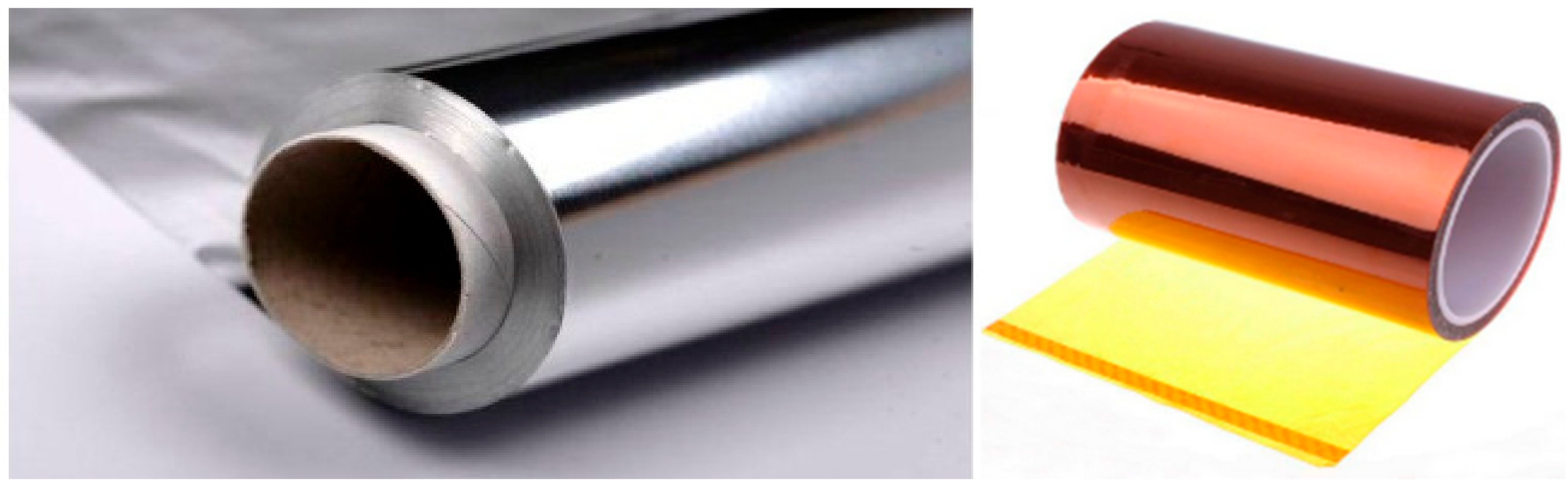
2. Materials
3. Thermal Analysis: Mathematical Models
4. Experimental Results
5. Discussion
6. Conclusions
Author Contributions
Funding
Acknowledgments
Conflicts of Interest
Nomenclature
| m | mass (kg) |
| c | specific heat (320 J kg−1 K−1) |
| R | electric resistance (Ω) |
| ρt | Ni-Ti Resistivity (0.80 Ω mm2/m) |
| I | electric current (A) |
| V | voltage (V) |
| v | volume |
| Tamb | ambient temperature (K) |
| σ | Boltzmann constant (5.67 × 10⁻⁸ W m−2 K−4) |
| h | convective heat transfer coefficient |
| ε | emissivity (0.17) |
| A | area (m2) |
| Af | austenite finish temperature (°C) |
| α | thermal diffusivity (derived, m2 s−1) |
| ρ | density (NiTi 6.45, Al 2.7, Kapton 1.42, kg/dm3) |
| Ioβ | real solar irradiance (615 W/m2) |
| SMA | shape memory alloy |
References
- Tsiolkowsky, K.E. Extension of Man into Outer Space. Proc. Symp. Jet Propuls. 1921, 2. [Google Scholar]
- Tsuda, Y.; Mori, O.; Funase, R.; Sawada, H.; Yamamoto, T.; Saiki, T.; Endo, T.; Kawaguchi, J. Flight status of IKAROS deep space solar demonstrator. Acta Astronaut. 2011, 69, 833–840. [Google Scholar] [CrossRef]
- Niccolai, L.; Anderlini, A.; Mengali, G.; Quarta, A.A. Impact of solar sail wind fluctuations on electric sail mission design. Aerosp. Sci. Technol. 2018, 82, 38–45. [Google Scholar] [CrossRef]
- Block, J.; Straubel, M.; Wiedemann, M. Ultralight deployable booms for solar sails and other large gossamer structures in space. Acta Astronaut. 2011, 68, 984–992. [Google Scholar] [CrossRef]
- Johnson, L.; Young, R.; Montgomery, E.; Alhorn, D. Status of solar sail technology within NASA. Adv. Space Res. 2011, 48, 1687–1694. [Google Scholar] [CrossRef]
- Roman Kezera, Y.A. Thickness requirement for solar sail foils. Acta Astronaut. 2009, 65, 507–518. [Google Scholar]
- Dalla Vedova, F.; Henrion, H.; Leipold, M.; Girot, T.; Vaudemont, R.; Belmonte, T.; Fleury, K.; Le Couls, O. The Solar Sail Materials (SSM) Project—Status of activities. Adv. Space Res. 2011, 48, 1922–1926. [Google Scholar] [CrossRef]
- Fernandez, J.M.; Lappas, V.J.; Daton-Lovett, A.J. Completely stripped solar sail concept using bi-stable reeled composite booms. Acta Astronaut. 2011, 69, 78–85. [Google Scholar] [CrossRef]
- Fu, B.; Eke, F. Further investigation of the body torques on a square solar sail due to the displacement of the sail attachment points. Aerosp. Sci. Technol. 2016, 50, 281–294. [Google Scholar] [CrossRef]
- Mariner 10, NASA. National Space Science Data Center (NSSDC). Available online: https://nssdc.gsfc.nasa.gov/nmc/spacecraft/display.action?id=1973-085A (accessed on 20 November 2020).
- Leipold, M.; Garner, C.E.; Freeland, R.; Herrmann, A.; Noca, M.; Pagel, G.; Sebolt, W.; Sprague, G.; Unckenbold, W. Odissee—A proposal for demonstration of a solar sail in earth orbit. Acta Astronaut. 1999, 45, 557–566. [Google Scholar] [CrossRef]
- Mori, O.; Sawada, H.; Funase, R.; Endo, T.; Morimoto, M.; Yamamoto, T.; Tsuda, Y.; Kawakatsu, Y.; Kawaguchi, J. Development of first Solar Power Sail Demonstrator—Ikaros. In Proceedings of the 21st International Symposium on Space Flight Dynamics, Toulouse, France, 28 September–2 October 2009. [Google Scholar]
- Johnson, L.; Whorton, M.; Heaton, A.; Pinson, R.; Laue, G.; Adams, C. NanoSail-D: A solar sail demonstration mission. Acta Astronaut. 2011, 68, 571–575. [Google Scholar] [CrossRef]
- Nehrenz, M.; Diaz, A.; Svitek, T.; Biddy, C. Initial design and simulation of the LightSail-1 attitude determination and control system. In Proceedings of the 2nd International Symposium on Solar Sailing, New York, NY, USA, 20–22 July 2010; pp. 135–140. [Google Scholar]
- MacNeal, R.H. The Heliogyro-An Interplanetary Flying Machine; NTRS—NASA Technical Reports Server: Santa Barbara, CA, USA, 1967. [Google Scholar]
- Burton, R.L.; Coverstone, V.L.; Hargens-Rysanek, J.; Ertmer, K.; Botter, T.; Benavides, G.F.; Woo, B.; Carroll, D.L.; Gierow, P.; Farmer, G.; et al. Ultrasail—Ultralightweight solar sail concept. In Proceedings of the 41st AIAA/ASME/SAE/ASEE Joint Propulsion Conference, Tucson, AZ, USA, 10–13 July 2005. [Google Scholar]
- Costanza, G.; Tata, M.E. Design and characterization of a small-scale solar sail deployed by NiTi Shape Memory Actuators. Procedia Struct. Integr. 2016, 2, 1451–1456. [Google Scholar] [CrossRef][Green Version]
- Costanza, G.; Tata, M.E. A novel methodology for solar sail opening employing shape memory alloy elements. J. Intell. Mater. Syst. Struct. 2018, 29, 1793–1798. [Google Scholar] [CrossRef]
- Costanza, G.; Leoncini, G.; Quadrini, F.; Tata, M.E. Design and characterization of a small-scale solar sail prototype by integrating NiTi SMA and carbon fibre composite. Adv. Mater. Sci. Eng. 2017, 2017, 8467971. [Google Scholar] [CrossRef]
- Otsuka, K.; Ren, X. Physical metallurgy of Ti-Ni-based shape memory alloys. Progr. Mater. Sci. 2005, 50, 511–678. [Google Scholar] [CrossRef]
- Costanza, G.; Tata, M.E.; Libertini, R. Effect of temperature on the mechanical behavior of Ni-Ti Shape Memory Sheets. In Proceedings of the TMS2016 145th Annual Meeting Supplemental Proceedings, Nashville, TN, USA, 14–18 February 2016; pp. 433–439. [Google Scholar]
- Costanza, G.; Paoloni, S.; Tata, M.E. IR thermography and resistivity investigations on Ni-Ti shape memory alloys. Key Eng. Mater. 2014, 605, 23–26. [Google Scholar] [CrossRef]
- Costanza, G.; Tata, M.E.; Calisti, C. Nitinol one-way shape memory springs: Thermomechanical characterization and actuator design. Sens. Actuators A Phys. 2010, 157, 113–117. [Google Scholar] [CrossRef]
- Bovesecchi, G.; Corasaniti, S.; Costanza, G.; Tata, M.E. A Novel Self-Deployable Solar Sail System Activated by Shape Memory Alloys. Aerospace 2019, 6, 78. [Google Scholar] [CrossRef]
- Boschetto, A.; Bottini, L.; Costanza, G.; Tata, M.E. Shape-memory activated self-deployable solar sails: Small-scale prototypes manufacturing and planarity analysis by 3D laser scanner. Actuators 2019, 8, 38. [Google Scholar] [CrossRef]
- Costanza, G.; Tata, M.E. Shape memory alloys for aerospace, recent developments, and new applications: A short review. Materials 2020, 13, 1856. [Google Scholar] [CrossRef] [PubMed]


| Configuration | Number of Foldings | Surface Reduction | Electrical Junction Surface | Number of SMA Elements | Opening Times | Current Voltage |
|---|---|---|---|---|---|---|
| 1 | 3 | 75% | 10.1% | 11 | 95 s | 5 A 2.8 V |
| 2 | 3 | 75% | 8.2% | 11 | 40 s | 5 A 2.6 V |
| 3 | 4 | 93% | 8.1% | 12 | 75 s | 7.5 A 3.0 V |
| 4 | 4 | 93% | 5.5% | 15 | 55 s | 6.0 A 3.6 V |
| 5 | 4 | 75% | 5.5% | 13 | 100 s | 3.1 A 2.2 V |
| 6 | 3 | 75% | 5.5% | 13 | 70 s | 3.1 A 2.5 V |
Publisher’s Note: MDPI stays neutral with regard to jurisdictional claims in published maps and institutional affiliations. |
© 2020 by the authors. Licensee MDPI, Basel, Switzerland. This article is an open access article distributed under the terms and conditions of the Creative Commons Attribution (CC BY) license (http://creativecommons.org/licenses/by/4.0/).
Share and Cite
Bovesecchi, G.; Corasaniti, S.; Costanza, G.; Piferi, F.P.; Tata, M.E. Deployment of Solar Sails by Joule Effect: Thermal Analysis and Experimental Results. Aerospace 2020, 7, 180. https://doi.org/10.3390/aerospace7120180
Bovesecchi G, Corasaniti S, Costanza G, Piferi FP, Tata ME. Deployment of Solar Sails by Joule Effect: Thermal Analysis and Experimental Results. Aerospace. 2020; 7(12):180. https://doi.org/10.3390/aerospace7120180
Chicago/Turabian StyleBovesecchi, Gianluigi, Sandra Corasaniti, Girolamo Costanza, Fabrizio Paolo Piferi, and Maria Elisa Tata. 2020. "Deployment of Solar Sails by Joule Effect: Thermal Analysis and Experimental Results" Aerospace 7, no. 12: 180. https://doi.org/10.3390/aerospace7120180
APA StyleBovesecchi, G., Corasaniti, S., Costanza, G., Piferi, F. P., & Tata, M. E. (2020). Deployment of Solar Sails by Joule Effect: Thermal Analysis and Experimental Results. Aerospace, 7(12), 180. https://doi.org/10.3390/aerospace7120180