Abstract
Future aircraft design highly depends on the successful implementation of new technologies. However, the gap between conventional designs and new visions often comes with a high financial risk. This significantly complicates the integration of innovations. Scaled unmanned aircraft systems (UAS) are an innovative and cost-effective way to get new configurations and technologies in-flight. Therefore the Institute of Aircraft Design developed the e-Genius-Mod taking into account all relevant similitude requirements. It is a scale model of the electric motor glider e-Genius. Since the Reynolds number for the free-flight model cannot be adhered to, an airfoil was developed with lift-to-drag and lift-to-angle-of-attack courses reproducing the full-scale e-Genius flight characteristics. This will enable testing and assessment of new aviation technologies in a scaled version with an opportunity for free-flight demonstration in relevant environment.
1. Introduction
This article is an extension of the conference paper “UAS as flexible and innovative test platform for aircraft configuration and systems testing” [1].
For many years unmanned aircraft systems (UAS) have played an important role in aviation research. UAS were used especially for development and testing of new aircraft configurations in different research projects. For example, the configuration of a blended wing body for commercial aviation was successfully tested with a scaled unmanned free-flying platform. The collected flight data gave first insights into flight behavior [2,3] as well as the impact on passenger comfort of such an unknown configuration in flight. Beside Computational Fluid Dynamics (CFD) analysis and wind tunnel tests, UAS free flight models can be a cost-efficient alternative for the investigation of new aircraft configurations, as shown in various research projects.
1.1. Future Challenges
Beside classic approaches to aircraft design, new requirements and technologies have to be considered in future designs to meet imminent political and economic requirements. “Flightpath 2050—Europe’s Vision for Aviation” defines specific challenges for future aircraft [4]. One important design driver is to protect the environment, with requirements to:
- Reduce CO2 and NOx emissions
- Reduce noise emission
- Taxi emission free
To meet these requirements, new technologies are required in aviation, such as for example electric or hybrid-electric powertrains. Especially in the field of emission reduction, these technologies can offer an advantage over conventional propulsion systems. However, the efficient and profitable use of these propulsion systems also requires an adaptation of the aircraft configuration. This technology is already partially available in innovative research concepts, which must be brought to a demonstration in flight. Once tested and proven in flight the technology will have a bigger impact than on a laboratory test level. These technology changes pose a high risk when it comes to truly redeveloping and certifying such systems for commercial use. A look at the development costs for new aircraft reveals a significant increase [4] in development costs per seat. This cost increase is aggravated when new technologies are used, such as for the A350 or B787 [5]. This is one of the main reasons why todays aircraft configurations typically rely on well-known configuration types and technologies. Commercialization of novel technologies therefore typically takes a long time from the actual invention to market entry.
To be able to meet future challenges as quickly and efficiently as possible and to minimize the financial risk for the manufacturers, the challenge will be to offer an economically viable way to bring innovative technologies to an appropriate technology readiness level (TRL), where they get interesting for commercialization due to a significantly lower technological and financial risk. In addition to risk reduction, development time also has to be reduced. Today the development of new technologies (flying components) for aviation takes around 20 years from TRL1 to TRL9 [5].
1.2. Accelerate Technology Readiness
Testing aircraft models in wind tunnels is an established technique of validating new prototype designs. An alternative is the testing with free-flight models based on a UAS test platform. This form of investigating flight characteristics, using scaled models, is mainly used in research projects, with a focus on the investigation of the flight dynamics of novel unconventional aircraft configurations.
Over and above the investigation of new aircraft configurations, UAS can be used as testbeds for new aircraft technologies. The process to bring new technologies or research concepts for aviation to flight is time and cost intensive. This fact proves to be a major hurdle to a fast and innovative technology transfer, which allows many innovative ideas to be realized only to an initial TRL of 1–3.
The proposed method to use UAS as test and evaluation platforms should facilitate an economical and cost-effective aircraft design process and the commercialization of innovative technologies.
To accelerate the TRL of new technologies and concepts, UAS can become a handsome tool, promoting an aircraft design which will be innovative and competitive on the international market due to novel concepts and technologies. UAS should not replace manned flight testing. However, they can be an extending tool, providing a link between upstream research and technology demonstration. In this way, UAS as test beds for technology investigation and demonstration can be an additional tool besides classic analytic design methods and CFD calculation. As UAS flight campaigns can be less restrictive than manned flight testing, provided there is a restricted test area, new technologies can be integrated faster and tested earlier in flight. This fast technology demonstration in relevant environment brings significant benefits in the development process. Not only can concept issues be identified in early design phases, reducing cost for changes, but also potential regulatory barriers can be identified and properly addressed at an early stage. This allows reducing the financial risk for commercializing projects of innovative technologies by identifying and eliminating potential development risks. Feasibility and impact of technologies can be demonstrated at early development stages, making them more attractive and predictable to bring them from science to business.
2. Technology Test Bed e-Genius-Mod
In order to investigate the benefits of UAS as testbeds to demonstrate and evaluate new aviation technologies and aircraft configurations, the project e-Genius-Mod was started at the Institute of Aircraft Design (IFB) at University of Stuttgart. The project is targeted at demonstrating new technologies on a scaled testbed in flight to accelerate the development of new aircraft technologies.
A scaled model as well as a full-scale aircraft is required to close the complete investigation loop. At this point the question has to be solved which kind of aircraft configuration is a meaningful basis for the investigation of this process in an academic research environment. Scaled models of previous IFB projects targeted on passenger aircraft configurations [6]. Classical aircraft configurations [7] are an interesting field to investigate new technologies, especially under commercial aspects. For an academic project like e-Genius-Mod this would be of interest, but it would be challenging to prove the research concepts, as no full scale aircraft is directly accessible, in order to compare and evaluate the results of a scaled flight demonstration campaign. The e-Genius is ideal to understand the similarity conditions between scale and full-scale aircraft, as IFB has full access to it, and therefore can make modifications and carry out full-scale flight tests. Also the e-Genius database built up over years of flight testing is available for validating the scaled test results.
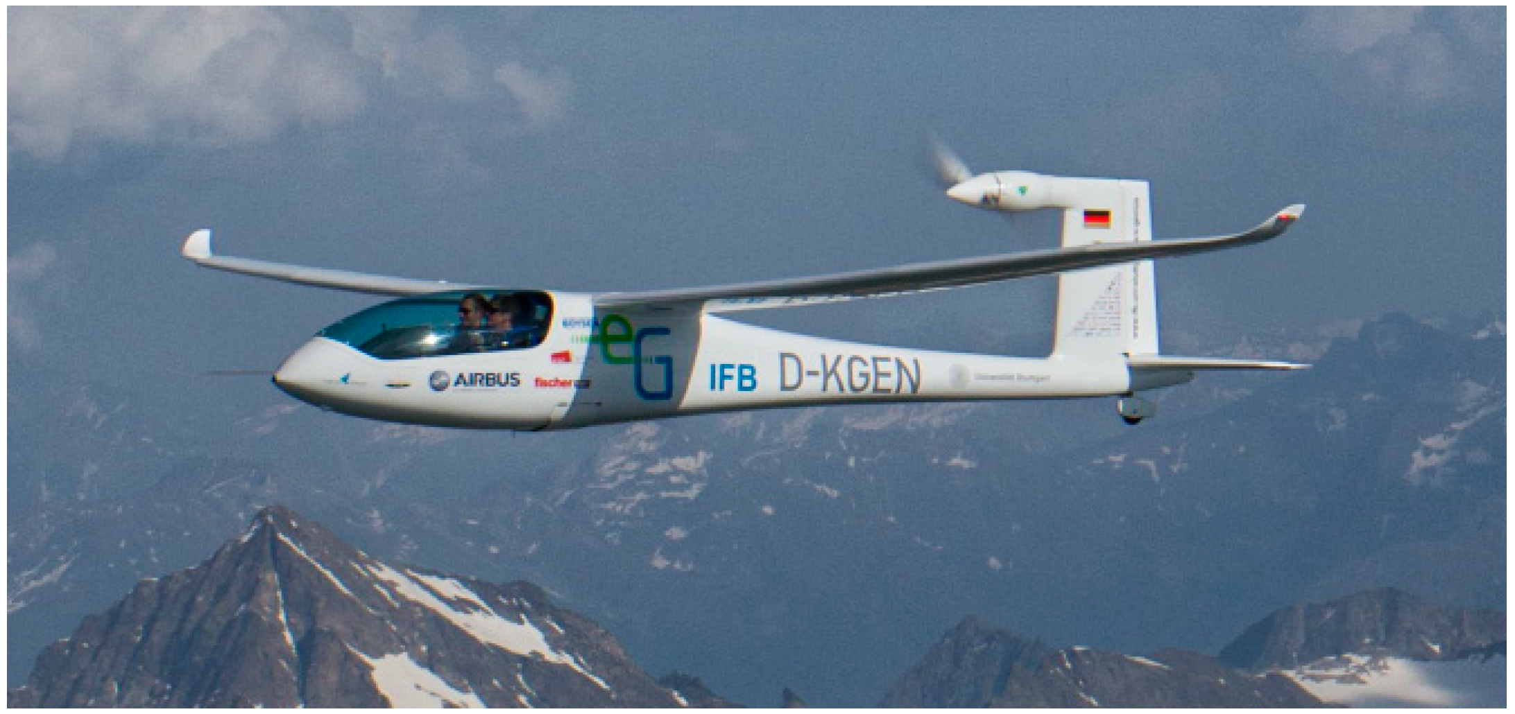
E-Genius is a two seat full electric motor glider. The full-scale e-Genius is a manned technology test aircraft. E-Genius in Figure 1 is built to demonstrate the competitiveness of electrical propulsion over conventional propulsion systems in aviation. It has a wingspan of 16.9 m and a maximum take-off mass of 950 kg. The electric power train allows a maximum range of more than 400 km.
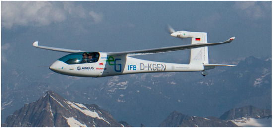
Figure 1.
e-Genius (University of Stuttgart, Institute of Aircraft Design).
The model e-Genius-Mod is prepared as a technology test bed to demonstrate new technologies for future aircraft design in relevant environment. The UAS test bed will be used for academic and innovative research projects to demonstrate new technologies up to TRL6. The design of the test bed is initially prepared for the investigation of new aircraft configuration solutions for distributed electric propulsion systems.
Once the similarity requirements between the scaled model and the full scale aircraft are identified, the model is a pre-test bed for the full-scale aircraft. Results like improved performance can be collected and the most promising concept can be identified for full-scale integration.
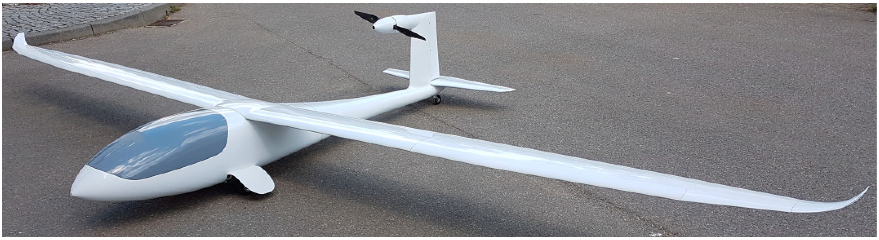
The free-flight platform e-Genius-Mod (Figure 2) is a 33.3% scale model of the e-Genius, scaled in compliance with the similarity conditions of Froude number and Reynolds number as a free flight model [3]. The model is prepared as a technology test bed to demonstrate new technologies for future aircraft design in relevant environment. The UAS test bed will be used for academic and innovative research projects to investigate scaling similarities of free flight models and to demonstrate new technologies up to TRL6. The design of the test bed is primarily prepared for the investigation of new aircraft configuration solutions for distributed electric propulsion systems.

Figure 2.
e-Genius-Mod 33.3% free-flight model.
The test bed e-Genius-Mod will be an extension of the full-scale aircraft for further investigation of electrical flight. Electrical propulsion systems provide new degrees of freedom for aircraft design with respect to propulsion integration. To investigate and demonstrate these innovations, a flexible test bed like the unmanned scale model is required. The demonstration of innovative concepts like distributed propulsion on a manned aircraft is expensive and time intensive and not suitable for research with unknown outcomes. With its modular airframe design the e-Genius-Mod is the basis for an efficient and systematic research of the various effects of distributed propulsion.
2.1. Scaling
To realize an efficient test bed, scaling relationships and similarity requirements have to be adhered to [8,9]. To get reliable flight data from the free flight test with a model aircraft the following aspects must be respected for scaling:
- Dimensions
- Aerodynamics
- Inertia
Scaling of the e-Genius-Mod followed the scientific findings of NASA Technical Paper 1435 “Similitude Requirements and Scaling Relationships as Applied to Model Testing” [3]. Dimension and inertia scaling follow the similarity criteria of Froude number [3,10].
Aspects of aerodynamic scaling must mainly respect the Reynolds number. With respect of the conditions for similarity of Froude number the following equation for the Reynolds number is fulfilled [3]:
Airfoil of the wing and aerodynamic surfaces has to be proven with respect to their effectiveness while scaling under Froude number.
2.1.1. Scaling Factor
The scaling factor is a key factor for the usefulness of the UAS test bed. Several aspects must be considered for the identification of the matching scale factor:
- Flight conditions and test area
- Handling and transportability
- Environmental influences
- Payload test equipment
- Scalability of new technologies which shall be investigated
Furthermore, a big advantage of the e-Genius is its dimension of a general aviation aircraft, which allows a small scaling factor. It is assumed that the error influence increases with increasing scaling factor. The larger this error is in the overall scaling of all the variables relevant for flight test, the lower the transferability of results from a scale model to its full-scale equivalent is estimated. By determining the scale factor, previous research results must be taken into account, which show that similarity of Reynolds number cannot be met for free-flight models [9]. Based on this knowledge, when considering the Reynolds number of the model, it was taken into account that it does not lie within the critical range of Reynolds numbers for the selected scaling factor. To obtain the longest possible attached air flow, the Reynolds number is in the supercritical range. For the e-Genius-Mod the following scaling factor and Reynolds number are chosen [11]:
The Reynolds number of the model of 467.948 (operating altitude 300 m) has to be seen alongside a Reynolds number for the full-scale aircraft of 2057088 (operating altitude 2000 m) [11]. This means an error of 22.7% for the Reynolds number must be taken into account in further designs.
2.1.2. Airfoil Scaling
As opposed to the geometric scale of the full-scale aircraft, the airfoil of the main wing cannot be scaled geometrically without influencing the flight characteristics as the Reynolds number cannot be met. To ensure the model airplane to have the same flight properties, the fundamental dimensionless quantities of the main wing should not have too large of deviations [12]. Otherwise flight performance tests of the model cannot deliver valid results for investigating scaling laws as a technical basis comparing the full-scale and the scale model of the e-Genius and other airplanes.
The most important dimensionless quantity describing the properties of an airfoil of the wing is the Reynolds number. It characterizes the flow formation in the boundary layer. Due to the differences in flight altitude of the scale model, speed and geometric scale of the depth of the sash airfoil the Reynolds number cannot be met. This manifests itself by different transition spot positions, where laminar flow switches to turbulent.
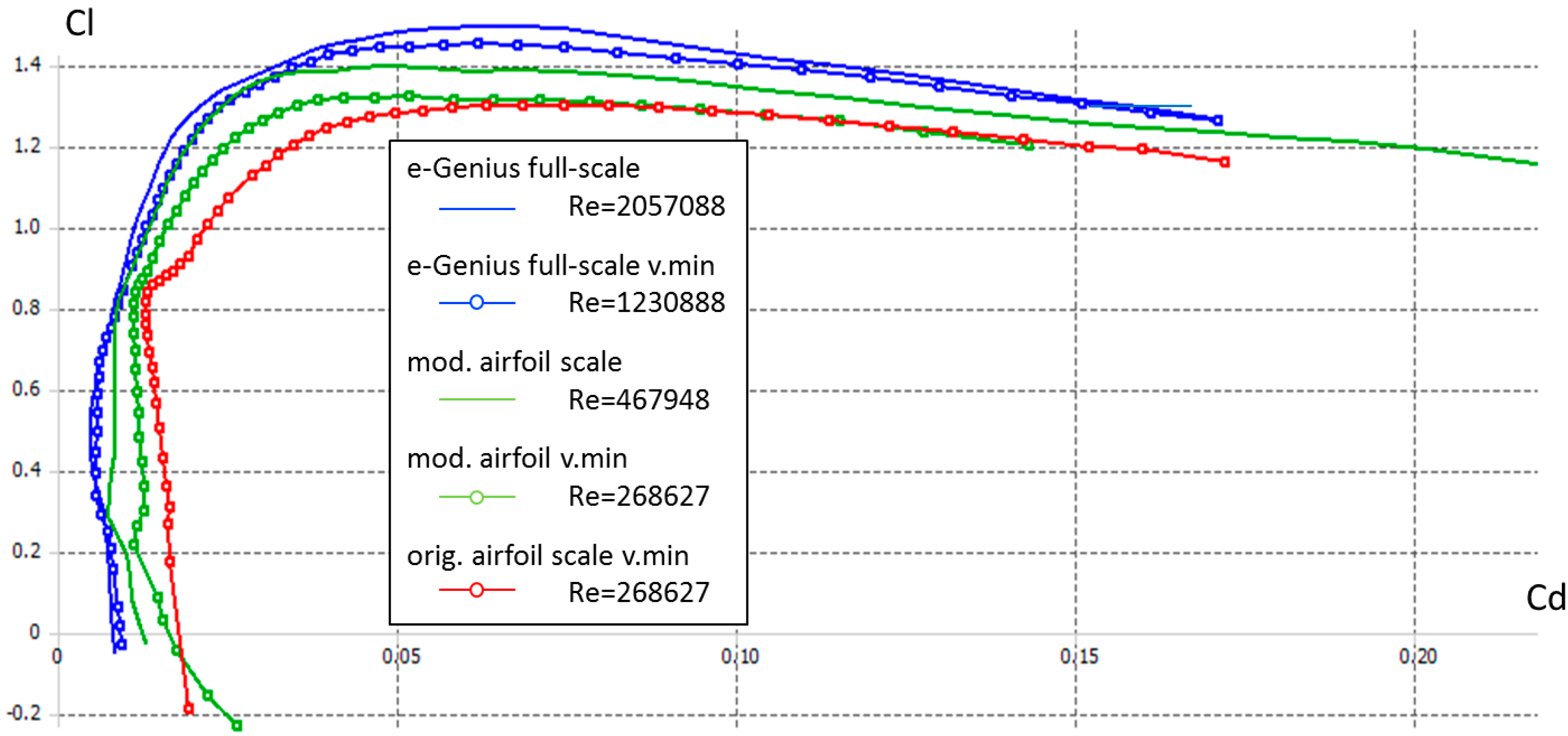
The unavoidable deviations of some dimensionless quantities such as the Reynolds number result in massive deviations comparing the polar curves from full-scale and scaled aircraft. The main goal is to ensure the same flight characteristics by creating adherence of the polar curves from the full-scale and scaled aircraft [11,13]. An effective approach to this problem is made by doing some geometrical modifications of the airfoil. The following parameters are modified:
- Thickness / chord ratio
- Airfoil camber
- Location of maximum thickness
- Location of maximum chamber
- Leading edge radius
To reduce the complexity of the wing with its different segments the wing panel is reduced to an airfoil with constant chord, constant thickness and no twist. The primary focus is on the flight performance which is characterized by the flight condition achieving maximum range. To align the polar curves of scaled and full-scale airfoils the angle of attack for the flight at maximum range has to be determined.
The given design velocity of the e-Genius is 43.056 m/s [11]. The scaled velocity can be calculated under similarity of the Froude number for free-flying models [3,9], as the flight conditions of full-scale and scaled e-Genius are always under incompressible flow. “For incompressible flow, the kinematic properties are preserved by using velocities scaled from Froude number similitude requirements (Froude scaling).” [3] (p. 2).
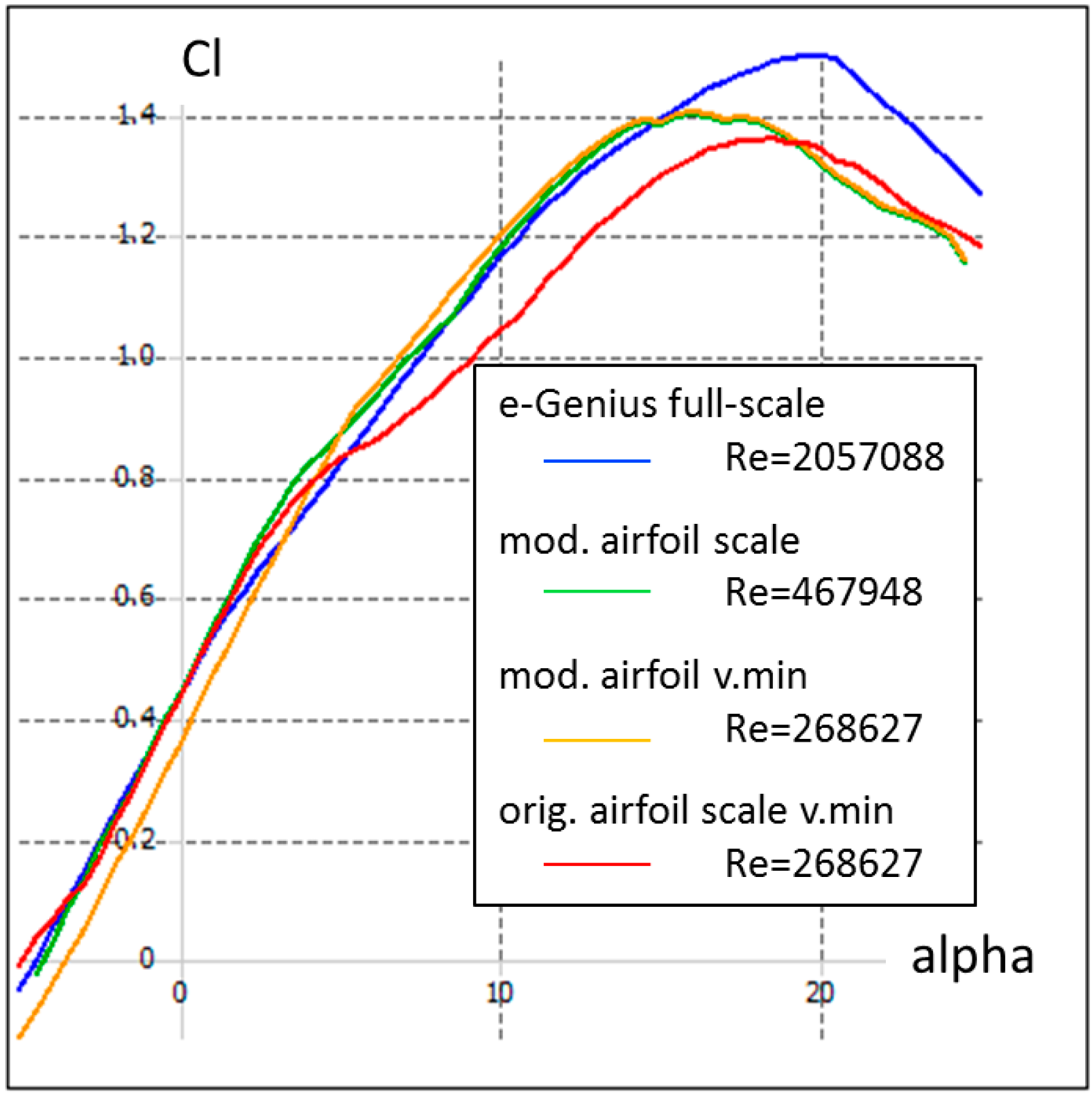
Equation (3) leads into a scaled velocity of the scale model of 24.858 m/s. Substituting the velocity into the lift equations in horizontal flight leads to the lift coefficient. Marking the lift coefficient in the polar curves of the airfoil calculated using X-foil as aerodynamic tool supplies the desired value for the angle of attack (α = 3.5°). The following development of the airfoil of the scaled aircraft is made, regarding the best possible conformity in the area near to an angle of attack of 3.5°, as further investigations focus on cruise flight conditions.
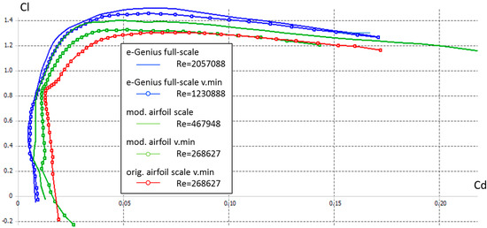
Regarding the polar curve of both the scaled and the full-scale e-Genius, the laminar area of the curve of the scaled model is way more differentiated and has wider dimensions. In general the curve is displaced towards higher drag coefficients. Both on the upper and on the lower side of the airfoil the transition from laminar to turbulent flow in the boundary layer takes place later towards the trailing edge. The moment coefficients of scaled and full-scale airfoil are nearly similar, the value of the model being slightly smaller [11].
To correct the form of the laminar area, the thickness/chord ratio is reduced significantly [13]. The earlier occurring suction peak at the upper boundary of airfoil of the wing displaces the transition spot towards the leading edge and reduces the width of the laminar area of the polar curve.
The airfoil camber is reduced to reduce the slightly increased level of the lift coefficient, which also moves the laminar area in direction of the laminar section of the full-scale. The movement of the location of maximum chamber towards the leading edge moves the spot of transition in the same direction. It is important to check the effect of any geometrical change on the angle of attack where no lift occurs. Any changes in that angle result in a change of the velocity of maximum range.
To compensate for the negative effect of a thickness reduction of the airfoil with respect to stalling behavior, the location of maximum thickness is moved towards the leading edge. The risk of uncontrolled flow separation in the boundary layer is reduced by the homogenization of the pressure coefficient in the rear of the airfoil. In addition, the level of the drag coefficient is reduced in the turbulent areas of the polar curve and helps to assimilate the curves of full-scale and scaled e-Genius-Mod.
The polar curves of the model are adapted to those of the original by stepwise manual adjustment of the modifications listed above.
The installation of tabulators delivers good results to optimize the length of laminar flow sections regarding the prioritized flight condition of maximum range. They ensure the transition from laminar to turbulent flow in the boundary layer exactly is in the right place creating a flow formation around the airfoil very similar to that of the original aircraft. However, the losses of laminar flow areas at different angles of attack have to be taken into account creating higher drag in other flight conditions.
To ensure sufficiently good flight characteristics beside the flight performance tests, the following flight conditions require closer examination [11,12,13]:
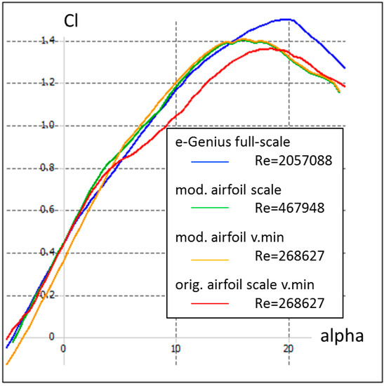
The main issue regarding high angles of attack is the decreasing lift coefficient beyond the laminar areas of the polar curve and the early stall of the original full-scale airfoil. Reducing thickness and camber as well as moving the location of maximum thickness towards the leading edge aligns the curves of the scaled and the full-scale aircraft up to an angle of attack of 16°.
The required lift coefficients calculated using the lift equation are being compared with those from the polar curves to verify the ability of holding altitude at the scaled minimum velocity using the modified airfoil. Although the required lift cannot be created, the polar curves of the modified airfoil align much better to those of the full scale aircraft compared to the original one. The occurring error in the achieved landing velocity is 19% [11].
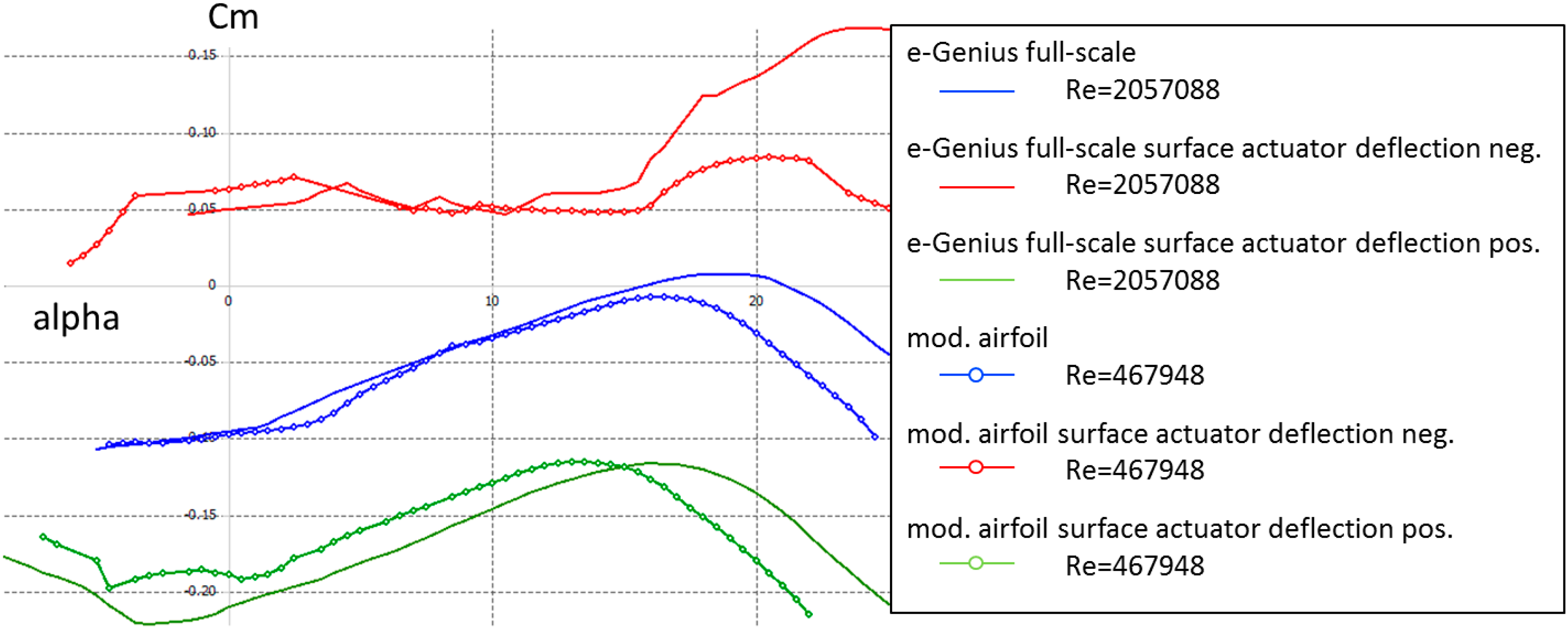
The curve progression of the moment coefficient at different states of surface actuators deflection is examined to ensure the maneuverability (Figure 5) of the scaled aircraft. All in all the responses in all flight conditions are nearly identical, only at very high angles of attack and low speed the effects of the surface actuators are apparently smaller.
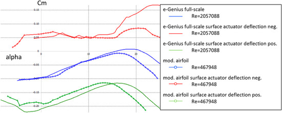
Figure 5.
Insurance of the maneuverability - full-scale vs. scale airfoil [11].
Figure 6 shows the full-scale and the scaled airfoil which allows inflight investigations at cruise speed with similarity requirements. The technical data of the airfoils are shown in Table 1.
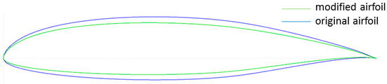
Figure 6.
Geometrical change of the airfoil [11].

Table 1.
Airfoil data full-scale vs. scale [11].
2.1.3. Variable Pitch Propeller
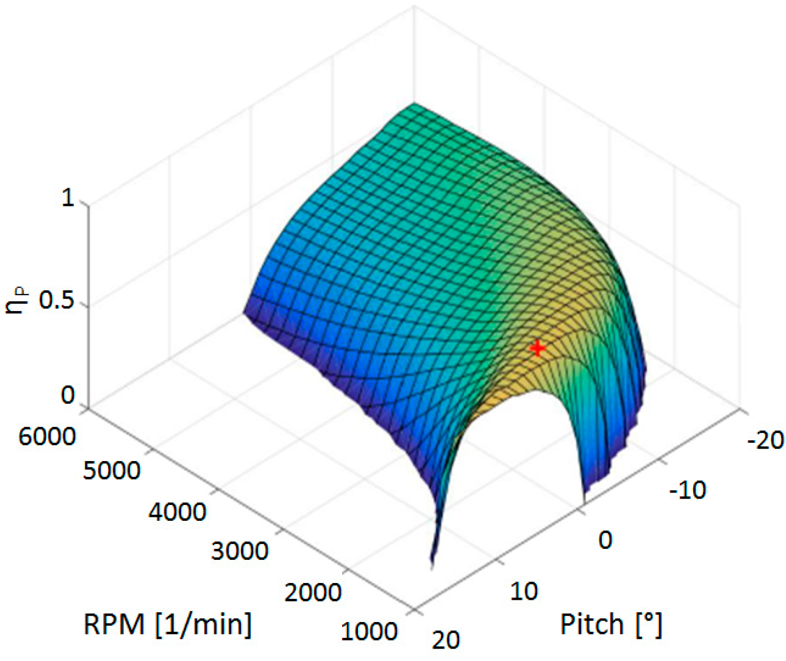
In order to model several flight conditions in a realistic way with respect to the propulsion system, the scaled e-Genius-Mod is fitted with a constant speed propeller system. Hereby it is possible to operate the model in its optimal operating points, for example during climb or cruise (Figure 7). A variable pitch propeller allows operating the propulsion components in the point of their maximum point of efficiency.

Figure 7.
Propeller efficiency at 17 m/s (true air speed) [14].
To stay close to the original, a variable pitch propeller (VPP) has also been developed specifically for the scaled model [14]. Due to the relative rarity of variable pitch propellers for UAS of this size, it was decided to conduct a study on the e-Genius-Mod propeller system to compare it with the fixed propeller, and to determine the optimal settings for different flight situations. The overall goal is to gather information to optimize the operation of the propeller system.
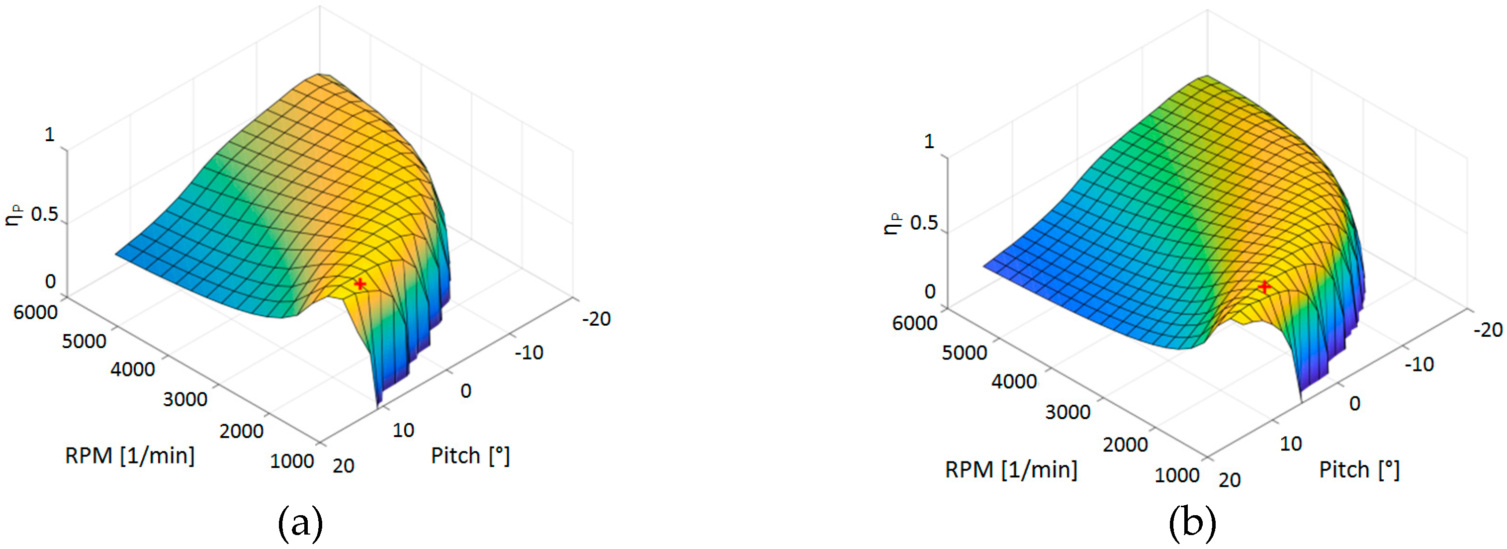
For this purpose, a simulation program based on blade-element theory was set up in Matlab [14]. To obtain the geometrical data needed for the calculations in a nondestructive way, an image-based process is used [15] to extract the angle of incidence and chord as functions of the radius. The program could then be used to compute the propeller performance as a function of flight speed pitch and RPM, and plot this data in 2D or 3D charts. Furthermore, an optimization algorithm is implemented to find the best settings in different situations.
As expected, the program allowed to get a good insight in the performance that can be expected from the e-Genius powertrain and the resulting flight performance, for the variable-pitch as well as the fixed-pitch propeller. The results permitted to draw very interesting conclusions:
- The fixed propeller can efficiently cover a large portion of the flight envelope. In cruise flight (best range or best endurance), the fixed propeller works very close to its optimum, and the VPP barely gives any performance improvement (less than 2%). This is due to the e-Genius being a 33.3% scaled model, and having a smaller flight envelope than that of a full-scale aircraft.
- During climbing flight, the VPP improves performance by approximately 25%. However, the e-Genius-Mod, being a UAS, will mostly fly at low altitude (<500m). Consequently, climbing will be very short when compared to the cruise flight, thus limiting the performance improvement.
- The electric engine has a very good efficiency over a wide range of RPM, therefore the advantage of running the engine near its point of best efficiency (the way it would be done on a piston-engine aircraft) does not translate to the e-Genius model.
- The pitch variation system itself weighs 400 g, and due to its position at the aft of the fuselage this weight needs to be counterbalanced in the nose to keep a neutral center of gravity. Consequently, the overall weight penalty ranges from 400 to 1200 g (depending if the payload itself can be used as ballast to counterbalance this without adding overall weight, but this may not always be possible). Therefore, in most flight situations the increased weight of the variable-pitch propeller might negate the possible performance improvements.
In certain situations however, it could be useful to install a VPP:
- If the runway is particularly short, take-off performance can be noticeably improved.
- If the flight tasks require flying at either very low or very high speeds, outside the range where the fixed propeller performs well.
Therefore the decision to install the system or not should be taken after careful analysis of the future flight task and operating conditions. The results (Figure 8) highlight how the intended flight task of an aircraft, as well as the characteristics of its powertrain influences the usefulness of a variable-pitch propeller.
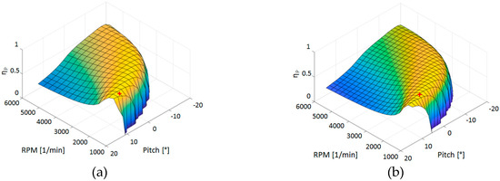
Figure 8.
VVP for max range (a) and max duration (b) [14].
3. Results
With e-Genius-Mod a flexible test platform is realized which can be perfectly used for flight testing focused at academic research. The platform covers different fields of future research at the Institute of Aircraft Design at University of Stuttgart. Thanks to the design under similarity requirements it is an investigation platform for free flight models used as a tool in aircraft design.
Through its modular design new technologies can be tested with small, fast and low cost changes on the aircraft. The modular design allows changes while maintaining the baseline system design. In this way new research projects can focus on technology assessment in flight. With the platform a technology demonstration in relevant environment is partially possible.
Furthermore, the high payload capacity (Table 2) combined with a large free volume within the airframe allow an easy integration of system technologies and in flight experiments.
Table 2.
Technical Data of e-Genius-Mod [11].
3.1. Flexible Airframe Configuration
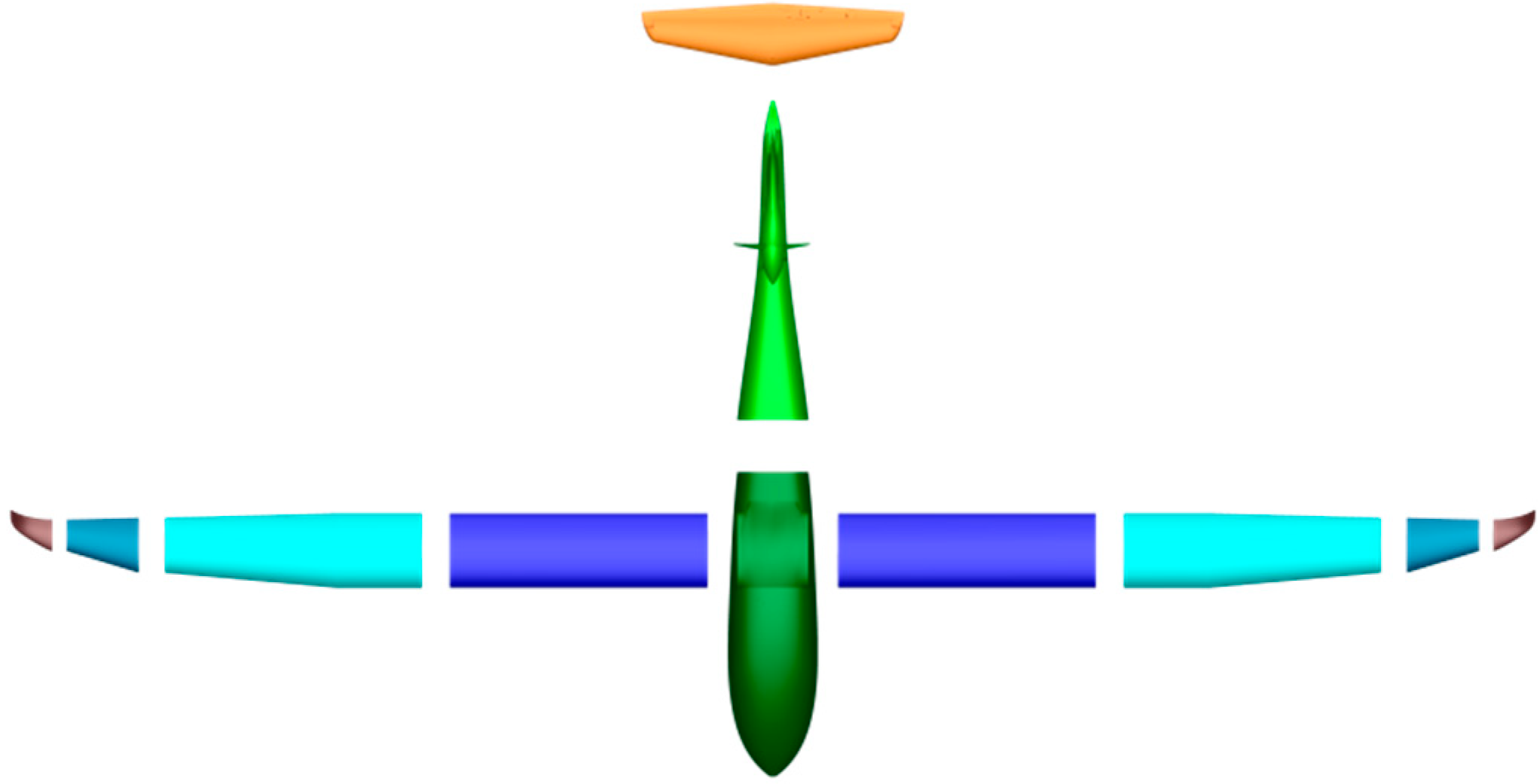
The e-Genius-Mod airframe parts are divided in segments (Figure 9), leading to multiple advantages. One aspect is the transportability of the aircraft system, which allows the integration and maintenance of the technology to be tested in the lab while being mobile enough to use different airfields for flight testing.
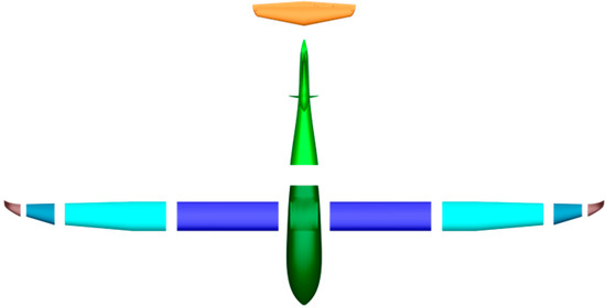
Figure 9.
Segment overview e-Genius-Mod.
Furthermore, the segmentation enables the realization of drastic changes to the aircraft configuration. For example, new wings/airfoils can be tested without making changes to the fuselage segment. Another conceivable change in the configuration is the use of a modified tail segment that would allow for example an easy and fast assessment of a V-tail. In this case, only the tail segment would have to be replaced.
This was the motivation to divide this fuselage in two parts and an elevator. The wing consists of eight individual segments. Each wing half is assembled of two main segments which include the control surfaces, an outer surface to increase the aspect ratio and the winglet as wing tip. The segments have connection interfaces for data and power transmission.
3.2. Systems Design
The flight system of the e-Genius-Mod is designed for remote-controlled (RC) flight as well as automatic flight. The main part of the e-Genius-Mod is the flight management system, realized with a Pixhawk autopilot.
Complete radio coverage between pilot and aircraft, through all flight attitudes is guaranteed via two RC receivers with two antennas, at any time. Three antennas are installed around a fuselage section with an offset of 120° and one antenna is oriented lengthwise of the fuselage.
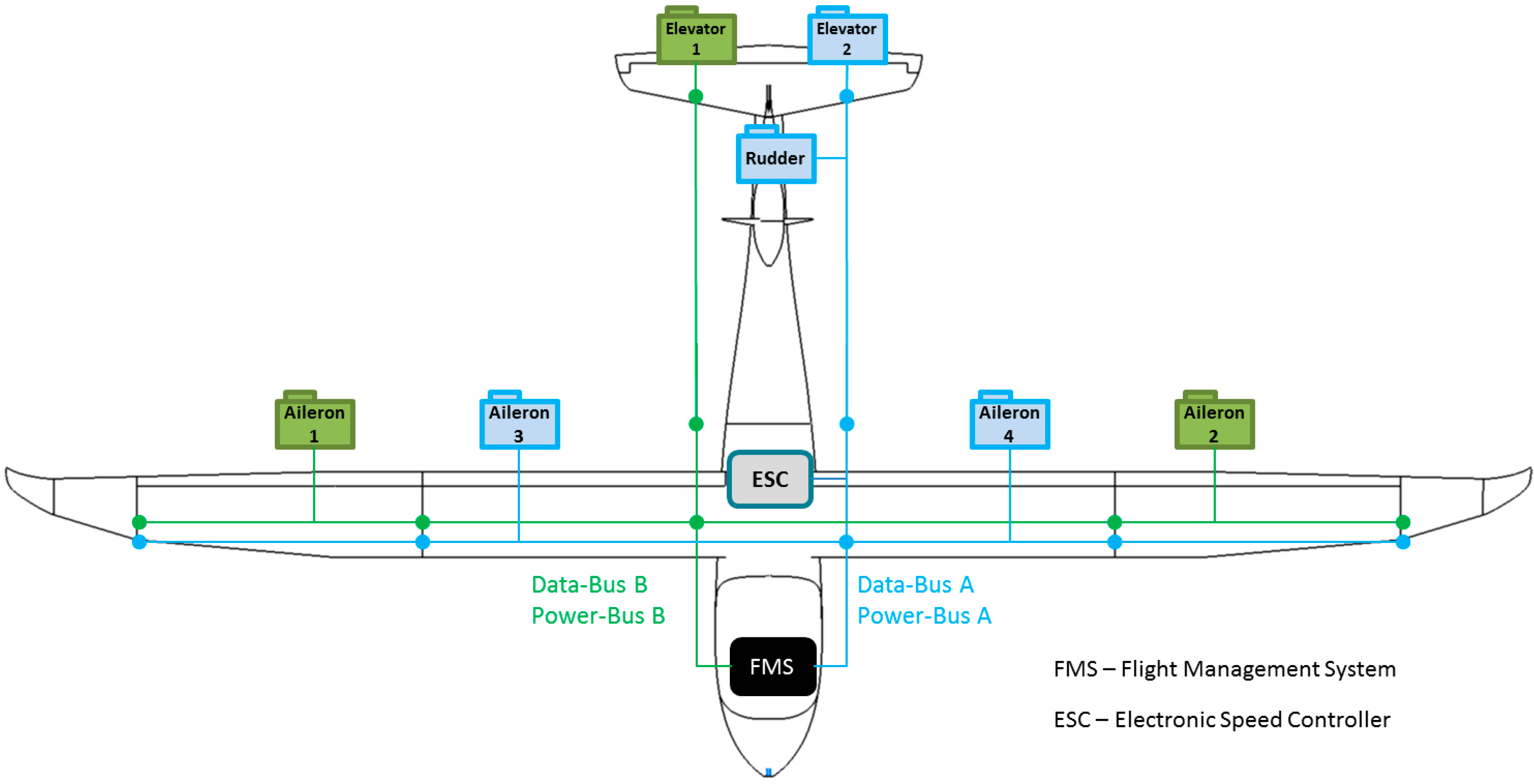
For fail safe reasons each segment of e-Genius-Mod (Figure 10) is connected with two buses of the flight management system to ensure redundancy. E-Genius-Mod has two separate data buses and two power buses. The power buses are realized with a Powerbox-System which is connected to two batteries for a redundant power supply. As a result, no single failure in the power supply system leads to a loss of the aircraft.

Figure 10.
System overview e-Genius-Mod.
Even if one of the two data bus-systems failed, the actuators are distributed on both bus systems according to the following schematic, which still allows a sufficient control authority over the aircraft:
The full-scale e-Genius is designed with flaperons. These control surfaces are divided for the e-Genius-Mod. In doing so, smaller actuators can be used and the system reliability against failure of an activator is improved. Furthermore there is the advantage to use the outer surface as outboard aileron and the inner as inboard aileron and flap. The flaperon is only needed for investigation in cases where similarity conditions between scaled and full-scale e-Genius are necessary.
The shown connection has the advantage that the aircraft remains controllable even with only one bus system available. By losing bus A the outboard ailerons and one control surface of the elevator are still available. In case bus B is lost the inboard ailerons/flaps, one control surface of the elevator and the rudder are available. Because the effectiveness of the inboard ailerons is lower compared to the outboard ailerons, the inboard ailerons are connected on the same bus as the rudder. This way both failure cases guaranty sufficient controllability.
A failure of the electronic speed controller and the electrical motor is defined as noncritical because the e-Genius-Mod can fly as sailplane due to its high aspect ratio.
3.3. Free–Flight Model e-Genius Mod
Future research of the e-Genius-Mod is focusing on investigation of new aviation technologies, configurations, and similarity requirements. Therefore it is equipped as “free flight wind tunnel”. The standard integrated measuring equipment allows a complete data collection for identifying the aircraft performance. Difficulties in free-flying measurements, however, are the uncontrollable environmental conditions, which can influence the results of the flight tests. In order to keep the disturbance as low as possible, the scaling factor of the e-Genius-Mod is sufficiently low.
The standard set of measurement data consists of the basic data required for the flight control and additional measured values to support the flight control system, as well as input data for the ground station. The main sensors are:
- Inertial measurement unit—data of flight attitude (angle of orientation, acceleration, rotation rate)
- Air data boom—angle of attack, side slip, static and dynamic pressure
- GPS—position of the aircraft
- Actuator feedback—control surface angle
- Monitoring sensors—battery current/voltage/temperature, engine RPM/temperature
Due to the internal volume of the e-Genius-Mod, additional systems for data acquisition can be implemented as required to generate the optimal data set, depending on the in-flight experiment.
3.4. Application Example—Investigation of a Wing Tip Propulsion System
As stated before, the flexibility of the UAS test bed and its modular design is well suited for investigation and demonstration platform for distributed propulsion systems. In a first step, a wing tip propeller will be investigated in the project ELFLEAN (Electric wing tip propulsion system for the development of energy-efficient and noise reduced airplanes), supported by Federal Ministry for Economic Affairs and Energy on the basis of a decision by the German Bundestag.
One aspect of the project is to test the wing tip propulsion system in flight on the UAS test bed e-Genius-Mod. For a more efficient investigation of the effects of wing tip propulsion, the aspect ratio of the UAS shall be reduced to increase induced drag.
Through the modular concept these requirements can easily be fulfilled. As shown in Figure 11, the outer segments of the wing can be disconnected to have a ready to fly reference configuration for the investigation.
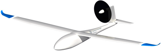
Figure 11.
e-Genius-Mod with disconnecting wing tips to reduce aspect ratio.
Also, the connection of the wing tip propulsion system can be realized (Figure 12) with only one new lay-up mold for the pods of the system. An interface to connect the pods to the structure and the flight management system is already available on the shortened end of the wing.
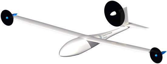
Figure 12.
e-Genius-Mod with integrated wing tip propulsion system.
4. Discussion
With the platform e-Genius-Mod a tool is available at the University of Stuttgart. For technology improvements at the full-scale, its scale is a perfect test platform. Because of its modular construction e-Genius-Mod it is an ideal tool to integrate and to test new technologies in-flight.
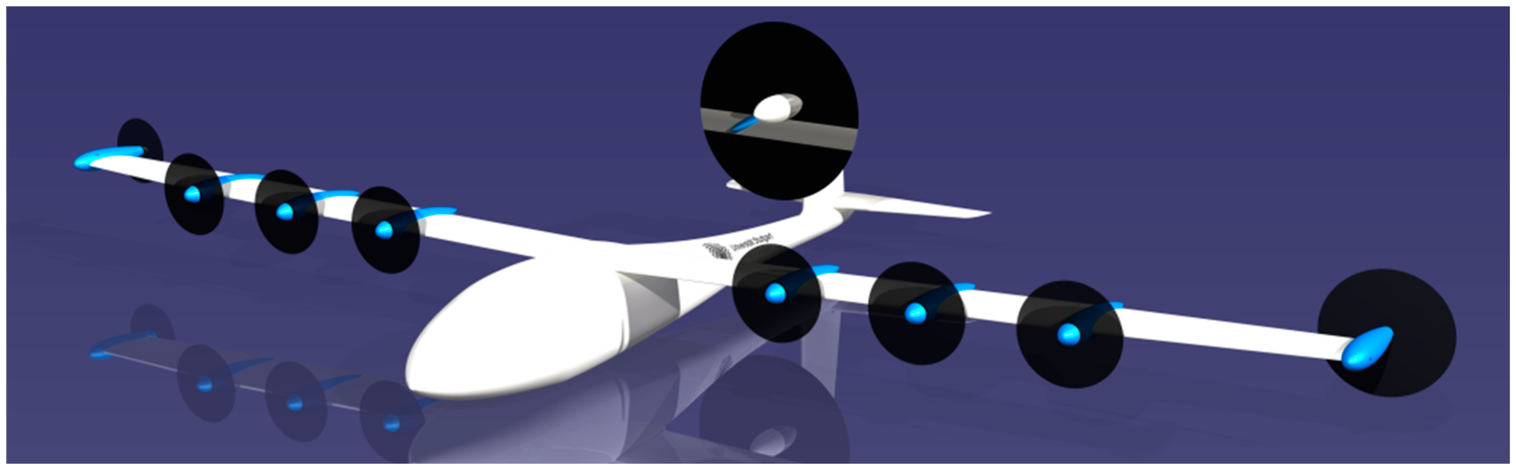
The UAS test platform e-Genius-Mod currently is used to test and validate various effects of distributed propulsion (Figure 13). Beyond this, it is planned to use the platform for all kinds of technologies, such as structural concepts, acoustical analysis, flight guidance and navigation or data transmission technologies. This will further demonstrate the value of modular and versatile UAS platforms for the early, safe and cost effective flight testing of innovative technologies and concepts.
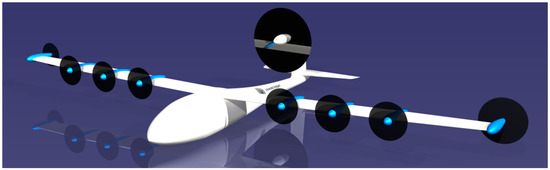
Figure 13.
Design study “Investigation of distributed propulsion”.
5. Conclusions
The e-Genius-Mod as a free-flight demonstrator creates excellent opportunities for flight and system testing as well as the investigation of new aircraft configurations in terms of feasibility. Through its development in respect of Froude number e-Genius-Mod has the advantage of the comparability with its original model, system laws for flight mechanical and dynamical behaviors can be improved. Its modular design makes it possible to test different configurations and new aviation technologies (like new propulsion systems) time and cost efficiently. The unmanned aerial system e-Genius-Mod is a handsome tool to close the gap between upstream research and flight demonstration to reach a higher technical readiness level. For the Institute of Aircraft Design at University of Stuttgart, the system is a game changing advanced tool to test new aviation technologies and to expand the results of research and development tools like wind tunnel tests and CFD calculations.
Author Contributions
Conceptualization, D.P.B.; airfoil scaling, A.B.; variable pitch propeller, L.K.; writing—original draft preparation, D.P.B.; writing—review and editing, D.P.B., J.D., A.S.; supervision, A.S.; project administration, D.P.B.
Funding
This research received no external funding.
Conflicts of Interest
The authors declare no conflict of interest.
References
- Bergmann, D.; Denzel, J.; Strohmayer, A. UAS as flexible and innovative test platform for aircraft configuration and systems testing. In Proceedings of the 8th EASN-CEAS International Workshop on Manufacturing for Growth & Innovation, Glasgow, UK, 4–7 September 2018. [Google Scholar]
- Kittmann, K. Entwicklung einer modularen Messplattform zur Analyse des Potenzials von Freiflugmessungen. Ph.D. Thesis, University of Stuttgart, Institute of Aircraft Design, Stuttgart, Germany, 2013. [Google Scholar] [CrossRef]
- Wolowicz, C.H.; Bowman, J.S., Jr.; Gilbert, W.P. Similitude Requirements and Scaling Relationships as Applied to Model Testing; NASA Technical Paper 1435; National Aeronautics and Space Administration, Scientific and Technical Information Branch: Washington, DC, USA, 1979. [Google Scholar]
- European Commission; Directorate-General for Research and Innovation; Directorate General for Mobility and Transport. Flightpath 2050 Europe’s Vision for Aviation, Report of the High Level Group on Aviation Research; Publications Office of the European Union, European Union: Luxembourg, 2011; ISBN 978-92-79-19724-6. [Google Scholar] [CrossRef]
- IATA Technology Roadmap 2013, 4th Edition. 2013. Available online: https://www.iata.org/whatwedo/environment/Documents/technology-roadmap-2013.pdf (accessed on 30 November 2018).
- Schmollgruber, P.; Gobert, J.-L.; Gall, P.-E.; Goraj, Z.; Jentink, H.W.; Näs, A.; Voit-Nitschmann, R. An innovative evaluation platform for new aircraft concepts. Aeronautical J. 2010, 114, 451–456. [Google Scholar]
- Jordan, T.; Langford, W.; Hill, J. Airborne Subscale Transport Aircraft Research Testbed—Aircraft Model Development. In Proceedings of the AIAA Guidance, Navigation, and Control Conference and Exhibit, San Francisco, CA, USA, 15–18 August 2005. [Google Scholar] [CrossRef]
- Jouannet, C.; Lundström, D.; Amadori, K.; Berry, P. Design of a Very Light Jet and a Dynamically Scaled Demonstrator. In Proceedings of the 46th AIAA Aerospace Sciences Meeting and Exhibit, Reno, NV, USA, 7–8 January 2008. [Google Scholar] [CrossRef]
- Chambers, J.R. Modeling Flight, The Role of Scaled Free-Flight Models in Support of NASA’s Aerospace Programs; NASA Technical Report, National Aeronautics and Space Administration; NASA Headquarters: Washington, DC, UAS, 2010; ISBN 978-0-16-084633-5. [Google Scholar]
- Nguewo, D. Erstellung und Optimierung der Skalierungsgesetze zur Abschätzung der Aerodynamik und der Eigendynamik eines Flugzeugs auf der Basis von frei fliegenden Modellen. Ph.D. Thesis, University of Stuttgart, Institute of Aircraft Design, Stuttgart, Germany, 2007. [Google Scholar] [CrossRef]
- Baden, A. Entwurf eines Freiflugmodells des E-Motorseglers e-Genius unter Berücksichtigung der aerodynamischen Vergleichbarkeit. Bachelor’s Thesis, University of Stuttgart, Institute of Aircraft Design, Stuttgart, Germany, 2016. [Google Scholar]
- van Gorcum, J.J. Ready for Take-off: Scaled Flight Testing—An investigation into influence of scaling on the aerodynamic properties. Master’s Thesis, Delft University of Technology, Delft, The Netherlands, 2017. [Google Scholar]
- Lutz, T. Profilentwurf, Skript zur Vorlesung und Seminar; Lecture Notes; University of Stuttgart, Institute of Aerodynamics and Gas Dynamics: Stuttgart, Germany, 2007. [Google Scholar]
- Kugler, L. Analysis and characterization of the variable pitch propeller for the Scaled-down e-Genius. Bachelor’s Thesis, University of Stuttgart, Institute of Aircraft Design, Stuttgart, Germany, 2018. [Google Scholar]
- McCrink, M.H.; Gregory, J.W. Blade Element Momentum Modeling of Low-Re Small UAS Electric Propulsion Systems. In Proceedings of the 33rd AIAA Applied Aerodynamics Conference, Dallas, TX, USA, 22–26 June 2015. [Google Scholar] [CrossRef]


© 2019 by the authors. Licensee MDPI, Basel, Switzerland. This article is an open access article distributed under the terms and conditions of the Creative Commons Attribution (CC BY) license (http://creativecommons.org/licenses/by/4.0/).