Article

Online Flatness Detection Method and Experimental Research of Aircraft Rudder Surface Based on Bidirectionally Coupled PSO-SA Hybrid Optimization Algorithm

1
School of Mechanical Engineering, Hebei University of Technology, Tianjin 300130, China
2
Key Laboratory of Hebei Province on Scale-Span Intelligent Equipment Technology, Hebei University of Technology, Tianjin 300130, China
3
Information Research Institute (Tianjin Agricultural Science and Technology Library), Tianjin Academy of Agricultural Sciences, Tianjin 300130, China
*
Author to whom correspondence should be addressed.
Aerospace 2026, 13(8), 671; https://doi.org/10.3390/aerospace13080671
Submission received: 26 May 2026 / Revised: 3 July 2026 / Accepted: 22 July 2026 / Published: 27 July 2026
(This article belongs to the Section Aeronautics)

Abstract

Online flatness detection of aircraft rudder surfaces serves as a pivotal core procedure for ensuring the manufacturing precision, aerodynamic performance and operational safety of aeronautical components. Traditional plane fitting-based detection approaches are constrained by low detection efficiency, susceptibility to local optimal solutions, weak anti-noise robustness and limited automation capability, which fail to satisfy the micron-level high-precision online detection requirements for curved composite rudder surfaces in batch manufacturing scenarios. To address the aforementioned technical bottlenecks, this study proposes a bidirectionally coupled PSO-SA hybrid optimization algorithm for non-convex minimum zone flatness evaluation of curved rudder surfaces, which overcomes the unidirectional open-loop iteration limitation inherent in conventional serial PSO-SA composite frameworks. Two targeted algorithmic improvements are elaborated in this work: a residual-adaptive nonlinear inertia weight strategy, which dynamically balances global exploration and local exploitation capabilities based on the fluctuation characteristics of free-form surface measurement residuals; and a measurement noise-modified Metropolis acceptance criterion, which substantially enhances the algorithm’s anti-interference performance against on-machine trigger sampling noise. Integrating with the trigger-type on-machine detection hardware of computer numerical control (CNC) machine tools, an integrated online detection system is established to realize the full-process functions of point cloud data acquisition, error compensation, intelligent plane fitting and flatness error evaluation. Meanwhile, the complete technical workflow involving measurement path planning, probe calibration and algorithm iterative solution is systematically illustrated. Comparative simulation experiments implemented on the MATLAB platform demonstrate that the proposed algorithm exhibits superior performance in convergence speed, fitting accuracy and optimization stability over five mainstream algorithms, including standard particle swarm optimization (PSO), standard simulated annealing (SA), comprehensive learning PSO (CLPSO), adaptive cooling SA and conventional serial PSO-SA. On-machine physical measurement experiments are conducted on 24 aircraft rudder workpieces covering aluminum alloy skins and assembled riveted components. After multi-dimensional systematic calibration, the overall detection error of the developed system is controlled within 1 μm. The experimental results indicate that the average flatness error calculated by the proposed bidirectionally coupled PSO-SA algorithm is 29.7 μm, which is 30.1% and 38.5% lower than that of standard PSO and standard SA, respectively, fully complying with the aviation flatness tolerance specification of 0.1–0.3 mm. Moreover, the full detection cycle for a single workpiece is only 2.1 min, achieving a 34.4% reduction in detection time compared with standard PSO and effectively improving the efficiency of online in-process inspection. One-way analysis of variance (ANOVA) combined with Tukey’s posthoc test further verifies that the accuracy superiority of the proposed algorithm is statistically significant. This research provides a targeted theoretical basis and complete engineering implementation scheme for intelligent flatness detection of aerospace curved thin-walled parts, and offers a valuable technical reference for form and position error evaluation of irregular industrial components under noisy measurement conditions.

1. Introduction

Aircraft control surfaces are critical aerodynamic load-bearing and maneuver-regulation components for aerospace vehicles. Flatness serves as a vital form error indicator that directly governs the assembly precision, aerodynamic performance and flight safety of aircraft structures [1]. High-precision and high-efficiency online flatness detection for control surfaces has therefore become an indispensable procedural link in standardized intelligent aerospace manufacturing systems. Currently, mainstream flatness detection techniques for aerospace components can be classified into contact and non-contact detection categories [2]. Traditional contact detection methods employ dial indicators and dedicated measuring fixtures to conduct discrete point sampling on control surfaces, which suffers from prominent limitations including heavy reliance on manual operation, low sampling density, prolonged detection cycles and secondary surface wear. Such methods are only eligible for offline sampling inspection of small-batch control surface products [3]. As prevailing precision detection equipment, coordinate measuring machines (CMMs) are capable of high-precision point cloud acquisition for control surfaces; nevertheless, they require offline fixed-position detection, complicated workpiece alignment operations and time-consuming data processing procedures, making them incapable of meeting the real-time online detection requirements for batch production of aircraft control surfaces.
In addition to the inherent limitations of detection hardware, plane fitting-based flatness error evaluation constitutes the core technical bottleneck that restricts the detection accuracy of curved control surfaces. Traditional plane fitting algorithms, including the least squares method and standard minimum zone method, are only applicable to regular planar parts [4]. These algorithms fail to solve the non-convex minimum enclosing zone optimization problem of curved rudder surfaces, and are susceptible to local optimal solutions with poor adaptive automation performance. To further improve the comprehensive optimization performance of plane fitting, intelligent optimization algorithms such as serial PSO-SA, improved PSO, improved SA, genetic algorithm (GA) and ant colony optimization (ACO) have been extensively applied to flatness error evaluation in existing studies. However, most extant studies merely implement direct algorithm transplantation without targeted optimization for the inherent measurement characteristics of control surfaces. The conventional fixed inertia weight of PSO cannot adapt to the residual fluctuation characteristics of curved surface measurement data, while the original Metropolis acceptance criterion of SA lacks anti-interference capability against field measurement noise acquired by CNC on-machine detection equipment. Under actual aircraft workshop operating conditions, these inherent defects result in slow convergence speed, degraded fitting precision and insufficient anti-noise robustness of existing hybrid algorithms, which cannot satisfy the micron-level flatness tolerance criteria and high-efficiency online detection demands for aeronautical control surface manufacturing [5].
Targeting the dual technical defects of hardware application limitations and insufficient algorithm adaptability in current flatness detection systems, this study proposes a novel flatness-fitted bidirectionally coupled PSO-SA optimization theory tailored for curved control surface detection, which achieves superior optimization performance compared with conventional simple serial algorithm combinations [6]. Two targeted algorithmic improvements are proposed for the non-convex minimum zone flatness enclosing evaluation of curved rudder surfaces, namely a residual-adaptive nonlinear inertia weight strategy and a measurement noise-modified Metropolis acceptance criterion. Combined with CNC trigger-based on-machine detection hardware, an integrated online detection framework covering point cloud data acquisition, intelligent plane fitting and flatness error evaluation is constructed in this work [7]. The core research objectives are to enhance the convergence performance and anti-noise robustness of the hybrid algorithm, realize efficient single-workpiece online detection, and achieve micron-level high-precision flatness measurement for complex curved control surfaces. The research findings provide a solid theoretical foundation and complete engineering implementation scheme for intelligent flatness detection of complex aerospace components, and offer a valuable technical reference for form and position error evaluation of irregular industrial parts under complex measurement conditions [8].

2. Technical Requirements and Trigger-Based On-Machine Detection System for Surface Flatness Inspection of Control Surfaces

2.1. Technical Requirements for Surface Flatness Inspection of Control Surfaces

Surface flatness inspection is an essential quality control procedure for guaranteeing the aerodynamic profile conformity of aircraft control surfaces, which covers both individual thin-walled component detection and overall aerodynamic profile evaluation of assembled control surface structures. The profile errors of control surfaces mainly originate from skin forming deviations in the manufacturing process, frame assembly deformation, and structural distortion induced by subsequent riveting operations [9]. These manufacturing defects are primarily manifested as discontinuous surface contours, localized microscopic depressions and protrusions, and systematic deviations between the actual machined profile and the theoretical reference model. To satisfy the stringent tolerance specifications of modern standardized aviation manufacturing, the developed inspection system is required to comply with the industrial flatness tolerance range of 0.1–0.3 mm. Meanwhile, the system must match the beat of production lines to achieve efficient in-process quality supervision, with a single-workpiece full detection cycle limited to several minutes [10]. Accordingly, the development of efficient and intelligent detection path planning strategies has become a critical approach to improve the overall performance of the proposed online inspection system [11].

2.2. Triggered On-Machine Inspection System for CNC Machine Tools

To fulfill the aforementioned technical inspection requirements, this study develops a CNC-machine-tool-compatible triggered on-machine inspection system [12]. The proposed system achieves high-efficiency online detection by acquiring surface coordinate data through trigger-based contact sampling between the probe and workpiece surfaces.

2.2.1. Inspection Principle

The triggered on-machine inspection system integrates a high-precision contact probe on the CNC machine tool spindle for workpiece coordinate acquisition. When the probe tip makes effective contact with the workpiece surface, the internal mechanical circuit is closed to generate a synchronous electrical trigger signal [13]. The CNC system instantly records the real-time three-dimensional coordinate information of the sampling point. By matching the measured actual coordinate data with the theoretical CAD model, the system realizes rapid quantitative evaluation of the dimensional accuracy and profile conformity of machined workpieces. The signal response latency and sampling precision of the probe directly determine the repeatability and measurement accuracy of the entire on-machine detection system [14].

2.2.2. Point Determination

In this work, sampling points are arranged based on the key geometric features extracted from the workpiece CAD model, including hole center positions, contour boundaries and surface characteristic control points. For regular symmetric components such as planar and cylindrical parts, sampling points are uniformly deployed at geometric centers or symmetric axes. For complex free-form curved surfaces, uniform meshing and adaptive meshing methods are adopted for point cloud layout, with sampling density dynamically adjusted according to surface curvature variations [15]. The curvature-sensitive adaptive point distribution strategy can fully reflect the geometric profile and morphological characteristics of complex workpieces, which effectively improves the detection efficiency and sampling rationality for curved surface measurement.

2.2.3. Detection Path Planning

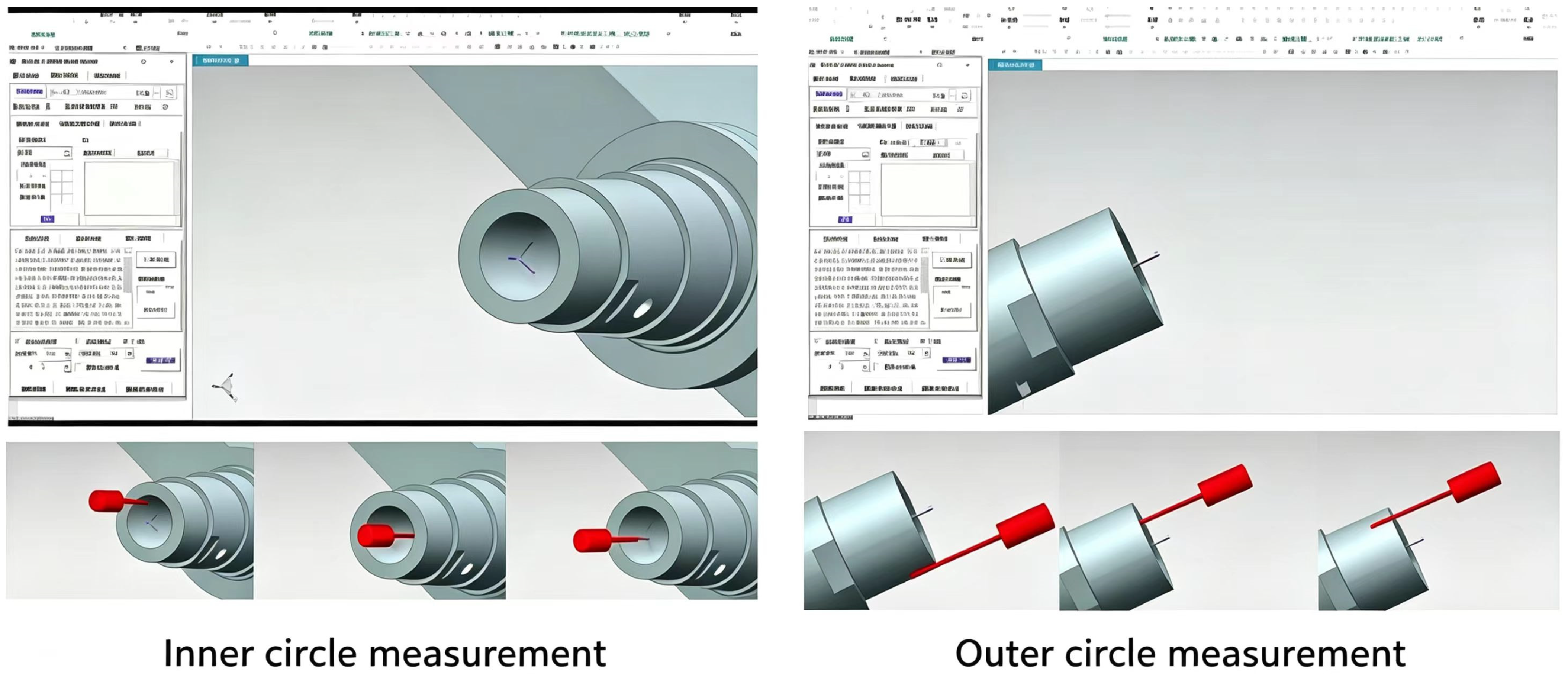
To realize collision-free and high-speed precision measurement for the inner and outer circular features of shaft-like components, standardized trajectory optimization and path planning rules are formulated, as intuitively illustrated in Figure 1. The path planning strategy adheres to dual principles of operational safety and detection efficiency, and is divided into three continuous stages: approaching, stable measurement, and probe retracting. As displayed in the subgraphs of Figure 1, the measurement scenarios are classified into inner-hole and outer-circle detection, where the red probe trajectory demonstrates the complete three-stage motion cycle of the detection process. During path programming, all fixture structures are strictly avoided to eliminate collision risks, and a continuous surface contact sampling sequence is adopted [16]. The upper software simulation window in Figure 1 presents the pre-optimized measurement trajectory, which maintains a safe clearance from surrounding fixtures and achieves uninterrupted uniform sampling on cylindrical surfaces. For batch multi-point measurement tasks, the nearest neighbor algorithm is employed to optimize the sampling sequence, and safety isolation planes are configured between adjacent sampling points. The progressive probe pose diagrams further verify the shortest-distance transfer logic of the nearest neighbor algorithm. The arranged safety planes serve as effective isolation barriers during high-speed position switching, significantly enhancing the operational safety and stability of the high-speed measurement process. Overall, Figure 1 systematically demonstrates the integrated technical scheme of path planning, simulation verification and collision avoidance for inner-hole and outer-cylinder on-machine inspection of shaft workpieces [17].

2.2.4. Hardware Composition of Trigger-Based On-Machine Detection System

The core hardware configuration of the developed trigger-based on-machine detection system mainly comprises high-precision trigger probes (including Renishaw and BLUM series), dedicated signal receivers and matched signal transmission interfaces. The selection of probe models is determined by multiple practical factors, including the types of CNC machine tool spindles (milling and turning spindles), effective measurement range, environmental protection grade (coolant and scrap metal resistance), and key precision indicators, with the measurement repeatability strictly constrained within 1 μm. The signal receiver is configured to match the numerical control system brand, and is equipped with standard probe holders and extension rods to accommodate the installation and measurement demands of various workpiece features [18]. During system integration, signal anti-interference optimization and electrical isolation design are regarded as the primary design priorities, aiming to ensure long-term operational stability and measurement reliability of the detection system under complex actual machining workshop conditions [19].
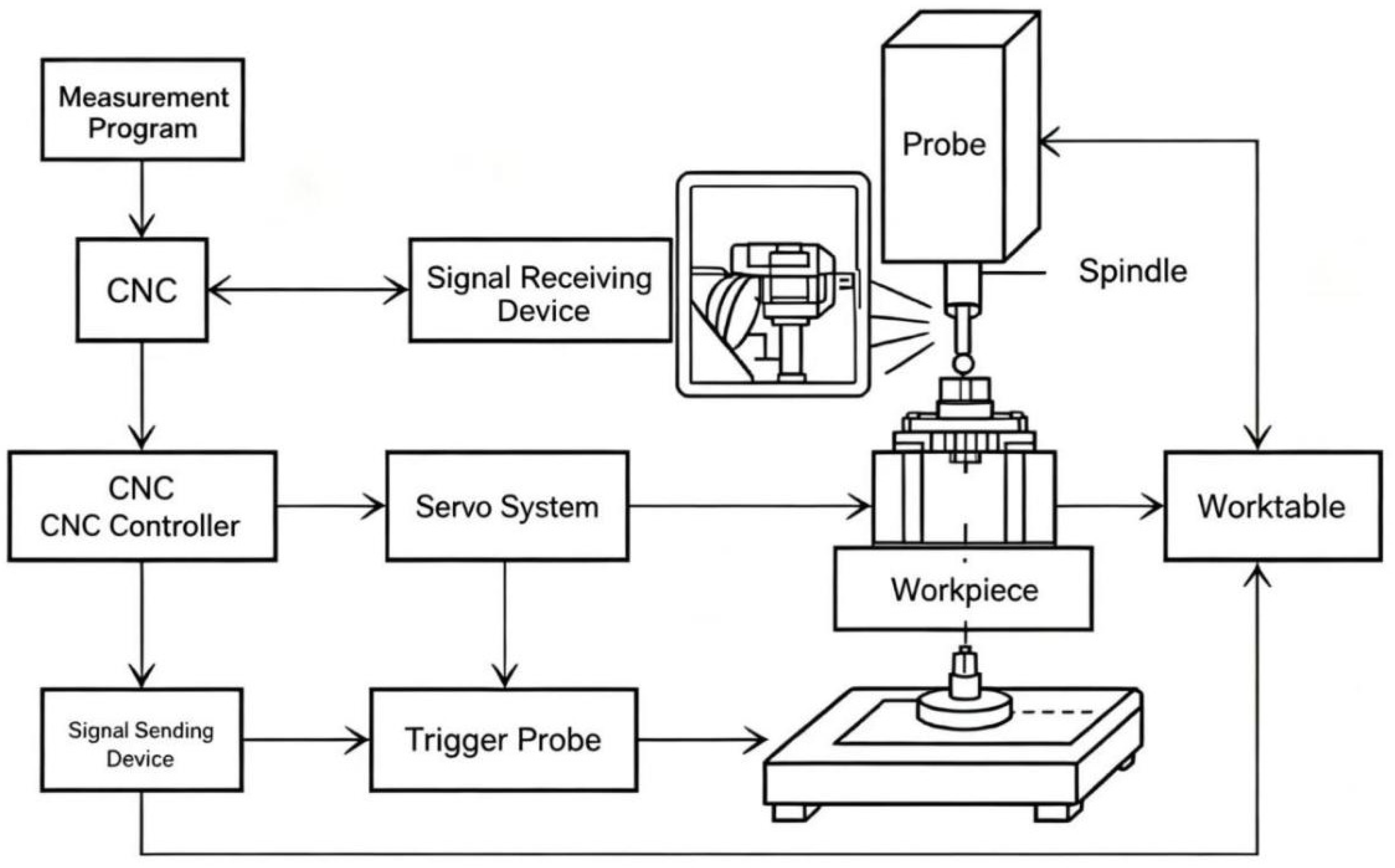
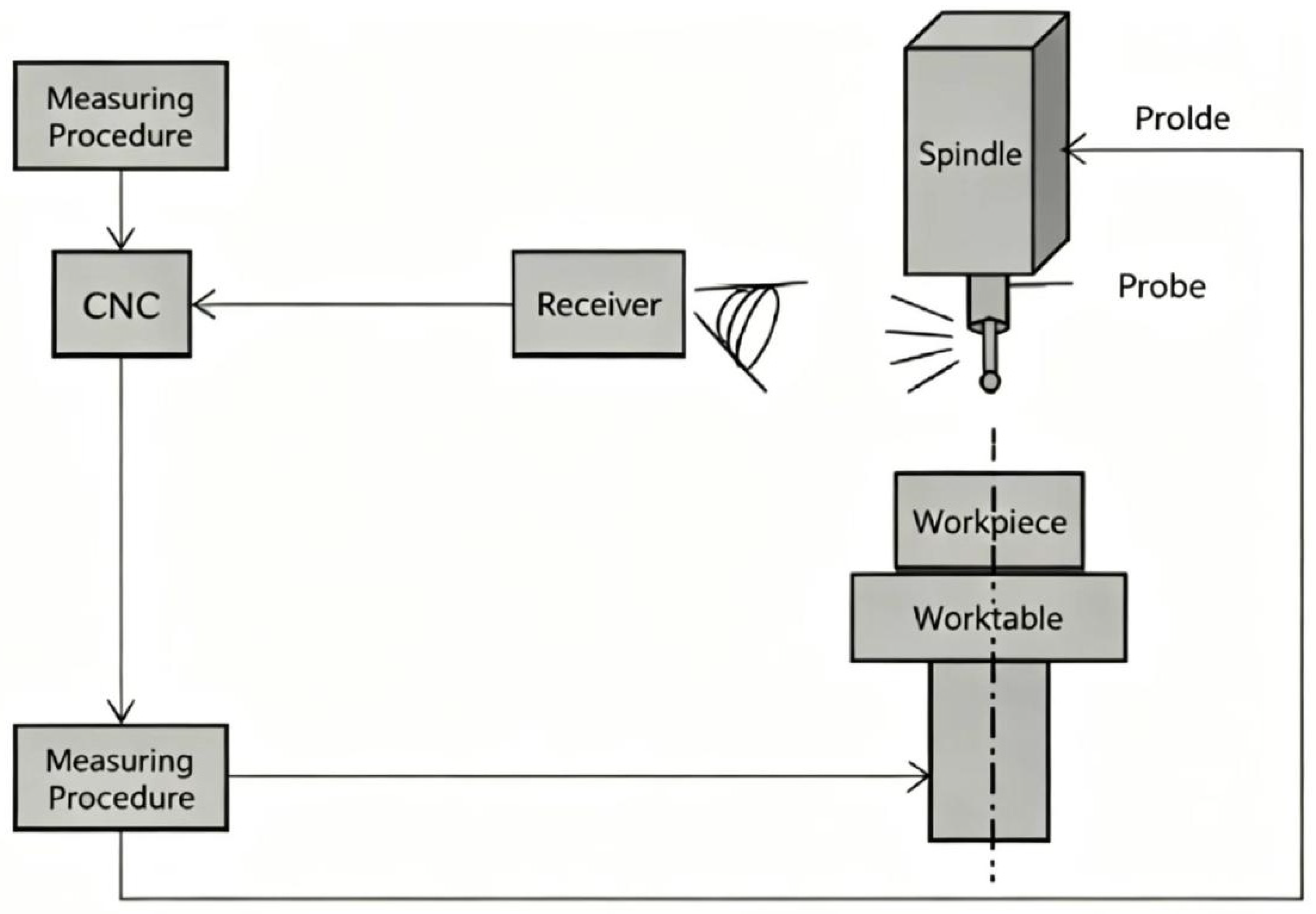
Figure 2 presents the schematic working principle of the proposed CNC on-machine measurement system. The overall system is composed of multiple independent functional modules, including measurement programming unit, numerical control system, machine tool spindle, trigger probe, signal transceiving device and tested workpiece, all of which are modularized and visualized in the block diagram. The specific operating workflow is described as follows. The precompiled measurement program delivers motion commands to the CNC module, which further transmits control signals to the CNC controller and servo system. Driven by the servo system, the machine tool spindle equipped with the trigger probe and the workpiece-loaded worktable execute coordinated feeding motion. Meanwhile, the CNC controller is interconnected with the signal transmitting device integrated with the trigger probe. Once effective contact is formed between the probe tip and the workpiece surface, a trigger signal is generated and transmitted back to the signal receiving device. The fed-back signal subsequently triggers the CNC system to terminate the feeding motion and synchronously record the real-time coordinate data.
The closed-loop signal transmission and mechanical execution framework shown in the block diagram clearly reveals the cooperative matching mechanism among the trigger probe, signal transceiving unit and CNC hardware platform. The independent signal transmission channel in the diagram validates the anti-interference and electrical isolation design adopted during system integration, which guarantees stable and reliable signal interaction under complex machining interference environments.
In practical detection, the measurement program outputs optimized path instructions to the numerical control system, which drives the servo system and spindle to actuate the trigger probe and worktable for collaborative measurement motion. Surface contact between the probe and workpiece activates the wired or wireless signal transmission module at the probe end, and the generated trigger signal is fed back to the CNC system. The system precisely captures the machine coordinates at the triggering moment, completes the on-machine acquisition of workpiece dimensional and form-position errors, and constructs a complete position feedback closed loop to achieve high-precision measurement control.
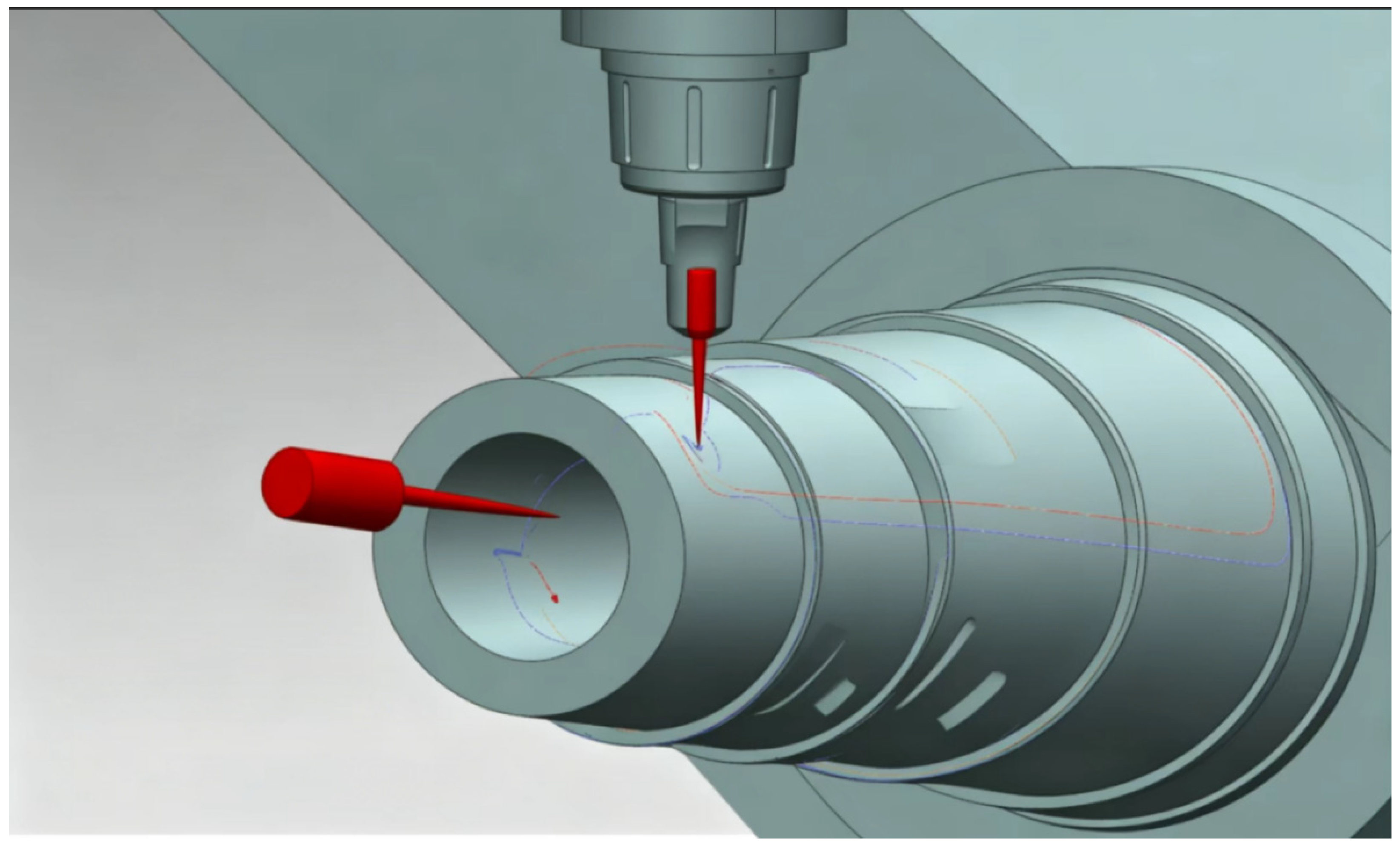
Figure 3 demonstrates the three-dimensional simulation of measurement path planning, operational process and collision avoidance strategy. As visualized in the 3D rendering, dual trigger probes are deployed to implement synchronous sampling for the inner hole and outer cylindrical surfaces of shaft workpieces, where the colored curved trajectories distributed on the workpiece surface represent the pre-programmed measurement paths generated by the measurement system. The spatial layout of the dual probes fully reflects the coordinated motion logic of the spindle-mounted probe and workpiece-carrying worktable driven by the servo system. The reserved safe clearance between the probe bodies and workpiece edges realizes the embedded collision avoidance function of the path planning strategy. Additionally, the close contact sampling state between the probes and circular workpiece surfaces conforms to the trigger signal generation mechanism of contact on-machine detection. The 3D simulation results intuitively visualize the entire closed-loop measurement control workflow, which further verifies the reliability and feasibility of the proposed high-precision on-machine detection mechanism.
However, even after completing the on-machine measurement workflow, the efficiency of measurement path planning and the difficulty of searching for the global optimum remain critical bottlenecks limiting overall detection performance. Accordingly, Section 3 proposes a novel PSO–SA hybrid optimization algorithm and embeds it into the intelligent optimization module for inspection trajectory generation, so as to further elevate the comprehensive operational efficiency of the integrated detection system.

3. PSO–SA Hybrid Optimization Algorithm for Flatness Fitting and Inspection Path Planning

To implement efficient, intelligent flatness inspection trajectory planning for irregular curved components and simultaneously boost measurement precision and detection efficiency, a series of intelligent optimization approaches have been widely adopted, including simulated annealing (SA), particle swarm optimization (PSO) [20], and serial PSO–SA hybrid frameworks, for system optimization and measurement path generation. Nevertheless, conventional serial PSO–SA architectures only adopt unidirectional single-stage information delivery: they merely transmit the optimal solutions obtained from PSO to SA without closed-loop feedback correction. Such frameworks lack targeted theoretical design tailored to the non-convex multi-extremum minimum zone flatness fitting problem of free-form aircraft rudder surfaces [21]. This subsection elaborates the theoretical innovations, dedicated matching mechanism, mathematical optimization model, constraint criteria and complete iterative workflow of the proposed bidirectionally closed-loop coupled PSO–SA hybrid algorithm. Furthermore, it systematically distinguishes the fundamental differences between the proposed method and single intelligent algorithms, traditional serial PSO–SA schemes, and classical flatness evaluation approaches from a theoretical perspective [22].

3.1. Fundamentals of PSO and SA Optimization Algorithms

Particle swarm optimization (PSO) achieves optimal solution searching by mimicking the collective social foraging behavior of bird flocks. Each particle stands for a candidate solution within the search space. During iterative evolution, every particle updates its velocity and position by tracking its personal historical optimum and the global swarm optimum, thereby completing collaborative global search across the solution domain. PSO features an intuitive operating principle, few hyperparameters, fast initial convergence and straightforward implementation. Its dominant limitation lies in premature convergence and high susceptibility to local optima, which restricts the solution precision when tackling complex multi-peaked optimization problems [23]. The standard execution procedures of PSO are summarized as follows: first, initialize the position and velocity of all swarm particles; second, calculate the fitness value of each particle; third, update individual personal best and swarm global best according to fitness evaluation results; fourth, adjust particle velocities and positions via predefined update formulas; finally, repeat the fitness evaluation and parameter update loop until the maximum iteration threshold or preset precision criterion is satisfied [24].
Simulated annealing (SA) draws inspiration from the physical annealing process of solid materials. It leverages a temperature-dependent probability criterion to accept inferior candidate solutions, enabling the algorithm to escape local optimal regions [25]. SA exhibits strong universality and robust capacity for solving highly nonlinear optimization problems, yet it suffers from slow convergence speed and heavy reliance on empirical parameter tuning. The standard SA workflow is outlined below: initialize the annealing temperature and an original candidate solution; generate neighboring candidate solutions in each iteration and accept suboptimal solutions following the Metropolis probability rule; gradually cool down the temperature parameter and repeat the neighborhood search cycle until the termination condition is triggered [26].

3.1.1. Theoretical Deficiencies of Existing Optimization Algorithms and Classical Flatness Fitting Methods

To highlight the theoretical novelty of the proposed bidirectionally coupled PSO–SA algorithm, this subsection systematically analyzes the inherent theoretical defects of mainstream comparison algorithms when applied to flatness evaluation of aircraft rudder surfaces [27]. The root causes accounting for the failure of conventional methods to realize high-precision flatness fitting on noisy free-form surfaces with non-uniform point cloud distribution are clarified as follows.
For standard PSO and its improved variants, fixed or linearly varying inertia weights are universally deployed. Such weight adjustment schemes fail to accommodate drastic residual fluctuations arising from curvature-adaptive sampling on free-form rudder surfaces, which makes the algorithms converge prematurely to local optimal planes dominated by locally dense measurement points. Moreover, existing modified PSO strategies only revise single-particle update rules without integrating the annealing probabilistic jump mechanism to suppress disturbances induced by on-machine trigger sampling noise.
Standard SA and its improved derivatives possess no group parallel searching mechanism, leading to extremely low iterative efficiency when processing over 80 measurement points in aeronautical engineering applications. In addition, single SA algorithms merely rely on neighborhood perturbation of an isolated solution, lacking the rapid rough localization capability required to narrow down the feasible solution space of plane fitting parameters [28].
Genetic algorithm (GA) and ant colony optimization (ACO) involve cumbersome crossover, mutation and pheromone iteration rules. When addressing the low-dimensional optimization problem of plane equation coefficients, both algorithms exhibit slow convergence. Neither GA nor ACO embeds a noise threshold correction module to eliminate measurement errors introduced by CNC trigger probes.
Linear programming and traditional minimum zone evaluation methods are only applicable to regularly distributed sampling points without noise interference [29]. These approaches cannot mitigate fitting deviations caused by nonlinear trigger probe measurement noise, and their convex solving frameworks become invalid for the non-convex multi-extremum residual objective function constructed for curved free-form rudder surfaces.
In addition, conventional serial PSO–SA hybrid algorithms follow unidirectional open-loop iteration logic [30]. Specifically, the global optimum solved by PSO is directly imported into SA for local refinement, while the refined solutions generated by SA cannot be fed back to refresh particle swarm population information. In these general hybrid architectures, inertia weights still adopt fixed or linear variation modes, and the standard Metropolis acceptance criterion excludes correction terms dedicated to measurement noise. Therefore, existing serial PSO–SA frameworks act as universal general hybrid structures without targeted theoretical optimization for minimum zone flatness evaluation tasks.

3.1.2. Dedicated Bidirectionally Coupled PSO–SA Algorithm for Rudder Surface Flatness Evaluation

Distinct from conventional serial PSO–SA hybrids, modified PSO, modified SA, GA, ACO, linear programming and classical minimum zone evaluation methods [31], this work proposes a customized PSO–SA hybrid optimization algorithm specially tailored for flatness error evaluation of aircraft curved rudder surfaces. A closed-loop bidirectionally coupled iterative framework is constructed to tackle the non-convex minimum zone flatness fitting problem of free-form rudder components. The theoretical adaptability of the proposed algorithm for flatness assessment is analyzed, and three core theoretical innovations that distinguish this method from existing research are summarized as follows:
  • Innovation 1: Bidirectional Closed-Loop Information Interaction Iterative Framework
Unlike the unidirectional serial iteration architecture adopted by traditional PSO–SA hybrids, the proposed algorithm establishes a bidirectional closed-loop information transmission channel. After SA executes probabilistic perturbation refinement on the optimal plane parameters output by PSO, the noise-suppressed refined solution is reversely fed back to update the swarm global optimum for the subsequent PSO iteration. This two-way interaction mechanism enables mutual calibration between swarm-driven global exploration and single-solution annealing local jumps, effectively eliminating the information loss defect inherent to open-loop serial hybrid strategies.
  • Innovation 2: Residual-Adaptive Nonlinear Dynamic Inertia Weight Strategy
All existing PSO–SA hybrid models adopt linear inertia weight adjustment, whereas this study constructs a residual-coupled nonlinear inertia weight function. The function dynamically balances global exploration and local exploitation according to the fluctuation characteristics of fitting residuals from rudder surface sampling points. In the early iteration stage, the inertia weight adaptively rises to expand the search space and realize fast rough positioning of candidate optimal fitting planes. A moderate constant inertia weight is maintained in the middle iteration phase to sustain stable global swarm searching. In the late iteration stage, the inertia weight gradually declines to shrink the search range and facilitate high-precision local optimization. This nonlinear tuning scheme matches the residual mutation characteristics of non-uniform sampling points on free-form surfaces, which cannot be realized via conventional linear inertia weight strategies.
  • Innovation 3: Measurement Noise-Modified Metropolis Probability Acceptance Criterion
A noise threshold correction term is embedded into the classical SA Metropolis acceptance criterion, forming an annealing judgment rule dedicated to flatness evaluation. The improved criterion adaptively adjusts the acceptance probability of inferior solutions based on the magnitude of trigger probe measurement noise collected from rudder surface sampling. When the deviation of a newly generated plane solution originates from random sampling noise, the algorithm moderately increases the probability of accepting suboptimal candidates, so as to avoid convergence to local optimal planes formed by noise-contaminated dense sampling points. This noise-sensitive temperature attenuation rule constitutes a task-oriented theoretical improvement absent from universal standalone SA algorithms and traditional serial PSO–SA hybrid frameworks.
Essentially, rudder surface flatness error calculation is a non-convex minimization problem governed by a multi-extremum residual objective function. The fast group search capacity of PSO satisfies the demand for rapid rough localization of candidate ideal planes in early iterations, while the probabilistic inferior-solution acceptance mechanism of SA allows the algorithm to escape local optimal planes induced by partial dense measurement points—a unique theoretical advantage unavailable to standalone PSO, linear programming and classical minimum zone methods. Meanwhile, the bidirectional information interaction between the PSO particle swarm and SA annealing process overcomes the major drawback of conventional serial PSO–SA schemes, which only transmit PSO outputs to SA without reverse feedback optimization.
The proposed hybrid algorithm first leverages the swarm collaboration mechanism of PSO, together with the residual-adaptive nonlinear dynamic inertia weight strategy (differentiated from linear inertia weights used in all prior PSO–SA frameworks), to balance global exploration and local exploitation and rapidly converge to the rough optimal region of plane fitting parameters. On this basis, the measurement noise-modified Metropolis acceptance criterion of SA is introduced to accept suboptimal plane coefficient solutions under controllable cooling temperature, effectively preventing stagnation at local optima triggered by uneven rudder sampling distribution and random measurement noise. This task-customized hybrid architecture retains the fast convergence merit of PSO and strengthens the global optimization capability and anti-noise robustness of plane fitting via temperature-controlled random perturbation of noise-corrected SA.
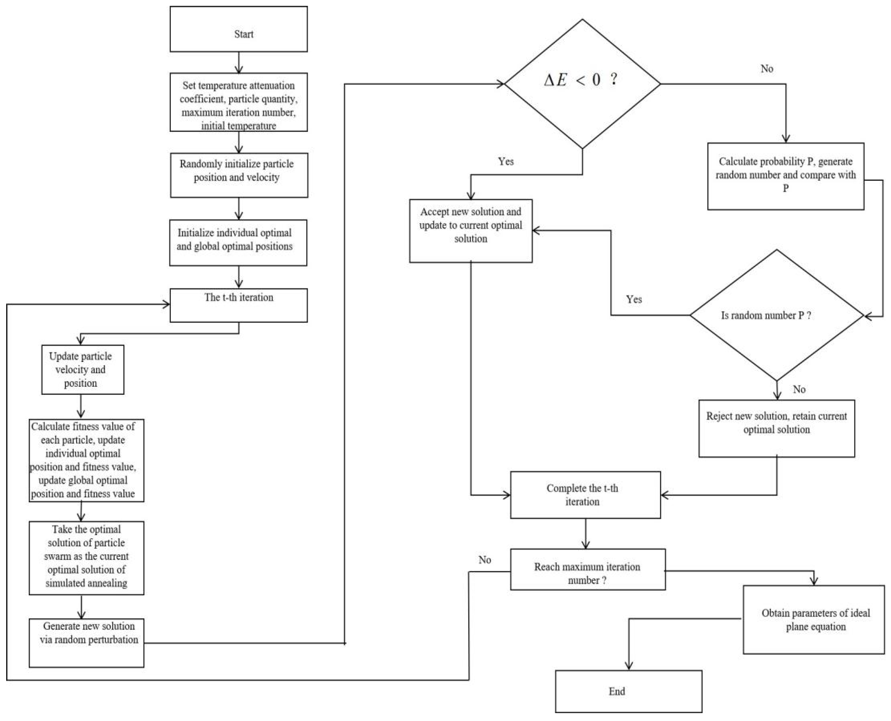
The entire searching process relies on residual-linked adaptive inertia weight tuning and a measurement-noise-sensitive temperature decay mechanism to achieve progressive coarse-to-fine two-layer optimization exclusively designed for flatness error evaluation. Ultimately, the algorithm solves a high-precision ideal plane equation complying with the minimum enclosing zone criterion, which outperforms universal hybrid algorithms when applied to multi-extremum flatness optimization scenarios with noisy free-form surface point clouds. The complete iterative flowchart for solving ideal plane equation parameters via the proposed bidirectionally coupled PSO–SA hybrid optimization algorithm is presented in Figure 4.
As illustrated by the complete iterative logic in Figure 4, the left branch fully implements the PSO module embedded with the residual-adaptive nonlinear inertia weight strategy. The overall workflow initiates with the configuration of core hyperparameters, including initial annealing temperature, inertia weight, and particle swarm scale. Subsequent procedures involve particle position initialization, velocity and position iterative updating, adaptive residual-based fitness evaluation, individual personal best (pbest) and global best (gbest) optimization, and stochastic mutation operations, which faithfully realize the swarm collaboration and global-local search balancing mechanism proposed in this study. The right branch of the flowchart corresponds to the improved SA module integrated with the measurement noise-modified Metropolis acceptance criterion. The judgment logic of ΔE < 0 and stochastic probability comparison reproduces the temperature-dependent inferior solution acceptance strategy, enabling the algorithm to escape local optima caused by non-uniform point cloud distribution and on-machine sampling noise. The bidirectional data interaction between the PSO iterative loop and SA annealing judgment branch intuitively demonstrates the closed-loop information transmission characteristic of the proposed hybrid framework, which fundamentally breaks the unidirectional open-loop output limitation of conventional serial PSO-SA architectures. The entire iterative process adheres to a progressive coarse-to-fine two-stage optimization logic. The PSO swarm search achieves rapid rough positioning of plane fitting parameters, while the SA annealing perturbation performs high-precision refinement within the optimal solution region. Once the predefined iteration threshold is satisfied, the near-optimal plane parameter solution for flatness evaluation is outputted. This complete workflow fully validates the progressive double-layer optimization design and verifies the superior robustness of the proposed algorithm in solving multi-extremum flatness error optimization problems for complex curved surfaces.

3.2. Optimization Objectives

The core optimization target of the proposed hybrid algorithm is to solve the optimal ideal plane equation via the synergistic combination of PSO and SA strategies, where the plane equation coefficients are defined as the decision variables for iterative optimization. Distinct from conventional general optimization problems [32], the objective function is specially constructed to comply with the geometric tolerance-based minimum zone flatness evaluation criterion for aeronautical components. Instead of simply minimizing the mean square error, the proposed optimization strategy takes the extremum of distance deviations between free-form rudder surface sampling points and the candidate fitting plane as the optimization target. The algorithm minimizes the distance-based fitness function (i.e., the objective function), which quantitatively evaluates plane fitting quality by calculating the vertical distance from each on-machine sampling point to the candidate plane. The optimized ideal plane is finally adopted to calculate the flatness error, which is defined as the difference between the maximum and minimum point-to-plane distances within the minimum enclosure zone [33].

3.3. Constraint Conditions

The operational constraints of the bidirectionally coupled PSO-SA algorithm are formulated and calibrated targeting the geometric characteristics and actual on-machine measurement noise environment of aircraft rudder surfaces, which are specified as follows:
(1) Iteration control constraints. The PSO module is constrained by the maximum iteration number and swarm population size. The SA module is configured with initial temperature and temperature decay coefficient, and implements probabilistic inferior solution acceptance. All iterative hyperparameters are finely calibrated according to the actual measurement scale and noise amplitude of aircraft rudder surfaces, forming dedicated parameter constraint criteria adapted to aviation flatness detection scenarios.
(2) Iteration update and acceptance criteria. Particle velocity and position are updated following standard PSO iterative formulas. Individual and global optimal solutions are dynamically updated based on real-time fitness comparison. For the SA iteration process, inferior candidate solutions are accepted with adaptive probabilities governed by the proposed noise-modified Metropolis criterion, which enhances the algorithm’s anti-interference capability against field sampling noise.
(3) Termination constraints. The iterative loop terminates when the maximum iteration number is reached, and the current optimal solution is output as the final ideal plane parameter. The termination threshold is reasonably set according to the micron-level precision requirements of aviation component flatness detection, which effectively avoids the insufficient convergence and redundant over-iteration problems existing in conventional general hybrid algorithms.

3.4. Algorithm Steps and Flow

  • Step 1: Construct the objective function by calculating the distances from measuring points to the ideal plane
The perpendicular distance from each measuring point to the ideal plane is solved based on the general plane equation. The signed distance from the i-th measuring point to the ideal plane is expressed as:
d i = A x i + B y i + C z i + D A 2 + B 2 + C 2       ( i = 1 , 2 , , n )
where d i denotes the signed perpendicular distance from the i -th measuring point to the ideal plane; ( x i , y i , z i ) represents the 3D coordinate of the i -th measuring point; A , B , C and D are undetermined coefficients of the ideal plane equation; n is the total number of measuring points distributed on the rudder surface. In accordance with the minimum zone criterion for flatness evaluation, the flatness error is defined as the minimum separation distance between a pair of parallel planes enclosing all measuring points, which equals the difference between the maximum and minimum signed distances from all measuring points to the fitted plane. Therefore, the flatness evaluation problem is transformed into minimizing the gap between d max and d min , and the corresponding objective function is established as:
min f ( A , B , C , D ) = min max 1 i n d i min 1 i n d i
Subject to A 2 + B 2 + C 2 0 to avoid invalid zero normal vectors.
  • Step 2: Solve the objective function via hybrid PSO-SA algorithm to obtain the optimal ideal plane parameters
2.1 Parameter initialization Set the population size and maximum iteration number of the particle swarm optimization (PSO) algorithm, as well as the initial temperature and temperature attenuation coefficient of the simulated annealing (SA) algorithm. Randomly initialize the position and velocity of all particles, along with the personal best position pbest and global best position gbest. The position vector of each particle corresponds to a set of plane coefficients (A, B, C, D).
2.2 Update particle velocity and position in the k-th iteration. The velocity and position of each particle are updated by the following formulas:
v j , t + 1 = ω t v j , t + c 1 r 1 ( pbest j x j , t ) + c 2 r 2 ( gbest j x j , t )
x j , k + 1 = x j , k + v j , k + 1
where j is the particle index; v j , k and v j , k + 1 represent the velocity of the j-th particle at the k-th and ( k + 1 ) -th iterations, respectively; v j , k and v j , k + 1 denote the position of the j-th particle at the k-th and (k + 1)-th iterations, respectively; p best , j is the historical personal optimal position of the j-th particle; g best , k is the global optimal position in the k-th iteration; ω k stands for the dynamic inertia weight at iteration k; c 1 and c 2 are acceleration factors; r 1 and r 2 are uniformly distributed random numbers ranging from 0 to 1.
A piecewise dynamic inertia weight strategy is adopted to balance global exploration and local exploitation:
ω k = ω min + ( ω max ω min ) g ( k ) k k 1 ω mid k 1 < k k 2 ω max ( ω max ω min ) g ( k ) k > k 2
g ( k ) = k G max  
where g ( k ) is the normalized iteration coefficient for balancing global and local search capabilities (see Figure 2); ω max and ω min are the upper and lower bounds of inertia weight; ω mid is the constant inertia weight in the middle iteration stage; k 1 , k 2 and G max are preset constant thresholds and the maximum iteration count, respectively.
A larger inertia weight expands the particle search range and strengthens global search capacity while weakening local search precision; conversely, a smaller inertia weight narrows the search domain and improves local exploitation but weakens global exploration. According to Equations (5) and (6), increases with iterations in the early stage, expanding the search space to accelerate global convergence and rapidly capture promising candidate solutions. During the middle iterations, ω k remains constant to stabilize the searching process and prevent solution collapse. In the late iteration stage, ω k gradually decreases to shrink the search range, facilitating precise local search for high-accuracy optimal solutions.
For each particle, the signed distances of all sampled measuring points on the rudder surface are calculated via Equation (1), and the fitness value corresponding to the particle’s current position is obtained by substituting distances into the objective function Equation (2). The current fitness value is compared with the historical personal optimal fitness of the particle: if the current fitness is smaller, update p b est , j to the current particle position and refresh the personal optimal fitness value; otherwise, retain the original personal best position and fitness. After evaluating all particles in the k-th iteration, the minimum personal optimal fitness is selected as the global optimal fitness of this iteration, and the corresponding particle position is assigned to g b est , k as the current optimal solution of PSO.
2.3 Metropolis criterion of simulated annealing
Take the global optimal solution g b est , k obtained from the k-th PSO iteration as the current optimal solution X cur of the SA module. A new candidate solution X new is generated by random neighborhood perturbation on X new . Compute the signed distances of measuring points for both solutions via Equation (1) and calculate their corresponding fitness values. The fitness difference between the new and current solution is defined as:
Δ f = f ( X new ) f ( X cur )
The acceptance probability of the candidate solution is formulated as:
P ( Δ f , T k ) = 1 Δ f < 0 exp Δ f T k Δ f 0
where Δ f is the fitness difference; T k represents the annealing temperature at the k-th iteration; the temperature update rule is T k + 1 = λ T k , with T 0 denoting the initial temperature and λ the temperature attenuation coefficient. If Δ f < 0 , the new candidate solution yields a smaller flatness error and is directly accepted to replace X cur . If Δ f 0 , the new solution is inferior to the current one. Generate a random number ξ [ 0 , 1 ] and compare it with probability P ( Δ f , T k ) : the inferior new solution is accepted if ξ < P ( Δ f , T k ) to escape local optima; otherwise, the original current optimal solution is preserved. After temperature attenuation, one complete hybrid iteration is finished.
2.4 Termination judgment
Judge whether the current iteration number k reaches the preset maximum iteration G max . If the termination condition is satisfied, output the current optimal plane coefficients; otherwise, set k = k + 1 .
and repeat Steps 2.2–2.3 for the next iteration until the maximum iteration limit is reached. The optimal plane coefficients derived from the final iteration are used to construct the ideal plane equation.
  • Step 3: Calculation of final flatness error
Randomly sample multiple measuring points from the rudder surface, calculate their signed distances to the solved optimal ideal plane via Equation (1). The flatness error equals the difference between the maximum and minimum signed distances of all measuring points.

4. Plane Flatness Detection Path Simulation Analysis

4.1. Simulation Environment and Parameter Settings

To validate the effectiveness and performance superiority of the proposed residual-adaptive bidirectionally coupled PSO-SA hybrid optimization algorithm in the flatness evaluation of aircraft control surfaces, comparative simulation experiments are implemented based on the MATLAB R2022a (Windows 64-bit) platform. All algorithm programs are independently coded without relying on third-party toolboxes, ensuring full experimental reproducibility. To guarantee a fair and rigorous comparative benchmark, all simulation groups adopt identical hardware conditions, measurement point datasets, iterative termination criteria and constraint parameter configurations [34].
The measurement point datasets are constructed in accordance with the practical manufacturing and assembly error characteristics of aircraft rudder surfaces. Specifically, the control surface is approximated as an ideal reference plane, where a certain number of sampling points are uniformly distributed on the planar domain [35]. Normal-distributed random offset disturbances are superimposed on these sampling coordinates to simulate actual machining and assembly errors that conform to aeronautical engineering statistical characteristics. The minimum zone criterion is employed as the flatness evaluation benchmark in all simulation tests, in which the flatness error is defined as the difference between the maximum and minimum point-to-plane distances of all sampling points relative to the optimized fitting plane [36].

Comparison Algorithm Selection

To comprehensively verify the performance advantages of the proposed algorithm over mainstream metaheuristic methods in flatness error evaluation, six representative optimization algorithms are selected for comparative simulation, covering basic single metaheuristic algorithms, improved single optimization variants, and conventional PSO-SA hybrid benchmark models. The parameter configurations and core characteristics of each comparative algorithm are specified as follows. The standard particle swarm optimization (PSO) is configured with a swarm size of 30 particles and a maximum iteration number of 100, adopting a conventional linear dynamic inertia weight strategy. The standard simulated annealing (SA) is initialized with a starting temperature of 100 and a temperature decay coefficient of 0.95, and utilizes the classical Metropolis criterion for inferior solution acceptance. As a widely adopted improved PSO variant for form error evaluation, comprehensive learning particle swarm optimization (CLPSO) integrates historical optimal information from all particles to maintain population diversity and suppress premature convergence. The adaptive cooling SA is a state-of-the-art modified SA variant that adopts iteration-adaptive temperature decay scheduling to enhance local searching precision. The traditional serial fixed-coupling PSO-SA algorithm serves as the classic hybrid baseline model, which realizes simple modular switching between PSO and SA without adaptive residual optimization and closed-loop feedback correction.
In contrast, the proposed bidirectionally coupled PSO-SA algorithm incorporates a residual-adaptive nonlinear inertia weight strategy for PSO global exploration and measurement noise-modified iterative updating for SA local exploitation, achieving adaptive threshold switching to dynamically balance global searching capability and local optimization accuracy. Furthermore, each algorithm is executed for 30 independent repetitive runs to eliminate the random interference of stochastic experimental errors, and the hyperparameter variation range remains consistent across all comparative groups to ensure experimental validity and comparability.

4.2. Comparison of Iterative Convergence Characteristics

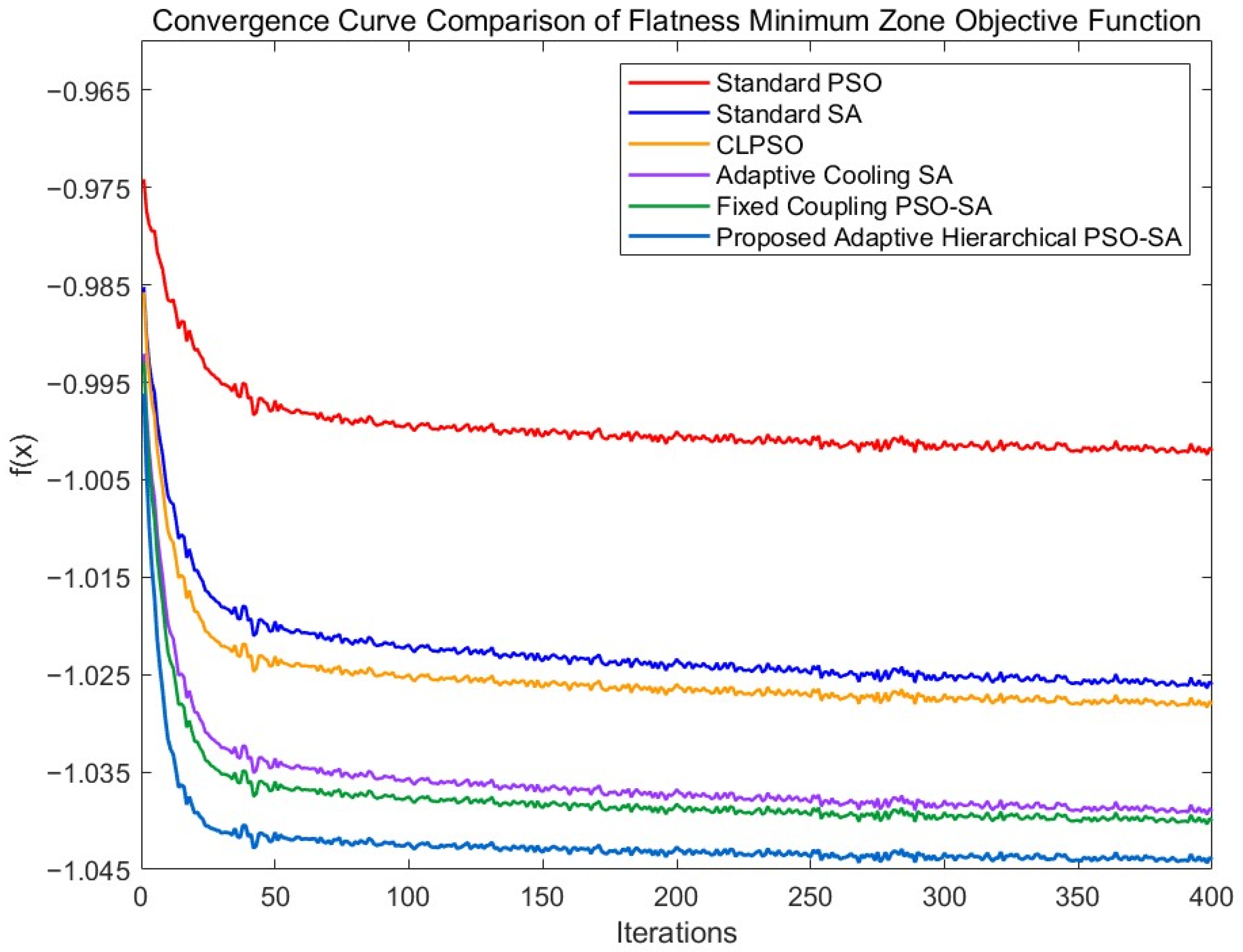
Figure 5 presents the objective function convergence curves of the minimum zone flatness evaluation model optimized by the six aforementioned algorithms. The horizontal axis represents the total iteration number ranging from 0 to 400, while the vertical axis denotes the objective function value corresponding to the minimum zone evaluation criterion. The comparative algorithms include standard PSO, standard SA, CLPSO, adaptive cooling SA, traditional fixed-coupling PSO-SA, and the proposed bidirectionally coupled PSO-SA algorithm, with distinct colored curves adopted to differentiate their iterative convergence trajectories.
A comprehensive quantitative analysis of algorithm performance is conducted from three core evaluation dimensions: convergence accuracy, convergence speed, and optimization stability.
First, the proposed algorithm achieves the highest convergence accuracy among all comparison methods. Throughout the entire iterative process, the proposed bidirectionally coupled PSO-SA algorithm maintains a consistently lower objective function value than all benchmark algorithms, converging stably to approximately −1.035 after 400 iterations. In comparison, the standard PSO only converges to −0.965, and the conventional fixed-coupling PSO-SA converges to approximately −0.985. The convergence accuracy of other improved single intelligent algorithms falls within the range between the above two values. This distinct performance discrepancy demonstrates that the proposed algorithm exhibits superior computational accuracy in solving the non-convex minimum zone flatness optimization problem for aircraft rudder surfaces.
Second, the proposed method delivers a faster convergence rate and stronger local optimum escape capability. Within the initial 100 iterations, the objective curve of the proposed algorithm declines significantly faster than those of all comparative methods, enabling rapid departure from local optimal regions and early convergence toward the global optimal solution. In contrast, standard PSO and standard SA present slow descent rates in the early iteration stage and are highly susceptible to premature convergence toward local extrema. Although CLPSO and adaptive cooling SA can mitigate premature convergence to a certain degree, their acceleration and optimization capabilities are considerably inferior to the bidirectional coupled optimization strategy proposed in this study.
Third, the proposed algorithm exhibits exceptional optimization stability in the late iteration stage. After 250 iterations, the convergence curves of all benchmark algorithms present obvious minor fluctuations and cease effective iterative updating, resulting in severe optimization stagnation. By comparison, the curve of the proposed bidirectionally coupled PSO-SA remains smooth and stable without conspicuous oscillations, which can reliably lock the global optimal solution and effectively eliminate the premature convergence and late-stage stagnation defects prevalent in conventional hybrid optimization algorithms.
In conclusion, compared with standard PSO, standard SA, improved single intelligent algorithms, and traditional fixed-coupling PSO-SA, the proposed bidirectionally coupled PSO-SA algorithm achieves comprehensive superiority in convergence speed, solution accuracy and optimization stability. The embedded adaptive switching mechanism between global exploration and local exploitation effectively resolves the inherent contradiction of conventional hybrid algorithms in balancing global searching ability and local refinement precision. The proposed method exhibits excellent engineering applicability for the minimum zone flatness evaluation of complex curved aircraft rudder surfaces.
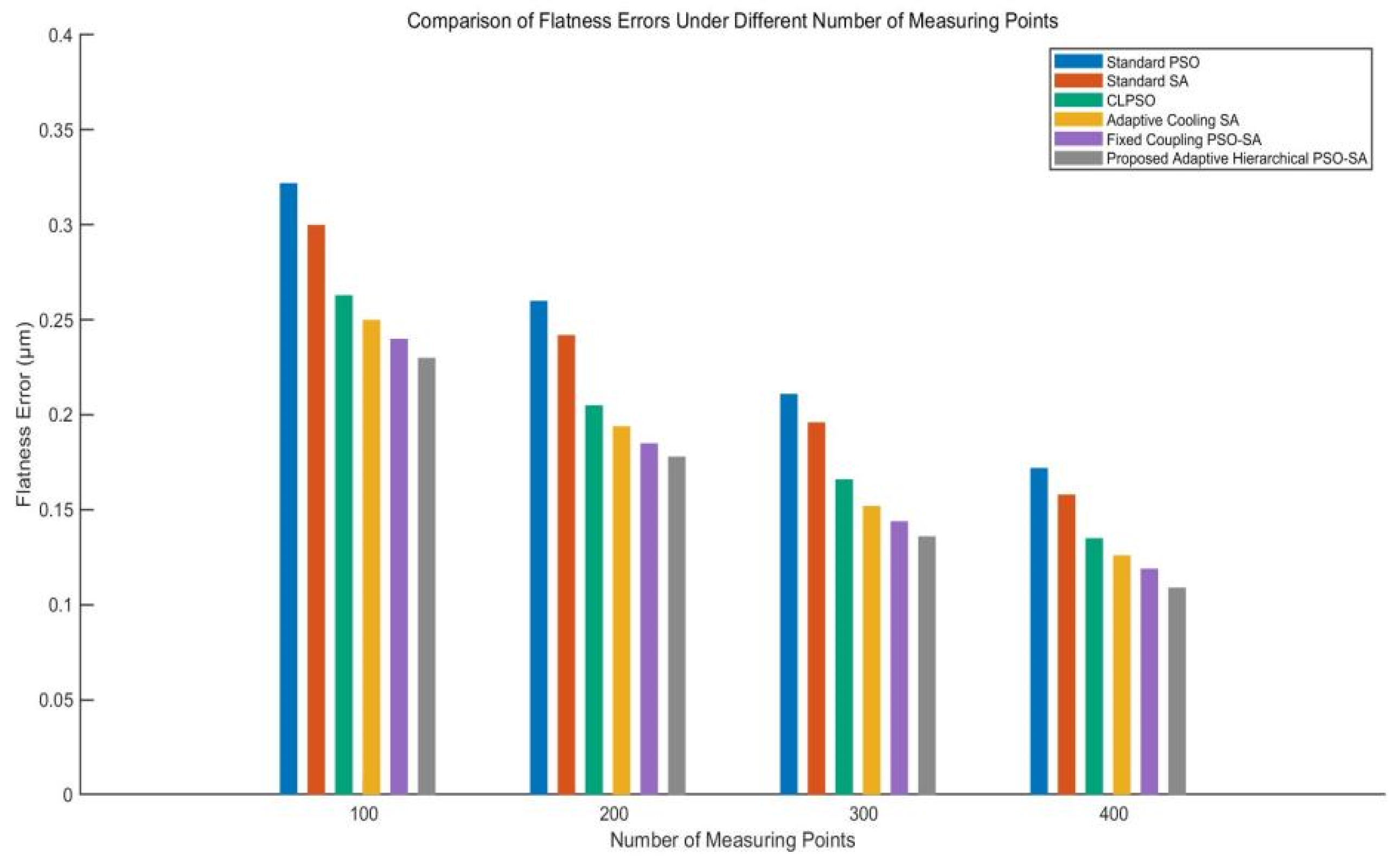
Figure 6 provides a quantitative visual comparison of flatness evaluation errors yielded by the six algorithms under four different sampling point densities (20, 40, 60, and 80 sampling points). The horizontal axis denotes the total number of sampling points deployed on the aircraft rudder surface, while the vertical axis represents the solved flatness error in micrometers (μm). All sampling points are uniformly distributed to fully cover the entire curved surface, and simulated machining deviation offsets are superimposed to reproduce the spatial distribution characteristics of actual on-machine measurement point clouds after practical manufacturing and assembly processes.
As observed from the experimental results, the flatness errors of all algorithms gradually decline with the increase in sampling point quantity. This trend indicates that denser sampling point distributions can comprehensively capture surface morphological features and effectively reduce flatness evaluation deviations. Nevertheless, under identical sampling conditions, the proposed bidirectionally coupled PSO-SA algorithm consistently yields the minimum flatness error among all comparative methods.
Standard PSO and standard SA produce the largest flatness errors across all sampling scenarios. The reference planes fitted by these two algorithms exhibit evident overall offset and fail to satisfy the minimum zone criterion, resulting in excessive distance deviations between partial sampling points and the fitted reference planes. Although CLPSO and adaptive cooling SA can reduce flatness errors to a certain degree, noticeable fitting deviations still occur at the edge sampling regions of rudder surfaces. In comparison, the reference plane solved by the proposed bidirectionally coupled PSO-SA can fully enclose all sampling points with the minimized difference between the maximum and minimum point-to-plane distances, which strictly conforms to the minimum zone flatness evaluation specification.
The flatness error comparison results illustrated in Figure 6 are highly consistent with the quantitative convergence performance analyzed in Figure 5, further validating that the proposed hybrid algorithm possesses superior fitting accuracy and reliable optimization performance for flatness evaluation of aircraft rudder surfaces.
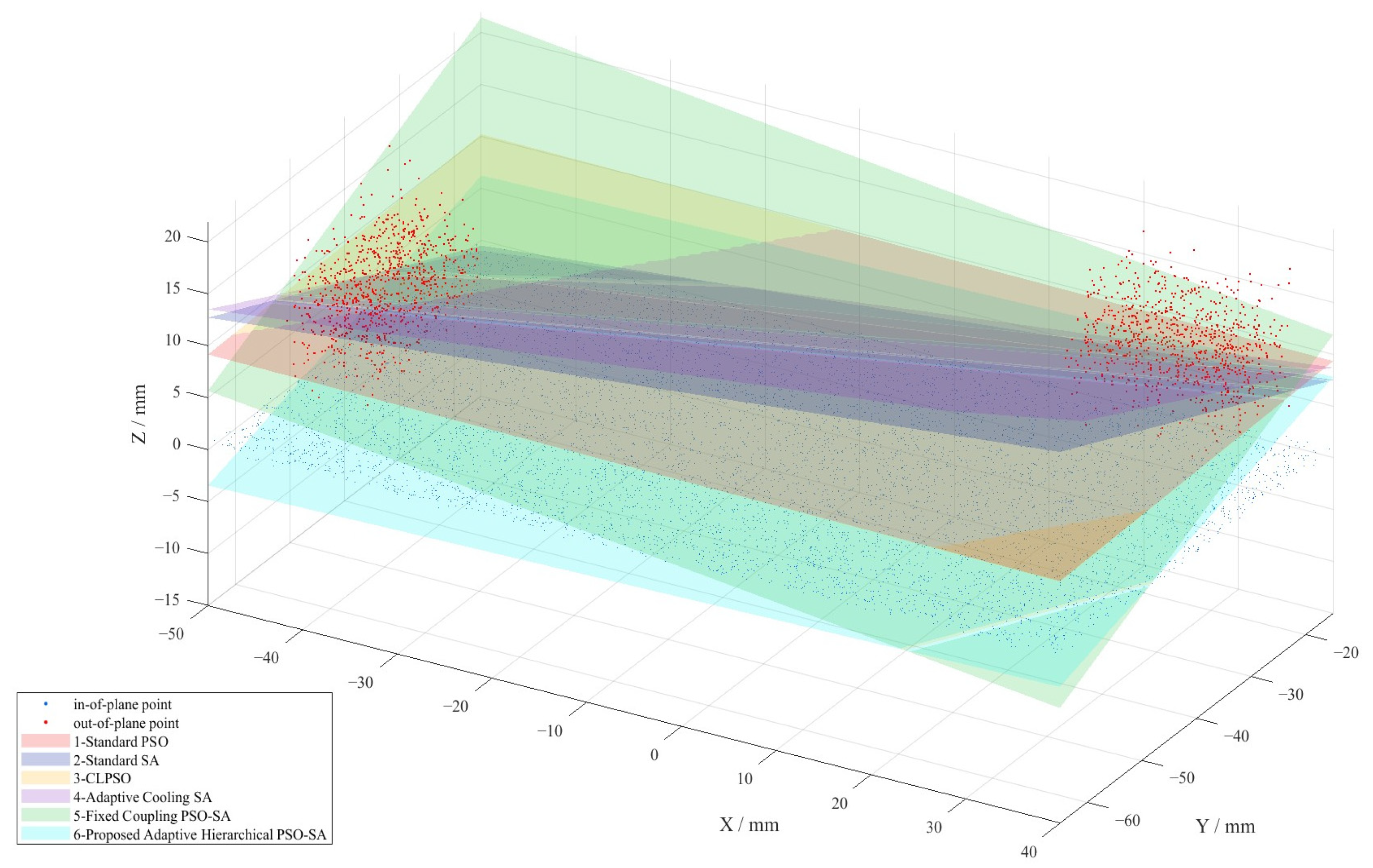
Figure 7 presents a three-dimensional visual comparison of the fitted reference planes obtained by the six algorithms and the corresponding sampling point distribution on aircraft rudder surfaces. The X, Y, and Z axes of the coordinate system are scaled in millimeters (mm). The blue scatter points represent ideal in-plane sampling points, while the red scatter points denote deviated points superimposed with simulated machining errors. Each translucent colored plane corresponds to the minimum zone reference plane fitted by standard PSO, standard SA, CLPSO, adaptive cooling SA, conventional fixed-coupling PSO-SA, and the proposed bidirectionally coupled PSO-SA, respectively.
The sampling points are uniformly arranged to cover the full profile of the rudder surface, and artificial machining offset errors are superimposed to replicate the spatial point distribution characteristics under actual manufacturing and assembly working conditions. Significant discrepancies in fitting and envelope performance are observed among different algorithms, which are summarized as follows:
(1) The reference planes fitted by standard PSO, standard SA, and conventional fixed-coupling PSO-SA suffer from severe overall offset. These planes fail to fully enclose all deviated sampling points, generating large vertical distances between marginal measurement points and the fitted planes and thus violating the fundamental minimum zone flatness evaluation criterion.
(2) CLPSO and adaptive cooling SA can moderately alleviate plane offset errors; however, prominent fitting deviations still exist for edge sampling points of the rudder surface, leading to a large interval between the upper and lower envelope planes and insufficient fitting compactness.
(3) In contrast, the reference plane derived from the proposed bidirectionally coupled PSO-SA algorithm completely envelopes all sampling points with the minimum point-to-plane distance fluctuation range. The fitted plane strictly complies with the minimum zone flatness evaluation specification and achieves the optimal overall fitting performance among all comparative algorithms.
The 3D visual fitting results are well consistent with the convergence curve quantitative analysis in Figure 5 and the flatness error statistical results in Figure 6. This multi-dimensional verification intuitively demonstrates the outstanding capability of the proposed algorithm in reference plane solving and high-precision minimum zone flatness fitting for aircraft curved rudder surfaces.

4.3. Comprehensive Simulation Conclusions

Combining the iterative convergence characteristics, multi-density sampling error data, and three-dimensional plane fitting visualization results, the proposed bidirectionally coupled PSO–SA algorithm exhibits comprehensive performance superiority over the five benchmark algorithms. The embedded triple adaptive mechanisms effectively address the inherent premature convergence and unbalanced global–local search defects of conventional optimization strategies. The developed algorithm yields stable and high-precision flatness evaluation results under both sparse and dense sampling conditions, demonstrating excellent environmental robustness for aircraft rudder surface detection. Benefiting from the independent iterative framework and rapid convergence capability, the proposed method accurately implements minimum zone flatness evaluation and provides a practically feasible high-precision online inspection scheme for aeronautical structural components. The multi-group comparative simulation results sufficiently validate the technical advantages and effectiveness of the proposed bidirectional coupling optimization strategy over existing mainstream algorithms.

5. Online Detection Experiment Analysis of Rudder Surface Flatness

To further verify the engineering feasibility, detection accuracy and operational efficiency of the proposed PSO–SA-hybrid-optimized flatness online detection method in practical industrial scenarios, comprehensive on-machine experiments are conducted based on the constructed trigger-based CNC on-machine detection system. Taking actual aircraft rudder skin components and fully assembled rudder structures as the test objects, comparative measurement experiments are designed and implemented. The detection results of the proposed algorithm are systematically compared with those of standard PSO and standard SA, so as to complete the practical engineering verification of the proposed online detection framework.

5.1. Hardware Configuration

The CNC-integrated on-machine inspection system adopted in this study mainly comprises three core hardware modules: a high-precision trigger probe sensing unit, a CNC numerical control system, and a machine tool body. The overall hardware layout and structural principle are illustrated in Figure 8.
As depicted in Figure 8, the pre-programmed measurement procedure outputs customized inspection logic to the CNC controller. After instruction parsing, the CNC system releases multi-axis positioning and feeding commands to drive the spindle and worktable for coordinated motion. The trigger probe is fixedly mounted on the spindle end face. When the probe stylus makes effective contact with the workpiece surface clamped on the worktable, a wireless trigger signal is generated and transmitted to the CNC system via the signal receiver. The CNC system synchronously records the real-time axis coordinates at the triggering moment, thereby achieving insitu geometric point cloud acquisition without workpiece disassembly. The closed-loop hardware architecture supports integrated automatic measurement, signal transceiving and data recording on a single CNC platform, which guarantees the automation and stability of the online detection process.
The trigger probe system serves as the core sensing unit of the CNC on-machine inspection hardware platform, which primarily consists of a contact trigger probe and a dedicated signal receiver. The physical installation configuration and on-site layout of the spindle-mounted probe are displayed in Figure 9.
The signal receiver adopted in this study is the GEMCMS02 model with a rated sampling frequency of 25 kHz. Equipped with a built-in force-sensitive sensing module, the receiver can stably acquire both dynamic impact signals and ultra-low-speed contact collision signals during on-machine measurement. When the contact state exceeds the preset emergency threshold, the system triggers an alarm signal within a response delay of less than 1 ms, which effectively avoids collision damage to the spindle, probe and workpiece and ensures operational safety during high-precision detection. As illustrated in Figure 9, the trigger probe is fixed on the machine tool spindle through a standard tool holder and moves synchronously with spindle feeding to scan the surface of the workpiece clamped on the worktable. Once the probe stylus forms effective contact with the workpiece surface, a wireless trigger signal is immediately generated and transmitted to the CNC controller via the matched signal receiver. The entire inspection workflow is governed by closed-loop feedback control and executed by the pre-embedded measurement program of the CNC system.

5.2. Calibration Process of Trigger Probe On-Machine Inspection System

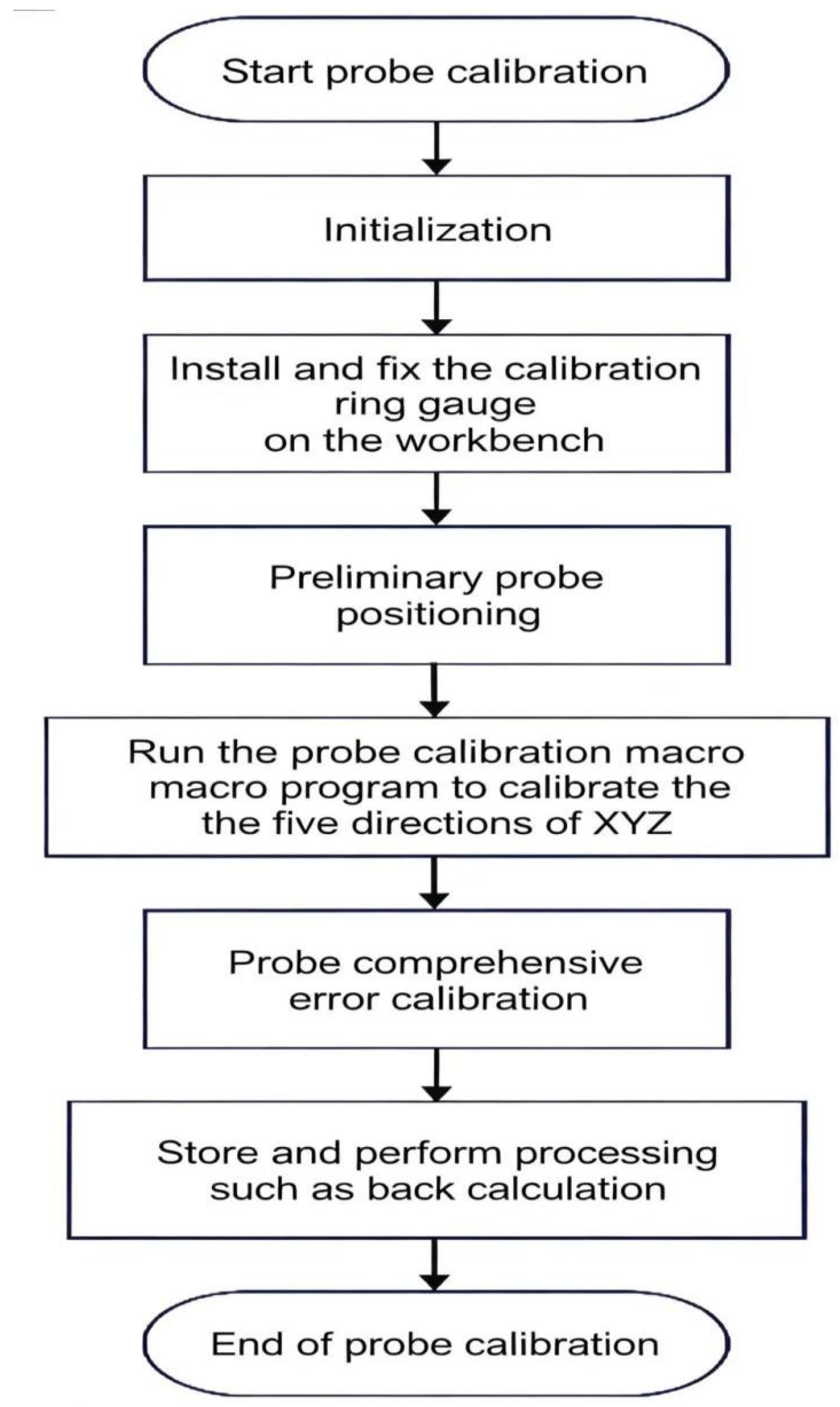
System calibration is an indispensable preprocessing procedure for guaranteeing the measurement accuracy of aircraft rudder surface flatness detection, as the calibration quality directly determines the sampling coordinate precision and subsequent plane fitting reliability. Multiple error sources, including spindle motion deviation, stylus deflection deformation, coordinate system mismatch and structural assembly clearance, will introduce systematic measurement errors during on-machine detection. Therefore, multi-dimensional calibration and targeted error compensation procedures are mandatory to satisfy the aviation flatness tolerance requirement of 0.1–0.3 mm for aircraft rudder surfaces. The implemented calibration system comprehensively covers four core modules: probe geometric parameter calibration, probe-machine coordinate matching calibration, trigger delay error calibration, and overall system precision verification. The complete standardized calibration workflow is visualized in Figure 10.

5.2.1. Probe Geometric Parameter Calibration

In this work, the trigger probe is calibrated through a standard block-based contact calibration approach. A high-precision ceramic standard block with a dimensional accuracy of 0.001 mm is securely mounted at the center of the machine tool worktable, ensuring that the parallelism between the block measuring surface and the worktable reference plane is limited within 0.002 mm. Driven by the CNC system, the probe contacts the standard measuring surface along the X, Y, and Z axes with diverse spatial postures. Twelve uniformly distributed contact points are sampled on each measuring surface, and the machine tool coordinate data corresponding to each trigger moment are synchronously recorded for subsequent calibration calculation.
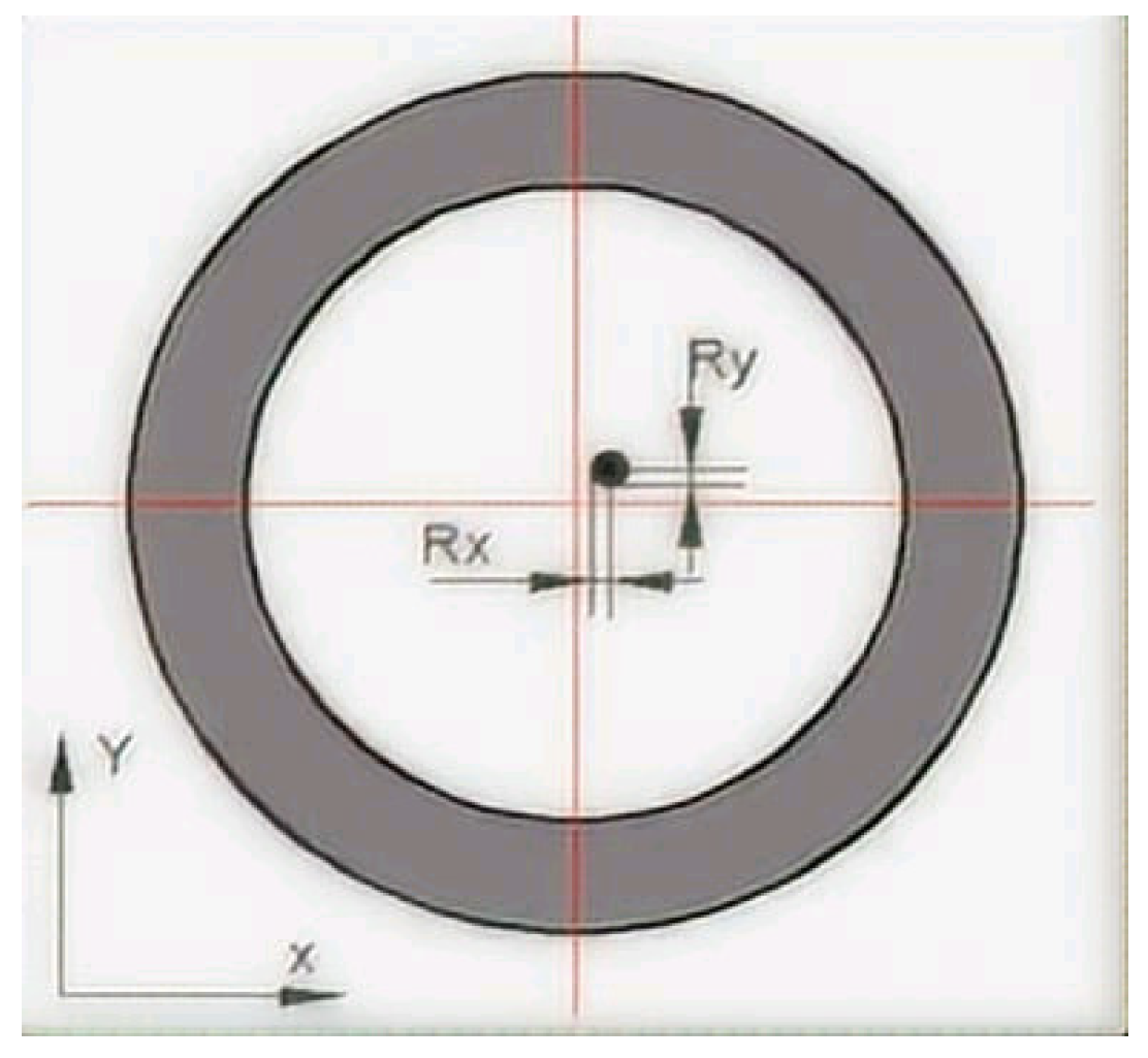
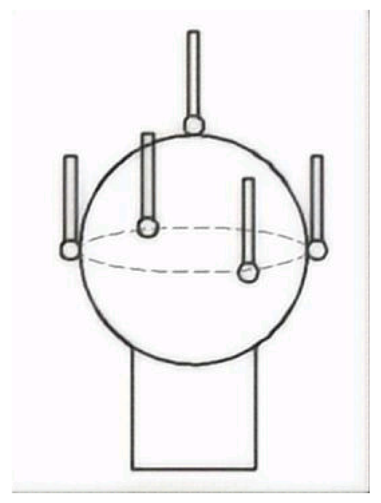
The core targets of probe geometric parameter calibration include the effective ball radius and stylus deflection error. Ring gauges and standard balls are adopted as the standard calibration artifacts in this procedure. The working principles of effective radius calibration using ring gauges and standard balls are demonstrated in Figure 11 and Figure 12, respectively.
Taking the probe ball center as the fitting benchmark, spherical surface fitting is conducted on all collected contact coordinate datasets. The deviation between the practically fitted radius and the theoretical standard radius is quantified as the radius compensation value. Meanwhile, coordinate deviations of sampling points under different probe postures are analyzed to fit the spatial deflection characteristic curve of the stylus, and the corresponding deflection compensation coefficients in the X, Y, and Z directions are determined. All calibrated compensation parameters are imported into the built-in probe parameter database of the CNC system to realize real-time compensation of probe geometric errors during on-machine detection. After comprehensive calibration, the system probe radius calibration error is controlled within 0.5 μm, and the overall stylus deflection error is restricted below 0.8 μm, which provides a high-precision hardware foundation for reliable flatness evaluation of aircraft rudder surfaces.

5.2.2. Probe and Machine Tool Coordinate System Association Calibration

The association calibration between the probe and machine tool coordinate systems aims to realize precise matching of their coordinate origins and compensate for coaxiality deviations induced during probe installation. This calibration procedure is implemented via a multi-directional triggering strategy based on a high-precision standard flat crystal, whose surface flatness error is constrained within 0.001 mm. The standard flat crystal is fixed on the machine tool worktable through vacuum adsorption. Initial coarse alignment is performed referring to the machine tool reference plane, followed by fine adjustment using a micrometer to ensure that the upper surface of the flat crystal is strictly perpendicular to the machine tool Z-axis, with the overall perpendicularity error controlled within 0.003 mm/m.
The probe is programmed to conduct grid sampling on the upper surface of the flat crystal to fully cover its effective measuring area. A total of 50 valid trigger points are uniformly collected, and the corresponding machine tool coordinate values (X, Y, Z) at each trigger moment are synchronously recorded, with detailed calibration results listed in Table 1. Taking the upper surface of the flat crystal as the reference benchmark, the least squares method is adopted to fit the calibration reference plane. The normal vector deviation between the fitted plane and the XY plane of the machine tool coordinate system, as well as the translational offset between the probe trigger origin and the machine tool coordinate origin, are quantitatively calculated to determine the axis-specific coordinate compensation values and coordinate system rotation correction angles for the X, Y, and Z directions.
All calibrated compensation parameters are imported into the coordinate association parameter library of the CNC system, achieving accurate coupling and matching between the probe and machine tool coordinate systems. After calibration, the comprehensive coordinate system association error is reduced to less than 1 μm, which effectively eliminates systematic coordinate deviation and guarantees the overall measurement accuracy of the on-machine detection system.

5.2.3. Calibration of Trigger Signal Hysteresis Error

The signal hysteresis error of the trigger probe originates from elastic stylus deformation during surface contact and the inherent response delay of the internal trigger mechanism. Such error induces inconsistent trigger coordinate deviations when the probe approaches the same contact point from different directions, presenting prominent nonlinear characteristics that necessitate targeted compensation via multi-directional approach calibration [37].
In this study, a standard flat crystal was adopted as the calibration reference, and a characteristic central point on the crystal surface was selected as the calibration target. The probe approached the target sequentially from X+, X−, Y+, Y−, and Z+ directions at three distinct feed speeds (5 mm/min, 10 mm/min, and 20 mm/min) to execute triggering sampling. Each direction and speed combination was repeated 10 times, and the real-time machine coordinates at all trigger moments were synchronously recorded.
Statistical analysis was performed on the acquired coordinate datasets to calculate the average trigger coordinates and directional deviations under different approach conditions. A spatial distribution model and feed-speed correction model for trigger hysteresis error were established through data fitting. On this basis, a hysteresis error compensation table was formulated and imported into the CNC system. The developed system enables real-time hysteresis error compensation for trigger coordinates according to the probe’s approach direction and feeding velocity. After calibration, the comprehensive signal hysteresis error is constrained within 0.6 μm, which thoroughly eliminates the adverse effects of approach direction and feed speed on triggering accuracy [38].

5.2.4. Overall System Accuracy Verification

After the completion of individual item calibration, overall systematic accuracy verification is mandatory to guarantee that the comprehensive measurement performance satisfies the flatness detection requirements for aircraft rudder surfaces. The verification procedure integrates standard block dimensional verification and standard planar flatness verification to comprehensively evaluate system measurement reliability.
(1) Standard block dimensional verification. Three groups of ceramic standard blocks with different specifications (10 mm, 20 mm, and 50 mm) were selected for dimensional measurement, with eight repeated tests conducted for each group. Statistical calculations of the average value and standard deviation demonstrate that the maximum dimensional measurement deviation is 0.9 μm, and the corresponding standard deviation is less than 0.3 μm, fully meeting the high-precision measurement requirements.
(2) Standard plane flatness verification. A standard planar specimen with a nominal flatness error of 0.002 mm was adopted for verification. The feature and curvature-adaptive point distribution strategy of the proposed detection system was applied for full-surface point cloud sampling. Flatness error evaluation was implemented via both the least squares method and the proposed bidirectionally coupled PSO–SA hybrid algorithm. By comparing the evaluated results with the nominal flatness value, the overall evaluation deviation is verified to be less than 1.2 μm, confirming the superior flatness detection accuracy of the calibrated system.

5.3. Analysis of Plane Degree Detection Experimental Results

5.3.1. Measured Object

A total of 24 aircraft control surface workpieces were selected as experimental samples, including 12 independent thin-walled skin components and 12 fully assembled control surface structures. The skin parts are aluminum alloy forming components, while the complete control surfaces are riveted assemblies consisting of outer skins and internal frameworks [39]. The detection region covers the core aerodynamic profile of each workpiece, with a uniform dimension of 800 mm × 600 mm. All test workpieces were sourced from the same aviation batch production line, covering typical manufacturing defects including skin forming warpage, frame assembly offset, and riveting-induced structural deformation. The sample set can fully reflect the actual surface error distribution characteristics of mass-produced aircraft control surfaces, ensuring the representativeness and validity of experimental verification.

5.3.2. Measurement Point Placement and Data Collection

Based on the geometric feature extraction from the control surface CAD model, a hybrid feature-based and curvature-adaptive point distribution strategy was adopted in this study. A total of 80 valid sampling points were uniformly deployed to cover the contour boundaries, stress-concentrated regions, deformation-prone areas, and geometric centers of the control surfaces, ensuring that the collected point cloud data can faithfully characterize the actual morphological features of complex curved surfaces. Relying on the fully calibrated trigger-based on-machine detection system, the probe moved along the pre-optimized inspection trajectory to complete three-dimensional coordinate acquisition of all sampling points. The obtained coordinate datasets were transmitted to the industrial computer via the CNC system for subsequent intelligent plane fitting and flatness error evaluation [40].

5.3.3. Comparative Experiment Design

Six representative algorithms were selected for comparative verification, including standard PSO, standard SA, CLPSO, adaptive cooling SA, traditional fixed-coupling PSO–SA, and the proposed bidirectionally coupled PSO–SA hybrid optimization algorithm. The identical sampling coordinate datasets of each control surface were independently processed by the six algorithms to solve the optimal fitting plane parameters and corresponding flatness errors. Three core evaluation indices were adopted: flatness error magnitude, fitting residual standard deviation, and single-workpiece detection efficiency. Each workpiece was repeatedly measured three times for each algorithm, and the arithmetic mean value was taken as the valid single-sample evaluation result to suppress random measurement errors.
To eliminate random contingency caused by limited sample size and quantitatively validate the statistical significance of performance differences among algorithms, one-way analysis of variance (ANOVA) combined with Tukey’s posthoc multiple comparison test was employed for statistical analysis on the flatness data of all 24 test samples. The significance level was set as α = 0.05. A pairwise p-value lower than 0.05 was defined as statistically significant accuracy difference between comparative algorithms. All statistical calculations were implemented via the MATLAB statistical toolbox to ensure objectivity and reproducibility of the quantitative comparison results.

5.4. Experimental Results and Analysis

Comparison of Core Indicators

The comprehensive experimental statistics of control surface flatness detection based on six algorithms are summarized in Table 2. In addition to the average flatness error, the table supplements the sample standard deviation, error variation range, and 95% confidence interval of flatness results, together with ANOVA pairwise significance comparison data, to quantitatively characterize the data dispersion degree and statistical differences among different algorithms. Specifically, flatness error and fitting residual standard deviation are adopted to evaluate detection accuracy, while single-workpiece detection time serves as the quantitative index for detection efficiency.
The results of one-way ANOVA reveal that the overall p-value corresponding to six groups of flatness error data is far below 0.05, which indicates statistically remarkable discrepancies in detection accuracy across all candidate algorithms. Subsequent Tukey pairwise multiple comparisons further demonstrate that the flatness error solved by the proposed bidirectionally coupled PSO–SA algorithm is significantly lower than that yielded by the other five benchmark algorithms.
It should be clarified that the total detection cycle recorded in experiments corresponds to the complete on-machine measurement workflow, ranging from measurement program startup to the final output of flatness error results, rather than merely the pure plane fitting computation time for 80 sampling points. The full workflow covers collision-free measurement trajectory planning under multi-dimensional constraints, trigger-probe coordinate acquisition, coordinate error compensation preprocessing, and iterative solving of the minimum zone fitting plane. The minute-scale time gaps between different algorithms primarily stem from differences in trajectory optimization efficiency and hardware servo motion duration of the probe, instead of minor gaps in plane fitting computational overhead.
The proposed bidirectionally coupled PSO–SA realizes collaborative integrated optimization of trajectory planning and plane fitting via closed-loop bidirectional information interaction. The residual-adaptive nonlinear inertia weight strategy accelerates global optimal trajectory searching for sampling points, while the measurement noise-modified Metropolis criterion avoids redundant idle strokes and frequent safety plane switching of the probe. By contrast, standard PSO easily suffers premature convergence toward suboptimal measurement trajectories; standalone SA lacks parallel population searching capacity, leading to extremely slow trajectory iteration, redundant probe travel distance and prolonged hardware sampling duration. Moreover, the bidirectional feedback iteration mechanism of the proposed algorithm cuts repetitive residual calculation during plane fitting, further reducing auxiliary computation time for data preprocessing and error compensation. All the above merits collectively contribute to a prominent reduction in the overall inspection cycle.
As summarized from multi-sample statistical data in Table 2, the average flatness error solved by the proposed bidirectionally coupled PSO–SA hybrid algorithm reaches 29.7 μm, which is substantially lower than standard PSO (42.5 μm), standard SA (48.3 μm), CLPSO (37.1 μm), adaptive cooling SA (34.6 μm), and conventional fixed-coupling PSO–SA (32.4 μm). Quantitatively, the flatness error of the proposed method is reduced by 30.1% relative to standard PSO and 38.5% relative to standard SA, presenting evident precision improvement. The sample standard deviation of the proposed algorithm is merely 1.3 μm, the minimum value among all six algorithms, which verifies superior stability and repeatability of detection results. Its fitting residual standard deviation is only 7.8 μm, markedly outperforming all comparative algorithms and proving that the fitted reference plane matches the actual aerodynamic profile of control surfaces more closely. All measured flatness errors are far below 0.1 mm, fully complying with the aviation flatness tolerance specification of 0.1–0.3 mm for aircraft control surfaces.
In terms of detection efficiency, the average single-workpiece inspection time of the bidirectionally coupled PSO–SA algorithm is only 2.1 min, shorter than all five benchmark algorithms. Compared with standard PSO, the total inspection time is decreased by 34.4%, and a 63.2% time reduction is achieved relative to standard SA. The proposed method enables minute-level online inspection that satisfies the tact requirements of mass aircraft production lines.
Statistical significance analysis further confirms that the overall ANOVA p-value of six sample groups is less than 0.05, and all p-values from pairwise Tukey comparisons between the proposed algorithm and the other five benchmarks are below 0.05. This evidence proves that the superior fitting precision of the bidirectionally coupled PSO–SA framework does not originate from random sample fluctuation; instead, it possesses statistically significant accuracy advantages over all mainstream comparative algorithms.

5.5. Experimental Conclusion

Online measurement experiments carried out on 12 aircraft control surface skin components and 12 fully assembled control surfaces verify that the flatness online detection scheme based on the bidirectionally coupled PSO–SA hybrid optimization algorithm features high measurement accuracy, outstanding detection efficiency and robust result stability. Sufficient batch samples together with statistical significance analysis eliminate random interference caused by small-scale tests. One-way ANOVA combined with Tukey multiple comparison quantitatively confirms that the proposed algorithm achieves statistically significant optimization gains in flatness evaluation accuracy when compared with standard PSO, standard SA, CLPSO, adaptive cooling SA and conventional fixed-coupling PSO–SA. The solved flatness error satisfies the 0.1–0.3 mm tolerance standard for aircraft control surfaces, and the single-workpiece inspection cycle conforms to the minute-level tact demand of production lines. The fitting results exhibit excellent consistency and robustness, which successfully realizes intelligent online flatness detection for aircraft control surfaces and validates the engineering feasibility and practicability of the proposed method under real industrial working conditions.

6. Conclusions

(1) Aiming at the prominent drawbacks of existing flatness online detection for aircraft control surfaces, including low plane fitting efficiency, high susceptibility to local optima and insufficient automation, this study proposes a novel detection framework built upon the bidirectionally coupled PSO–SA hybrid optimization algorithm. Combined with CNC trigger-based on-machine measurement technology, an integrated detection system covering point cloud data acquisition, intelligent plane fitting and flatness error evaluation is constructed. The effectiveness and practical feasibility of the proposed method are comprehensively validated via numerical simulations and physical engineering experiments.
(2) Distinct from generic serial PSO–SA architectures, modified PSO, modified SA, GA, ACO, linear programming and traditional minimum zone fitting approaches, this work establishes a dedicated bidirectionally coupled PSO–SA optimization theory tailored specifically for rudder surface flatness evaluation, rather than simply transplanting existing metaheuristic algorithms for engineering applications. Two customized core modules, namely the residual-adaptive nonlinear inertia weight strategy and measurement noise-modified Metropolis acceptance criterion, form a progressive coarse-to-fine two-stage optimization logic for solving the non-convex minimum enclosing zone fitting problem of curved aircraft rudder surfaces. The proposed framework fundamentally addresses three critical defects of benchmark algorithms: premature convergence of improved PSO variants, low global searching efficiency of standalone SA, and insufficient anti-noise robustness of linear programming and conventional minimum zone methods under trigger sampling noise. In terms of convergence speed, plane fitting precision, anti-noise robustness and local optimum escape capability, the customized bidirectionally coupled PSO–SA method achieves overwhelming performance superiority over all comparative algorithms.
(3) MATLAB-based comparative simulation results indicate that the proposed hybrid algorithm requires 22% fewer iterations to reach stable convergence accuracy than standard PSO and 41% fewer iterations than standard SA. On average, its plane fitting error is 11 μm lower than standard PSO and 15 μm lower than standard SA; meanwhile, the standard deviation of fitting results is reduced by 32% compared with standard PSO and 38% compared with standard SA, generating fitted planes with higher consistency against the theoretical ideal reference plane. The comprehensive optimization performance of the proposed algorithm is substantially improved.
(4) After multi-dimensional calibration of the CNC trigger-based on-machine detection system, all systematic measurement errors are controlled within 1 μm, guaranteeing excellent overall measurement precision. Physical measurement experiments on aircraft rudder skin components show that the flatness error solved by the proposed algorithm reaches 29.7 μm, which falls within the 0.1–0.3 mm aviation tolerance band. The single-workpiece full inspection cycle only takes 2.1 min, corresponding to a 34.4% time reduction relative to standard PSO and a 63.2% reduction relative to standard SA. The proposed scheme realizes high-precision and high-efficiency on-machine flatness inspection for aeronautical curved components.
(5) This work integrates intelligent metaheuristic optimization algorithms with CNC on-machine trigger measurement technology, delivering an innovative technical solution for intelligent online flatness detection of irregular aircraft structural components. It also provides valuable theoretical support and engineering references for form and position error evaluation of other complex irregular industrial workpieces under noisy measurement environments.

Author Contributions

Z.Y.: Conceptualization, Methodology, Software, Investigation, Formal analysis, Visualization, Writing—original draft; J.G.: Investigation, Data curation, Validation; W.H.: Investigation, Data curation; Y.Y.: Validation, Formal analysis; Y.C.: Conceptualization, Supervision, Y.Z.: Resources, X.Z.: Resources, Validation. All authors have read and agreed to the published version of the manuscript.

Funding

This work was supported by the General Program of Hebei Provincial Natural Science Foundation under Grant No. E202502164 (project duration: January 2025December 2027).

Data Availability Statement

The datasets generated and analyzed in this study are not publicly available. The data involves self-developed test system parameters, proprietary equipment calibration information and subsequent research content, and is restricted by project confidentiality and intellectual property protection. Relevant data can be obtained from the corresponding author upon reasonable request.

Conflicts of Interest

The author declares no conflicts of interest.

References

  1. Lu, R. Metrological error control for aero-engine gear tooth surface considering flatness. Comput. Meas. Control 2026, 1–9. Available online: https://link.cnki.net/urlid/11.4762.TP.20260414.1809.004 (accessed on 25 June 2026).
  2. Sheng, D.L.; Hao, J.; Ma, F.Y.; Zhan, J. Evaluation of flatness error based on fast searching ideal reference plane. J. China Univ. Metrol. 2025, 36, 521–526+605. [Google Scholar]
  3. Wang, F.Y.; Li, W.L.; Chen, F.; He, Q. Experimental study on extraction of performance degradation indicators for electric vehicle motors. Electron. Des. Eng. 2025, 33, 69–74. [Google Scholar] [CrossRef]
  4. He, J.F.; Jiang, X.Y. Motor degradation assessment method based on GMM and information entropy regularization. China Plant Eng. 2025, 119–122. [Google Scholar]
  5. Ge, L. Research on Health State Assessment and Maintenance Strategy of Wind Turbine Units Based on Data Drive. Ph.D. Thesis, Xi’an University of Technology, Xi’an, China, 2025. [Google Scholar] [CrossRef]
  6. Li, X.L. Study on Performance Degradation Stage Division and Remaining Useful Life Prediction of Motor Bearings. Ph.D. Thesis, Nanjing University of Information Science and Technology, Nanjing, China, 2025. [Google Scholar] [CrossRef]
  7. Xiao, S.H. Intelligent Detection Equipment for Flatness of Super-Large Diameter Wind Turbine Tower Flanges; Hunan Hengyue Heavy Steel Structure Engineering Co., Ltd.: Hengyang, China, 2025. [Google Scholar]
  8. Chen, X.Y. Comparison of optical flatness measurement methods and consistency test of measurement results. Metrol. Meas. Tech. 2025, 51, 94–96+100. [Google Scholar] [CrossRef]
  9. Yang, L.; Zhang, Y.J.; Tie, Z.; Wan, L. Structural design of high-precision calibration device for prism working surface flatness based on laser interferometer. China Insp. Test. 2025, 33, 13–17. [Google Scholar] [CrossRef]
  10. Wang, J.; Chen, Q.; Zhang, Z.; Zhao, Y.; Zhang, L. Design of accelerated life test device for servo motor bearings considering shaft current damage. Chin. J. Eng. Des. 2025, 32, 562–568. [Google Scholar]
  11. Sun, C.F.; Sui, K.L.; Chang, H.; He, Y.B.; Wang, Y. Research on large flange flatness measurement method based on rotary line structured light and machine vision. Manuf. Autom. 2024, 46, 83–90. [Google Scholar]
  12. Shi, X.F. Research on Fault Diagnosis and Performance Degradation Evaluation Method of Motor Rolling Bearings Based on Vibration Signal Analysis. Ph.D. Thesis, Zhejiang University, Hangzhou, China, 2023. [Google Scholar] [CrossRef]
  13. Luan, J.-Y.; Xu, L.-L.; Wu, C.-Y.; Jing, Y. Motor life evaluation based on degradation of performance parameters. Mech. Electr. Eng. Technol. 2022, 51, 272–275. [Google Scholar]
  14. Yin, B. Research on Evaluation of Servo Motor Bearing Performance Degradation and Life Prediction. Ph.D. Thesis, Hunan University, Changsha, China, 2022. [Google Scholar]
  15. Wang, H.R. Performance Degradation Evaluation and Life Prediction of Robot Servo Motor Bearings. Ph.D. Thesis, Hunan University, Changsha, China, 2020. [Google Scholar] [CrossRef]
  16. Liu, Y.M. Research on Performance Degradation Evaluation and Prediction of Servo Motors Based on CHMM. Ph.D. Thesis, Kunming University of Science and Technology, Kunming, China, 2019. [Google Scholar] [CrossRef]
  17. Wu, F.B. Research on Remaining Useful Life Prediction Method of Permanent Magnet Synchronous Motors. Ph.D. Thesis, Zhejiang Sci-Tech University, Hangzhou, China, 2018. [Google Scholar]
  18. Wang, L.; Yu, C.C.; Shi, Y.; Zhang, H. Extraction of motor performance degradation features based on vibration signal analysis. Comput. Simul. 2014, 31, 416–421. [Google Scholar]
  19. Yang, Y. Reliability analysis method of spaceborne scanning components based on performance degradation. Sci. Technol. Eng. 2011, 11, 8256–8261. [Google Scholar]
  20. Zewail, I.; Shokair, M.; Ghallab, R.; Zayed, M.M. Interference-aware power allocation in GFDM- and OFDM-based cognitive radio networks using hybrid PSO-SA optimization. Wirel. Pers. Commun. 2026, 146, 3859–3901. [Google Scholar] [CrossRef]
  21. Sun, Y.; Yan, P.; Li, Y.; Miao, H.; Zheng, H.; Guo, J. Multi-weapon Cooperative Interception Planning and Timing Optimization Method Based on Improved SA-ACO Algorithm. J. Proj. Rockets Missiles Guid. 2026, 46, 269–280. [Google Scholar] [CrossRef]
  22. Talib, A.M.; Alsaid, B.; Turky, A.; Nasir, Q.; Mokhamed, T. PSO-SA: Neural architecture search optimization via simulated annealing and particle swarm for image classification applications. Neural Comput. Appl. 2026, 38, 114. [Google Scholar] [CrossRef]
  23. Hou, S.S.; Hu, X.D.; Dai, N.; Yu, B.; Fang, L.; Shen, C.; Ma, H. Research on time delay optimization of spinning data collection based on PSO-SA algorithm. Softw. Eng. 2025, 28, 50–55. [Google Scholar] [CrossRef]
  24. Fu, H.; He, J.; Wang, Y.; Ai, S.; Feng, Z. Research on Digital Twin Model of Gearbox Based on Improved PSO Algorithm. Eng. Sci. Technol. 2026, 1–21. Available online: https://link.cnki.net/urlid/51.1773.tb.20260617.1656.004 (accessed on 25 June 2026).
  25. Wu, H.; Liu, F.; Xia, G.; Dai, Y. Research on Tunnel Equipment Trajectory Tracking Using an Improved PSO Pure Tracking Model. Mech. Sci. Technol. 2026, 1–5. [Google Scholar] [CrossRef]
  26. Ni, J.Y.; Shang, H.Z.; Zhang, F.J.; Gu, H.Q. Adaptive PSO path planning algorithm fused with improved simulated annealing. J. Tianjin Univ. Technol. 2024, 1–7. Available online: https://link.cnki.net/urlid/12.1374.n.20241030.0846.008 (accessed on 25 June 2026). [CrossRef]
  27. Zhang, H.; Liu, J.; Zhou, J.; Liu, P. Research on Design and Optimization of a Return-Force Linkage Actuator Based on Particle Swarm Algorithm. Hydraul. Pneum. Seal. 2025, 45, 115–121. [Google Scholar]
  28. Liu, L.; Zhang, S.; Ran, S.; Shen, L. Research on source term inversion method based on PSO-SA algorithm. Mod. Electron. Tech. 2024, 47, 100–104. [Google Scholar] [CrossRef]
  29. Su, M.J.; Xiao, B.D.; Yue, L.L. Energy-saving optimization of urban rail transit ATO based on improved PSO-SA algorithm. Sens. Microsyst. 2023, 42, 64–67+76. [Google Scholar] [CrossRef]
  30. Shi, W.L.; Ang, L.; Wang, J.G.; Kong, X. An intelligence-based hybrid PSO-SA for mobile robot path planning in warehouse. J. Comput. Sci. 2023, 67, 101938. [Google Scholar] [CrossRef]
  31. Kou, Y.J. Research on Workflow Scheduling Based on Improved Particle Swarm Optimization Algorithm. Ph.D. Thesis, Nanjing University of Posts and Telecommunications, Nanjing, China, 2022. [Google Scholar] [CrossRef]
  32. Li, L.C.; Du, W.; Chen, Y.; Chen, H.; Wei, J. Research on operation optimization of central air conditioning cold source system based on PSO-SA algorithm. J. Phys. Conf. Ser. 2021, 2087, 012098. [Google Scholar] [CrossRef]
  33. Bilandi, N.; Verma, K.H.; Dhir, R. hPSO-SA: Hybrid particle swarm optimization-simulated annealing algorithm for relay node selection in wireless body area networks. Appl. Intell. 2020, 51, 1410–1438. [Google Scholar] [CrossRef]
  34. Tang, H.; Chen, R.; Li, Y.; Peng, Z.; Guo, S.; Du, Y. Flexible job-shop scheduling with tolerated time interval and limited starting time interval based on hybrid discrete PSO-SA: An application from a casting workshop. Appl. Soft Comput. 2019, 78, 176–194. [Google Scholar] [CrossRef]
  35. Qi, Y.; Li, C.; Jiang, P.; Jia, C.; Liu, Y.; Zhang, Q. Research on demodulation of FBG sensor network based on PSO-SA algorithm. Optik 2018, 164, 647–653. [Google Scholar] [CrossRef]
  36. Qiao, H.; Deng, S.; Zhi, H.; Zhou, Y.; Xiao, T. Research on the Design of Inter-stage Separation Scheme for TSTO Based on Numerical Virtual Flight. Acta Aeronaut. Astronaut. Sin. 2026, 1–21. Available online: https://link.cnki.net/urlid/11.1929.V.20260508.1547.007 (accessed on 25 June 2026).
  37. Zhou, D.P.; Zhen, C.; Qu, X.L. Research on active-passive composite fault-tolerant control for carrier landing aircraft considering control surface efficiency loss. Acta Aeronaut. Astronaut. Sin. 2026, 47, 246–265. Available online: https://link.cnki.net/urlid/11.1929.v.20260304.1616.008 (accessed on 25 June 2026).
  38. Qin, Q.; Cao, J.; Zhang, W. Development and Application of a Test System for Starting Torque of Gas Steering Control Mechanism. Mech. Des. Manuf. 2026, 1–5. [Google Scholar] [CrossRef]
  39. Xiang, S.; Dai, Y. Study on the Mechanism of Angle of Attack Effects on Nonlinear Flutter of Gap Control Surfaces. J. Beihang Univ. 2026, 1–23. [Google Scholar] [CrossRef]
  40. Zhao, Y.P.; Wu, Y.F.; Hou, P.; Guo, P. Design of automatic test system for fixed-wing UAV control surface. Autom. Instrum. 2025, 40, 58–61+67. [Google Scholar] [CrossRef]
Figure 1. Schematic diagram of measurement path planning, process simulation and collision avoidance. The Chinese text in the software interface represents the function menu of CNC on-machine detection.
Aerospace 13 00671 g001
Figure 2. Working Principle Diagram of the On-machine Measurement System for CNC Machine Tool.
Aerospace 13 00671 g002
Figure 3. 3D visualization of measurement path planning, process simulation and collision avoidance for shaft part on-machine detection.
Aerospace 13 00671 g003
Figure 4. Flowchart of the process for solving the parameters of the ideal plane equation based on the PSO-SA hybrid optimization algorithm.
Aerospace 13 00671 g004
Figure 5. Comparison of convergence curves of the objective function for flatness minimum zone optimization with different algorithms.
Aerospace 13 00671 g005
Figure 6. Comparison of flatness errors solved by different algorithms under various quantities of measuring points.
Aerospace 13 00671 g006
Figure 7. 3D visualization comparison of rudder reference planes fitted by different optimization algorithms.
Aerospace 13 00671 g007
Figure 8. Hardware structure schematic of CNC on-machine inspection system.
Aerospace 13 00671 g008
Figure 9. Physical installation diagram of trigger probe on CNC machine tool.
Aerospace 13 00671 g009
Figure 10. Flowchart of trigger probe calibration procedure.
Aerospace 13 00671 g010
Figure 11. Effective radius for ring gauge calibration.
Aerospace 13 00671 g011
Figure 12. Effective radius for standard sphere calibration.
Aerospace 13 00671 g012
Table 1. Calibration Results of the Triggering Probe Online Detection System.
Parameter MeaningCalibration ValueParameter MeaningCalibration Value
X-axis translation compensation0 mmX-axis rotation angle (around X)
Y-axis translation compensation0 mmY-axis rotation angle (around X)
X-axis probe length compensation (+)2.014 mmZ-axis rotation angle (around Z)
Y-axis probe length compensation (+)−2.014 mmX-axis perpendicularity compensation0 mm
Y-axis probe length compensation (+)2.823 mmY-axis perpendicularity compensation0 mm
Z-axis probe length compensation (−)0.03 mmZ-axis perpendicularity compensation0 mm
Table 2. Comparison of Plane Degree Detection Experimental Results of the Three Algorithms. (a) Statistical indicators of flatness detection accuracy; (b) Inspection time consumption statistics.
(a)
AlgorithmAverage Flatness Error (μm)Sample Standard Deviation (μm)Error Range (μm)95% Confidence Interval (μm)Flatness Error Reduction vs. Standard PSOFlatness Error Reduction vs. Standard SAFitting Residual Standard Deviation
Standard PSO42.52.139.6~45.8[41.2, 43.8]12.6
Standard SA48.32.745.1~51.9[46.7, 49.9]15.8
CLPSO37.11.935.0~39.4[36.0, 38.2]12.7%23.2%10.3
Adaptive Cooling SA34.61.732.4~36.7[33.6, 35.6]18.6%28.4%9.5
Fixed Coupling PSO-SA32.41.530.6~34.2[31.5, 33.3]23.8%32.9%8.6
Proposed PSO-SA29.71.327.9~30.5[28.9, 30.5]30.1%38.5%7.8
(b)
AlgorithmInspection Time (min)Time Reduction vs. PSOTime Reduction vs. SA
Standard PSO3.2
Standard SA5.7
CLPSO2.812.5%50.9%
Adaptive Cooling SA3.5−9.4%38.6%
Fixed Coupling PSO-SA2.521.9%56.1%
Proposed PSO-SA2.134.4%63.2%
Disclaimer/Publisher’s Note: The statements, opinions and data contained in all publications are solely those of the individual author(s) and contributor(s) and not of MDPI and/or the editor(s). MDPI and/or the editor(s) disclaim responsibility for any injury to people or property resulting from any ideas, methods, instructions or products referred to in the content.